US4912643A - Position sensing apparatus - Google Patents
Position sensing apparatusDownload PDFInfo
- Publication number
- US4912643A US4912643AUS07/115,757US11575787AUS4912643AUS 4912643 AUS4912643 AUS 4912643AUS 11575787 AUS11575787 AUS 11575787AUS 4912643 AUS4912643 AUS 4912643A
- Authority
- US
- United States
- Prior art keywords
- radiation
- sensor
- datum
- movable sensor
- movable
- Prior art date
- Legal status (The legal status is an assumption and is not a legal conclusion. Google has not performed a legal analysis and makes no representation as to the accuracy of the status listed.)
- Expired - Fee Related
Links
Images


Classifications
- G—PHYSICS
- G05—CONTROLLING; REGULATING
- G05D—SYSTEMS FOR CONTROLLING OR REGULATING NON-ELECTRIC VARIABLES
- G05D1/00—Control of position, course, altitude or attitude of land, water, air or space vehicles, e.g. using automatic pilots
- G05D1/02—Control of position or course in two dimensions
- G05D1/021—Control of position or course in two dimensions specially adapted to land vehicles
- G05D1/0231—Control of position or course in two dimensions specially adapted to land vehicles using optical position detecting means
- G05D1/0238—Control of position or course in two dimensions specially adapted to land vehicles using optical position detecting means using obstacle or wall sensors
- G05D1/024—Control of position or course in two dimensions specially adapted to land vehicles using optical position detecting means using obstacle or wall sensors in combination with a laser
- G—PHYSICS
- G01—MEASURING; TESTING
- G01C—MEASURING DISTANCES, LEVELS OR BEARINGS; SURVEYING; NAVIGATION; GYROSCOPIC INSTRUMENTS; PHOTOGRAMMETRY OR VIDEOGRAMMETRY
- G01C15/00—Surveying instruments or accessories not provided for in groups G01C1/00 - G01C13/00
- G01C15/002—Active optical surveying means
- G—PHYSICS
- G01—MEASURING; TESTING
- G01S—RADIO DIRECTION-FINDING; RADIO NAVIGATION; DETERMINING DISTANCE OR VELOCITY BY USE OF RADIO WAVES; LOCATING OR PRESENCE-DETECTING BY USE OF THE REFLECTION OR RERADIATION OF RADIO WAVES; ANALOGOUS ARRANGEMENTS USING OTHER WAVES
- G01S3/00—Direction-finders for determining the direction from which infrasonic, sonic, ultrasonic, or electromagnetic waves, or particle emission, not having a directional significance, are being received
- G01S3/78—Direction-finders for determining the direction from which infrasonic, sonic, ultrasonic, or electromagnetic waves, or particle emission, not having a directional significance, are being received using electromagnetic waves other than radio waves
- G01S3/782—Systems for determining direction or deviation from predetermined direction
- G01S3/783—Systems for determining direction or deviation from predetermined direction using amplitude comparison of signals derived from static detectors or detector systems
- G01S3/784—Systems for determining direction or deviation from predetermined direction using amplitude comparison of signals derived from static detectors or detector systems using a mosaic of detectors
- G—PHYSICS
- G01—MEASURING; TESTING
- G01S—RADIO DIRECTION-FINDING; RADIO NAVIGATION; DETERMINING DISTANCE OR VELOCITY BY USE OF RADIO WAVES; LOCATING OR PRESENCE-DETECTING BY USE OF THE REFLECTION OR RERADIATION OF RADIO WAVES; ANALOGOUS ARRANGEMENTS USING OTHER WAVES
- G01S5/00—Position-fixing by co-ordinating two or more direction or position line determinations; Position-fixing by co-ordinating two or more distance determinations
- G01S5/16—Position-fixing by co-ordinating two or more direction or position line determinations; Position-fixing by co-ordinating two or more distance determinations using electromagnetic waves other than radio waves
- G01S5/163—Determination of attitude
- G—PHYSICS
- G05—CONTROLLING; REGULATING
- G05D—SYSTEMS FOR CONTROLLING OR REGULATING NON-ELECTRIC VARIABLES
- G05D1/00—Control of position, course, altitude or attitude of land, water, air or space vehicles, e.g. using automatic pilots
- G05D1/02—Control of position or course in two dimensions
- G05D1/021—Control of position or course in two dimensions specially adapted to land vehicles
- G05D1/0255—Control of position or course in two dimensions specially adapted to land vehicles using acoustic signals, e.g. ultra-sonic singals
- G—PHYSICS
- G05—CONTROLLING; REGULATING
- G05D—SYSTEMS FOR CONTROLLING OR REGULATING NON-ELECTRIC VARIABLES
- G05D1/00—Control of position, course, altitude or attitude of land, water, air or space vehicles, e.g. using automatic pilots
- G05D1/02—Control of position or course in two dimensions
- G05D1/021—Control of position or course in two dimensions specially adapted to land vehicles
- G05D1/0276—Control of position or course in two dimensions specially adapted to land vehicles using signals provided by a source external to the vehicle
- G05D1/028—Control of position or course in two dimensions specially adapted to land vehicles using signals provided by a source external to the vehicle using a RF signal
Definitions
- the present inventionrelates to a method and apparatus for sensing position particularly for use in land surveying and earth moving machinery control.
- U.K. patent application No. 2,089,615(Tsumura) describes the use of one or more scanning laser beams in either a horizontal or a vertical plane for defining a path, which a vehicle fitted with a movable sensor is to follow. Position is determined solely with respect to the location on the movable sensor, at which the scanning beam is detected. Vertical position relative to a scanning beam in a horizontal plane may be determined, however, as the range of movement which can be detected is limited to the physical dimensions of the movable sensor, measurement of movement in a horizontal plane may not be measured outside of a pre-determined track, he width of which is determined by these physical dimensions.
- the present inventionis directed towards providing an improved construction of position sensing apparatus and additionally providing means for controlling earth moving machinery.
- the inventionis further directed towards providing an improved method of sensing position.
- a position sensing apparatuscomprising:
- a base stationcomprising a radiation generator for generating a rotating beam of radiation
- datum meansassociated with the base station to provide a time datum for comparison with the time at which the movable sensor detects the beam
- said datum meanscomprising a datum sensor for detecting the beam from the radiation generator
- said means for measuring the positional anglecomprises timing means for determining the time delay between the receiving of the radiation beam by the datum sensor and the movable sensor.
- the position sensing apparatuscomprises two base stations, each base station comprising a radiation generator, the generators being spaced-apart a known distance along the datum line and each radiation generator having an associated datum sensor.
- the datum sensorsare located on the datum line.
- each radiation generatorgenerates a rotating beam of radiation, the beams rotating in a common plane, each at a constant angular velocity and the rotating beams are differentiated.
- the beamsare differentiated by rotating tee beams in opposite directions in a common plane.
- the radiation beamis a laser beam.
- the or each datum sensorincludes a radio transmitter for transmitting a radio signal immediately on detection of a radiation beam from the associated radiation generator
- the movable sensorincludes a radio receiver for receiving radio signals transmitted by the datum sensor
- the movable sensorincludes differentiating means for determining from which radiation generator a radiation beam is emitted and from which datum sensor a radio signal is transmitted, and timing means for determining the time delay between detection of a radiation beam from each radiation generator and reception of a radio signal from the associated datum sensor
- the movable sensorfurther comprising processing means for determining the positional angle defined between position lines between the movable sensor and each radiation generator and the datum line in response to time delay inputs and an input of the distance between the two radiation generators.
- the radio transmitter of the or each datum sensoris a two-channel radio frequency tone transmitter for operation at the upper level of the VHF band.
- the apparatusincludes means for determining the level of the movable sensor.
- the levelis preferably determined with reference to the datum line.
- the movable sensorcomprises a plurality of vertically spaced-apart radiation detectors, the distance between the radiation detectors and the height of the movable sensor above the ground determining the level of the sensor above the datum line.
- the position sensing apparatusis for use with earth moving machinery.
- the position sensing apparatusincludes control means which utilises the control and difference data to control an earth moving machine.
- the position sensing apparatusincludes means for transmitting determined position and level values to a separate memory means.
- the position sensing apparatuscomprises a display means for outputting determined position and level data.
- the inventionprovides a method of determining the position of a movable sensor relative to a datum comprising the steps of:
- the methodcomprises the additional steps of:
- the datum sensordispenses with the need for a reference rotating laser beam and thus only one rotating beam is required at each base station. This greatly simplifies the construction of the apparatus. As the angle between the two position lines and the datum line may be calculated at each radiation generator, it will be appreciated that the position of the movable sensor in a given plane may be continually and accurately measured.
- radio transmitters and receiversfor enabling the time at which a laser beam is detected by a datum sensor to be stored for comparison allows this to be done accurately and at relatively small expense.
- radio signalsmay be differentiated at the movable sensor using known techniques.
- the detection and processing circuitrymay be contained in the movable sensor, which in effect, acts as the "centre" of the position sensing apparatus. This is a significant advantage as the required positiOn infOrmation can then be transmitted for display i a vehicle on which the movable sensor is mounted. This is very useful for control purposes.
- One of the problems with major land excavation and infillis the difficulty in controlling predetermined depths and gradients on the site, whether the site has to be prepared by graders, excavators or any form of earth moving machinery.
- the operator of the earth moving machineryshould be given accurate information as to the height over or under datum required at any particular location on the site. Indeed, by doing this, the invention might in many cases obviate the need for a driver by the use of relatively simple control equipment for the earth moving machinery. In any case, such information would greatly reduce the complexity of the task he or she is required to do.
- the inventionallows paths followed by a vehicle having a movable sensor to be stored for analysis. This is particularly useful for land surveying.
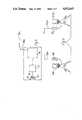
- FIG. 1is a diagrammatic plan view of the lay-out of a position sensing apparatus according to the invention
- FIG. 2is a diagram illustrating the lay-out for calculation purposes
- FIG. 3is a diagrammatic perspective views of the apparatus in use with earth moving machinery
- FIG. 4is a side view of portion of the apparatus
- FIG. 5is a block diagram illustrating the operation of a portion of the apparatus
- FIG. 6is a diagrammatic view of a movable radiation sensor according to the invention.
- FIG. 7is a detailed side view of the movable radiation sensor of FIG. 6;
- FIG. 8is a flow diagram illustrating one mode of operation of the apparatus.
- FIG. 9is a flow diagram illustrating another operation of the apparatus.
- FIG. 10is a circuit diagram of a portion of the movable radiation sensor of FIG. 6.
- the present inventionprovides an apparatus and method for determining the position and level of movable objects such as earth moving machines. To help in understanding the invention the overall lay-out of the position sensing apparatus and its method of operation will be discussed initially with reference to FIGS. 1 to 3.
- FIGS. 1 to 3there is illustrated a method of determining the position of a movable sensor 6 forming part of a position sensing apparatus, indicated generally by the reference numeral 1.
- Two base stationscomprising laser generators 2a and 2b each for generating a rotating laser beam are positioned on a datum line L and are spaced-apart a known distance a.
- Datum radiation sensors 7a and 7bare provided for each generator 2a, 2b and positioned on the datum line L, the datum sensor 7a being associated with the laser generator 2a and the datum sensor 7b being associated with the laser generator 2b. To differentiate the beams the direction of rotation of the laser beams from the laser generators 2a and 2b are opposite, the beam generated by the generator 2a being clockwise and the beam generated by the beam 2b being anti-clockwise.
- the movable radiation sensor 6may be secured to a moving object, such as an earth moving machine, the position of which relative to the datum is to be determined.
- the level of the ground at the movable sensor 6will be obtained by knowing at what vertical position on the movable sensor 6, the laser beams are detected. For example, referring to FIG. 6, if H is the height of the movable sensor 6 above ground and x is the vertical separation of separate radiation detectors on the movable sensor 6, the level Z of the datum line L with respect to the ground at the movable sensor 6 may be determined by the following formula: ##EQU4## where the laser beam is detected at its' lowermost edge by the Nth separate radiation detector and the beam has a width of Mx.
- FIGS. 3 to 7the position sensing apparatus is illustrated in more detail.
- the apparatusis illustrated in use with a bulldozer 3 and a grader 4, each of which carries a movable radiation sensor 6.
- Each of the movable radiation sensors 6comprises a staff with separate optical sensors.
- a two channel radio frequency tone receiveris provided for each sensor 6 to receive signals transmitted by radio frequency tone transmitters associated with each datum sensor 7a, 7b.
- the receiveris connected to a micro-computer located in the earth moving machinery.
- each datum radiation sensor 7is mounted on the tripod of its associated laser generator 2(a) or 2(b) so that the datum sensors are on the datum line L, which is preferably horizontal.
- the radio frequency tone transmitters of the datum radiation sensors 7(a) and 7(b)each have a vertical antenna 19(a) and 19(b) respectively.
- each datum radiation sensor 7(a) and 7(b)includes lenses 14, an optical filter 15 and an optical sensor 16.
- the movable radiation sensors 6each comprise a cylindrical lens and filter 9 within which is a stack of vertically spaced-apart circuit boards 10, which include radiation detectors 20, namely, optical sensors and signal conditioning circuits 35.
- the movable sensor 6has a base 12 which contains differentiating means, namely, digital circuit boards 11 for decoding the direction of rotation of the radiation beams--in this case the lasers and two separate VHF channel receivers and also custom built processing and timing circuits.
- the sensor 6is linked to a micro-computer 8 by a cable 13.
- the various circuit boards 10 and 11are connected via wire-wrap sockets 35.
- the distance H of the sensor 6 above groundwill be known if the sensor 6 is mounted on a conventional staff or fixed to a work machine, or can be measured by means such as an ultrasonic distance meter.
- the level Z of the datum line L with respect to the ground at the movable sensor 6will be given by the formula given above and in FIG. 6 the valve for N is 9 and that for M is 4.
- FIGS. 8 and 9there are illustrated two different modes of operation of the position sensing apparatus 1.
- the three parameters X, Y and Z(wherein X and Y are the coordinates at the movable sensor as shown in FIGS. 1 and 2, and Z is the height at a given X, Y location) are determined and continuously compared with pre-set values stored in the electronic circuits of the movable radiation sensor 6. These pre-set values are generally for desired paths, excavation depth etc.
- a difference signalis continuously outputted to the driver of the earth moving machine on which the movable sensor 6 is located.
- the driveris provided with continuous guidance indications.
- the position valuesare continuously transmitted along the cable 13 to the micro-computer 8.
- the micro-computer 8is taken to an office and the position values are downloaded to a computer for analysis. This information will be generally used for graphs of gradients at a site.
- micro-computer 8is not required for the continuous guidance mode of FIG. 8, as the position values need not be stored for future analysis. A display is merely required.
- Each circuit board 10includes eight optical sensors in the form of pin diodes 20. Surface mounting is preferably used for the components and there are four pin diodes 20 on top of and underneath each board. Radial light guides 21 are provided to optically separate the pin diodes 20, which are positioned in circumferential segments so that effectively eight segments may be "seen” by a laser beam.
- the circuit boards 10also contain monostable circuits for transmitting laser detection signals to an 8-bit data bus 22, via a buffer latch. The data bus 22, in turn, inputs these signals to a direction decoder 23, on a circuit board 11, for determining from which laser generator 2(a) or 2(b), the laser beam is emitted. Two RF receivers 24 are provided.
- the output of the direction decoderis connected via timing circuits 25 to the data bus 22.
- the movable radiation sensor 6further comprises a micro-processor 26 for processing the laser detection signals, and the radio signals to determine the position and level values X, Y and Z. These values are the transmitted via an RS 232 port and line buffers 28 to the on-board micro-computer 8 for storage, as described above.
- An ultrasonic transducer 27 of conventional constructionis also provided for determining the height of the movable radiation sensor 6 above the ground.
- a power supply 29 with conditioning circuitry 30is provided.
- Address decoders 31are provided for the microprocessor 26.
- the apparatus 1enables both position and level parameters to be obtained and thus two separate instruments and methods are not required. Further, because of its simplicity, the apparatus 1 is relatively easy to set up and operate and it is envisaged that an operator will not be required to operate the apparatus once it has been set up.
- the inventionmay be considered a radical improvement over known technology, as it provides enormous potential for further automation of excavation and building sites generally. For example, it is envisaged that in the future, drivers for earth moving machinery may not be needed.
- the position values provided by the apparatus 1are extremely accurate, for example, it is envisaged that an accuracy of +/-5 mm will be obtained for the level indications.
- the position sensing apparatus of the inventionmay include only one radiation generator and associated datum sensor, which, in use, would determine one positional angle.
- the position of the movable sensormay then be found by determining the distance between the radiation generator and the movable sensor by using a device such as a distance measuring device using modulated light beams.
- a distance measuring devicemay be used in combination with an electronic theodolite.
Landscapes
- Physics & Mathematics (AREA)
- Engineering & Computer Science (AREA)
- Radar, Positioning & Navigation (AREA)
- Remote Sensing (AREA)
- General Physics & Mathematics (AREA)
- Electromagnetism (AREA)
- Aviation & Aerospace Engineering (AREA)
- Automation & Control Theory (AREA)
- Optics & Photonics (AREA)
- Acoustics & Sound (AREA)
- Optical Radar Systems And Details Thereof (AREA)
- Operation Control Of Excavators (AREA)
- Vehicle Body Suspensions (AREA)
- Debugging And Monitoring (AREA)
- Physical Deposition Of Substances That Are Components Of Semiconductor Devices (AREA)
- Position Fixing By Use Of Radio Waves (AREA)
- Switches That Are Operated By Magnetic Or Electric Fields (AREA)
- Geophysics And Detection Of Objects (AREA)
- Push-Button Switches (AREA)
- Length Measuring Devices By Optical Means (AREA)
Abstract
Description
1. Introduction
The present invention relates to a method and apparatus for sensing position particularly for use in land surveying and earth moving machinery control.
2. Field of the Invention
It is known to use rotating laser beams for position sensing. For example, U.K. patent application No. 2,152,320 (Siddall) describes a laser measurement system based on at least three rotating laser beams from two base stations which are separated by a known distance. A movable sensor to detect the beams and store the time at which the beams are detected is employed. A datum means is provided by a contra-rotating reference beam from at least one of the generators, and the time at which this reference beam is detected by the movable sensor is stored for comparison. As there are at least three rotating beams, they are rotated on separate, unique planes so that they can be differentiated.
U.K. patent application No. 2,089,615 (Tsumura) describes the use of one or more scanning laser beams in either a horizontal or a vertical plane for defining a path, which a vehicle fitted with a movable sensor is to follow. Position is determined solely with respect to the location on the movable sensor, at which the scanning beam is detected. Vertical position relative to a scanning beam in a horizontal plane may be determined, however, as the range of movement which can be detected is limited to the physical dimensions of the movable sensor, measurement of movement in a horizontal plane may not be measured outside of a pre-determined track, he width of which is determined by these physical dimensions.
The present invention is directed towards providing an improved construction of position sensing apparatus and additionally providing means for controlling earth moving machinery. The invention is further directed towards providing an improved method of sensing position.
According to the invention, there is provided a position sensing apparatus comprising:
(a) a base station comprising a radiation generator for generating a rotating beam of radiation;
(b) a movable sensor which detects the beam from the radiation generator;
(c) means for determining the positional angle defined between a position line between the movable sensor and the radiation generator an a datum line; and
(d) datum means associated with the base station to provide a time datum for comparison with the time at which the movable sensor detects the beam, said datum means comprising a datum sensor for detecting the beam from the radiation generator, and said means for measuring the positional angle comprises timing means for determining the time delay between the receiving of the radiation beam by the datum sensor and the movable sensor.
In another embodiment of the invention, the position sensing apparatus comprises two base stations, each base station comprising a radiation generator, the generators being spaced-apart a known distance along the datum line and each radiation generator having an associated datum sensor.
In a further embodiment of the invention, the datum sensors are located on the datum line.
In a still further embodiment of the invention, each radiation generator generates a rotating beam of radiation, the beams rotating in a common plane, each at a constant angular velocity and the rotating beams are differentiated.
Ideally, the beams are differentiated by rotating tee beams in opposite directions in a common plane.
Preferably, the radiation beam is a laser beam.
In a preferred embodiment of the invention the or each datum sensor includes a radio transmitter for transmitting a radio signal immediately on detection of a radiation beam from the associated radiation generator, and the movable sensor includes a radio receiver for receiving radio signals transmitted by the datum sensor, the movable sensor includes differentiating means for determining from which radiation generator a radiation beam is emitted and from which datum sensor a radio signal is transmitted, and timing means for determining the time delay between detection of a radiation beam from each radiation generator and reception of a radio signal from the associated datum sensor, the movable sensor further comprising processing means for determining the positional angle defined between position lines between the movable sensor and each radiation generator and the datum line in response to time delay inputs and an input of the distance between the two radiation generators.
In one embodiment of the invention, the radio transmitter of the or each datum sensor is a two-channel radio frequency tone transmitter for operation at the upper level of the VHF band.
In another embodiment of the invention the apparatus includes means for determining the level of the movable sensor.
In this latter embodiment, the level is preferably determined with reference to the datum line.
Ideally, the movable sensor comprises a plurality of vertically spaced-apart radiation detectors, the distance between the radiation detectors and the height of the movable sensor above the ground determining the level of the sensor above the datum line.
In one embodiment, the position sensing apparatus is for use with earth moving machinery.
means for storing a set of preset desired position and level data;
means for comparing the preset data with the determined data to produce a set of control difference data;
means for outputting the control difference data to a driver of an earth moving machine.
In a further embodiment, the position sensing apparatus includes control means which utilises the control and difference data to control an earth moving machine.
In a still further embodiment, the position sensing apparatus includes means for transmitting determined position and level values to a separate memory means.
In another embodiment the position sensing apparatus comprises a display means for outputting determined position and level data.
In a further embodiment, the invention provides a method of determining the position of a movable sensor relative to a datum comprising the steps of:
establishing a datum line between a radiation generator and an associated datum sensor;
generating a rotating beam of radiation from the generator; and
monitoring the time delay between the reception of a radiation signal by the datum sensor and by the movable sensor to provide a measure of the positional angle defined between a position line between the movable sensor and the radiation generator and the datum line.
Ideally, the method comprises the additional steps of:
transmitting a radio signal from the datum sensor when a radiation signal is detected; and
receiving the radio signal at the movable sensor to determine the time t which a radiation signal is detected at the datum sensor.
One of the most important features of the invention is that the datum sensor dispenses with the need for a reference rotating laser beam and thus only one rotating beam is required at each base station. This greatly simplifies the construction of the apparatus. As the angle between the two position lines and the datum line may be calculated at each radiation generator, it will be appreciated that the position of the movable sensor in a given plane may be continually and accurately measured.
As there are only two rotating radiation beams, they may be easily differentiated by contra-rotation, and therefore, they may be rotated on the same plane. This feature allows level to be measured using a relatively simple construction of movable sensor having vertically spaced-apart radiation detectors.
It will be appreciated that the use of radio transmitters and receivers for enabling the time at which a laser beam is detected by a datum sensor to be stored for comparison allows this to be done accurately and at relatively small expense. Further, radio signals may be differentiated at the movable sensor using known techniques.
It will further be appreciated that as the radio signals and rotating radiation beams may be easily differentiated and the calculations required are relatively simple, the detection and processing circuitry may be contained in the movable sensor, which in effect, acts as the "centre" of the position sensing apparatus. This is a significant advantage as the required positiOn infOrmation can then be transmitted for display i a vehicle on which the movable sensor is mounted. This is very useful for control purposes.
One of the problems with major land excavation and infill is the difficulty in controlling predetermined depths and gradients on the site, whether the site has to be prepared by graders, excavators or any form of earth moving machinery. Ideally, the operator of the earth moving machinery should be given accurate information as to the height over or under datum required at any particular location on the site. Indeed, by doing this, the invention might in many cases obviate the need for a driver by the use of relatively simple control equipment for the earth moving machinery. In any case, such information would greatly reduce the complexity of the task he or she is required to do.
Further, in surveying itself it is advantageous to be able to combine both the position and level functions in the one apparatus without the need as heretofore for two pieces of equipment and thus two separate tasks. By providing for transmission of determined position and levels to a separate memory means the invention allows paths followed by a vehicle having a movable sensor to be stored for analysis. This is particularly useful for land surveying.
The invention will be more clearly understood from the following description of a preferred embodiment thereof given by way of example only with reference to the accompanying drawings in which:
FIG. 1 is a diagrammatic plan view of the lay-out of a position sensing apparatus according to the invention;
FIG. 2 is a diagram illustrating the lay-out for calculation purposes;
FIG. 3 is a diagrammatic perspective views of the apparatus in use with earth moving machinery;
FIG. 4 is a side view of portion of the apparatus;
FIG. 5 is a block diagram illustrating the operation of a portion of the apparatus;
FIG. 6 is a diagrammatic view of a movable radiation sensor according to the invention;
FIG. 7 is a detailed side view of the movable radiation sensor of FIG. 6;
FIG. 8 is a flow diagram illustrating one mode of operation of the apparatus;
FIG. 9 is a flow diagram illustrating another operation of the apparatus; and
FIG. 10 is a circuit diagram of a portion of the movable radiation sensor of FIG. 6.
The present invention provides an apparatus and method for determining the position and level of movable objects such as earth moving machines. To help in understanding the invention the overall lay-out of the position sensing apparatus and its method of operation will be discussed initially with reference to FIGS. 1 to 3. Referring to the drawings and initially to FIGS. 1 and 2, there is illustrated a method of determining the position of a movable sensor 6 forming part of a position sensing apparatus, indicated generally by thereference numeral 1. Two base stations comprising laser generators 2a and 2b each for generating a rotating laser beam are positioned on a datum line L and are spaced-apart a known distance a. Datum radiation sensors 7a and 7b are provided for each generator 2a, 2b and positioned on the datum line L, the datum sensor 7a being associated with the laser generator 2a and the datum sensor 7b being associated with the laser generator 2b. To differentiate the beams the direction of rotation of the laser beams from the laser generators 2a and 2b are opposite, the beam generated by the generator 2a being clockwise and the beam generated by the beam 2b being anti-clockwise. The movable radiation sensor 6 may be secured to a moving object, such as an earth moving machine, the position of which relative to the datum is to be determined.
Considering the operation of the laser generator 2a, as its laser beam rotates, there is a time difference, Txl between which the laser beam is detected by the movable sensor 6 and by the datum sensor 7a. When the beam is detected by the datum sensor 7a la radio signal is immediately transmitted by the sensor 7a to be picked up by the movable sensor 6. A further time difference Tx then elapses before the laser beam is again detected by the movable sensor 6. There are similar time differences Tyl and Ty for the laser generator 2b. Thus the angles α and β can both be determined as illustrated in FIG. 2 by the following formulae: ##EQU1## and ##EQU2##
The distance between the two laser generators 2a and 2b on the datum line L, namely, the distance "a" is known. From this, as can be seen from FIG. 2 can be calculated the distance, D, of the movable sensor 6 from the laser generator 2a as follows: ##EQU3##
To find the X and Y co-ordinates with respect to an origin at the laser generator 2a, the following formulae may be used:
X=D Cos α
Y=D Sin α
The level of the ground at the movable sensor 6 will be obtained by knowing at what vertical position on the movable sensor 6, the laser beams are detected. For example, referring to FIG. 6, if H is the height of the movable sensor 6 above ground and x is the vertical separation of separate radiation detectors on the movable sensor 6, the level Z of the datum line L with respect to the ground at the movable sensor 6 may be determined by the following formula: ##EQU4## where the laser beam is detected at its' lowermost edge by the Nth separate radiation detector and the beam has a width of Mx.
Referring to FIGS. 3 to 7, the position sensing apparatus is illustrated in more detail. In FIG. 3 the apparatus is illustrated in use with a bulldozer 3 and a grader 4, each of which carries a movable radiation sensor 6. Each of the movable radiation sensors 6 comprises a staff with separate optical sensors. A two channel radio frequency tone receiver is provided for each sensor 6 to receive signals transmitted by radio frequency tone transmitters associated with each datum sensor 7a, 7b. The receiver is connected to a micro-computer located in the earth moving machinery.
Referring to FIGS. 4 and 5, the datum radiation sensors 7(a) and 7(b) are illustrated in more detail. Parts similar to those described with reference to the previous drawings are identified by the same reference numerals. Eachdatum radiation sensor 7 is mounted on the tripod of its associated laser generator 2(a) or 2(b) so that the datum sensors are on the datum line L, which is preferably horizontal. The radio frequency tone transmitters of the datum radiation sensors 7(a) and 7(b) each have a vertical antenna 19(a) and 19(b) respectively. Referring to FIG. 5 each datum radiation sensor 7(a) and 7(b) includes lenses 14, anoptical filter 15 and anoptical sensor 16.
The arrangement can be seen from the drawing. There are also pre-amplification andsignal conditioning circuits 17 and a 2 channel tone burstVHF transmitter 18.
Referring now to FIGS. 6 and 7, one of the movable radiation sensors 6 is illustrated in more detail and parts similar to those described with reference to the previous drawings are identified by the same reference numerals. The movable radiation sensors 6 each comprise a cylindrical lens andfilter 9 within which is a stack of vertically spaced-apartcircuit boards 10, which includeradiation detectors 20, namely, optical sensors andsignal conditioning circuits 35. The movable sensor 6 has a base 12 which contains differentiating means, namely, digital circuit boards 11 for decoding the direction of rotation of the radiation beams--in this case the lasers and two separate VHF channel receivers and also custom built processing and timing circuits. The sensor 6 is linked to amicro-computer 8 by a cable 13. Thevarious circuit boards 10 and 11 are connected via wire-wrap sockets 35.
The distance H of the sensor 6 above ground will be known if the sensor 6 is mounted on a conventional staff or fixed to a work machine, or can be measured by means such as an ultrasonic distance meter.
The level Z of the datum line L with respect to the ground at the movable sensor 6 will be given by the formula given above and in FIG. 6 the valve for N is 9 and that for M is 4.
Referring now to FIGS. 8 and 9, there are illustrated two different modes of operation of theposition sensing apparatus 1. In the mode of FIG. 8, the three parameters X, Y and Z (wherein X and Y are the coordinates at the movable sensor as shown in FIGS. 1 and 2, and Z is the height at a given X, Y location) are determined and continuously compared with pre-set values stored in the electronic circuits of the movable radiation sensor 6. These pre-set values are generally for desired paths, excavation depth etc. A difference signal is continuously outputted to the driver of the earth moving machine on which the movable sensor 6 is located. Thus, the driver is provided with continuous guidance indications.
In the mode of FIG. 9, the position values are continuously transmitted along the cable 13 to themicro-computer 8. When the work is completed, themicro-computer 8 is taken to an office and the position values are downloaded to a computer for analysis. This information will be generally used for graphs of gradients at a site.
It will be noted that themicro-computer 8 is not required for the continuous guidance mode of FIG. 8, as the position values need not be stored for future analysis. A display is merely required.
Referring now to FIG. 10 the movable sensor 6 is illustrated in more detail, and again parts similar to those described with reference to the previous drawings are identified by the same reference numerals. Eachcircuit board 10 includes eight optical sensors in the form ofpin diodes 20. Surface mounting is preferably used for the components and there are fourpin diodes 20 on top of and underneath each board. Radial light guides 21 are provided to optically separate thepin diodes 20, which are positioned in circumferential segments so that effectively eight segments may be "seen" by a laser beam. Thecircuit boards 10 also contain monostable circuits for transmitting laser detection signals to an 8-bit data bus 22, via a buffer latch. Thedata bus 22, in turn, inputs these signals to adirection decoder 23, on a circuit board 11, for determining from which laser generator 2(a) or 2(b), the laser beam is emitted. Two RF receivers 24 are provided.
The output of the direction decoder is connected via timing circuits 25 to thedata bus 22. The movable radiation sensor 6 further comprises a micro-processor 26 for processing the laser detection signals, and the radio signals to determine the position and level values X, Y and Z. These values are the transmitted via an RS 232 port and line buffers 28 to the on-board micro-computer 8 for storage, as described above. Anultrasonic transducer 27 of conventional construction is also provided for determining the height of the movable radiation sensor 6 above the ground. Apower supply 29 withconditioning circuitry 30 is provided.Address decoders 31 are provided for themicroprocessor 26.
It will be appreciated that theapparatus 1 enables both position and level parameters to be obtained and thus two separate instruments and methods are not required. Further, because of its simplicity, theapparatus 1 is relatively easy to set up and operate and it is envisaged that an operator will not be required to operate the apparatus once it has been set up.
Indeed, considering the way in which position and level sensing is automated the invention may be considered a radical improvement over known technology, as it provides enormous potential for further automation of excavation and building sites generally. For example, it is envisaged that in the future, drivers for earth moving machinery may not be needed.
Because of the arrangement of the optical sensors on the movable sensor, and the use of distance sensing equipment, particularly ultrasonic equipment for measuring H, the position values provided by theapparatus 1 are extremely accurate, for example, it is envisaged that an accuracy of +/-5 mm will be obtained for the level indications.
It will be appreciated that because two oppositely rotating radiation beams are used, the circuitry and programs required to determine from which laser generator a detected beam is emitted, is extremely simple, reliable and inexpensive.
Although the position sensing apparatus of the invention has been illustrated having two radiation generators, it is envisaged that it may include only one radiation generator and associated datum sensor, which, in use, would determine one positional angle. The position of the movable sensor may then be found by determining the distance between the radiation generator and the movable sensor by using a device such as a distance measuring device using modulated light beams. Such a distance measuring device may be used in combination with an electronic theodolite.
Claims (14)
1. A position sensing apparatus comprising:
a. first and second base stations, each base station comprising a radiation generator for generating a rotating beam of radiation in a common plane at a constant angular velocity and in an opposite direction relative to the other base station, and in which the radiation generators are spaced apart a known distance along a datum line;
b. a separate datum sensor associated with each radiation generator for detecting the beam of radiation generated by its associated radiation generator and generating a timing signal indicative thereof; and
c. A movable sensor for detecting each rotating beam of radiation, timing means at the movable sensor and coupled thereto, said timing means being responsive to the timing signals generated by the datum sensors of the first and second base stations, for determining positional angles defined between position lines between the movable sensor and each radiation generator and relating to the datum line by determining the time delays between the receiving of each radiation beam by its datum sensor and by the movable sensor.
2. A position sensing apparatus as recited in claim 1, in which the datum sensors are located on the datum line.
3. A position sensing apparatus as recited in claim 1 or 2, further including:
a. a separate radio transmitter at each datum sensor for transmitting a radio signal immediately upon detection of a radiation beam from the associated radiation generator;
b. a radio receiver at the movable sensor for receiving radio signals transmitted by the datum sensors;
c. differentiating means at the movable sensor for differentiating which datum sensor is transmitting a radio signal;
d. means for determining the time delay between detection of a radiation beam from each radiation generator and reception of a radio signal from the associated datum sensor; and
e. means for calculating the positional angles in response to the time delays and the distance between the two radiation generators.
4. A position sensing apparatus as recited in claim 3, in which each datum sensor is positioned in a separate housing and each is mounted on a radiation generator.
5. A position sensing apparatus as recited in claim 3, in which the radio transmitter of each datum sensor is a two channel radio frequency tone transmitter operating at an upper frequency in the VHF band.
6. A position sensing apparatus as recited in claim 1, in which the apparatus includes means for determining the vertical position of the movable sensor with reference to the datum line.
7. A position sensing apparatus as recited in claim 6, in which the movable sensor is positioned above ground and comprises a plurality of vertically spaced apart radiation detectors, with the vertical distance between the radiation detectors and the vertical distance of the movable sensor above the ground determining the vertical position level of the movable sensor above the datum line.
8. A position sensing apparatus as recited in claim 7, in which the movable sensor further comprises an ultrasonic transducer for measuring the vertical position of the movable sensor above the ground.
9. A position sensing apparatus as recited in claim 1, in which the apparatus includes:
a. means for storing a set of preset desired movable sensor position data entered by a user of the apparatus;
b. means for determining position data on the movable sensor according to said determined position angles;
c. means for comparing the preset data with the position data on the movable sensor to produce a set of control difference data; and
d. means for outputting the control difference data to a driver of an earth moving machine.
10. A position sensing apparatus as recited in claim 9, in which the apparatus includes control means for utilizing the control difference data to control and position said earth moving machine.
11. A position sensing apparatus as recited in claim 9 or 10, in which the apparatus includes means for transmitting the position data on the movable sensor to a separate memory means.
12. A position sensing apparatus as recited in claim 9 or 10, in which the apparatus comprises display means for outputting the position data on the movable sensor.
13. A method of determining the position of a movable sensor relative to a datum line comprising the steps of:
a. establishing the datum line between a pair of radiation generators, each having an associated datum sensor sensing the radiation beam generated by its associated radiation generator and producing a timing signal indicative thereof;
b. generating a separate radiation beam of radiation from each generator at a constant angular velocity in a common plane and with each radiation beam being generated in an opposite direction of rotation relative to the other radiation beam;
c. detecting each radiation beam at the movable sensor, and differentiating the radiation beams at the movable sensor by detecting their directions of rotation; and
d. at the movable sensor, monitoring the time delays between the reception of a radiation signal by each datum sensor as indicated by the timing signals therefrom and detection of each radiation beam by the movable sensor to provide a measure of the positional angle defined between position lines between the movable sensor, and each radiation generator and relative to the datum line.
14. A method as recited in claim 13, comprising the additional steps of:
a. transmitting a radio signal from each datum sensor when a radiation signal is detected; and
b. receiving the radio signal at the movable sensor to determine the time at which a radiation signal is detected at the datum sensor.
Applications Claiming Priority (2)
| Application Number | Priority Date | Filing Date | Title |
|---|---|---|---|
| IE1682/86 | 1986-10-30 | ||
| IE168286AIE59553B1 (en) | 1986-10-30 | 1986-10-30 | Position sensing apparatus |
Publications (1)
| Publication Number | Publication Date |
|---|---|
| US4912643Atrue US4912643A (en) | 1990-03-27 |
Family
ID=11030248
Family Applications (1)
| Application Number | Title | Priority Date | Filing Date |
|---|---|---|---|
| US07/115,757Expired - Fee RelatedUS4912643A (en) | 1986-10-30 | 1987-10-30 | Position sensing apparatus |
Country Status (8)
| Country | Link |
|---|---|
| US (1) | US4912643A (en) |
| EP (1) | EP0269283B1 (en) |
| AT (1) | ATE80230T1 (en) |
| AU (1) | AU613321B2 (en) |
| CA (1) | CA1318012C (en) |
| DE (1) | DE3781519T2 (en) |
| ES (1) | ES2035866T3 (en) |
| IE (1) | IE59553B1 (en) |
Cited By (93)
| Publication number | Priority date | Publication date | Assignee | Title |
|---|---|---|---|---|
| US5000564A (en)* | 1990-03-09 | 1991-03-19 | Spectra-Physics, Inc. | Laser beam measurement system |
| US5020860A (en)* | 1988-10-31 | 1991-06-04 | Consolidation Coal Company | Methods and apparatus for maintaining longwall face alignment |
| US5030840A (en)* | 1988-09-30 | 1991-07-09 | Sommen Cornelis B M | Analog laser receiver for determining the position of incidence of a beam of laser light thereon |
| WO1991019165A1 (en)* | 1990-05-31 | 1991-12-12 | Parkervision, Inc. | Remote tracking system particularly for moving picture cameras and method |
| WO1992003701A1 (en)* | 1990-08-17 | 1992-03-05 | Spatial Positioning Systems, Inc. | Spatial positioning system |
| US5100229A (en)* | 1990-08-17 | 1992-03-31 | Spatial Positioning Systems, Inc. | Spatial positioning system |
| US5113610A (en)* | 1991-10-31 | 1992-05-19 | Liebrecht Jr Sylvester | Rotating disk type ditcher |
| US5174385A (en)* | 1989-09-14 | 1992-12-29 | Kabushiki Kaisha Komatsu Seisakusho | Blade control system for bulldozer |
| US5288167A (en)* | 1991-11-06 | 1994-02-22 | Laserdot | Laser beam guidance device for civil engineering/earthmoving plant |
| US5327345A (en)* | 1991-02-15 | 1994-07-05 | Laser Alignment, Inc. | Position control system for a construction implement such as a road grader |
| US5404661A (en)* | 1994-05-10 | 1995-04-11 | Caterpillar Inc. | Method and apparatus for determining the location of a work implement |
| US5438771A (en)* | 1994-05-10 | 1995-08-08 | Caterpillar Inc. | Method and apparatus for determining the location and orientation of a work machine |
| US5511326A (en)* | 1994-05-09 | 1996-04-30 | Liebrecht, Jr.; Sylvester J. | Rotating disk-type ditcher |
| US5579102A (en)* | 1991-06-17 | 1996-11-26 | Spatial Positioning Systems, Inc. | Transmitter and receiver units for spatial position measurement system |
| US5659985A (en)* | 1995-06-19 | 1997-08-26 | Vermeer Manufacturing Company | Excavator data acquisition and control system and process |
| US5666792A (en)* | 1994-12-30 | 1997-09-16 | Mullins; Donald B. | Remotely guided brush cutting, chipping and clearing apparatus and method |
| DE19611209A1 (en)* | 1996-03-21 | 1997-09-25 | Industrieanlagen Betriebsges | Method and device for determining the position of moving objects |
| US5720354A (en)* | 1996-01-11 | 1998-02-24 | Vermeer Manufacturing Company | Trenchless underground boring system with boring tool location |
| US5748321A (en)* | 1996-05-07 | 1998-05-05 | The United States Of America As Represented By The Department Of Energy | Position and orientation tracking system |
| US5764511A (en)* | 1995-06-20 | 1998-06-09 | Caterpillar Inc. | System and method for controlling slope of cut of work implement |
| US5911670A (en)* | 1997-12-15 | 1999-06-15 | Paul G. Angott | Self-guided lawn mower |
| DE19830359A1 (en)* | 1998-07-07 | 2000-01-20 | Helge Zwosta | Spatial position and movement determination of body and body parts for remote control of machine and instruments |
| US6044316A (en)* | 1994-12-30 | 2000-03-28 | Mullins; Donald B. | Method and apparatus for navigating a remotely guided brush cutting, chipping and clearing apparatus |
| US6263595B1 (en)* | 1999-04-26 | 2001-07-24 | Apache Technologies, Inc. | Laser receiver and angle sensor mounted on an excavator |
| US6278955B1 (en) | 1998-12-10 | 2001-08-21 | Caterpillar Inc. | Method for automatically positioning the blade of a motor grader to a memory position |
| US6286606B1 (en) | 1998-12-18 | 2001-09-11 | Caterpillar Inc. | Method and apparatus for controlling a work implement |
| WO2002006766A1 (en)* | 2000-07-17 | 2002-01-24 | Alcor Communications Llc | Method and system for determining a cellular phone's position within a communication network |
| US6377881B1 (en) | 1994-12-30 | 2002-04-23 | Donald B. Mullins | GPS guided ground-clearing apparatus and method |
| US6684176B2 (en) | 2001-09-25 | 2004-01-27 | Symbol Technologies, Inc. | Three dimensional (3-D) object locator system for items or sites using an intuitive sound beacon: system and method of operation |
| US6690134B1 (en)* | 2001-01-24 | 2004-02-10 | Irobot Corporation | Method and system for robot localization and confinement |
| US20040049877A1 (en)* | 2002-01-03 | 2004-03-18 | Jones Joseph L. | Autonomous floor-cleaning robot |
| US20040187249A1 (en)* | 2002-01-03 | 2004-09-30 | Jones Joseph L. | Autonomous floor-cleaning robot |
| US20050035906A1 (en)* | 2002-01-10 | 2005-02-17 | Jorn Krause | Method for determining a position with the aid of a radio signal having a rotating transmission characteristic |
| US20050043039A1 (en)* | 2003-08-21 | 2005-02-24 | Yoshiji Ohta | Position detecting system, and transmitting and receiving apparatuses for the position detecting system |
| US20050156562A1 (en)* | 2004-01-21 | 2005-07-21 | Irobot Corporation | Autonomous robot auto-docking and energy management systems and methods |
| US20050287038A1 (en)* | 2004-06-24 | 2005-12-29 | Zivthan Dubrovsky | Remote control scheduler and method for autonomous robotic device |
| US7012237B1 (en) | 2003-10-29 | 2006-03-14 | Apache Technologies, Inc. | Modulated laser light detector |
| US20060138225A1 (en)* | 1999-11-23 | 2006-06-29 | Richley Edward A | Laser locating and tracking system for externally activated tags |
| US20060190134A1 (en)* | 2005-02-18 | 2006-08-24 | Irobot Corporation | Autonomous surface cleaning robot for wet and dry cleaning |
| US20060190146A1 (en)* | 2005-02-18 | 2006-08-24 | Irobot Corporation | Autonomous surface cleaning robot for dry cleaning |
| US20060190133A1 (en)* | 2005-02-18 | 2006-08-24 | Irobot Corporation | Autonomous surface cleaning robot for wet cleaning |
| US20060198700A1 (en)* | 2005-03-04 | 2006-09-07 | Jurgen Maier | Method and system for controlling construction machine |
| US7155308B2 (en) | 2000-01-24 | 2006-12-26 | Irobot Corporation | Robot obstacle detection system |
| US20070167199A1 (en)* | 2006-01-04 | 2007-07-19 | Samsung Electronics Co., Ltd. | Apparatus and method for sensing folder rotation status in a portable terminal |
| US20070234492A1 (en)* | 2005-12-02 | 2007-10-11 | Irobot Corporation | Coverage robot mobility |
| US20070244610A1 (en)* | 2005-12-02 | 2007-10-18 | Ozick Daniel N | Autonomous coverage robot navigation system |
| US20080015811A1 (en)* | 2006-07-12 | 2008-01-17 | Apache Technologies, Inc. | Handheld laser light detector with height correction, using a GPS receiver to provide two-dimensional position data |
| US20080015738A1 (en)* | 2000-01-24 | 2008-01-17 | Irobot Corporation | Obstacle Following Sensor Scheme for a mobile robot |
| US7323673B1 (en) | 2005-03-16 | 2008-01-29 | Apache Technologies, Inc. | Modulated laser light detector with discrete fourier transform algorithm |
| US20080039868A1 (en)* | 2006-07-05 | 2008-02-14 | Aesculap Ag & Co. Kg | Calibration method and calibration device for a surgical referencing unit |
| US20080039974A1 (en)* | 2006-03-17 | 2008-02-14 | Irobot Corporation | Robot Confinement |
| US20080046221A1 (en)* | 2006-06-28 | 2008-02-21 | Sam Stathis | Method and system for automatically performing a study of a multidimensional space |
| US7388343B2 (en) | 2001-06-12 | 2008-06-17 | Irobot Corporation | Method and system for multi-mode coverage for an autonomous robot |
| US20080155768A1 (en)* | 2005-02-18 | 2008-07-03 | Irobot Corporation | Autonomous surface cleaning robot for wet and dry cleaning |
| US20080229885A1 (en)* | 2007-03-22 | 2008-09-25 | Mah Pat Y | Jar opener |
| US7430455B2 (en) | 2000-01-24 | 2008-09-30 | Irobot Corporation | Obstacle following sensor scheme for a mobile robot |
| EP1990649A1 (en)* | 2007-05-10 | 2008-11-12 | Leica Geosystems AG | Positioning method, laser beam detector and detector-reflector device for a positioning system |
| US20080281470A1 (en)* | 2007-05-09 | 2008-11-13 | Irobot Corporation | Autonomous coverage robot sensing |
| US20080282494A1 (en)* | 2005-12-02 | 2008-11-20 | Irobot Corporation | Modular robot |
| US20090219536A1 (en)* | 2008-02-29 | 2009-09-03 | International Business Machines Corporation | Providing Position Information To Computing Equipment Installed In Racks Of A Datacenter |
| US7706917B1 (en) | 2004-07-07 | 2010-04-27 | Irobot Corporation | Celestial navigation system for an autonomous robot |
| US7838808B1 (en) | 2005-03-16 | 2010-11-23 | Trimble Navigation Limited | Laser light detector with reflection rejection algorithm |
| US8253368B2 (en) | 2004-01-28 | 2012-08-28 | Irobot Corporation | Debris sensor for cleaning apparatus |
| US8369967B2 (en) | 1999-02-01 | 2013-02-05 | Hoffberg Steven M | Alarm system controller and a method for controlling an alarm system |
| US8374721B2 (en) | 2005-12-02 | 2013-02-12 | Irobot Corporation | Robot system |
| US8386081B2 (en) | 2002-09-13 | 2013-02-26 | Irobot Corporation | Navigational control system for a robotic device |
| US8396592B2 (en) | 2001-06-12 | 2013-03-12 | Irobot Corporation | Method and system for multi-mode coverage for an autonomous robot |
| US8417383B2 (en) | 2006-05-31 | 2013-04-09 | Irobot Corporation | Detecting robot stasis |
| US8418303B2 (en) | 2006-05-19 | 2013-04-16 | Irobot Corporation | Cleaning robot roller processing |
| US8428778B2 (en) | 2002-09-13 | 2013-04-23 | Irobot Corporation | Navigational control system for a robotic device |
| US8515578B2 (en) | 2002-09-13 | 2013-08-20 | Irobot Corporation | Navigational control system for a robotic device |
| US8775083B2 (en) | 2000-06-14 | 2014-07-08 | Vermeer Manufacturing Company | Utility mapping and data distribution system and method |
| US8780342B2 (en) | 2004-03-29 | 2014-07-15 | Irobot Corporation | Methods and apparatus for position estimation using reflected light sources |
| US8800107B2 (en) | 2010-02-16 | 2014-08-12 | Irobot Corporation | Vacuum brush |
| US8892495B2 (en) | 1991-12-23 | 2014-11-18 | Blanding Hovenweep, Llc | Adaptive pattern recognition based controller apparatus and method and human-interface therefore |
| US8930023B2 (en) | 2009-11-06 | 2015-01-06 | Irobot Corporation | Localization by learning of wave-signal distributions |
| US8972052B2 (en) | 2004-07-07 | 2015-03-03 | Irobot Corporation | Celestial navigation system for an autonomous vehicle |
| US9151633B2 (en) | 1998-01-27 | 2015-10-06 | Steven M. Hoffberg | Mobile communication device for delivering targeted advertisements |
| US9320398B2 (en) | 2005-12-02 | 2016-04-26 | Irobot Corporation | Autonomous coverage robots |
| US9348020B2 (en) | 2012-03-12 | 2016-05-24 | Vermeer Manufacturing Company | Offset frequency homodyne ground penetrating radar |
| US9420741B2 (en) | 2014-12-15 | 2016-08-23 | Irobot Corporation | Robot lawnmower mapping |
| US9510505B2 (en) | 2014-10-10 | 2016-12-06 | Irobot Corporation | Autonomous robot localization |
| US9516806B2 (en) | 2014-10-10 | 2016-12-13 | Irobot Corporation | Robotic lawn mowing boundary determination |
| US9538702B2 (en) | 2014-12-22 | 2017-01-10 | Irobot Corporation | Robotic mowing of separated lawn areas |
| US9554508B2 (en) | 2014-03-31 | 2017-01-31 | Irobot Corporation | Autonomous mobile robot |
| US9739133B2 (en) | 2013-03-15 | 2017-08-22 | Vermeer Corporation | Imaging underground objects using spatial sampling customization |
| US10021830B2 (en) | 2016-02-02 | 2018-07-17 | Irobot Corporation | Blade assembly for a grass cutting mobile robot |
| US10034421B2 (en) | 2015-07-24 | 2018-07-31 | Irobot Corporation | Controlling robotic lawnmowers |
| US10361802B1 (en) | 1999-02-01 | 2019-07-23 | Blanding Hovenweep, Llc | Adaptive pattern recognition based control system and method |
| US10459063B2 (en) | 2016-02-16 | 2019-10-29 | Irobot Corporation | Ranging and angle of arrival antenna system for a mobile robot |
| US10943273B2 (en) | 2003-02-05 | 2021-03-09 | The Hoffberg Family Trust 2004-1 | System and method for determining contingent relevance |
| US11115798B2 (en) | 2015-07-23 | 2021-09-07 | Irobot Corporation | Pairing a beacon with a mobile robot |
| US11470774B2 (en) | 2017-07-14 | 2022-10-18 | Irobot Corporation | Blade assembly for a grass cutting mobile robot |
Families Citing this family (11)
| Publication number | Priority date | Publication date | Assignee | Title |
|---|---|---|---|---|
| US4818107A (en)* | 1986-05-21 | 1989-04-04 | Kabushiki Kaisha Komatsu S Eisakusho | System for measuring the position of a moving body |
| AU628301B2 (en)* | 1987-09-30 | 1992-09-17 | Kabushiki Kaisha Komatsu Seisakusho | Position meter using laser beam |
| FR2631457B1 (en)* | 1988-05-10 | 1990-08-17 | Gv Sa | RECEIVER OF ROTATING LASERS USED FOR THE GUIDANCE OF MACHINERY, PUBLIC WORKS IN PARTICULAR |
| CH674108A5 (en)* | 1988-11-09 | 1990-04-30 | Sander Elektronik Ag | |
| FR2640760B1 (en)* | 1988-12-20 | 1991-09-13 | Scient Tech Batimen Centre | METHOD AND SYSTEM FOR LOCATING A MOBILE |
| CA2143838A1 (en)* | 1992-09-09 | 1994-03-17 | Andrew W. Dornbusch | Spatial positioning systems |
| WO1994023351A1 (en)* | 1993-04-03 | 1994-10-13 | Cat Systems Limited | Localising system |
| SE9402047L (en)* | 1994-06-13 | 1995-12-14 | Contractor Tools Ab | Method and apparatus for remote control of one or more working machines |
| FI981630A7 (en) | 1998-07-17 | 2000-01-18 | Geopolar Oy | Method and apparatus for determining the position angle of an object |
| NO332204B1 (en) | 2009-12-16 | 2012-07-30 | Cisco Systems Int Sarl | Method and apparatus for automatic camera control at a video conferencing endpoint |
| DE102010023461A1 (en)* | 2010-06-11 | 2011-12-15 | Wacker Neuson Se | Device and method for determining the position of a working device |
Citations (12)
| Publication number | Priority date | Publication date | Assignee | Title |
|---|---|---|---|---|
| DE141964C (en)* | ||||
| GB1181838A (en)* | 1966-03-17 | 1970-02-18 | Process Equipment Co | Improvements in or relating to Methods and Apparatus for Controlling Elevation of Graders and Terrain Leveling Equipment |
| US3846026A (en)* | 1971-11-01 | 1974-11-05 | Continental Oil Co | Rotating beam surveying method and apparatus |
| US3924107A (en)* | 1971-08-11 | 1975-12-02 | Hideo Sakai | The path of a vehicle method and apparatus for recording |
| US4029415A (en)* | 1975-02-03 | 1977-06-14 | Dakota Electron, Inc. | Laser land-surveying apparatus with digital display |
| US4200787A (en)* | 1978-05-30 | 1980-04-29 | CLS Industries, Inc. | Fiber optic elevation sensing apparatus |
| GB2089615A (en)* | 1980-10-08 | 1982-06-23 | Tsumura Toshihiro | Path indicating apparatus of a moving vehicle |
| DE3107674A1 (en)* | 1981-02-28 | 1982-09-16 | M.A.N. Maschinenfabrik Augsburg-Nürnberg AG, 8000 München | Method for motion control by means of laser beams |
| GB2152320A (en)* | 1983-12-07 | 1985-07-31 | Robert James Siddall | Position location system |
| US4677555A (en)* | 1983-11-28 | 1987-06-30 | Syndicat National Des Entreprises De Drainage | Method and equipment for automatic guidance of earthmoving machines and especially machines for laying drainage elements |
| US4688933A (en)* | 1985-05-10 | 1987-08-25 | The Laitram Corporation | Electro-optical position determining system |
| US4700301A (en)* | 1983-11-02 | 1987-10-13 | Dyke Howard L | Method of automatically steering agricultural type vehicles |
Family Cites Families (4)
| Publication number | Priority date | Publication date | Assignee | Title |
|---|---|---|---|---|
| GB1139542A (en)* | 1966-02-21 | 1969-01-08 | Rees Ltd William F | Controlling ground working operations |
| US3714657A (en)* | 1970-06-25 | 1973-01-30 | Laitram Corp | Method and apparatus for position location using angle encoding |
| EP0141964A1 (en)* | 1983-10-25 | 1985-05-22 | JD-Technologie AG | Position data and direction auto-determining system for a moving terrrestrial object |
| US4818107A (en)* | 1986-05-21 | 1989-04-04 | Kabushiki Kaisha Komatsu S Eisakusho | System for measuring the position of a moving body |
- 1986
- 1986-10-30IEIE168286Apatent/IE59553B1/ennot_activeIP Right Cessation
- 1987
- 1987-10-30USUS07/115,757patent/US4912643A/ennot_activeExpired - Fee Related
- 1987-10-30ESES198787309624Tpatent/ES2035866T3/ennot_activeExpired - Lifetime
- 1987-10-30ATAT87309624Tpatent/ATE80230T1/ennot_activeIP Right Cessation
- 1987-10-30DEDE8787309624Tpatent/DE3781519T2/ennot_activeExpired - Fee Related
- 1987-10-30CACA000550744Apatent/CA1318012C/ennot_activeExpired - Fee Related
- 1987-10-30EPEP87309624Apatent/EP0269283B1/ennot_activeExpired - Lifetime
- 1987-10-30AUAU80519/87Apatent/AU613321B2/ennot_activeCeased
Patent Citations (12)
| Publication number | Priority date | Publication date | Assignee | Title |
|---|---|---|---|---|
| DE141964C (en)* | ||||
| GB1181838A (en)* | 1966-03-17 | 1970-02-18 | Process Equipment Co | Improvements in or relating to Methods and Apparatus for Controlling Elevation of Graders and Terrain Leveling Equipment |
| US3924107A (en)* | 1971-08-11 | 1975-12-02 | Hideo Sakai | The path of a vehicle method and apparatus for recording |
| US3846026A (en)* | 1971-11-01 | 1974-11-05 | Continental Oil Co | Rotating beam surveying method and apparatus |
| US4029415A (en)* | 1975-02-03 | 1977-06-14 | Dakota Electron, Inc. | Laser land-surveying apparatus with digital display |
| US4200787A (en)* | 1978-05-30 | 1980-04-29 | CLS Industries, Inc. | Fiber optic elevation sensing apparatus |
| GB2089615A (en)* | 1980-10-08 | 1982-06-23 | Tsumura Toshihiro | Path indicating apparatus of a moving vehicle |
| DE3107674A1 (en)* | 1981-02-28 | 1982-09-16 | M.A.N. Maschinenfabrik Augsburg-Nürnberg AG, 8000 München | Method for motion control by means of laser beams |
| US4700301A (en)* | 1983-11-02 | 1987-10-13 | Dyke Howard L | Method of automatically steering agricultural type vehicles |
| US4677555A (en)* | 1983-11-28 | 1987-06-30 | Syndicat National Des Entreprises De Drainage | Method and equipment for automatic guidance of earthmoving machines and especially machines for laying drainage elements |
| GB2152320A (en)* | 1983-12-07 | 1985-07-31 | Robert James Siddall | Position location system |
| US4688933A (en)* | 1985-05-10 | 1987-08-25 | The Laitram Corporation | Electro-optical position determining system |
Non-Patent Citations (4)
| Title |
|---|
| Vol. 10, No. 380(p 528) (2437, Dec. 19, 1986.* |
| Vol. 10, No. 380(p-528) (2437, Dec. 19, 1986. |
| Vol. 8, No. 48(p 258) (1485). Mar. 3, 1984.* |
| Vol. 8, No. 48(p-258) (1485). Mar. 3, 1984. |
Cited By (258)
| Publication number | Priority date | Publication date | Assignee | Title |
|---|---|---|---|---|
| US5030840A (en)* | 1988-09-30 | 1991-07-09 | Sommen Cornelis B M | Analog laser receiver for determining the position of incidence of a beam of laser light thereon |
| US5020860A (en)* | 1988-10-31 | 1991-06-04 | Consolidation Coal Company | Methods and apparatus for maintaining longwall face alignment |
| US5174385A (en)* | 1989-09-14 | 1992-12-29 | Kabushiki Kaisha Komatsu Seisakusho | Blade control system for bulldozer |
| US5000564A (en)* | 1990-03-09 | 1991-03-19 | Spectra-Physics, Inc. | Laser beam measurement system |
| US5268734A (en)* | 1990-05-31 | 1993-12-07 | Parkervision, Inc. | Remote tracking system for moving picture cameras and method |
| WO1991019165A1 (en)* | 1990-05-31 | 1991-12-12 | Parkervision, Inc. | Remote tracking system particularly for moving picture cameras and method |
| US5100229A (en)* | 1990-08-17 | 1992-03-31 | Spatial Positioning Systems, Inc. | Spatial positioning system |
| US5110202A (en)* | 1990-08-17 | 1992-05-05 | Spatial Positioning Systems, Inc. | Spatial positioning and measurement system |
| WO1992003701A1 (en)* | 1990-08-17 | 1992-03-05 | Spatial Positioning Systems, Inc. | Spatial positioning system |
| EP0717261A3 (en)* | 1990-08-17 | 1996-07-03 | Spatial Positioning Syst | |
| US5327345A (en)* | 1991-02-15 | 1994-07-05 | Laser Alignment, Inc. | Position control system for a construction implement such as a road grader |
| US5430651A (en)* | 1991-02-15 | 1995-07-04 | Laser Alignment, Inc. | Position control system for a construction implement such as a road grader |
| US5579102A (en)* | 1991-06-17 | 1996-11-26 | Spatial Positioning Systems, Inc. | Transmitter and receiver units for spatial position measurement system |
| US5113610A (en)* | 1991-10-31 | 1992-05-19 | Liebrecht Jr Sylvester | Rotating disk type ditcher |
| US5288167A (en)* | 1991-11-06 | 1994-02-22 | Laserdot | Laser beam guidance device for civil engineering/earthmoving plant |
| US8892495B2 (en) | 1991-12-23 | 2014-11-18 | Blanding Hovenweep, Llc | Adaptive pattern recognition based controller apparatus and method and human-interface therefore |
| US5511326A (en)* | 1994-05-09 | 1996-04-30 | Liebrecht, Jr.; Sylvester J. | Rotating disk-type ditcher |
| US5438771A (en)* | 1994-05-10 | 1995-08-08 | Caterpillar Inc. | Method and apparatus for determining the location and orientation of a work machine |
| US5404661A (en)* | 1994-05-10 | 1995-04-11 | Caterpillar Inc. | Method and apparatus for determining the location of a work implement |
| US6044316A (en)* | 1994-12-30 | 2000-03-28 | Mullins; Donald B. | Method and apparatus for navigating a remotely guided brush cutting, chipping and clearing apparatus |
| US5666792A (en)* | 1994-12-30 | 1997-09-16 | Mullins; Donald B. | Remotely guided brush cutting, chipping and clearing apparatus and method |
| US6377881B1 (en) | 1994-12-30 | 2002-04-23 | Donald B. Mullins | GPS guided ground-clearing apparatus and method |
| US6195922B1 (en) | 1995-06-19 | 2001-03-06 | Vermeer Manufacturing Company | Excavator data acquisition and control system and process |
| US5704142A (en)* | 1995-06-19 | 1998-01-06 | Vermeer Manufacturing Company | Excavator data acquisition and control system and process |
| US6477795B1 (en) | 1995-06-19 | 2002-11-12 | Vermeer Manufacturing Company | Excavator data acquisition and control system and process |
| US6701647B2 (en) | 1995-06-19 | 2004-03-09 | Vermeer Manufacturing Company | Subsurface imaging system and method |
| US6119376A (en)* | 1995-06-19 | 2000-09-19 | Vermeer Manufacturing Company | Excavator data acquisition and control system and process |
| US5659985A (en)* | 1995-06-19 | 1997-08-26 | Vermeer Manufacturing Company | Excavator data acquisition and control system and process |
| US5764511A (en)* | 1995-06-20 | 1998-06-09 | Caterpillar Inc. | System and method for controlling slope of cut of work implement |
| US6886644B2 (en) | 1996-01-11 | 2005-05-03 | Vermeer Manufacturing Company | Apparatus and method for horizontal drilling |
| US5720354A (en)* | 1996-01-11 | 1998-02-24 | Vermeer Manufacturing Company | Trenchless underground boring system with boring tool location |
| US5904210A (en)* | 1996-01-11 | 1999-05-18 | Vermeer Manufacturing Company | Apparatus and method for detecting a location and an orientation of an underground boring tool |
| US6161630A (en)* | 1996-01-11 | 2000-12-19 | Vermeer Manufacturing Company | Apparatus and method for controlling an underground boring tool |
| US20050199424A1 (en)* | 1996-01-11 | 2005-09-15 | Vermeer Manufacturing Company, Pella, Ia. | Apparatus and method for horizontal drilling |
| US7182151B2 (en) | 1996-01-11 | 2007-02-27 | Vermeer Manufacturing Company | Apparatus and method for horizontal drilling |
| US5819859A (en)* | 1996-01-11 | 1998-10-13 | Vermeer Manufacturing Company | Apparatus and method for detecting an underground structure |
| US6435286B1 (en) | 1996-01-11 | 2002-08-20 | Vermeer Manufacturing Company, Inc. | Apparatus and method for detecting a location and an orientation of an underground boring tool |
| DE19611209A1 (en)* | 1996-03-21 | 1997-09-25 | Industrieanlagen Betriebsges | Method and device for determining the position of moving objects |
| DE19611209C2 (en)* | 1996-03-21 | 1999-05-12 | Industrieanlagen Betriebsges | Method for determining the position of objects, namely mobile exercise participants in a combat exercise |
| US5748321A (en)* | 1996-05-07 | 1998-05-05 | The United States Of America As Represented By The Department Of Energy | Position and orientation tracking system |
| US5911670A (en)* | 1997-12-15 | 1999-06-15 | Paul G. Angott | Self-guided lawn mower |
| US10127816B2 (en) | 1998-01-27 | 2018-11-13 | Blanding Hovenweep, Llc | Detection and alert of automobile braking event |
| US9151633B2 (en) | 1998-01-27 | 2015-10-06 | Steven M. Hoffberg | Mobile communication device for delivering targeted advertisements |
| US9551582B2 (en) | 1998-01-27 | 2017-01-24 | Blanding Hovenweep, Llc | Mobile communication device |
| DE19830359A1 (en)* | 1998-07-07 | 2000-01-20 | Helge Zwosta | Spatial position and movement determination of body and body parts for remote control of machine and instruments |
| US6278955B1 (en) | 1998-12-10 | 2001-08-21 | Caterpillar Inc. | Method for automatically positioning the blade of a motor grader to a memory position |
| US6286606B1 (en) | 1998-12-18 | 2001-09-11 | Caterpillar Inc. | Method and apparatus for controlling a work implement |
| US9535563B2 (en) | 1999-02-01 | 2017-01-03 | Blanding Hovenweep, Llc | Internet appliance system and method |
| US10361802B1 (en) | 1999-02-01 | 2019-07-23 | Blanding Hovenweep, Llc | Adaptive pattern recognition based control system and method |
| US8369967B2 (en) | 1999-02-01 | 2013-02-05 | Hoffberg Steven M | Alarm system controller and a method for controlling an alarm system |
| US6263595B1 (en)* | 1999-04-26 | 2001-07-24 | Apache Technologies, Inc. | Laser receiver and angle sensor mounted on an excavator |
| US20060138225A1 (en)* | 1999-11-23 | 2006-06-29 | Richley Edward A | Laser locating and tracking system for externally activated tags |
| US7229017B2 (en)* | 1999-11-23 | 2007-06-12 | Xerox Corporation | Laser locating and tracking system for externally activated tags |
| US8565920B2 (en) | 2000-01-24 | 2013-10-22 | Irobot Corporation | Obstacle following sensor scheme for a mobile robot |
| US7155308B2 (en) | 2000-01-24 | 2006-12-26 | Irobot Corporation | Robot obstacle detection system |
| US20080015738A1 (en)* | 2000-01-24 | 2008-01-17 | Irobot Corporation | Obstacle Following Sensor Scheme for a mobile robot |
| US20090045766A1 (en)* | 2000-01-24 | 2009-02-19 | Irobot Corporation | Obstacle following sensor scheme for a mobile robot |
| US9446521B2 (en) | 2000-01-24 | 2016-09-20 | Irobot Corporation | Obstacle following sensor scheme for a mobile robot |
| US8412377B2 (en) | 2000-01-24 | 2013-04-02 | Irobot Corporation | Obstacle following sensor scheme for a mobile robot |
| US8478442B2 (en) | 2000-01-24 | 2013-07-02 | Irobot Corporation | Obstacle following sensor scheme for a mobile robot |
| US8788092B2 (en) | 2000-01-24 | 2014-07-22 | Irobot Corporation | Obstacle following sensor scheme for a mobile robot |
| US8761935B2 (en) | 2000-01-24 | 2014-06-24 | Irobot Corporation | Obstacle following sensor scheme for a mobile robot |
| US7430455B2 (en) | 2000-01-24 | 2008-09-30 | Irobot Corporation | Obstacle following sensor scheme for a mobile robot |
| US9144361B2 (en) | 2000-04-04 | 2015-09-29 | Irobot Corporation | Debris sensor for cleaning apparatus |
| US8775083B2 (en) | 2000-06-14 | 2014-07-08 | Vermeer Manufacturing Company | Utility mapping and data distribution system and method |
| US9360588B2 (en) | 2000-06-14 | 2016-06-07 | Vermeer Corporation | Utility mapping and data distribution system and method |
| WO2002006766A1 (en)* | 2000-07-17 | 2002-01-24 | Alcor Communications Llc | Method and system for determining a cellular phone's position within a communication network |
| US9582005B2 (en)* | 2001-01-24 | 2017-02-28 | Irobot Corporation | Robot confinement |
| US9622635B2 (en) | 2001-01-24 | 2017-04-18 | Irobot Corporation | Autonomous floor-cleaning robot |
| US7567052B2 (en) | 2001-01-24 | 2009-07-28 | Irobot Corporation | Robot navigation |
| US20080000042A1 (en)* | 2001-01-24 | 2008-01-03 | Irobot Corporation | Autonomous Floor Cleaning Robot |
| US10824165B2 (en) | 2001-01-24 | 2020-11-03 | Irobot Corporation | Robot confinement |
| US8368339B2 (en) | 2001-01-24 | 2013-02-05 | Irobot Corporation | Robot confinement |
| US9958871B2 (en) | 2001-01-24 | 2018-05-01 | Irobot Corporation | Robot confinement |
| US20080084174A1 (en)* | 2001-01-24 | 2008-04-10 | Irobot Corporation | Robot Confinement |
| US20100268384A1 (en)* | 2001-01-24 | 2010-10-21 | Irobot Corporation | Robot confinement |
| US8659255B2 (en) | 2001-01-24 | 2014-02-25 | Irobot Corporation | Robot confinement |
| US8659256B2 (en) | 2001-01-24 | 2014-02-25 | Irobot Corporation | Robot confinement |
| US9038233B2 (en) | 2001-01-24 | 2015-05-26 | Irobot Corporation | Autonomous floor-cleaning robot |
| US6690134B1 (en)* | 2001-01-24 | 2004-02-10 | Irobot Corporation | Method and system for robot localization and confinement |
| US7579803B2 (en) | 2001-01-24 | 2009-08-25 | Irobot Corporation | Robot confinement |
| US9167946B2 (en) | 2001-01-24 | 2015-10-27 | Irobot Corporation | Autonomous floor cleaning robot |
| US20100312429A1 (en)* | 2001-01-24 | 2010-12-09 | Irobot Corporation | Robot confinement |
| US20140222251A1 (en)* | 2001-01-24 | 2014-08-07 | Irobot Corporation | Robot Confinement |
| US7429843B2 (en) | 2001-06-12 | 2008-09-30 | Irobot Corporation | Method and system for multi-mode coverage for an autonomous robot |
| US8838274B2 (en) | 2001-06-12 | 2014-09-16 | Irobot Corporation | Method and system for multi-mode coverage for an autonomous robot |
| US8463438B2 (en) | 2001-06-12 | 2013-06-11 | Irobot Corporation | Method and system for multi-mode coverage for an autonomous robot |
| US7388343B2 (en) | 2001-06-12 | 2008-06-17 | Irobot Corporation | Method and system for multi-mode coverage for an autonomous robot |
| US20100263142A1 (en)* | 2001-06-12 | 2010-10-21 | Irobot Corporation | Method and system for multi-mode coverage for an autonomous robot |
| US9104204B2 (en) | 2001-06-12 | 2015-08-11 | Irobot Corporation | Method and system for multi-mode coverage for an autonomous robot |
| US7663333B2 (en) | 2001-06-12 | 2010-02-16 | Irobot Corporation | Method and system for multi-mode coverage for an autonomous robot |
| US8396592B2 (en) | 2001-06-12 | 2013-03-12 | Irobot Corporation | Method and system for multi-mode coverage for an autonomous robot |
| US6684176B2 (en) | 2001-09-25 | 2004-01-27 | Symbol Technologies, Inc. | Three dimensional (3-D) object locator system for items or sites using an intuitive sound beacon: system and method of operation |
| US20100263158A1 (en)* | 2002-01-03 | 2010-10-21 | Irobot Corporation | Autonomous floor-cleaning robot |
| US7571511B2 (en) | 2002-01-03 | 2009-08-11 | Irobot Corporation | Autonomous floor-cleaning robot |
| US8671507B2 (en) | 2002-01-03 | 2014-03-18 | Irobot Corporation | Autonomous floor-cleaning robot |
| US20040049877A1 (en)* | 2002-01-03 | 2004-03-18 | Jones Joseph L. | Autonomous floor-cleaning robot |
| US8656550B2 (en) | 2002-01-03 | 2014-02-25 | Irobot Corporation | Autonomous floor-cleaning robot |
| US20040187249A1 (en)* | 2002-01-03 | 2004-09-30 | Jones Joseph L. | Autonomous floor-cleaning robot |
| US8516651B2 (en) | 2002-01-03 | 2013-08-27 | Irobot Corporation | Autonomous floor-cleaning robot |
| US8763199B2 (en) | 2002-01-03 | 2014-07-01 | Irobot Corporation | Autonomous floor-cleaning robot |
| US8474090B2 (en) | 2002-01-03 | 2013-07-02 | Irobot Corporation | Autonomous floor-cleaning robot |
| US20100257691A1 (en)* | 2002-01-03 | 2010-10-14 | Irobot Corporation | Autonomous floor-cleaning robot |
| US20100257690A1 (en)* | 2002-01-03 | 2010-10-14 | Irobot Corporation | Autonomous floor-cleaning robot |
| US6883201B2 (en) | 2002-01-03 | 2005-04-26 | Irobot Corporation | Autonomous floor-cleaning robot |
| US20080307590A1 (en)* | 2002-01-03 | 2008-12-18 | Irobot Corporation | Autonomous Floor-Cleaning Robot |
| US20050035906A1 (en)* | 2002-01-10 | 2005-02-17 | Jorn Krause | Method for determining a position with the aid of a radio signal having a rotating transmission characteristic |
| US7053829B2 (en)* | 2002-01-10 | 2006-05-30 | Siemens Aktiengesellschaft | Method for determining a position with the aid of a radio signal having a rotating transmission characteristic |
| US9128486B2 (en) | 2002-01-24 | 2015-09-08 | Irobot Corporation | Navigational control system for a robotic device |
| US8515578B2 (en) | 2002-09-13 | 2013-08-20 | Irobot Corporation | Navigational control system for a robotic device |
| US8428778B2 (en) | 2002-09-13 | 2013-04-23 | Irobot Corporation | Navigational control system for a robotic device |
| US9949608B2 (en) | 2002-09-13 | 2018-04-24 | Irobot Corporation | Navigational control system for a robotic device |
| US8781626B2 (en) | 2002-09-13 | 2014-07-15 | Irobot Corporation | Navigational control system for a robotic device |
| US8386081B2 (en) | 2002-09-13 | 2013-02-26 | Irobot Corporation | Navigational control system for a robotic device |
| US8793020B2 (en) | 2002-09-13 | 2014-07-29 | Irobot Corporation | Navigational control system for a robotic device |
| US10943273B2 (en) | 2003-02-05 | 2021-03-09 | The Hoffberg Family Trust 2004-1 | System and method for determining contingent relevance |
| US11790413B2 (en) | 2003-02-05 | 2023-10-17 | Hoffberg Family Trust 2 | System and method for communication |
| US20050043039A1 (en)* | 2003-08-21 | 2005-02-24 | Yoshiji Ohta | Position detecting system, and transmitting and receiving apparatuses for the position detecting system |
| US7474256B2 (en)* | 2003-08-21 | 2009-01-06 | Sharp Kabushiki Kaisha | Position detecting system, and transmitting and receiving apparatuses for the position detecting system |
| US7012237B1 (en) | 2003-10-29 | 2006-03-14 | Apache Technologies, Inc. | Modulated laser light detector |
| US20050156562A1 (en)* | 2004-01-21 | 2005-07-21 | Irobot Corporation | Autonomous robot auto-docking and energy management systems and methods |
| US9215957B2 (en) | 2004-01-21 | 2015-12-22 | Irobot Corporation | Autonomous robot auto-docking and energy management systems and methods |
| US8390251B2 (en) | 2004-01-21 | 2013-03-05 | Irobot Corporation | Autonomous robot auto-docking and energy management systems and methods |
| US7332890B2 (en) | 2004-01-21 | 2008-02-19 | Irobot Corporation | Autonomous robot auto-docking and energy management systems and methods |
| US8854001B2 (en) | 2004-01-21 | 2014-10-07 | Irobot Corporation | Autonomous robot auto-docking and energy management systems and methods |
| US8461803B2 (en) | 2004-01-21 | 2013-06-11 | Irobot Corporation | Autonomous robot auto-docking and energy management systems and methods |
| US8749196B2 (en) | 2004-01-21 | 2014-06-10 | Irobot Corporation | Autonomous robot auto-docking and energy management systems and methods |
| US8456125B2 (en) | 2004-01-28 | 2013-06-04 | Irobot Corporation | Debris sensor for cleaning apparatus |
| US8378613B2 (en) | 2004-01-28 | 2013-02-19 | Irobot Corporation | Debris sensor for cleaning apparatus |
| US8598829B2 (en) | 2004-01-28 | 2013-12-03 | Irobot Corporation | Debris sensor for cleaning apparatus |
| US8253368B2 (en) | 2004-01-28 | 2012-08-28 | Irobot Corporation | Debris sensor for cleaning apparatus |
| US9360300B2 (en) | 2004-03-29 | 2016-06-07 | Irobot Corporation | Methods and apparatus for position estimation using reflected light sources |
| US8780342B2 (en) | 2004-03-29 | 2014-07-15 | Irobot Corporation | Methods and apparatus for position estimation using reflected light sources |
| US9486924B2 (en) | 2004-06-24 | 2016-11-08 | Irobot Corporation | Remote control scheduler and method for autonomous robotic device |
| US9008835B2 (en) | 2004-06-24 | 2015-04-14 | Irobot Corporation | Remote control scheduler and method for autonomous robotic device |
| US20050287038A1 (en)* | 2004-06-24 | 2005-12-29 | Zivthan Dubrovsky | Remote control scheduler and method for autonomous robotic device |
| US9223749B2 (en) | 2004-07-07 | 2015-12-29 | Irobot Corporation | Celestial navigation system for an autonomous vehicle |
| US7706917B1 (en) | 2004-07-07 | 2010-04-27 | Irobot Corporation | Celestial navigation system for an autonomous robot |
| US9229454B1 (en) | 2004-07-07 | 2016-01-05 | Irobot Corporation | Autonomous mobile robot system |
| US8634956B1 (en) | 2004-07-07 | 2014-01-21 | Irobot Corporation | Celestial navigation system for an autonomous robot |
| US8874264B1 (en) | 2004-07-07 | 2014-10-28 | Irobot Corporation | Celestial navigation system for an autonomous robot |
| US8972052B2 (en) | 2004-07-07 | 2015-03-03 | Irobot Corporation | Celestial navigation system for an autonomous vehicle |
| US8594840B1 (en) | 2004-07-07 | 2013-11-26 | Irobot Corporation | Celestial navigation system for an autonomous robot |
| US7620476B2 (en) | 2005-02-18 | 2009-11-17 | Irobot Corporation | Autonomous surface cleaning robot for dry cleaning |
| US20060190133A1 (en)* | 2005-02-18 | 2006-08-24 | Irobot Corporation | Autonomous surface cleaning robot for wet cleaning |
| US8966707B2 (en) | 2005-02-18 | 2015-03-03 | Irobot Corporation | Autonomous surface cleaning robot for dry cleaning |
| US8985127B2 (en) | 2005-02-18 | 2015-03-24 | Irobot Corporation | Autonomous surface cleaning robot for wet cleaning |
| US8855813B2 (en) | 2005-02-18 | 2014-10-07 | Irobot Corporation | Autonomous surface cleaning robot for wet and dry cleaning |
| US20060190134A1 (en)* | 2005-02-18 | 2006-08-24 | Irobot Corporation | Autonomous surface cleaning robot for wet and dry cleaning |
| US9445702B2 (en) | 2005-02-18 | 2016-09-20 | Irobot Corporation | Autonomous surface cleaning robot for wet and dry cleaning |
| US20060190146A1 (en)* | 2005-02-18 | 2006-08-24 | Irobot Corporation | Autonomous surface cleaning robot for dry cleaning |
| US7761954B2 (en) | 2005-02-18 | 2010-07-27 | Irobot Corporation | Autonomous surface cleaning robot for wet and dry cleaning |
| US8670866B2 (en) | 2005-02-18 | 2014-03-11 | Irobot Corporation | Autonomous surface cleaning robot for wet and dry cleaning |
| US8782848B2 (en) | 2005-02-18 | 2014-07-22 | Irobot Corporation | Autonomous surface cleaning robot for dry cleaning |
| US8392021B2 (en) | 2005-02-18 | 2013-03-05 | Irobot Corporation | Autonomous surface cleaning robot for wet cleaning |
| US8739355B2 (en) | 2005-02-18 | 2014-06-03 | Irobot Corporation | Autonomous surface cleaning robot for dry cleaning |
| US10470629B2 (en) | 2005-02-18 | 2019-11-12 | Irobot Corporation | Autonomous surface cleaning robot for dry cleaning |
| US8387193B2 (en) | 2005-02-18 | 2013-03-05 | Irobot Corporation | Autonomous surface cleaning robot for wet and dry cleaning |
| US20080155768A1 (en)* | 2005-02-18 | 2008-07-03 | Irobot Corporation | Autonomous surface cleaning robot for wet and dry cleaning |
| US7389156B2 (en) | 2005-02-18 | 2008-06-17 | Irobot Corporation | Autonomous surface cleaning robot for wet and dry cleaning |
| US20080127446A1 (en)* | 2005-02-18 | 2008-06-05 | Irobot Corporation | Autonomous surface cleaning robot for wet and dry cleaning |
| US8774966B2 (en) | 2005-02-18 | 2014-07-08 | Irobot Corporation | Autonomous surface cleaning robot for wet and dry cleaning |
| US8382906B2 (en) | 2005-02-18 | 2013-02-26 | Irobot Corporation | Autonomous surface cleaning robot for wet cleaning |
| US20060198700A1 (en)* | 2005-03-04 | 2006-09-07 | Jurgen Maier | Method and system for controlling construction machine |
| US7323673B1 (en) | 2005-03-16 | 2008-01-29 | Apache Technologies, Inc. | Modulated laser light detector with discrete fourier transform algorithm |
| US7838808B1 (en) | 2005-03-16 | 2010-11-23 | Trimble Navigation Limited | Laser light detector with reflection rejection algorithm |
| US9144360B2 (en) | 2005-12-02 | 2015-09-29 | Irobot Corporation | Autonomous coverage robot navigation system |
| US8606401B2 (en) | 2005-12-02 | 2013-12-10 | Irobot Corporation | Autonomous coverage robot navigation system |
| US8761931B2 (en) | 2005-12-02 | 2014-06-24 | Irobot Corporation | Robot system |
| US9392920B2 (en) | 2005-12-02 | 2016-07-19 | Irobot Corporation | Robot system |
| US7441298B2 (en) | 2005-12-02 | 2008-10-28 | Irobot Corporation | Coverage robot mobility |
| US20070244610A1 (en)* | 2005-12-02 | 2007-10-18 | Ozick Daniel N | Autonomous coverage robot navigation system |
| US8661605B2 (en) | 2005-12-02 | 2014-03-04 | Irobot Corporation | Coverage robot mobility |
| US9149170B2 (en) | 2005-12-02 | 2015-10-06 | Irobot Corporation | Navigating autonomous coverage robots |
| US9320398B2 (en) | 2005-12-02 | 2016-04-26 | Irobot Corporation | Autonomous coverage robots |
| US8380350B2 (en) | 2005-12-02 | 2013-02-19 | Irobot Corporation | Autonomous coverage robot navigation system |
| US8600553B2 (en) | 2005-12-02 | 2013-12-03 | Irobot Corporation | Coverage robot mobility |
| US20070234492A1 (en)* | 2005-12-02 | 2007-10-11 | Irobot Corporation | Coverage robot mobility |
| US20080282494A1 (en)* | 2005-12-02 | 2008-11-20 | Irobot Corporation | Modular robot |
| US8954192B2 (en) | 2005-12-02 | 2015-02-10 | Irobot Corporation | Navigating autonomous coverage robots |
| US8584305B2 (en) | 2005-12-02 | 2013-11-19 | Irobot Corporation | Modular robot |
| US20080091304A1 (en)* | 2005-12-02 | 2008-04-17 | Irobot Corporation | Navigating autonomous coverage robots |
| US8978196B2 (en) | 2005-12-02 | 2015-03-17 | Irobot Corporation | Coverage robot mobility |
| US8374721B2 (en) | 2005-12-02 | 2013-02-12 | Irobot Corporation | Robot system |
| US9599990B2 (en) | 2005-12-02 | 2017-03-21 | Irobot Corporation | Robot system |
| US20070167199A1 (en)* | 2006-01-04 | 2007-07-19 | Samsung Electronics Co., Ltd. | Apparatus and method for sensing folder rotation status in a portable terminal |
| US8868237B2 (en) | 2006-03-17 | 2014-10-21 | Irobot Corporation | Robot confinement |
| US9043952B2 (en) | 2006-03-17 | 2015-06-02 | Irobot Corporation | Lawn care robot |
| US11194342B2 (en) | 2006-03-17 | 2021-12-07 | Irobot Corporation | Lawn care robot |
| US8781627B2 (en) | 2006-03-17 | 2014-07-15 | Irobot Corporation | Robot confinement |
| US9043953B2 (en) | 2006-03-17 | 2015-06-02 | Irobot Corporation | Lawn care robot |
| US9713302B2 (en) | 2006-03-17 | 2017-07-25 | Irobot Corporation | Robot confinement |
| US8954193B2 (en) | 2006-03-17 | 2015-02-10 | Irobot Corporation | Lawn care robot |
| US8634960B2 (en) | 2006-03-17 | 2014-01-21 | Irobot Corporation | Lawn care robot |
| US10037038B2 (en) | 2006-03-17 | 2018-07-31 | Irobot Corporation | Lawn care robot |
| US20080039974A1 (en)* | 2006-03-17 | 2008-02-14 | Irobot Corporation | Robot Confinement |
| US8418303B2 (en) | 2006-05-19 | 2013-04-16 | Irobot Corporation | Cleaning robot roller processing |
| US9492048B2 (en) | 2006-05-19 | 2016-11-15 | Irobot Corporation | Removing debris from cleaning robots |
| US10244915B2 (en) | 2006-05-19 | 2019-04-02 | Irobot Corporation | Coverage robots and associated cleaning bins |
| US8572799B2 (en) | 2006-05-19 | 2013-11-05 | Irobot Corporation | Removing debris from cleaning robots |
| US8528157B2 (en) | 2006-05-19 | 2013-09-10 | Irobot Corporation | Coverage robots and associated cleaning bins |
| US9955841B2 (en) | 2006-05-19 | 2018-05-01 | Irobot Corporation | Removing debris from cleaning robots |
| US9317038B2 (en) | 2006-05-31 | 2016-04-19 | Irobot Corporation | Detecting robot stasis |
| US8417383B2 (en) | 2006-05-31 | 2013-04-09 | Irobot Corporation | Detecting robot stasis |
| US8060344B2 (en)* | 2006-06-28 | 2011-11-15 | Sam Stathis | Method and system for automatically performing a study of a multidimensional space |
| US20080046221A1 (en)* | 2006-06-28 | 2008-02-21 | Sam Stathis | Method and system for automatically performing a study of a multidimensional space |
| US7702477B2 (en) | 2006-07-05 | 2010-04-20 | Aesculap Ag | Calibration method and calibration device for a surgical referencing unit |
| US20080039868A1 (en)* | 2006-07-05 | 2008-02-14 | Aesculap Ag & Co. Kg | Calibration method and calibration device for a surgical referencing unit |
| US20080015811A1 (en)* | 2006-07-12 | 2008-01-17 | Apache Technologies, Inc. | Handheld laser light detector with height correction, using a GPS receiver to provide two-dimensional position data |
| US7409312B2 (en) | 2006-07-12 | 2008-08-05 | Apache Technologies, Inc. | Handheld laser light detector with height correction, using a GPS receiver to provide two-dimensional position data |
| US20080229885A1 (en)* | 2007-03-22 | 2008-09-25 | Mah Pat Y | Jar opener |
| US8239992B2 (en) | 2007-05-09 | 2012-08-14 | Irobot Corporation | Compact autonomous coverage robot |
| US11072250B2 (en) | 2007-05-09 | 2021-07-27 | Irobot Corporation | Autonomous coverage robot sensing |
| US11498438B2 (en) | 2007-05-09 | 2022-11-15 | Irobot Corporation | Autonomous coverage robot |
| US10299652B2 (en) | 2007-05-09 | 2019-05-28 | Irobot Corporation | Autonomous coverage robot |
| US8839477B2 (en) | 2007-05-09 | 2014-09-23 | Irobot Corporation | Compact autonomous coverage robot |
| US8726454B2 (en) | 2007-05-09 | 2014-05-20 | Irobot Corporation | Autonomous coverage robot |
| US8438695B2 (en) | 2007-05-09 | 2013-05-14 | Irobot Corporation | Autonomous coverage robot sensing |
| US20080281470A1 (en)* | 2007-05-09 | 2008-11-13 | Irobot Corporation | Autonomous coverage robot sensing |
| US10070764B2 (en) | 2007-05-09 | 2018-09-11 | Irobot Corporation | Compact autonomous coverage robot |
| US9480381B2 (en) | 2007-05-09 | 2016-11-01 | Irobot Corporation | Compact autonomous coverage robot |
| WO2008138507A1 (en)* | 2007-05-10 | 2008-11-20 | Leica Geosystems Ag | Method for determining position, laser beam detector and detector-reflector device for a system for determining position |
| US8259311B2 (en) | 2007-05-10 | 2012-09-04 | Leica Geosystems Ag | Method for determining position, laser beam detector and detector-reflector device for a system for determining position |
| US20100302557A1 (en)* | 2007-05-10 | 2010-12-02 | Leica Geosystems Ag | Method for determining position, laser beam detector and detector-reflector device for a system for determining position |
| CN101680941B (en)* | 2007-05-10 | 2013-04-03 | 莱卡地球系统公开股份有限公司 | Method for determining position, laser beam detector and detector-reflector device for a system for determining position |
| EP1990649A1 (en)* | 2007-05-10 | 2008-11-12 | Leica Geosystems AG | Positioning method, laser beam detector and detector-reflector device for a positioning system |
| US20090219536A1 (en)* | 2008-02-29 | 2009-09-03 | International Business Machines Corporation | Providing Position Information To Computing Equipment Installed In Racks Of A Datacenter |
| US7667855B2 (en) | 2008-02-29 | 2010-02-23 | International Business Machines Corporation | Providing position information to computing equipment installed in racks of a datacenter |
| US8930023B2 (en) | 2009-11-06 | 2015-01-06 | Irobot Corporation | Localization by learning of wave-signal distributions |
| US11058271B2 (en) | 2010-02-16 | 2021-07-13 | Irobot Corporation | Vacuum brush |
| US8800107B2 (en) | 2010-02-16 | 2014-08-12 | Irobot Corporation | Vacuum brush |
| US10314449B2 (en) | 2010-02-16 | 2019-06-11 | Irobot Corporation | Vacuum brush |
| US9348020B2 (en) | 2012-03-12 | 2016-05-24 | Vermeer Manufacturing Company | Offset frequency homodyne ground penetrating radar |
| US9739133B2 (en) | 2013-03-15 | 2017-08-22 | Vermeer Corporation | Imaging underground objects using spatial sampling customization |
| US9554508B2 (en) | 2014-03-31 | 2017-01-31 | Irobot Corporation | Autonomous mobile robot |
| US9510505B2 (en) | 2014-10-10 | 2016-12-06 | Irobot Corporation | Autonomous robot localization |
| US10067232B2 (en) | 2014-10-10 | 2018-09-04 | Irobot Corporation | Autonomous robot localization |
| US9516806B2 (en) | 2014-10-10 | 2016-12-13 | Irobot Corporation | Robotic lawn mowing boundary determination |
| US11452257B2 (en) | 2014-10-10 | 2022-09-27 | Irobot Corporation | Robotic lawn mowing boundary determination |
| US9854737B2 (en) | 2014-10-10 | 2018-01-02 | Irobot Corporation | Robotic lawn mowing boundary determination |
| US10750667B2 (en) | 2014-10-10 | 2020-08-25 | Irobot Corporation | Robotic lawn mowing boundary determination |
| US11231707B2 (en) | 2014-12-15 | 2022-01-25 | Irobot Corporation | Robot lawnmower mapping |
| US10274954B2 (en) | 2014-12-15 | 2019-04-30 | Irobot Corporation | Robot lawnmower mapping |
| US9420741B2 (en) | 2014-12-15 | 2016-08-23 | Irobot Corporation | Robot lawnmower mapping |
| US9538702B2 (en) | 2014-12-22 | 2017-01-10 | Irobot Corporation | Robotic mowing of separated lawn areas |
| US20190141888A1 (en) | 2014-12-22 | 2019-05-16 | Irobot Corporation | Robotic Mowing of Separated Lawn Areas |
| US11589503B2 (en) | 2014-12-22 | 2023-02-28 | Irobot Corporation | Robotic mowing of separated lawn areas |
| US10159180B2 (en) | 2014-12-22 | 2018-12-25 | Irobot Corporation | Robotic mowing of separated lawn areas |
| US9826678B2 (en) | 2014-12-22 | 2017-11-28 | Irobot Corporation | Robotic mowing of separated lawn areas |
| US10874045B2 (en) | 2014-12-22 | 2020-12-29 | Irobot Corporation | Robotic mowing of separated lawn areas |
| US11115798B2 (en) | 2015-07-23 | 2021-09-07 | Irobot Corporation | Pairing a beacon with a mobile robot |
| US10034421B2 (en) | 2015-07-24 | 2018-07-31 | Irobot Corporation | Controlling robotic lawnmowers |
| US10785907B2 (en) | 2015-07-24 | 2020-09-29 | Irobot Corporation | Controlling robotic lawnmowers based on fluctuating weather conditions |
| US12114595B2 (en) | 2015-07-24 | 2024-10-15 | Irobot Corporation | Controlling robotic lawnmowers |
| US10426083B2 (en) | 2016-02-02 | 2019-10-01 | Irobot Corporation | Blade assembly for a grass cutting mobile robot |
| US10021830B2 (en) | 2016-02-02 | 2018-07-17 | Irobot Corporation | Blade assembly for a grass cutting mobile robot |
| US10459063B2 (en) | 2016-02-16 | 2019-10-29 | Irobot Corporation | Ranging and angle of arrival antenna system for a mobile robot |
| US11470774B2 (en) | 2017-07-14 | 2022-10-18 | Irobot Corporation | Blade assembly for a grass cutting mobile robot |
Also Published As
| Publication number | Publication date |
|---|---|
| IE59553B1 (en) | 1994-03-09 |
| DE3781519D1 (en) | 1992-10-08 |
| ATE80230T1 (en) | 1992-09-15 |
| CA1318012C (en) | 1993-05-18 |
| AU613321B2 (en) | 1991-08-01 |
| AU8051987A (en) | 1988-05-05 |
| IE861682L (en) | 1988-04-30 |
| DE3781519T2 (en) | 1993-04-08 |
| ES2035866T3 (en) | 1993-05-01 |
| EP0269283B1 (en) | 1992-09-02 |
| EP0269283A1 (en) | 1988-06-01 |
Similar Documents
| Publication | Publication Date | Title |
|---|---|---|
| US4912643A (en) | Position sensing apparatus | |
| US6545751B2 (en) | Low cost 2D position measurement system and method | |
| US4820041A (en) | Position sensing system for surveying and grading | |
| US7764365B2 (en) | Combination laser detector and global navigation satellite receiver system | |
| US6501543B2 (en) | Apparatus and method for determining position | |
| US5375663A (en) | Earthmoving apparatus and method for grading land providing continuous resurveying | |
| US7409312B2 (en) | Handheld laser light detector with height correction, using a GPS receiver to provide two-dimensional position data | |
| EP1434029B1 (en) | Position measuring system comprising a rotary laser | |
| EP0296405B1 (en) | A method and a device for laser-optical navigation | |
| US5100229A (en) | Spatial positioning system | |
| EP0543954B1 (en) | Spatial positioning system | |
| US3680958A (en) | Survey apparatus | |
| JP3268608B2 (en) | Surveying equipment | |
| EP1774257B1 (en) | Combination laser system and global navigation satellite system | |
| AU2004282274B2 (en) | Method and device for determining the actual position of a geodetic instrument | |
| EP0465584A1 (en) | An arrangement for performing position determination. | |
| EP3514489B1 (en) | Surveying device and surveying method | |
| EP2000767B1 (en) | Angle measuring system | |
| EP1983299B1 (en) | Apparatus and method for determining an elevation of working tools based on a laser system | |
| US4727374A (en) | Aerial surveying system | |
| GB2341025A (en) | Positioning measuring apparatus having a non-linear target array | |
| JPH0651060A (en) | Underwater ground shape measuring device | |
| US4203665A (en) | Aerial surveying method to determine ground contours | |
| JPH08145668A (en) | Scanning laser survey system | |
| JP3594118B2 (en) | Vertical detection output device, measurement point instruction unit and surveying equipment |
Legal Events
| Date | Code | Title | Description |
|---|---|---|---|
| AS | Assignment | Owner name:INSTITUTE FOR INDUSTRIAL RESEARCH AND STANDARDS, B Free format text:ASSIGNMENT OF ASSIGNORS INTEREST.;ASSIGNOR:BEIRNE, TERENCE;REEL/FRAME:004779/0430 Effective date:19871023 Owner name:INSTITUTE FOR INDUSTRIAL RESEARCH AND STANDARDS,IR Free format text:ASSIGNMENT OF ASSIGNORS INTEREST;ASSIGNOR:BEIRNE, TERENCE;REEL/FRAME:004779/0430 Effective date:19871023 | |
| CC | Certificate of correction | ||
| FEPP | Fee payment procedure | Free format text:PAYOR NUMBER ASSIGNED (ORIGINAL EVENT CODE: ASPN); ENTITY STATUS OF PATENT OWNER: SMALL ENTITY | |
| FPAY | Fee payment | Year of fee payment:4 | |
| REMI | Maintenance fee reminder mailed | ||
| FPAY | Fee payment | Year of fee payment:8 | |
| SULP | Surcharge for late payment | ||
| REMI | Maintenance fee reminder mailed | ||
| LAPS | Lapse for failure to pay maintenance fees | ||
| STCH | Information on status: patent discontinuation | Free format text:PATENT EXPIRED DUE TO NONPAYMENT OF MAINTENANCE FEES UNDER 37 CFR 1.362 | |
| FP | Lapsed due to failure to pay maintenance fee | Effective date:20020327 |