US4912623A - Multiple processor communications system - Google Patents
Multiple processor communications systemDownload PDFInfo
- Publication number
- US4912623A US4912623AUS07/179,969US17996988AUS4912623AUS 4912623 AUS4912623 AUS 4912623AUS 17996988 AUS17996988 AUS 17996988AUS 4912623 AUS4912623 AUS 4912623A
- Authority
- US
- United States
- Prior art keywords
- program counter
- address
- processor
- instructions
- instruction
- Prior art date
- Legal status (The legal status is an assumption and is not a legal conclusion. Google has not performed a legal analysis and makes no representation as to the accuracy of the status listed.)
- Expired - Lifetime
Links
Images

Classifications
- G—PHYSICS
- G06—COMPUTING OR CALCULATING; COUNTING
- G06F—ELECTRIC DIGITAL DATA PROCESSING
- G06F15/00—Digital computers in general; Data processing equipment in general
- G06F15/16—Combinations of two or more digital computers each having at least an arithmetic unit, a program unit and a register, e.g. for a simultaneous processing of several programs
- G—PHYSICS
- G05—CONTROLLING; REGULATING
- G05B—CONTROL OR REGULATING SYSTEMS IN GENERAL; FUNCTIONAL ELEMENTS OF SUCH SYSTEMS; MONITORING OR TESTING ARRANGEMENTS FOR SUCH SYSTEMS OR ELEMENTS
- G05B19/00—Programme-control systems
- G05B19/02—Programme-control systems electric
- G05B19/04—Programme control other than numerical control, i.e. in sequence controllers or logic controllers
- G05B19/05—Programmable logic controllers, e.g. simulating logic interconnections of signals according to ladder diagrams or function charts
- G05B19/052—Linking several PLC's
Definitions
- This inventionrelates generally to a programmable logic controller for controlling machine tools and particularly relates to a programmable logic controller having a control processor, and an associated scan processor with its own program counter.
- PLCsprogrammable logic controllers
- the use of programmable logic controllers or PLCs to control machine tools such as punch presses, screw machines and automatic weldersis well-known.
- the PLCscontain microprocessors operating under a set of sequential instructions to sense the condition of the machine tool, and to provide outputs for controlling the closing and opening of valves and switches to operate the machine tool.
- control processor and scan processor arrangementto increase the processing of status and control information.
- the control processorassigned certain instructions to the scan processor, and when the scan processor finished, the control processor assigned another routine to the scan processor. For that reason, the scan processor never needed a separate readable program counter because it only performed inline routines and never needed to save the contents of the program counter to do a subroutine.
- the inventionfurnishes the ability for both the control processor and the scan processor to read the contents of a program counter.
- the ability of the scan processor to read the program counterfacilitates the scan processor to execute subroutines on its own without direction from the control processor.
- the inventionalso provided control logic identifying a parity error in the compiled user memory, a parity error in an image memory or an incorrect command from the control processor to the scan processor.
- FIG. 1is a block diagram of a programmable logic controller of the invention controlling a machine tool
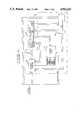
- FIG. 2is a block diagram of the circuit connection of the program counter, and including the control logic that identifies the different operating conditions.
- FIG. 1shows a block diagram of a processor system 11 in accordance with the invention.
- System 11includes an executive memory 17 intermediate user memory 14, compiled user memory 15, a communications interface 18, a bus interface 20 and a keyswitch 21. The foregoing component blocks will be described herein below.
- the system 11also includes scan processor 22 and a math coprocessor 27.
- the scan processor 22scans and executes a ladder logic program stored in the compiled user memory ram 15.
- the math co-processor 27performs the math functions required in response to control from the control processor 12.
- Control processor 12which is of suitable known design, coordinates all processor system 11 operations. This includes performing all communication via a communications interface port and a system bus. Control processor 12 also compiles the ladder program in the compiled user memory and also handles all interrupts and error conditions from the scan processor, system bus, and the remainder of the programmable controller system. In this mode, the scan processor 22 performs computation of output states and register values based upon the current state of inputs and registers; the operations and the sequence in which they are performed is controlled by the program in the compiled user memory. The control processor accesses state and register values accessed from the image memory.
- the intermediate user memory 14 and the compiled user memory 15comprises two distinct portions of memory for maximum efficiency in scanning and program manipulation.
- the intermediate user memory 14is a separate RAM and contains a compiled version of the code which is optimized to serve as executable instructions for the scan processor.
- the program from the intermediate user memory 14is compiled and then downloaded to the compiled user memory 15.
- Compiled user memory 15is implemented with static CMOS devices which are battery backed and parity protected.
- the compiled user memoryprovides 64-bit compiled user program storage for up to 32K words. Each word is comprised of scan processor instructions and control codes, and two 16-bit operands for data or program control.
- the compiled user memoryis randomly accessible by the control processor for purposes of loading and editing user programs.
- the scan processoraccesses the compiled user memory directly as an executive memory of successive instructions. Access by the scan processor is limited to read only operations on the two 16-bit operands when they are coded as immediate data. Branches or subroutines require alteration of the program counter per operand contained in the instruction or scan processor computation.
- the scan processorcontrols its own program counter, which points to the compiled user memory.
- This capabilitypermits the user to utilize subroutines rather than repeated sections of in-line code in his program, for timers and coaunters, etc. By using the same subroutine over and over again for such functions as timers, the amount of required memory to hold this code is greatly reduced.
- FIG. 2is a block diagram indicating communications to the program counter of the scan processor 22 and the control logic identifying various operating commands.
- the program counter 40communicates directly with the compiled user memory 15 and the ALU 42.
- the various command registers in compiled user memory 15are labeled in FIG. 2 and effect control of the program counter 40 through logic control 41.
- the branch operand registers of memory 15couple directly to the program counter 40.
- the executive program that is being executed by the scan processormay be represented as follows:
- Instructions 1 through 10are executed in a continuous loop. Instead of including the entire programming instructions for both subroutine A and B, each time they are required, this code is written only once, and then accessed by the alterable program counter.
- the sequence for this operationwould be as follows:
- the program counter(which contains the address of the next instruction to be executed) is incremented as the sequential instructions of the executive loop are executed.
- the value of the next in-line sequential address for the program counteris stored away in a temporary register called a stack.
- the address in the program counteris then changed to the address of the subroutine.
- the program counteris then incremented sequentially to execute the instructions in the subroutine.
- the subroutine "Return" instructionis encountered, the last address location that was written to the stack is now written into the program counter. This then points the program counter to the instruction in the executive loop that followed the last executive instruction. That last executive instruction was the instruction that directed the program counter to the last executed subroutine.
- the program counterthus continues executive instructions immediately following the last "go to subroutine" instruction.
- the ability to control the program counteralso permits the use of timed or event driven interrupts, which may be generated by intelligent I/O. This is because the interrupt will be handled in the same manner as the subroutines, in that the interrupt code is written as a subroutine, with a "return" terminator.
- the main difference between the subroutines described above, and the interrupt,is that the interrupt routine will be called by a hardware interrupt being generated, rather than an instruction which directs the program counter to the first instructions of the subroutine.
- the scan processorexecutes the user program upon command from the control processor.
- the operation of the scan processoris stopped by a halt command received from the control processor, the execution of a halt instruction, or by parity error detected in either the compiled user memory or image memory.
- This scan processorperforms computation of output states and register values based upon the current state of inputs and registers. The operations and the sequence in which they are performed is controlled by the program contained in the compiled user memory. The I/O states and register values are accessed from the image memory.
- the processor system 11makes use of an image memory to hold the state of all I/O and registers.
- the contents of the image memoryare transferred to the external I/O, and the present I/O state transferred to the image memory, at the end of every scan. Internal registers will not be transferred on the bus.
- the time necessary to do an I/O updateis a function of the number of I/O registers assigned to the system and the degree of register fragmentation. Register fragmentation occurs when there are inputs and outputs in the same register.
- the I/Ocan be allocated in groups of four, registers may contain up to four different I/O groups. During the I/O update, any forcing operations in effect will take place.
- the ladder programis solved after the image memory 16 is set up.
- the programis normally scanned in ascending rung order beginning with rung number 1.
- the image memory 16consists of a battery-backed RAM that provides 16-bit data and status fields for user registers and control registers.
- the image memory 16contains both the internal and external I/O and registers.
- the control processor 12transmits the current values in image memory 16 to the appropriate external devices. It also updates the image memory 16 according to the external I/O and registers in preparation for the next scan. Parity protection is provided for all bytes of the memory.
- the image memory 16 tableis fully accessible by the svcanning processor 22 and control processor 12.
- the control processoris furnished with circuits to interface it to a math co-processor 27.
- This match co-processor 27will perform math functions under the control of the control processor 12 and will free the control processor from this time-consuming task.
- control processorSince the control processor does not scan the ladder program, but has control of the math co-processor 27, the scanning processor 22 must interrupt the control processor 12 for floating point operations. A separate dedicated math co-processor 22 can perform the math operations more efficiently.
- the key-operated selector switch 21allows the control processor 12 to be locked into any one of four operating modes: RUN, RUN PROGRAM, DISABLE or HALT.
- RUNthe control processor 12 scans normally but cannot program
- RUN PROGRAMthe control processor 12 scans normally and the programmer can alter the ladder program.
- HALTthe control processor 12 is not operating on the program; and in the DISABLED OUTPUT mode, the control processor 12 operates on the ladder diagram program, but all external outputs are held in an off state.
- the hardware of the scan processor 22has the ability to distinguish between error conditions which occur when the scan processor is scanning.
- the scan processorreports a specific error code to the control processor to distinguish three categories or types of errors. For example, parity errors can be distinguished in the compiled user memory 15 and in the image memory 16. Also, collision errors, that is indications that the scan processor is receiving illegal commands from the control processor when the scan processor is running, can be distinguished.
- the empty cartonis filled in response to a weight input signal.
- an outputwill be provided to cause a component of the machine to push the full carton away from the loading machine and a second component of the machine to push to empty carton into the loading position to receive the bottles.
- the key switch 21has been set to the RUN mode.
- the user programUpon a clear condition or power up, the user program is loaded into the CMOS RAM area of the intermediate user memory 14. At this time, the control processor 12 transfers this compiled program into the compiled user memory 15.
- the scan processor 22executes the executive program in the compiled user memory 19, and compares input information from the image memory 16 in relation to the instructions in the executive program, it establishes that the carton full state has occurred.
- the scan processor 22now knows that the carton is full, and that an event has occurred which requires an output to do two things, move the carton out of the way and move an empty carton into a loading position.
- the scan processor 22now sets the corresponding output bit in the image memory 16.
- the control processor 12now reads the output bit in the image memory 16 and sends a signal to the output device through bus interface 20.
- the output devicesimultaneously moves the full carton off of the loading position and pushes the empty carton into the loading position.
- the sensor input devicenow detects that there is an empty carton in the loading position (low weight of carton). This information is transmitted through the bus and bus interface 20 to the control processor 12. The control processor 12 then clears the corresponding input bit in the image memory 16. This is only one partial operation of one machine, however the data through the scan processor is evident.
- Some control functionsare math intensified such as input scaling. In a high-speed production situation, the required math calculation could take longer than the necessary scan period of the scan processor 27. In these cases, it is desirable to off-load math calculations to parallel math processor 27 to increase scan rate and not slow the scan rate down by the time taken to do the math calculations. In other words, the math calculations are provided by the math co-processor 27 such as not to reduce the scan rate of the system 11.
Landscapes
- Engineering & Computer Science (AREA)
- Physics & Mathematics (AREA)
- General Physics & Mathematics (AREA)
- Automation & Control Theory (AREA)
- Computer Hardware Design (AREA)
- Theoretical Computer Science (AREA)
- Software Systems (AREA)
- General Engineering & Computer Science (AREA)
- Programmable Controllers (AREA)
- Data Exchanges In Wide-Area Networks (AREA)
- Multi Processors (AREA)
Abstract
Description
______________________________________ EXECUTIVE PROGRAM (Compiled and downloaded to compiled user memory) Address Instruction # Instruction ______________________________________ 0000 1 Instr. 2 Instr. 3 GOSUB A 4 Instr. 5 GOSUB B 6 GOSUB B 7 GOSUB A 8 Instr. 9 GOSUB A NNNN 10 GO TO #1 ______________________________________
______________________________________ SUBROUTINE A SUBROUTINE B ______________________________________ Instr. 1 Instr. 1 Instr. 2 Instr. 2 Instr. 3 Instr. 3 etc. etc. Return Return ______________________________________
______________________________________ INTERRUPT ______________________________________ Instr. 1 Instr. 2 Instr. 3 etc. Halt Instruction ______________________________________
Claims (5)
Priority Applications (10)
| Application Number | Priority Date | Filing Date | Title |
|---|---|---|---|
| US07/179,969US4912623A (en) | 1988-04-11 | 1988-04-11 | Multiple processor communications system |
| CA000596161ACA1337876C (en) | 1988-04-11 | 1989-04-10 | Multiple processor communications system |
| MX015620AMX172627B (en) | 1988-04-11 | 1989-04-11 | IMPROVE MULTIPLE PROCESSOR COMMUNICATION SYSTEM |
| JP1504392AJPH03500701A (en) | 1988-04-11 | 1989-04-11 | multiprocessor communication device |
| PCT/US1989/001515WO1989009968A1 (en) | 1988-04-11 | 1989-04-11 | Multiple processor communications system |
| BR898906811ABR8906811A (en) | 1988-04-11 | 1989-04-11 | PROGRAMMABLE LOGIC CONTROLLER SYSTEM TO CONTROL A NETWORK FOR MACHINE AND PROGRAMMABLE LOGIC CONTROLLER |
| EP19890904419EP0400091A4 (en) | 1988-04-11 | 1989-04-11 | Multiple processor communications system |
| KR1019890702314AKR0146050B1 (en) | 1988-04-11 | 1989-04-11 | Programmable logic controller |
| AU34103/89AAU626854B2 (en) | 1988-04-11 | 1989-04-11 | Multiple processor communications system |
| DK619289ADK619289A (en) | 1988-04-11 | 1989-12-08 | COMMUNICATION SYSTEM WITH MULTIPLE PROCESSORS |
Applications Claiming Priority (1)
| Application Number | Priority Date | Filing Date | Title |
|---|---|---|---|
| US07/179,969US4912623A (en) | 1988-04-11 | 1988-04-11 | Multiple processor communications system |
Publications (1)
| Publication Number | Publication Date |
|---|---|
| US4912623Atrue US4912623A (en) | 1990-03-27 |
Family
ID=22658746
Family Applications (1)
| Application Number | Title | Priority Date | Filing Date |
|---|---|---|---|
| US07/179,969Expired - LifetimeUS4912623A (en) | 1988-04-11 | 1988-04-11 | Multiple processor communications system |
Country Status (9)
| Country | Link |
|---|---|
| US (1) | US4912623A (en) |
| EP (1) | EP0400091A4 (en) |
| JP (1) | JPH03500701A (en) |
| KR (1) | KR0146050B1 (en) |
| AU (1) | AU626854B2 (en) |
| BR (1) | BR8906811A (en) |
| CA (1) | CA1337876C (en) |
| MX (1) | MX172627B (en) |
| WO (1) | WO1989009968A1 (en) |
Cited By (53)
| Publication number | Priority date | Publication date | Assignee | Title |
|---|---|---|---|---|
| US5225974A (en)* | 1990-10-30 | 1993-07-06 | Allen-Bradley Company, Inc. | Programmable controller processor with an intelligent functional module interface |
| US5251302A (en)* | 1988-04-11 | 1993-10-05 | Square D Company | Network interface board having memory mapped mailbox registers including alarm registers for storing prioritized alarm messages from programmable logic controllers |
| US5594917A (en)* | 1992-10-19 | 1997-01-14 | Siemens Energy & Automation, Inc. | High speed programmable logic controller |
| US5706627A (en)* | 1994-02-02 | 1998-01-13 | Tetra Laval Holdings & Finance, S.A. | Control system for a packaging machine |
| US5724786A (en)* | 1994-09-28 | 1998-03-10 | Tetra Laval Holdings & Finance S.A. | Control system having error correcting apparatus |
| US6233626B1 (en) | 1998-10-06 | 2001-05-15 | Schneider Automation Inc. | System for a modular terminal input/output interface for communicating messaging application layer over encoded ethernet to transport layer |
| US6282454B1 (en) | 1997-09-10 | 2001-08-28 | Schneider Automation Inc. | Web interface to a programmable controller |
| US6327511B1 (en) | 1998-12-30 | 2001-12-04 | Schneider Automation, Inc. | Input/output (I/O) scanner for a control system with peer determination |
| US20020091784A1 (en)* | 1997-09-10 | 2002-07-11 | Baker Richard A. | Web interface to a device and an electrical network control system |
| US6434157B1 (en) | 1998-10-06 | 2002-08-13 | Schneider Automation, Inc. | MODBUS plus ethernet bridge |
| US20020169844A1 (en)* | 2000-09-06 | 2002-11-14 | Schneider Electric | Method and apparatus for ethernet prioritized device clock synchronization |
| US20020167967A1 (en)* | 2000-09-06 | 2002-11-14 | Schneider Electric | Method for managing bandwidth on an ethernet network |
| US20020194365A1 (en)* | 1998-03-16 | 2002-12-19 | Francois Jammes | Communication system for a control system over ethernet and IP networks |
| US20030033030A1 (en)* | 2000-07-07 | 2003-02-13 | Ron Naismith | Input/output (I/O) scanner for a control system with peer determination |
| US20030139821A1 (en)* | 1997-09-10 | 2003-07-24 | Papadopoulos A. Dean | System and method for interfacing with a controller |
| US20030140928A1 (en)* | 2002-01-29 | 2003-07-31 | Tuan Bui | Medical treatment verification system and method |
| US20030204419A1 (en)* | 2002-04-30 | 2003-10-30 | Wilkes Gordon J. | Automated messaging center system and method for use with a healthcare system |
| US20030225596A1 (en)* | 2002-05-31 | 2003-12-04 | Richardson Bill R. | Biometric security for access to a storage device for a healthcare facility |
| US6732191B1 (en) | 1997-09-10 | 2004-05-04 | Schneider Automation Inc. | Web interface to an input/output device |
| US20040172222A1 (en)* | 2002-01-29 | 2004-09-02 | Simpson Thomas L. C. | System and method for notification and escalation of medical data |
| US20040210629A1 (en)* | 1998-12-30 | 2004-10-21 | Klindt Charles J. | Interface to a programmable logic controller |
| US20040210664A1 (en)* | 2003-04-17 | 2004-10-21 | Schneider Automation Inc. | System and method for transmitting data |
| US6845401B1 (en) | 1998-12-30 | 2005-01-18 | Schneider Automation Inc. | Embedded file system for a programmable logic controller |
| US20050081107A1 (en)* | 2003-10-09 | 2005-04-14 | International Business Machines Corporation | Method and system for autonomic execution path selection in an application |
| US7023795B1 (en) | 2000-11-07 | 2006-04-04 | Schneider Automation Inc. | Method and apparatus for an active standby control system on a network |
| US7032029B1 (en) | 2000-07-07 | 2006-04-18 | Schneider Automation Inc. | Method and apparatus for an active standby control system on a network |
| US7035898B1 (en) | 1997-09-10 | 2006-04-25 | Schneider Automation Inc. | System for programming a factory automation device using a web browser |
| US7058693B1 (en) | 1997-09-10 | 2006-06-06 | Schneider Automation Inc. | System for programming a programmable logic controller using a web browser |
| US7146408B1 (en) | 1996-05-30 | 2006-12-05 | Schneider Automation Inc. | Method and system for monitoring a controller and displaying data from the controller in a format provided by the controller |
| US7181487B1 (en) | 2000-07-07 | 2007-02-20 | Schneider Automation Inc. | Method and system for transmitting and activating an application requesting human intervention in an automation network |
| CN102540954A (en)* | 2010-12-24 | 2012-07-04 | 深圳市合信自动化技术有限公司 | Programmable logic controller and control method thereof |
| CN102540953A (en)* | 2010-12-24 | 2012-07-04 | 深圳市合信自动化技术有限公司 | Programmable logic controller and data processing method thereof |
| US8234128B2 (en) | 2002-04-30 | 2012-07-31 | Baxter International, Inc. | System and method for verifying medical device operational parameters |
| US20130211545A1 (en)* | 2011-08-11 | 2013-08-15 | Siemens Aktiengesellschaft | Embedded Multi-Processor Parallel Processing System and Operating Method for Same |
| US8615619B2 (en) | 2004-01-14 | 2013-12-24 | International Business Machines Corporation | Qualifying collection of performance monitoring events by types of interrupt when interrupt occurs |
| US8689190B2 (en) | 2003-09-30 | 2014-04-01 | International Business Machines Corporation | Counting instruction execution and data accesses |
| US8782664B2 (en) | 2004-01-14 | 2014-07-15 | International Business Machines Corporation | Autonomic hardware assist for patching code |
| US10016554B2 (en) | 2008-07-09 | 2018-07-10 | Baxter International Inc. | Dialysis system including wireless patient data |
| US10061899B2 (en) | 2008-07-09 | 2018-08-28 | Baxter International Inc. | Home therapy machine |
| US10173008B2 (en) | 2002-01-29 | 2019-01-08 | Baxter International Inc. | System and method for communicating with a dialysis machine through a network |
| US10347374B2 (en) | 2008-10-13 | 2019-07-09 | Baxter Corporation Englewood | Medication preparation system |
| US10552577B2 (en) | 2012-08-31 | 2020-02-04 | Baxter Corporation Englewood | Medication requisition fulfillment system and method |
| US10646405B2 (en) | 2012-10-26 | 2020-05-12 | Baxter Corporation Englewood | Work station for medical dose preparation system |
| US10818387B2 (en) | 2014-12-05 | 2020-10-27 | Baxter Corporation Englewood | Dose preparation data analytics |
| US10971257B2 (en) | 2012-10-26 | 2021-04-06 | Baxter Corporation Englewood | Image acquisition for medical dose preparation system |
| US20210150359A1 (en)* | 2018-08-03 | 2021-05-20 | Siemens Aktiengesellschaft | Neural logic controllers |
| US11107574B2 (en) | 2014-09-30 | 2021-08-31 | Baxter Corporation Englewood | Management of medication preparation with formulary management |
| US11367533B2 (en) | 2014-06-30 | 2022-06-21 | Baxter Corporation Englewood | Managed medical information exchange |
| US11495334B2 (en) | 2015-06-25 | 2022-11-08 | Gambro Lundia Ab | Medical device system and method having a distributed database |
| US11516183B2 (en) | 2016-12-21 | 2022-11-29 | Gambro Lundia Ab | Medical device system including information technology infrastructure having secure cluster domain supporting external domain |
| US11575673B2 (en) | 2014-09-30 | 2023-02-07 | Baxter Corporation Englewood | Central user management in a distributed healthcare information management system |
| US11948112B2 (en) | 2015-03-03 | 2024-04-02 | Baxter Corporation Engelwood | Pharmacy workflow management with integrated alerts |
| US12412644B2 (en) | 2014-10-24 | 2025-09-09 | Baxter Corporation Englewood | Automated exchange of healthcare information for fulfillment of medication doses |
Families Citing this family (2)
| Publication number | Priority date | Publication date | Assignee | Title |
|---|---|---|---|---|
| JPH03288906A (en)* | 1990-04-05 | 1991-12-19 | Fanuc Ltd | Instruction executing system for pc |
| KR100395743B1 (en)* | 1995-10-27 | 2003-11-28 | 삼성중공업 주식회사 | Interface method of distributed control system and hybrid programmer controller |
Citations (8)
| Publication number | Priority date | Publication date | Assignee | Title |
|---|---|---|---|---|
| US3689895A (en)* | 1969-11-24 | 1972-09-05 | Nippon Electric Co | Micro-program control system |
| US4118789A (en)* | 1977-06-06 | 1978-10-03 | Allen-Bradley Company | Program protection module for programmable controller |
| US4165534A (en)* | 1977-04-25 | 1979-08-21 | Allen-Bradley Company | Digital control system with Boolean processor |
| US4200915A (en)* | 1978-04-05 | 1980-04-29 | Allen-Bradley Company | Program loader for programmable controller |
| US4215397A (en)* | 1978-08-24 | 1980-07-29 | Texas Instruments Incorporated | Automatic end-of-scan control system for a programmable process controller with expandable memory |
| DE3241357A1 (en)* | 1982-11-09 | 1984-05-10 | Siemens AG, 1000 Berlin und 8000 München | DEVICE FOR PROVIDING MICRO COMMANDS FOR AT LEAST TWO INDEPENDENTLY WORKING FUNCTIONAL UNITS IN AN INTEGRATED, MICROPROGRAMMED ELECTRONIC MODULE AND METHOD FOR THEIR OPERATION |
| US4646289A (en)* | 1984-06-29 | 1987-02-24 | Northern Telecom Limited | Signal multiplexing circuit |
| US4716541A (en)* | 1984-08-02 | 1987-12-29 | Quatse Jesse T | Boolean processor for a progammable controller |
- 1988
- 1988-04-11USUS07/179,969patent/US4912623A/ennot_activeExpired - Lifetime
- 1989
- 1989-04-10CACA000596161Apatent/CA1337876C/ennot_activeExpired - Fee Related
- 1989-04-11KRKR1019890702314Apatent/KR0146050B1/ennot_activeExpired - Fee Related
- 1989-04-11BRBR898906811Apatent/BR8906811A/enunknown
- 1989-04-11MXMX015620Apatent/MX172627B/enunknown
- 1989-04-11EPEP19890904419patent/EP0400091A4/ennot_activeWithdrawn
- 1989-04-11AUAU34103/89Apatent/AU626854B2/ennot_activeCeased
- 1989-04-11WOPCT/US1989/001515patent/WO1989009968A1/ennot_activeApplication Discontinuation
- 1989-04-11JPJP1504392Apatent/JPH03500701A/enactivePending
Patent Citations (8)
| Publication number | Priority date | Publication date | Assignee | Title |
|---|---|---|---|---|
| US3689895A (en)* | 1969-11-24 | 1972-09-05 | Nippon Electric Co | Micro-program control system |
| US4165534A (en)* | 1977-04-25 | 1979-08-21 | Allen-Bradley Company | Digital control system with Boolean processor |
| US4118789A (en)* | 1977-06-06 | 1978-10-03 | Allen-Bradley Company | Program protection module for programmable controller |
| US4200915A (en)* | 1978-04-05 | 1980-04-29 | Allen-Bradley Company | Program loader for programmable controller |
| US4215397A (en)* | 1978-08-24 | 1980-07-29 | Texas Instruments Incorporated | Automatic end-of-scan control system for a programmable process controller with expandable memory |
| DE3241357A1 (en)* | 1982-11-09 | 1984-05-10 | Siemens AG, 1000 Berlin und 8000 München | DEVICE FOR PROVIDING MICRO COMMANDS FOR AT LEAST TWO INDEPENDENTLY WORKING FUNCTIONAL UNITS IN AN INTEGRATED, MICROPROGRAMMED ELECTRONIC MODULE AND METHOD FOR THEIR OPERATION |
| US4646289A (en)* | 1984-06-29 | 1987-02-24 | Northern Telecom Limited | Signal multiplexing circuit |
| US4716541A (en)* | 1984-08-02 | 1987-12-29 | Quatse Jesse T | Boolean processor for a progammable controller |
Cited By (74)
| Publication number | Priority date | Publication date | Assignee | Title |
|---|---|---|---|---|
| US5251302A (en)* | 1988-04-11 | 1993-10-05 | Square D Company | Network interface board having memory mapped mailbox registers including alarm registers for storing prioritized alarm messages from programmable logic controllers |
| US5225974A (en)* | 1990-10-30 | 1993-07-06 | Allen-Bradley Company, Inc. | Programmable controller processor with an intelligent functional module interface |
| US5594917A (en)* | 1992-10-19 | 1997-01-14 | Siemens Energy & Automation, Inc. | High speed programmable logic controller |
| US5706627A (en)* | 1994-02-02 | 1998-01-13 | Tetra Laval Holdings & Finance, S.A. | Control system for a packaging machine |
| US5966897A (en)* | 1994-02-02 | 1999-10-19 | Tetra Laval Holdings & Finance, Sa | Control system for a packaging machine |
| US5724786A (en)* | 1994-09-28 | 1998-03-10 | Tetra Laval Holdings & Finance S.A. | Control system having error correcting apparatus |
| US7146408B1 (en) | 1996-05-30 | 2006-12-05 | Schneider Automation Inc. | Method and system for monitoring a controller and displaying data from the controller in a format provided by the controller |
| US20020091784A1 (en)* | 1997-09-10 | 2002-07-11 | Baker Richard A. | Web interface to a device and an electrical network control system |
| US6732191B1 (en) | 1997-09-10 | 2004-05-04 | Schneider Automation Inc. | Web interface to an input/output device |
| US8291121B2 (en) | 1997-09-10 | 2012-10-16 | Square D Company | System and method for interfacing with a controller |
| US7035898B1 (en) | 1997-09-10 | 2006-04-25 | Schneider Automation Inc. | System for programming a factory automation device using a web browser |
| US7058693B1 (en) | 1997-09-10 | 2006-06-06 | Schneider Automation Inc. | System for programming a programmable logic controller using a web browser |
| US6282454B1 (en) | 1997-09-10 | 2001-08-28 | Schneider Automation Inc. | Web interface to a programmable controller |
| US20030139821A1 (en)* | 1997-09-10 | 2003-07-24 | Papadopoulos A. Dean | System and method for interfacing with a controller |
| US20020194365A1 (en)* | 1998-03-16 | 2002-12-19 | Francois Jammes | Communication system for a control system over ethernet and IP networks |
| US7162510B2 (en) | 1998-03-16 | 2007-01-09 | Schneider Automation Inc. | Communication system for a control system over Ethernet and IP networks |
| US6233626B1 (en) | 1998-10-06 | 2001-05-15 | Schneider Automation Inc. | System for a modular terminal input/output interface for communicating messaging application layer over encoded ethernet to transport layer |
| US7590702B2 (en) | 1998-10-06 | 2009-09-15 | Schneider Automation Inc. | Messaging application layer over ethernet to transport layer (TCP) communications method and apparatus for a modular terminal input/output system |
| US6466995B2 (en) | 1998-10-06 | 2002-10-15 | Schneider Automation, Inc. | Messaging application layer over ethernet to transport layer (TCP) communications method and apparatus for a modular terminal input/output system |
| US6434157B1 (en) | 1998-10-06 | 2002-08-13 | Schneider Automation, Inc. | MODBUS plus ethernet bridge |
| US6327511B1 (en) | 1998-12-30 | 2001-12-04 | Schneider Automation, Inc. | Input/output (I/O) scanner for a control system with peer determination |
| US7062335B2 (en) | 1998-12-30 | 2006-06-13 | Schneider Automation Inc. | Interface to a programmable logic controller |
| US6853867B1 (en) | 1998-12-30 | 2005-02-08 | Schneider Automation Inc. | Interface to a programmable logic controller |
| US20040210629A1 (en)* | 1998-12-30 | 2004-10-21 | Klindt Charles J. | Interface to a programmable logic controller |
| US6845401B1 (en) | 1998-12-30 | 2005-01-18 | Schneider Automation Inc. | Embedded file system for a programmable logic controller |
| US20030033030A1 (en)* | 2000-07-07 | 2003-02-13 | Ron Naismith | Input/output (I/O) scanner for a control system with peer determination |
| US7032029B1 (en) | 2000-07-07 | 2006-04-18 | Schneider Automation Inc. | Method and apparatus for an active standby control system on a network |
| US7181487B1 (en) | 2000-07-07 | 2007-02-20 | Schneider Automation Inc. | Method and system for transmitting and activating an application requesting human intervention in an automation network |
| US7519737B2 (en) | 2000-07-07 | 2009-04-14 | Schneider Automation Inc. | Input/output (I/O) scanner for a control system with peer determination |
| US7028204B2 (en) | 2000-09-06 | 2006-04-11 | Schneider Automation Inc. | Method and apparatus for ethernet prioritized device clock synchronization |
| US20020167967A1 (en)* | 2000-09-06 | 2002-11-14 | Schneider Electric | Method for managing bandwidth on an ethernet network |
| US20020169844A1 (en)* | 2000-09-06 | 2002-11-14 | Schneider Electric | Method and apparatus for ethernet prioritized device clock synchronization |
| US7023795B1 (en) | 2000-11-07 | 2006-04-04 | Schneider Automation Inc. | Method and apparatus for an active standby control system on a network |
| US8775196B2 (en) | 2002-01-29 | 2014-07-08 | Baxter International Inc. | System and method for notification and escalation of medical data |
| US10173008B2 (en) | 2002-01-29 | 2019-01-08 | Baxter International Inc. | System and method for communicating with a dialysis machine through a network |
| US20040172222A1 (en)* | 2002-01-29 | 2004-09-02 | Simpson Thomas L. C. | System and method for notification and escalation of medical data |
| US10556062B2 (en) | 2002-01-29 | 2020-02-11 | Baxter International Inc. | Electronic medication order transfer and processing methods and apparatus |
| US20030140928A1 (en)* | 2002-01-29 | 2003-07-31 | Tuan Bui | Medical treatment verification system and method |
| US20030204419A1 (en)* | 2002-04-30 | 2003-10-30 | Wilkes Gordon J. | Automated messaging center system and method for use with a healthcare system |
| US8234128B2 (en) | 2002-04-30 | 2012-07-31 | Baxter International, Inc. | System and method for verifying medical device operational parameters |
| US20030225596A1 (en)* | 2002-05-31 | 2003-12-04 | Richardson Bill R. | Biometric security for access to a storage device for a healthcare facility |
| US20040210664A1 (en)* | 2003-04-17 | 2004-10-21 | Schneider Automation Inc. | System and method for transmitting data |
| US8689190B2 (en) | 2003-09-30 | 2014-04-01 | International Business Machines Corporation | Counting instruction execution and data accesses |
| US8381037B2 (en)* | 2003-10-09 | 2013-02-19 | International Business Machines Corporation | Method and system for autonomic execution path selection in an application |
| US20050081107A1 (en)* | 2003-10-09 | 2005-04-14 | International Business Machines Corporation | Method and system for autonomic execution path selection in an application |
| US8782664B2 (en) | 2004-01-14 | 2014-07-15 | International Business Machines Corporation | Autonomic hardware assist for patching code |
| US8615619B2 (en) | 2004-01-14 | 2013-12-24 | International Business Machines Corporation | Qualifying collection of performance monitoring events by types of interrupt when interrupt occurs |
| US10224117B2 (en) | 2008-07-09 | 2019-03-05 | Baxter International Inc. | Home therapy machine allowing patient device program selection |
| US11311658B2 (en) | 2008-07-09 | 2022-04-26 | Baxter International Inc. | Dialysis system having adaptive prescription generation |
| US10016554B2 (en) | 2008-07-09 | 2018-07-10 | Baxter International Inc. | Dialysis system including wireless patient data |
| US10061899B2 (en) | 2008-07-09 | 2018-08-28 | Baxter International Inc. | Home therapy machine |
| US10068061B2 (en) | 2008-07-09 | 2018-09-04 | Baxter International Inc. | Home therapy entry, modification, and reporting system |
| US11918721B2 (en) | 2008-07-09 | 2024-03-05 | Baxter International Inc. | Dialysis system having adaptive prescription management |
| US10095840B2 (en) | 2008-07-09 | 2018-10-09 | Baxter International Inc. | System and method for performing renal therapy at a home or dwelling of a patient |
| US10646634B2 (en) | 2008-07-09 | 2020-05-12 | Baxter International Inc. | Dialysis system and disposable set |
| US10272190B2 (en) | 2008-07-09 | 2019-04-30 | Baxter International Inc. | Renal therapy system including a blood pressure monitor |
| US10347374B2 (en) | 2008-10-13 | 2019-07-09 | Baxter Corporation Englewood | Medication preparation system |
| CN102540954B (en)* | 2010-12-24 | 2015-03-11 | 深圳市合信自动化技术有限公司 | Programmable logic controller and control method thereof |
| CN102540954A (en)* | 2010-12-24 | 2012-07-04 | 深圳市合信自动化技术有限公司 | Programmable logic controller and control method thereof |
| CN102540953A (en)* | 2010-12-24 | 2012-07-04 | 深圳市合信自动化技术有限公司 | Programmable logic controller and data processing method thereof |
| US20130211545A1 (en)* | 2011-08-11 | 2013-08-15 | Siemens Aktiengesellschaft | Embedded Multi-Processor Parallel Processing System and Operating Method for Same |
| US10089443B2 (en) | 2012-05-15 | 2018-10-02 | Baxter International Inc. | Home medical device systems and methods for therapy prescription and tracking, servicing and inventory |
| US10552577B2 (en) | 2012-08-31 | 2020-02-04 | Baxter Corporation Englewood | Medication requisition fulfillment system and method |
| US10646405B2 (en) | 2012-10-26 | 2020-05-12 | Baxter Corporation Englewood | Work station for medical dose preparation system |
| US10971257B2 (en) | 2012-10-26 | 2021-04-06 | Baxter Corporation Englewood | Image acquisition for medical dose preparation system |
| US11367533B2 (en) | 2014-06-30 | 2022-06-21 | Baxter Corporation Englewood | Managed medical information exchange |
| US11107574B2 (en) | 2014-09-30 | 2021-08-31 | Baxter Corporation Englewood | Management of medication preparation with formulary management |
| US11575673B2 (en) | 2014-09-30 | 2023-02-07 | Baxter Corporation Englewood | Central user management in a distributed healthcare information management system |
| US12412644B2 (en) | 2014-10-24 | 2025-09-09 | Baxter Corporation Englewood | Automated exchange of healthcare information for fulfillment of medication doses |
| US10818387B2 (en) | 2014-12-05 | 2020-10-27 | Baxter Corporation Englewood | Dose preparation data analytics |
| US11948112B2 (en) | 2015-03-03 | 2024-04-02 | Baxter Corporation Engelwood | Pharmacy workflow management with integrated alerts |
| US11495334B2 (en) | 2015-06-25 | 2022-11-08 | Gambro Lundia Ab | Medical device system and method having a distributed database |
| US11516183B2 (en) | 2016-12-21 | 2022-11-29 | Gambro Lundia Ab | Medical device system including information technology infrastructure having secure cluster domain supporting external domain |
| US20210150359A1 (en)* | 2018-08-03 | 2021-05-20 | Siemens Aktiengesellschaft | Neural logic controllers |
Also Published As
| Publication number | Publication date |
|---|---|
| EP0400091A4 (en) | 1993-03-03 |
| MX172627B (en) | 1994-01-04 |
| WO1989009968A1 (en) | 1989-10-19 |
| BR8906811A (en) | 1990-11-13 |
| JPH03500701A (en) | 1991-02-14 |
| EP0400091A1 (en) | 1990-12-05 |
| CA1337876C (en) | 1996-01-02 |
| KR900700965A (en) | 1990-08-17 |
| AU626854B2 (en) | 1992-08-13 |
| KR0146050B1 (en) | 1998-09-15 |
| AU3410389A (en) | 1989-11-03 |
Similar Documents
| Publication | Publication Date | Title |
|---|---|---|
| US4912623A (en) | Multiple processor communications system | |
| EP0586813B1 (en) | Programmable controller with ladder diagram macro instructions | |
| US4486830A (en) | Programmable control apparatus and method | |
| US4972365A (en) | Executing downloaded user programs in a programmable controller | |
| US4415965A (en) | Programmable sequence controller | |
| US4918589A (en) | Method and apparatus for linking processors in a hierarchical control system | |
| US5619409A (en) | Program analysis circuitry for multi-tasking industrial controller | |
| CA1144655A (en) | Mini-programmable controller | |
| US4314354A (en) | Memory programmable control | |
| US5623401A (en) | Industrial controller with optimized execution of relay ladder logic programs | |
| WO1993019409A1 (en) | Programmable controller with fast i/o scan | |
| EP0378415A3 (en) | Multiple instruction dispatch mechanism | |
| US4627025A (en) | Memory programmable controller with word and bit processors | |
| US4396973A (en) | Programmable sequence controller | |
| EP0381600A2 (en) | Robotic workcell control system with a binary accelerator providing enhanced binary calculations | |
| EP0377939A1 (en) | Robot control system for controlling a set of industrial robots | |
| EP0397414B1 (en) | Control device having a function of modifying a microinstruction | |
| EP0299075A1 (en) | Processing unit having at least one coprocessor | |
| US3470537A (en) | Information processing system using relative addressing | |
| KR100301391B1 (en) | Subroutine branch instruction execution method and device | |
| EP0407612B1 (en) | External extension type programmable controller | |
| Naur | Machine dependent programming in common languages | |
| EP0445288A1 (en) | Operation processing unit | |
| KR900005548B1 (en) | Programmble controller | |
| JP2510691B2 (en) | Arithmetic processing method |
Legal Events
| Date | Code | Title | Description |
|---|---|---|---|
| AS | Assignment | Owner name:SQUARE D COMPANY, A MI CORP., MICHIGAN Free format text:ASSIGNMENT OF ASSIGNORS INTEREST.;ASSIGNOR:GATES, DIRK I.;REEL/FRAME:005046/0773 Effective date:19880517 Owner name:SQUARE D COMPANY, A MI CORP., MICHIGAN Free format text:ASSIGNMENT OF ASSIGNORS INTEREST.;ASSIGNORS:RANATAL, GLEN W.;JANKE, DONALD R.;REEL/FRAME:005046/0771 Effective date:19880426 Owner name:SQUARE D COMPANY, A MI CORP., MICHIGAN Free format text:ASSIGNMENT OF ASSIGNORS INTEREST.;ASSIGNOR:WATT, KIM J.;REEL/FRAME:005046/0772 Effective date:19880422 | |
| STCF | Information on status: patent grant | Free format text:PATENTED CASE | |
| FPAY | Fee payment | Year of fee payment:4 | |
| AS | Assignment | Owner name:MODICON, INC., MASSACHUSETTS Free format text:ASSIGNMENT OF ASSIGNORS INTEREST;ASSIGNOR:SQUARE D COMPANY;REEL/FRAME:007235/0131 Effective date:19941014 | |
| AS | Assignment | Owner name:AEG SCHNEIDER AUTOMATION, INC. Free format text:CHANGE OF NAME;ASSIGNOR:MODICON, INC.;REEL/FRAME:007397/0801 Effective date:19941014 | |
| AS | Assignment | Owner name:SCHNEIDER AUTOMATION INC., MASSACHUSETTS Free format text:CHANGE OF NAME;ASSIGNOR:AEG SCHNEIDER AUTOMATION, INC.;REEL/FRAME:008855/0799 Effective date:19960801 | |
| REMI | Maintenance fee reminder mailed | ||
| FPAY | Fee payment | Year of fee payment:8 | |
| SULP | Surcharge for late payment | ||
| FPAY | Fee payment | Year of fee payment:12 |