US4912443A - Superconducting magnetic energy storage inductor and method of manufacture - Google Patents
Superconducting magnetic energy storage inductor and method of manufactureDownload PDFInfo
- Publication number
- US4912443A US4912443AUS07/306,363US30636389AUS4912443AUS 4912443 AUS4912443 AUS 4912443AUS 30636389 AUS30636389 AUS 30636389AUS 4912443 AUS4912443 AUS 4912443A
- Authority
- US
- United States
- Prior art keywords
- conductor
- coil
- support
- sheath
- radial
- Prior art date
- Legal status (The legal status is an assumption and is not a legal conclusion. Google has not performed a legal analysis and makes no representation as to the accuracy of the status listed.)
- Expired - Lifetime
Links
Images

Classifications
- H—ELECTRICITY
- H01—ELECTRIC ELEMENTS
- H01F—MAGNETS; INDUCTANCES; TRANSFORMERS; SELECTION OF MATERIALS FOR THEIR MAGNETIC PROPERTIES
- H01F6/00—Superconducting magnets; Superconducting coils
- H01F6/06—Coils, e.g. winding, insulating, terminating or casing arrangements therefor
Definitions
- the present inventionrelates to superconducting magnetic energy storage devices, particularly in the form of solenoid coils which are installed in annular enclosures, possibly below ground.
- the superconductive materials which are currently usable in practicesuch as NbTi, must be maintained at a temperature in the vicinity of 1°-4° K. in order to exhibit superconducting properties. Such temperatures can be established by surrounding the superconducting material with successive envelopes of cryogens having progressively higher boiling points.
- an envelope of heliumwhich can be made to have a boiling point lower than 4° K., surrounded by an envelope of neon, having a boiling point of in the vicinity of 28° K., the latter being surrounded by an envelope of nitrogen, having a boiling point in the vicinity of 77° K.
- an envelope of heliumwhich can be made to have a boiling point lower than 4° K., surrounded by an envelope of neon, having a boiling point of in the vicinity of 28° K., the latter being surrounded by an envelope of nitrogen, having a boiling point in the vicinity of 77° K.
- known structures for supporting such conductorsenable the conductors to contact liquid helium only over a limited portion of their circumference, typically of the order of a quarter of their circumference. This makes it difficult to maintain the entire conductor at its superconducting temperature, particularly when conditions occur which cause the cryogen in contact with the conductors to experience a transition from the super fluid state to a two-phase boiling heat transfer condition.
- the coil support structureswhich have already been proposed attempt to deal with the problems of radial contraction stresses during cooldown to superconductive temperatures in ways which cause slipping movements which generate heat due to friction and/or which induce high bending stresses and/or which require the creation of a loose coil pack which will experience insulation abrasion and movement during operation of the coil.
- Another object of the inventionis to provide a conductor support structure which will provide a high degree of support for the novel conductor while allowing intimate contact between the liquid cryogen and the entire circumferential region of the conductor.
- a further object of the inventionis to provide radial support for an assembled coil which will impose only small radial compression forces on the coil during operation at cryogenic temperatures.
- a conductor for a superconducting coilcomprising a plurality of strands twisted together to form a cylindrical structure, and each strand comprising:
- a corecomposed of a plurality of parallel filaments of a material capable of exhibiting superconductivity
- a tubular member of high purity aluminumenclosing the sheath so as to be in intimate electrical contact with the sheath and support the core.
- Objects according to the inventionare further achieved by a method of fabricating the above-described conductor for a superconducting coil comprising:
- forming a conductor strandby: providing a core composed of a plurality of parallel filaments of a material capable of exhibiting superconducting; forming a sheath of metal around the core and radially compressing the sheath against the core to form a matrix in which at least some of the filaments are embedded; and placing the sheath into a C-shaped stabilizer member and then bending the member into the form of a closed tube which is pressed radially against the sheath; and
- a support for a superconducting conductorwhich is to be immersed in a liquid cryogen, comprising: a support plate having one exterior surface which is to be in contact with the cryogen, and formed to present a U-shaped conductor support channel spaced inwardly from the one exterior surface; and a conductor compression wedge arranged to be inserted in the channel for holding the conductor in place in the channel.
- Objects according to the inventionare further achieved by a method for securing a superconducting solenoid coil in an annular enclosure having interior and exterior side walls, the coil experiencing radial contraction forces when being cooled from environmental temperature to cryogenic temperature, the method comprising, in the order recited:
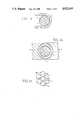
- FIG. 1ais a cross-sectional view of an initial stage in the fabrication of a conductor according to the present invention.
- FIG. 1bis a cross-sectional view of a subsequent stage in the fabrication of the conductor.
- FIG. 1cis an end view of a completed conductor according to the present invention.
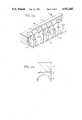
- FIG. 2ais an exploded, perspective view of a preferred embodiment of a conductor support structure according to the present invention.
- FIG. 2bis a cross-sectional view taken along the plane B--B of FIG. 2a.
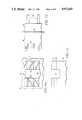
- FIG. 3is a cross-sectional view of a portion of a coil structure according to the present invention.
- FIG. 4ais a detailed, front-elevational view of a portion of a coil support system according to the invention.
- FIG. 4bis a side-elevational view of the structure shown in FIG. 4a.
- FIG. 4cis a plan view of the structure shown in FIG. 4a.
- FIGS. 1a, 1b and 1cillustrate three stages in the fabrication of one conductor according to the present invention.
- a large number of filaments of a superconductive materialsuch as NbTi, each filament having a diameter of the order of 20 microns, are twisted together to form a core 2 which is then encased in a copper matrix 4 by an extrusion operation which causes the material matrix 4 to fill most of the spaces between the NbTi filament.
- Matrix 4is solder coated and introduced into a stabilizer piece 6 which initially has a C-shape.
- Stabilizer piece 6is made of a high purity aluminum which is solder coated.
- these surfacescan be silver plated to produce the desired conductive electrical contact therebetween.
- FIG. 1billustrates an intermediate point in this process.
- the resulting assemblywhich constitutes a single superconductor strand 10 is heated to effect annealing and completion of the solder bond between matrix 4 and stabilizer 6.
- the resulting strand 10can be heat treated in an oxygen atmosphere in order to form an insulating layer of aluminum oxide on the outer surface of piece 6.
- core 2For use in a large coil, core 2 would have a diameter of the order of 3 mm and matrix 4 would have a diameter of the order of 5.5 mm.
- strands 10are twisted together in a fully transposed manner to form a completed conductor having a hollow center 12.
- strands 10can be wrapped around a hollow tube of aluminum, which can remain in place or be withdrawn after formation of strand 10, or can be twisted without such hollow tube.
- each strand 10will minimize current flow between adjacent strands and the resulting conductor will have low losses.
- the insulating layer on the outer surface of each strand 10serves to increase the effective resistance of the conductor to eddy currents. This can also be achieved by reducing the diameter of each strand 10 and increasing the total number of strands 10 in the conductor.
- the twist pitch of the resulting conductoris selected to limit the strain in the conductor to an acceptable value during operation of the inductor which is formed by coiling the conductor.
- a tight twist pitchwill cause the conductor to behave like a coiled spring which will allow relatively large changes in the effective length the conductor, corresponding to changes in the diameter of the coil, without significantly increasing the strain experienced by the individual strands 10.
- a twist pitch of 1 m or lessis envisioned.
- the increased strain tolerance of the resulting conductorreduces its load bearing capability. Therefore, the conductor must be adequately supported, particularly in order to withstand the electromagnetic forces that will exist in the resulting coil, while providing effective thermal communication between the conductor and the cryogen, such as helium, employed to maintain the conductor at a superconducting temperature.
- cryogensuch as helium
- FIG. 2aA conductor support structure according to the present invention, which is capable of performing these functions, is illustrated, in exploded form, in FIG. 2a.
- This structureincludes a support plate 16 and a conductor compression wedge 18 between which the conductor shown in FIG. 1c will be clamped.
- Support plate 16is provided with an upwardly extending U-shaped channel 20 in which the conductor will rest.
- This channelincludes, along its length, conductor support regions 22 alternating with channel regions 24 for the circulation of liquid helium around the conductor.
- Compression wedge 18includes corresponding conductor engaging regions 26 alternating with channel regions 28 which will cooperate with channel 24 to provide liquid helium flow paths which circulate around the conductor periphery. As shown in FIG.
- compression wedge 18is provided, in each channel region 88, with a sloping surface 30 for preventing helium bubble stagnation in the channels.
- the channels formed by regions 24 and 28are spaced 2-10 cm apart along the length of the support structure.
- the complete support structure for a coilwould be composed of a plurality of the structures shown in FIG. 2a joined together in abutting relationship along the length of the conductor.
- FIG. 3is a cross-sectional detail view taken in a vertical plane which passes through the coil axis.
- each conductor 32 and 34In the coil, current is carried by two conductors 32 and 34 which are spaced apart radially. Each conductor is formed into a large number of turns which are spaced apart vertically, or axially, along the coil. Each of conductors 32 and 34 has the structure shown in FIG. 1c. Conductors 32 and 34 are supported by supports composed of support plates 16 and compression wedges 18, constructed as shown in FIGS. 2. For supporting each of the conductors 32, 34, a plurality of supports 16, 18 are disposed adjacent one another along the length of the associated conductor so that these supports follow the same helical path as the associated conductor.
- Each supportcomposed of a plate 16 and a wedge 18, is electrically insulated from each adjacent support by an insulation system which includes a vertical insulating member 36, horizontal insulating members 38, horizontal insulating plates 40 and U-shaped insulating corner members 42.
- the insulating structureis arranged, as shown in FIG. 3, so that plates 40 and members 42 are interposed between support structures 16, 18 and insulating members 36 and 38.
- the insulating partsare arranged relative to one another so that the joint between two abutting parts will always be overlapped by another insulating part.
- each joint between a plate 40 and a corner member 42is overlapped by a horizontal insulating member 38.
- the vertical joints between abutting vertical insulating members 36 and the radial joints between abutting, coplanar horizontal insulating members 38will be overlapped by insulating corner members 42 and horizontal insulating plates. This overlapping helps to eliminate current leakage paths between conductor sections.
- Horizontal insulating members 38extend radially beyond supports 16, 18 to provide increased strike and creepage distances between conductor sections and to permit engagement with components which provide radial support for the coil.
- a coil of the type according to the present inventionwould be assembled at room temperature, in situ in a trench, by laying each length of a conductor in channel 20 of a support plate 16, inserting wedge 18 and placing a plate 40 and horizontal insulating member 38 upon plate 16 and wedge 18. As successive coil turns are built up, each wedge 18 will be pressed into engagement with its associated conductor section by the weight of the overlying components.
- the coil structureis disposed in an annular, concrete lined trench, radial support for the coil is provided by struts extending radially rom the trench walls.
- strutsextending radially rom the trench walls.
- the value of pre-compression provided before installation of the permanent support strutsshould be such that, at operating temperatures, the coil will be subjected to only slight compression by the struts.
- the struts themselvesmust be stiff enough to withstand the electromagnetic loads on the coil without creating excessive coil strain or stress.
- FIGS. 4a, 4b and 4cillustrate one portion of one coil support block according to the invention.
- Support block 46is a onepiece, vertically extending member provided with insulation receiving grooves 48 into each of which the overhanging portion of a horizontal insulating member 38, as shown in FIG. 3, will be inserted.
- Block 46further includes vertical bearing surfaces 50 which will bear against the exterior vertical surfaces of support plates 16 of FIG. 3.
- Grooves 48 and surfaces 50are arranged in two vertical columns separated by a vertical recess 52 constituting a helium storage and bubble exit column.
- Support block 46is further provided with angled helium feed channels 54 along which helium can flow to cool the conductors and to supply helium to channel regions 24 in the areas of contact with surfaces 50.
- the coilwill be enclosed by a sealed vessel, or dewar, 58 which contains the bath of liquid helium.
- Each support block 46bears against the interior wall of vessel 58 and is, in turn, radially supported by a further support member 60, known in the art as a strong back, which also extends over the entire height of the coil.
- Radial support struts 64extend between strong back 60 and the concrete trench lining, or support members associated with other cryogen vessels.
- a plurality of the assemblies shown in FIGS. 4will be disposed at intervals around the circumference of the coil and a corresponding plurality of identical assemblies will be disposed along the inner periphery of the coil to provide radial support with the trench lining which is located radially inwardly of the coil.
Landscapes
- Engineering & Computer Science (AREA)
- Power Engineering (AREA)
- Superconductors And Manufacturing Methods Therefor (AREA)
Abstract
Description
Claims (15)
Priority Applications (1)
| Application Number | Priority Date | Filing Date | Title |
|---|---|---|---|
| US07/306,363US4912443A (en) | 1989-02-06 | 1989-02-06 | Superconducting magnetic energy storage inductor and method of manufacture |
Applications Claiming Priority (1)
| Application Number | Priority Date | Filing Date | Title |
|---|---|---|---|
| US07/306,363US4912443A (en) | 1989-02-06 | 1989-02-06 | Superconducting magnetic energy storage inductor and method of manufacture |
Publications (1)
| Publication Number | Publication Date |
|---|---|
| US4912443Atrue US4912443A (en) | 1990-03-27 |
Family
ID=23184962
Family Applications (1)
| Application Number | Title | Priority Date | Filing Date |
|---|---|---|---|
| US07/306,363Expired - LifetimeUS4912443A (en) | 1989-02-06 | 1989-02-06 | Superconducting magnetic energy storage inductor and method of manufacture |
Country Status (1)
| Country | Link |
|---|---|
| US (1) | US4912443A (en) |
Cited By (5)
| Publication number | Priority date | Publication date | Assignee | Title |
|---|---|---|---|---|
| US5173677A (en)* | 1990-12-03 | 1992-12-22 | Westinghouse Electric Corp. | Superconducting magnetic energy storage system with low friction coil support |
| US5359308A (en)* | 1993-10-27 | 1994-10-25 | Ael Defense Corp. | Vehicle energy management system using superconducting magnetic energy storage |
| US5689875A (en)* | 1994-06-23 | 1997-11-25 | Igc Advanced Superconductors | Superconductor with high volume copper |
| US6448501B1 (en)* | 1998-03-30 | 2002-09-10 | Mcintyre Peter M. | Armored spring-core superconducting cable and method of construction |
| US6838620B2 (en)* | 2000-10-13 | 2005-01-04 | Yazaki Corporation | Structure of mounting terminal to covered electric wire and method thereof |
Citations (24)
| Publication number | Priority date | Publication date | Assignee | Title |
|---|---|---|---|---|
| US3332047A (en)* | 1965-11-26 | 1967-07-18 | Avco Corp | Composite superconductor |
| US3444307A (en)* | 1966-03-23 | 1969-05-13 | Siemens Ag | Cooling system for superconductive or cryogenic structures |
| US3686422A (en)* | 1969-10-30 | 1972-08-22 | Kernforschungsanlage Juelich | Cryogenic conduit assembly for conducting electricity |
| DE2205414A1 (en)* | 1972-02-05 | 1973-10-25 | Siemens Ag | SWITCHING DEVICE FOR REMOTE CONTROLLED ELECTRICAL CONSUMABLES |
| US3801942A (en)* | 1972-03-27 | 1974-04-02 | Siemens Ag | Electric magnet with superconductive windings |
| US3869686A (en)* | 1972-11-06 | 1975-03-04 | Bbc Brown Boveri & Cie | Super-conductive coils incorporating insulation between adjacent winding layers having a contraction rate matching that of the super-conductive material |
| US4122512A (en)* | 1973-04-13 | 1978-10-24 | Wisconsin Alumni Research Foundation | Superconductive energy storage for power systems |
| GB2021881A (en)* | 1978-05-29 | 1979-12-05 | Nat Lab High Energy Physics | Energy storing apparatus with superconductive coils |
| US4418325A (en)* | 1980-07-21 | 1983-11-29 | Siemens Aktiengesellschaft | Support structure for transmitting large forces |
| US4421946A (en)* | 1979-05-18 | 1983-12-20 | The Furukawa Electric Co., Ltd. | High current capacity superconductor |
| JPS5918689A (en)* | 1982-07-22 | 1984-01-31 | Toshiba Corp | Configuration of electric insulator in helium |
| US4447670A (en)* | 1982-04-09 | 1984-05-08 | Westinghouse Electric Corp. | High-current cryogenic leads |
| US4482878A (en)* | 1981-01-12 | 1984-11-13 | General Dynamics Corporation/Convair Div. | Integrated conductor and coil structure for superconducting coils |
| US4549156A (en)* | 1981-10-08 | 1985-10-22 | Tokyo Shibaura Denki Kabushiki Kaisha | Superconducting magnet |
| US4554407A (en)* | 1983-12-23 | 1985-11-19 | La Metalli Industriale S.P.A. | Superconducting conductors having a stabilizing sheath brazed to its matrix and a process for making the same |
| US4568900A (en)* | 1982-11-16 | 1986-02-04 | Agency Of Industrial Science And Technology | Forced-cooled superconductor |
| US4622531A (en)* | 1985-04-26 | 1986-11-11 | Wisconsin Alumni Research Foundation | Superconducting energy storage magnet |
| US4652697A (en)* | 1983-08-15 | 1987-03-24 | Hitachi, Ltd. | Aluminum-stabilized superconducting wire |
| US4665611A (en)* | 1985-01-18 | 1987-05-19 | Fujikura Ltd. | Method of fabricating superconductive electrical conductor |
| US4687883A (en)* | 1985-09-06 | 1987-08-18 | Kernforschungszentrum Karlsruhe Gmbh | Method for producing superconductive wires |
| US4692560A (en)* | 1985-07-19 | 1987-09-08 | Hitachi, Ltd. | Forced flow cooling-type superconducting coil apparatus |
| US4702825A (en)* | 1984-12-24 | 1987-10-27 | Eriez Manufacturing Company | Superconductor high gradient magnetic separator |
| US4739202A (en)* | 1986-03-12 | 1988-04-19 | Mitsubishi Denki Kabushiki Kaisha | Superconducting electric rotary machine having grooved insulation for carrying coolant |
| US4743713A (en)* | 1984-02-10 | 1988-05-10 | United States Department Of Energy | Aluminum-stabilized NB3SN superconductor |
- 1989
- 1989-02-06USUS07/306,363patent/US4912443A/ennot_activeExpired - Lifetime
Patent Citations (24)
| Publication number | Priority date | Publication date | Assignee | Title |
|---|---|---|---|---|
| US3332047A (en)* | 1965-11-26 | 1967-07-18 | Avco Corp | Composite superconductor |
| US3444307A (en)* | 1966-03-23 | 1969-05-13 | Siemens Ag | Cooling system for superconductive or cryogenic structures |
| US3686422A (en)* | 1969-10-30 | 1972-08-22 | Kernforschungsanlage Juelich | Cryogenic conduit assembly for conducting electricity |
| DE2205414A1 (en)* | 1972-02-05 | 1973-10-25 | Siemens Ag | SWITCHING DEVICE FOR REMOTE CONTROLLED ELECTRICAL CONSUMABLES |
| US3801942A (en)* | 1972-03-27 | 1974-04-02 | Siemens Ag | Electric magnet with superconductive windings |
| US3869686A (en)* | 1972-11-06 | 1975-03-04 | Bbc Brown Boveri & Cie | Super-conductive coils incorporating insulation between adjacent winding layers having a contraction rate matching that of the super-conductive material |
| US4122512A (en)* | 1973-04-13 | 1978-10-24 | Wisconsin Alumni Research Foundation | Superconductive energy storage for power systems |
| GB2021881A (en)* | 1978-05-29 | 1979-12-05 | Nat Lab High Energy Physics | Energy storing apparatus with superconductive coils |
| US4421946A (en)* | 1979-05-18 | 1983-12-20 | The Furukawa Electric Co., Ltd. | High current capacity superconductor |
| US4418325A (en)* | 1980-07-21 | 1983-11-29 | Siemens Aktiengesellschaft | Support structure for transmitting large forces |
| US4482878A (en)* | 1981-01-12 | 1984-11-13 | General Dynamics Corporation/Convair Div. | Integrated conductor and coil structure for superconducting coils |
| US4549156A (en)* | 1981-10-08 | 1985-10-22 | Tokyo Shibaura Denki Kabushiki Kaisha | Superconducting magnet |
| US4447670A (en)* | 1982-04-09 | 1984-05-08 | Westinghouse Electric Corp. | High-current cryogenic leads |
| JPS5918689A (en)* | 1982-07-22 | 1984-01-31 | Toshiba Corp | Configuration of electric insulator in helium |
| US4568900A (en)* | 1982-11-16 | 1986-02-04 | Agency Of Industrial Science And Technology | Forced-cooled superconductor |
| US4652697A (en)* | 1983-08-15 | 1987-03-24 | Hitachi, Ltd. | Aluminum-stabilized superconducting wire |
| US4554407A (en)* | 1983-12-23 | 1985-11-19 | La Metalli Industriale S.P.A. | Superconducting conductors having a stabilizing sheath brazed to its matrix and a process for making the same |
| US4743713A (en)* | 1984-02-10 | 1988-05-10 | United States Department Of Energy | Aluminum-stabilized NB3SN superconductor |
| US4702825A (en)* | 1984-12-24 | 1987-10-27 | Eriez Manufacturing Company | Superconductor high gradient magnetic separator |
| US4665611A (en)* | 1985-01-18 | 1987-05-19 | Fujikura Ltd. | Method of fabricating superconductive electrical conductor |
| US4622531A (en)* | 1985-04-26 | 1986-11-11 | Wisconsin Alumni Research Foundation | Superconducting energy storage magnet |
| US4692560A (en)* | 1985-07-19 | 1987-09-08 | Hitachi, Ltd. | Forced flow cooling-type superconducting coil apparatus |
| US4687883A (en)* | 1985-09-06 | 1987-08-18 | Kernforschungszentrum Karlsruhe Gmbh | Method for producing superconductive wires |
| US4739202A (en)* | 1986-03-12 | 1988-04-19 | Mitsubishi Denki Kabushiki Kaisha | Superconducting electric rotary machine having grooved insulation for carrying coolant |
Cited By (5)
| Publication number | Priority date | Publication date | Assignee | Title |
|---|---|---|---|---|
| US5173677A (en)* | 1990-12-03 | 1992-12-22 | Westinghouse Electric Corp. | Superconducting magnetic energy storage system with low friction coil support |
| US5359308A (en)* | 1993-10-27 | 1994-10-25 | Ael Defense Corp. | Vehicle energy management system using superconducting magnetic energy storage |
| US5689875A (en)* | 1994-06-23 | 1997-11-25 | Igc Advanced Superconductors | Superconductor with high volume copper |
| US6448501B1 (en)* | 1998-03-30 | 2002-09-10 | Mcintyre Peter M. | Armored spring-core superconducting cable and method of construction |
| US6838620B2 (en)* | 2000-10-13 | 2005-01-04 | Yazaki Corporation | Structure of mounting terminal to covered electric wire and method thereof |
Similar Documents
| Publication | Publication Date | Title |
|---|---|---|
| US6735848B1 (en) | Method of manufacturing a superconducting magnet | |
| US4377032A (en) | Superconducting cable | |
| US10896773B2 (en) | Quench protected structured superconducting cable | |
| CA2563501C (en) | Superconductive cable and method for the production thereof | |
| CN110060815A (en) | A kind of high-temperature superconductor ReBCO cable structure production method applied to CICC | |
| US6510604B1 (en) | Superconducting cables experiencing reduced strain due to bending | |
| US5187859A (en) | Method of preloading superconducting coils by using materials with different thermal expansion coefficients | |
| CN1279817A (en) | Power transformer | |
| US4857675A (en) | Forced flow superconducting cable and method of manufacture | |
| US4912443A (en) | Superconducting magnetic energy storage inductor and method of manufacture | |
| US4912446A (en) | High energy density hyperconducting inductor | |
| EP0830692B1 (en) | Electric conductors and cables | |
| US4595898A (en) | Compound-superconducting coil | |
| US6794579B1 (en) | High temperature superconducting cable | |
| US3501727A (en) | Liquid-cooled electromagnets | |
| EP1000428B1 (en) | High temperature superconducting cable and process for manufacturing the same | |
| US20080242551A1 (en) | Wire-in-conduit magnetic conductor technology | |
| US4980972A (en) | Method of making a conductor for a high energy density hyperconducting inductor | |
| Scanlan et al. | Mechanical properties of high-current multifilamentary Nb3Sn conductors | |
| US4912444A (en) | Superconducting solenoid coil structure with internal cryogenic coolant passages | |
| EP4345476A1 (en) | Superconducting wire and manufacturing method therefore | |
| Taylor et al. | Design of epoxy-free superconducting dipole magnets and performance in both helium I and pressurized helium II | |
| Hagedorn et al. | Design and construction of a twin-aperture prototype magnet for the CERN LHC project | |
| Agatsuma et al. | Fabrication and test of a forced cooled Nb 3 Sn superconducting coil | |
| Auzolle et al. | Construction and test of superconducting quadrupole prototypes for HERA |
Legal Events
| Date | Code | Title | Description |
|---|---|---|---|
| AS | Assignment | Owner name:WESTINGHOUSE ELECTRIC CORPORATION, PENNSYLVANIA Free format text:ASSIGNMENT OF ASSIGNORS INTEREST.;ASSIGNORS:HEYNE, CARL J.;REPP, JEFFREY R.;HACKWORTH, DONALD T.;REEL/FRAME:005045/0085 Effective date:19890119 | |
| STCF | Information on status: patent grant | Free format text:PATENTED CASE | |
| FEPP | Fee payment procedure | Free format text:PAYOR NUMBER ASSIGNED (ORIGINAL EVENT CODE: ASPN); ENTITY STATUS OF PATENT OWNER: LARGE ENTITY | |
| FPAY | Fee payment | Year of fee payment:4 | |
| FPAY | Fee payment | Year of fee payment:8 | |
| AS | Assignment | Owner name:SIEMENS WESTINGHOUSE POWER CORPORATION, FLORIDA Free format text:ASSIGNMENT NUNC PRO TUNC EFFECTIVE AUGUST 19, 1998;ASSIGNOR:CBS CORPORATION, FORMERLY KNOWN AS WESTINGHOUSE ELECTRIC CORPORATION;REEL/FRAME:009605/0650 Effective date:19980929 | |
| FEPP | Fee payment procedure | Free format text:PAYER NUMBER DE-ASSIGNED (ORIGINAL EVENT CODE: RMPN); ENTITY STATUS OF PATENT OWNER: LARGE ENTITY Free format text:PAYOR NUMBER ASSIGNED (ORIGINAL EVENT CODE: ASPN); ENTITY STATUS OF PATENT OWNER: LARGE ENTITY | |
| FPAY | Fee payment | Year of fee payment:12 | |
| AS | Assignment | Owner name:SIEMENS POWER GENERATION, INC., FLORIDA Free format text:CHANGE OF NAME;ASSIGNOR:SIEMENS WESTINGHOUSE POWER CORPORATION;REEL/FRAME:016996/0491 Effective date:20050801 |