US4911695A - Plunger for power-driven angiographic syringe, and syringe and power injector system utilizing same - Google Patents
Plunger for power-driven angiographic syringe, and syringe and power injector system utilizing sameDownload PDFInfo
- Publication number
- US4911695A US4911695AUS07/332,709US33270989AUS4911695AUS 4911695 AUS4911695 AUS 4911695AUS 33270989 AUS33270989 AUS 33270989AUS 4911695 AUS4911695 AUS 4911695A
- Authority
- US
- United States
- Prior art keywords
- plunger
- driving mechanism
- syringe
- flange elements
- channel
- Prior art date
- Legal status (The legal status is an assumption and is not a legal conclusion. Google has not performed a legal analysis and makes no representation as to the accuracy of the status listed.)
- Expired - Lifetime
Links
- 230000007246mechanismEffects0.000claimsabstractdescription73
- 230000014759maintenance of locationEffects0.000claimsabstractdescription37
- 239000000463materialSubstances0.000claimsdescription17
- 244000043261Hevea brasiliensisSpecies0.000claimsdescription3
- 229920003052natural elastomerPolymers0.000claimsdescription3
- 229920001194natural rubberPolymers0.000claimsdescription3
- 230000008878couplingEffects0.000abstractdescription20
- 238000010168coupling processMethods0.000abstractdescription20
- 238000005859coupling reactionMethods0.000abstractdescription20
- 210000003414extremityAnatomy0.000description18
- 238000010276constructionMethods0.000description13
- 238000002583angiographyMethods0.000description8
- 238000002347injectionMethods0.000description6
- 239000007924injectionSubstances0.000description6
- 239000002872contrast mediaSubstances0.000description5
- 238000000034methodMethods0.000description5
- 230000000694effectsEffects0.000description4
- 239000004721Polyphenylene oxideSubstances0.000description3
- 230000008901benefitEffects0.000description3
- 229940039231contrast mediaDrugs0.000description3
- 230000013011matingEffects0.000description3
- 229920006380polyphenylene oxidePolymers0.000description3
- 239000012858resilient materialSubstances0.000description3
- SYJPAKDNFZLSMV-HYXAFXHYSA-N(Z)-2-methylpropanal oximeChemical compoundCC(C)\C=N/OSYJPAKDNFZLSMV-HYXAFXHYSA-N0.000description2
- 238000002399angioplastyMethods0.000description2
- 210000003141lower extremityAnatomy0.000description2
- 238000012986modificationMethods0.000description2
- 230000004048modificationEffects0.000description2
- 239000004033plasticSubstances0.000description2
- 229920003023plasticPolymers0.000description2
- 208000031104Arterial Occlusive diseaseDiseases0.000description1
- 229920001875EbonitePolymers0.000description1
- 238000004026adhesive bondingMethods0.000description1
- 230000002411adverseEffects0.000description1
- 208000021328arterial occlusionDiseases0.000description1
- 230000015572biosynthetic processEffects0.000description1
- 230000008859changeEffects0.000description1
- 210000004351coronary vesselAnatomy0.000description1
- 230000001351cycling effectEffects0.000description1
- 238000006073displacement reactionMethods0.000description1
- 229920001971elastomerPolymers0.000description1
- 230000004927fusionEffects0.000description1
- 238000001746injection mouldingMethods0.000description1
- 238000003780insertionMethods0.000description1
- 230000037431insertionEffects0.000description1
- 238000005461lubricationMethods0.000description1
- 238000003754machiningMethods0.000description1
- 238000000465mouldingMethods0.000description1
- 230000002093peripheral effectEffects0.000description1
- 230000002028prematureEffects0.000description1
- 230000000717retained effectEffects0.000description1
- 238000003466weldingMethods0.000description1
Images


Classifications
- A—HUMAN NECESSITIES
- A61—MEDICAL OR VETERINARY SCIENCE; HYGIENE
- A61M—DEVICES FOR INTRODUCING MEDIA INTO, OR ONTO, THE BODY; DEVICES FOR TRANSDUCING BODY MEDIA OR FOR TAKING MEDIA FROM THE BODY; DEVICES FOR PRODUCING OR ENDING SLEEP OR STUPOR
- A61M5/00—Devices for bringing media into the body in a subcutaneous, intra-vascular or intramuscular way; Accessories therefor, e.g. filling or cleaning devices, arm-rests
- A61M5/14—Infusion devices, e.g. infusing by gravity; Blood infusion; Accessories therefor
- A61M5/142—Pressure infusion, e.g. using pumps
- A61M5/145—Pressure infusion, e.g. using pumps using pressurised reservoirs, e.g. pressurised by means of pistons
- A61M5/1452—Pressure infusion, e.g. using pumps using pressurised reservoirs, e.g. pressurised by means of pistons pressurised by means of pistons
- A61M5/14546—Front-loading type injectors
- A—HUMAN NECESSITIES
- A61—MEDICAL OR VETERINARY SCIENCE; HYGIENE
- A61M—DEVICES FOR INTRODUCING MEDIA INTO, OR ONTO, THE BODY; DEVICES FOR TRANSDUCING BODY MEDIA OR FOR TAKING MEDIA FROM THE BODY; DEVICES FOR PRODUCING OR ENDING SLEEP OR STUPOR
- A61M5/00—Devices for bringing media into the body in a subcutaneous, intra-vascular or intramuscular way; Accessories therefor, e.g. filling or cleaning devices, arm-rests
- A61M5/14—Infusion devices, e.g. infusing by gravity; Blood infusion; Accessories therefor
- A61M5/142—Pressure infusion, e.g. using pumps
- A61M5/145—Pressure infusion, e.g. using pumps using pressurised reservoirs, e.g. pressurised by means of pistons
- A61M5/1452—Pressure infusion, e.g. using pumps using pressurised reservoirs, e.g. pressurised by means of pistons pressurised by means of pistons
- A61M5/1458—Means for capture of the plunger flange
- A—HUMAN NECESSITIES
- A61—MEDICAL OR VETERINARY SCIENCE; HYGIENE
- A61M—DEVICES FOR INTRODUCING MEDIA INTO, OR ONTO, THE BODY; DEVICES FOR TRANSDUCING BODY MEDIA OR FOR TAKING MEDIA FROM THE BODY; DEVICES FOR PRODUCING OR ENDING SLEEP OR STUPOR
- A61M5/00—Devices for bringing media into the body in a subcutaneous, intra-vascular or intramuscular way; Accessories therefor, e.g. filling or cleaning devices, arm-rests
- A61M5/178—Syringes
- A61M5/31—Details
- A61M5/315—Pistons; Piston-rods; Guiding, blocking or restricting the movement of the rod or piston; Appliances on the rod for facilitating dosing ; Dosing mechanisms
- A61M5/31511—Piston or piston-rod constructions, e.g. connection of piston with piston-rod
- A—HUMAN NECESSITIES
- A61—MEDICAL OR VETERINARY SCIENCE; HYGIENE
- A61M—DEVICES FOR INTRODUCING MEDIA INTO, OR ONTO, THE BODY; DEVICES FOR TRANSDUCING BODY MEDIA OR FOR TAKING MEDIA FROM THE BODY; DEVICES FOR PRODUCING OR ENDING SLEEP OR STUPOR
- A61M5/00—Devices for bringing media into the body in a subcutaneous, intra-vascular or intramuscular way; Accessories therefor, e.g. filling or cleaning devices, arm-rests
- A61M5/14—Infusion devices, e.g. infusing by gravity; Blood infusion; Accessories therefor
- A61M5/142—Pressure infusion, e.g. using pumps
- A61M5/145—Pressure infusion, e.g. using pumps using pressurised reservoirs, e.g. pressurised by means of pistons
- A61M5/1452—Pressure infusion, e.g. using pumps using pressurised reservoirs, e.g. pressurised by means of pistons pressurised by means of pistons
- A61M5/14566—Pressure infusion, e.g. using pumps using pressurised reservoirs, e.g. pressurised by means of pistons pressurised by means of pistons with a replaceable reservoir for receiving a piston rod of the pump
- A—HUMAN NECESSITIES
- A61—MEDICAL OR VETERINARY SCIENCE; HYGIENE
- A61M—DEVICES FOR INTRODUCING MEDIA INTO, OR ONTO, THE BODY; DEVICES FOR TRANSDUCING BODY MEDIA OR FOR TAKING MEDIA FROM THE BODY; DEVICES FOR PRODUCING OR ENDING SLEEP OR STUPOR
- A61M5/00—Devices for bringing media into the body in a subcutaneous, intra-vascular or intramuscular way; Accessories therefor, e.g. filling or cleaning devices, arm-rests
- A61M5/178—Syringes
- A61M5/31—Details
- A61M5/315—Pistons; Piston-rods; Guiding, blocking or restricting the movement of the rod or piston; Appliances on the rod for facilitating dosing ; Dosing mechanisms
- A61M5/31511—Piston or piston-rod constructions, e.g. connection of piston with piston-rod
- A61M5/31515—Connection of piston with piston rod
Definitions
- This inventiongenerally relates to power-driven angiographic syringes, and specifically to a plunger for such a syringe, and to the syringe and power injector system comprising same.
- a contrast medium of suitable indicating character(radiopacity) is introduced under pressure into coronary arteries, and the arterial network then is monitored by fluoroscopic or other visualizing means.
- fluoroscopic or other visualizing meansAs a result, arterial plaque deposits and/or other arterial occlusions are readily visually determined as to their size and location, so that suitable treatment methods, such as removal of the occluding material by lasing or mechanical excision, or displacement techniques such as balloon angioplasty, may be carried out.
- injector syringesin combination with arterial catheters.
- the syringemay be machine-mounted in a so-called "power injector" apparatus, with the distal end of the syringe being connected to the catheter which is introduced into the arterial system to be studied.
- an angiographic power injectorfeaturing a rotating turret for housing multiple angiography syringes in readiness for injection.
- the turretis selectively rotated to align an angiographic syringe with a driving mechanism of the power injector.
- the plunger of the angiographic syringemay be configured wit rearwardly extending hook members which are engaged by the head and stem portion (typically termed a "ram" in the field) of the driving mechanism.
- the hook elements on the proximal face of the plungerare diametrically opposed to one another, to form a slot therebetween through which the ram head is inserted and subsequently rotated, the head being of transversely extending character, so that it thereby engages the respective hook members.
- the head and stem of the driving mechanism and the hook membersare described to constitute a quick release driving connection, with the driving mechanism head fitting into the aperture formed by the hook members, and with the stem extending out from the aperture through the access slot between the hook members.
- the Reilly et al patentat column 6, lines 24-52 thereof, describes the subsequent operation of the coupled syringe.
- the driving mechanismis forwardly translated to drive the plunger through the syringe to expel air therefrom.
- the syringeis connected to a source of contrast media and the driving mechanism is retracted to pull the plunger back through the syringe, to draw contrast media thereinto.
- the driving mechanismis advanced to drive the plunger distally in the syringe and effect injection of the contrast media through a catheter attached to the syringe.
- the driving mechanismmay be disengaged from the plunger, without reversing its movement, by the simple expedient of rotating the driving mechanism 90°, so that the driving mechanism head extends from the aperture on either side (see FIG. 10 of the patent). Subsequent retraction of the driving mechanism results in the head and stem of the driving mechanism being withdrawn from the aperture and slot thereby disengaging he driving mechanism from the plunger.
- hook members on the plungerfacilitates the engagement and disengagement of the driving mechanism, without change in the position of the plunger, it also is true that the hook members themselves provide only a very small contact area for mating with the head of the driving mechanism, when the driving mechanism is in driving or retraction engagement with the hook members.
- the Reilly et al patentdiscloses other plunger and driving mechanism constructions, e.g., as shown in FIGS. 11-21 of the patent, but all such alternative constructions are relatively more complex in construction and operation.
- the coupling structure disclosed in this applicationincludes a wall extending rearwardly from the proximal face of the plunger body and partially circumferentially thereon.
- the wallterminates at a proximal extremity, and a radially inwardly extending flange is joined at a outer peripheral portion thereof to the proximal extremity of the wall.
- the radially inwardly extending flange and the wallform with the proximal face of the plunger a cavity transversely open to insertion of a ram head thereinto.
- the coupling structure described in this prior copending applicationmay be generally C-shaped, with a continuously curved portion having an arc length not exceeding about 180°, and optionally provided with tangentially extending end segments respectively joined to the extremities of the continuously curved portion.
- a disadvantage of the plunger construction described in copending U.S. patent application No. 07/299,974is that the coupling structure thereof has a "directional" character, in that the plunger proximal face must be rotationally aligned with the head of the driving mechanism, to permit lateral engagement of the driving mechanism head with the cavity which is defined by the coupling means with the proximal face of the plunger.
- a corresponding orientation of the plunger and coupling mechanismlikewise is required for lateral disengagement of the driving mechanism head from this cavity.
- this prior applicationdiscloses the use of registration marks on the plunger, for alignment thereof with a corresponding alignment mark on the carrousel of the power injector system (see, for example, FIG. 7 of this prior copending application, the disclosure of which hereby is incorporated herein by reference).
- the turret or carrousel arrangement employed on angiograpic syringe power injector systemsnecessitates that the ram access the plunger from two opposing directions.
- the carrouselis rotated to access a second angiographic syringe for engagement by the ram head. Since the ram head is engaging the respective first and second angiographic syringes from opposite directions, the plungers must be correspondingly "faced" in the proper engagement direction.
- the present inventionrelates to a plunger having utility in a power-driven angiographic syringe assembly comprising power driving means including an axially extending driving shaft and a transversely extending driving head attached to the shaft.
- the plungerincludes a plunger body having a generally convergent distal portion and a proximal face.
- Each retention membercomprises a leg portion extending generally rearwardly (proximal) from the proximal face and joined at a rearward part thereof to a bridge segment laterally inwardly extending therefrom toward the other retention member, to an inner extremity, which is in spaced relationship to the corresponding inner extremity of the bridge segment of the other retention member.
- the inner extremities of the bridge segmentsthereby define a spacing accommodating transverse passage of the drive shaft therethrough.
- the leg portions and bridge segments of the retention memberscorporately define with the proximal face of the plunger a lateral slot accommodating transverse passage of the driving head therethrough.
- Transversely outwardly extending flexible, resilient flange elementsare joined to the inner extremity of each of the aforementioned bridge segments and form laterally spaced-apart, transversely aligned pairs of flange elements on either side of the bridge segments, defining a transverse channel therebetween.
- the flange elementsare shaped to define marginal portions of the transverse channel having a reduced channel width relative to a medial portion thereof.
- the marginal channel portionsallow transverse passage of the drive shaft therethrough by deformation of the flange elements bounding the marginal channel portions so that the drive shaft thereafter is retentively held in the medial portion of the transverse channel to accommodate free rotation of the driving mechanism relative to the plunger without disengagement of the driving mechanism therefrom.
- the inventionrelates in another aspect to an angiographic syringe comprising a plunger of the above-described construction.
- the inventionrelates to a power injector system comprising an angiographic syringe including a plunger of the above-described construction.
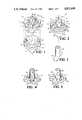
- FIG. 1is an exploded perspective view of a plunger according to one embodiment of the present invention.
- FIG. 2is a perspective view of a plunger, corresponding to the plunger construction shown in FIG. 1, as assembled.
- FIG. 3is a perspective view of a portion of a driving mechanism, such as may be employed with the plunger of the present invention.
- FIG. 4is a perspective view of the driving mechanism of a power injector, as engaged with the coupling means on the proximal face of a plunger according to one embodiment of the present invention.
- FIG. 5is a view of a portion of the driving mechanism of a power injector system, engaged with the coupling structure on the proximal face of a plunger according to one embodiment of the present invention, such view corresponding to that shown in FIG. 4, but with the head of the driving mechanism being rotated by 90° from the position shown in FIG. 4.
- FIG. 6is a side elevation view, in partial cross-section, of an angiographic syringe comprising a plunger according to one embodiment of the present invention, in operative engagement with power injector means.
- FIG. 7is a top plan view of the proximal surface of a plunger according to one embodiment of the present invention, shown with the associated portion of a power injector system, to illustrate the coaction therebetween.
- FIG. 8is a side elevation view, in partial section of an angiographic syringe according to one embodiment of the present invention, comprising a plunge in accordance with the present invention.
- FIG. 9is a partial perspective view of a power injector device featuring a rotatable carousel mounting two angiographic syringes in accordance with the present invention.
- FIG. 1a perspective view of a plunger 10 in accordance with one embodiment of the present invention.
- the plungeras illustrated comprises a plunger body 12 and a frontal sheath 14.
- the plunger body 12has a conical distal end portion 16 extending proximally to a distal cylindrical portion 18, rearwardly of which is provided a cylindrical proximal portion 20.
- the respective distal and proximal cylindrical portions 18 and 20 of the plunger bodyare in axial spaced relationship to one another. Between the respective cylindrical portions 18 and 20 is a groove 22, having an interior surface defined by the intermediate cylindrical portion 24 of the plunger body.
- the central axis of the plunger assembly as shown in FIG. 1is indicated by line L--L.
- the proximal cylindrical portion 20 of the plunger body 12features a proximal face 26 which preferably is generally planar as shown.
- a coupling structurecomprising power driving means (ram) retention members 30 and 32, which as shown are symmetrically disposed on the proximal surface 26, diametrally opposite and laterally spaced apart from one another, in symmetrical relationship to the central axis L--L of the plunger.
- power driving meansram
- the samecomprises a leg portion 34 extending generally rearwardly from the proximal face 26 and joined at a rearward part thereof to a bridge segment 36 which laterally inwardly extends from the rearward part of the leg portion 34 toward the other retention member 32, which is similarly constructed with leg portion 38 and bridge segment 40.
- the inner extremities of the respective bridge segments 36 and 40 of the laterally opposed retention membersare thus in spaced relationship to one another to accommodate transverse passage of the drive shaft of a driving mechanism therethrough.
- transversewill generally refer to the direction of engagement of the power driving means (ram) with the plunger, and the direction of disengagement therefrom. In FIG. 1 this direction is generally indicated by the transverse line A--A.
- the transverse dimensionthus is generally perpendicular to the central axis L--L of the plunger, as illustrated.
- lateralrefers to a direction which is generally perpendicular to the transverse direction as well as to the axis L--L, and is indicated in FIG. 1 by the lateral line B--B.
- leg portion 34 and bridge segment 36 of retention member 30defines with the proximal face 26 of the plunger a slot 42.
- the leg portion 38 and bridge segment 40 of retention member 32defines with the proximal face 26 a slot 44.
- slot segments 42 and 44which accommodates transverse passage of the driving head of the driving means therethrough.
- transversely outwardly extending flange elements 46 and 48At the inner lateral extremity of bridge segment 36 of retention member 30 is joined transversely outwardly extending flange elements 46 and 48.
- Retention member 32is similarly configured, with transversely outwardly extending flange elements 50 and 52 joined to the inner lateral extremity of bridge segment 40.
- the respective flange elements 46, 48, 50 and 52are formed of a flexible, resilient material accommodating lateral deformation of these flange elements, as hereinafter more fully described.
- the plunger construction shown in FIG. 1provides transversely aligned pairs of the laterally spaced-apart flange elements, viz., a first flange element pair comprising flange elements 46 and 50, and a second flange element pair comprising flange elements 48 and 52, on the respective sides of the bridge segments.
- the paired flange elementsbound and define a transverse channel 60 therebetween.
- the plunger body 12may be formed, if desired, with a central cavity therein (not shown), as described in the aforementioned prior copending U.S. patent application No. 07/299,974, to minimize weight and material requirements for the plunger, as well as to facilitate molding, by providing faster mold cycling times, when the plunger body is formed of a molded material.
- the distal sheath 14 of the plungeris adapted to fit matingly over the distal conical portion 16, and the respective distal and intermediate cylindrical portion 18 and 24, of the plunger body.
- the distal sheathpreferably is formed of a resilient material, of sufficient intrinsic lubricity or amenability to lubrication, to yield it slidingly engageable with the inner wall surface of a syringe in which the plunger is deployed.
- the distal sheath 14comprises distal conical portion 72 and a proximal portion 74 whose outer surface describes axially spaced-apart ridges 76 and 78 bounding a groove 80 therebetween.
- the sheath wallis of generally uniform thickness along the conical distal portion 72. At its rearward extremity the sheath wall forms a radially inwardly extending flange 82 which mates cooperatively with the groove 22 of the plunger body, when the sheath and body of the plunger are cooperatively mated with one another.
- the plunger body 12may be formed of any suitable material of construction which is advantageously employed in the use environments of the plunger and syringe with which the plunger may be associated.
- the plunger bodymay for example be formed of a generally stiff, resilient material, such as a hard elastomer, or alternatively, it may be formed of any other suitable natural or synthetic, polymeric or non-polymeric, materials. In practice, plastics generally are preferred materials of construction.
- a polymeric material which may be employed to good advantage in such plunger bodyis polyphenylene oxide, such as the polyphenylene oxide material commercially available from General Electric Company, Pittsfield, Mass., under the trademark Valox®.
- the plunger sheath 14likewise may be formed of any suitable material which is advantageously employed in the use environments of the plunger and syringes with which same is associated. Preferred materials of construction include rubber materials, with natural rubber typically being the most preferred.
- the sheathis suitably flexible, resilient, and elastomeric in character, to accommodate mating with the plunger body in a manner ensuring that the sheath is retained in position on the plunger body during the use of the plunger.
- the retention members 30 and 32may be formed of any suitable materials of construction, with the proviso that the flange elements 46, 48, 50, and 52 must be flexible and resilient in character, to accommodate deformation thereof during the engagement and disengagement of the drive means during the use of the plunger in a power-driven angiographic syringe system. Accordingly, the retention members 30 and 32 may be formed of the same material of construction as the plunger body 12, if such material provides the requisite structural integrity in the plunger body and leg portions and bridge segments of the coupling structure, while concomitantly providing sufficient flexibility and resilience in the flange elements 46, 48, 50, and 52.
- the retention members 30 and 32may be formed integrally with the plunger body 12, such as by injection molding, machining, or other suitable forming method(s).
- the retention members 30 and 32may be formed separately from the plunger body, and affixed thereto at the lower extremities of the respective leg portions 34 and 38 by any suitable means or methods efficacious for such securement, e.g., adhesive bonding, ultrasonic welding, fusion bonding, mechanical fastening, etc.
- the flange elementsmay be formed separately from the leg portions and bridge segments of the respective retention members, or any two of such elements may be formed separately from the third, and correspondingly joined in any suitable manner.
- the leg portions and bridge segments of the respective retention membersmay be integrally molded from a suitable plastic material with the plunger body and subsequent to such formation, flange elements 46, 48, 50, and 52 may be suitably attached to the inner lateral extremities of the corresponding bridge segments.
- FIG. 2A perspective view of a plunger, as assembled from the sheath and body components of FIG. 1, is shown in FIG. 2, wherein all parts and elements are numbered correspondingly with respect to the same or corresponding features in FIG. 1.
- FIG. 3is a perspective view of a portion of a driving mechanism including an axially extending shaft 88, joined at its lower extremity (in the position shown) to a driving head 90.
- the drive shaft 88 and driving head 90corporately are referred to herein as the "ram" of the power injector system.
- FIG. 4is a perspective view of a proximal surface portion of a plunger according to one embodiment of the present invention, with the coupling means on proximal face 26 engaged with the ram comprising shaft 88 and driving head 90.
- the coupling means on proximal face 26engaged with the ram comprising shaft 88 and driving head 90.
- all parts and featuresare numbered correspondingly with respect to FIGS. 1-3 herein.
- the shaft 88 of the ramis engaged in a central (medical) portion of the transverse channel 60 which is bounded by the respective flange elements 46, 48, 50, and 52. These flange elements are joined to the corresponding bridge respective retention members 30 and 32.
- retention member 30comprises a leg portion 34 joined to a laterally extending bridge segment 36, to the innermost lateral extremity of which are joined transversely outwardly extending flange elements 46 and 48, in the previously described manner.
- retention member 32comprises leg portion 38, which is joined at rearward part thereof to laterally extending bridge segment 40.
- Flange elements 50 and 52are joined at their respective transversely inner extremities to the lateral inner extremity of the bridge segment 40.
- FIG. 5is a corresponding view of the FIG. 4 engaged plunger assembly, wherein all parts and features are correspondingly numbered, but wherein the shaft 88 has been rotated by 90° relative to the position shown in FIG. 4.
- the retention members 30 and 32are dimensionally sized and shaped to accommodate free rotation of the driving head 90 incident to rotation of driving shaft 88, with the provision of a laterally extending slot comprising slot segments 42 and 44 between the proximal face 26 of he plunger and the respective leg portions and bridge segments of the retention members.
- FIG. 6is a top plan view of the proximal surface 26 of the plunger according to one embodiment of the present invention featuring a coupling structure mounted on the proximal face including retention members 30 and 32.
- the proximal face of the plunger and the coupling structure thereonare shown in associative relationship with a ram comprising driving shaft 88, to which is joined a driving head 90 in the manner shown and described with reference to FIG. 3 herein.
- the ram and plunger shown in FIG. 6are numbered correspondingly with respect to FIGS. 1-5 herein.
- the flange elements 46 and 48are joined at their inner transverse extremities to the bridge segment 36 of retaining member 30.
- flange elements 50 and 52are joined at their inner transverse extremities to bridge segment 40 of retaining member 32.
- the respective bridge segments 36 add 40may, as shown, be formed with laterally extending cavities 94 and 96, respectively, to enhance the flexible and resilient character of the flange elements attached thereto.
- the respective retention members 30 and 32may be configured with a flattened "wishbone" shape as shown in the plan view illustrated.
- the respective flange elements 46, 48, 50, and 52corporately bound and define a transversely extending channel 60 (the transverse center line A--A of such channel being shown for ease of reference).
- the transverse channel 60comprises a medial portion 100, and marginal portions 102 and 104.
- the overall flattened W-shape of the respective pairs of flange elements transversely bounding the channel 60(viz., flange elements 46 and 48 as a first pair, and flange elements 50 and 52 as a second pair) provides a channel configuration wherein the marginal channel portions 102 and 104 are of reduced channel width relative to the medial portion 100 of the channel.
- the marginal portion 104 of the passage 60defines a channel width at the point of closest proximity of the respective facing flange elements 48 and 52 which is denoted as dimension W in the FIG. 6 drawing.
- the normal width dimension W of such portion of the channelis indicated, with the respective facing flange elements 46 and 50 bounding such marginal portion of the channel being laterally displaced in the direction of arrows C and D, respectively, to indicate the deformation of these flange elements which occurs when the driving means comprising driving shaft 88 and driving head 90 is translated in the transverse direction indicated by arrow E for engagement with the retention members.
- the driving mechanismis engaged with the plunger 10 by translating the driving means comprising shaft 88 and head 90 in the direction of arrow E along transverse center line A--A, to cause same to pass successively through the marginal portion 102 of the transverse channel 60 to the medial portion 100 thereof, to finally repose in the position indicated in dotted line outline, on which the diameter of the driving shaft 88 is indicate as dimension D 1 .
- the driving mechanismcomprising shaft 88 and head 90 is reposed in the medial portion 100 of the transverse channel 60, it will be apparent that the driving mechanism thereafter is non-disengageable from the plunger by simple rotation of the driving head relative to the plunger. Accordingly, it is possible to disengage the driving mechanism from the plunger, once engaged therewith, only by transverse translation of the driving mechanism relative to the plunger, i.e., translation of the driving mechanism in a direction along transverse center line A--A. It will also be appreciated that the driving mechanism may be thus disengaged from the plunger in both transversely opposite directions. In other words, the driving mechanism, once reposed in the medial portion 10 of the transverse channel, can be disengaged from the plunger by either transverse translation through the marginal channel portion 102, or by transverse translation of the driving mechanism through marginal channel 104.
- the bi-directional character of the driving mechanism engagement and retention means in the plunger of the present inventionovercomes the difficulties associated with the directional character of the plunger disclosed in prior copending U.S. patent application No. 07/299,974 filed Jan. 19, 1989.
- FIG. 7is a side elevation view, in partial section, showing an angiograhic syringe comprising the plunger of the present invention, add an associated part of the driving mechanism of an angiography power injector system, in engagement with the plunger.
- the angiographic syringe 170comprises a generally cylindrical barrel 172, which terminates at its proximal end in a circumferentially continuous, radially extending flange 174.
- the plunger 110is reposed in the interior volume 175 of the angiographic syringe 170, with the ridges 146 and 148 of the plunger sheath being in contact with the inner wall surface 180 of the angiographic syringe.
- the plungercomprises a coupling structure 128 as previously described in FIGS. 1-6 hereof, with the retention members 130 and 132 corporate defining with the rear face 126 of the plunger a cavity 182.
- the cavity 182is constructed and arranged for transversely receiving the head 184 of the driving mechanism 186.
- Flange elements 190 and 192, together with corresponding flange elements on the opposite side of the plunger from that shown,corporately define a transversely extending channel into which the head 184 and shaft 188 of the driving mechanism are transversely inserted for engagement with the plunger, and from which the head and shift of the driving mechanism are transversely withdrawn for disengagement from the plunger, as previously described.
- the driving head 184thus is mounted on the axially extending drive shaft 188, and the driving mechanism comprises means (not shown) for axially extending or retracting the shaft 188 and head 184 as desired.
- FIG. 8is a side elevation view, in section, of an angiographic syringe according to one embodiment of the present invention, comprising a plunger of the type shown in FIGS. 1-7 hereof.
- the angiographic syringe 270comprises a generally cylindrical barrel 272 enclosing an interior volume 275 in which the plunger 210 is slidably mounted, in engagement, at ridges 246 and 248, with the inner wall surface 280 of the syringe barrel.
- the syringe barrelterminates at a proximal end in radially outwardly extending flange 274.
- the syringe barrel 272is joined via a frustoconical section 290 to distal tapered section 292, which in turn is joined at a distal extremity thereof to the tubular discharge section 294.
- the tapered section 292 of the syringeoptionally features, at a proximal portion thereof, a plurality of vanes 276, which may be employed for positive locking of the syringe in the mounting structure of a power injector system.
- the tapered section 292features o a distal portion of its exterior surface a threading 298, by means of which the angiographic syringe may be coupled, via a suitable complimentarily threaded connecting fitting, to an angiography catheter (not shown).
- FIG. 9is a perspective view of an angiography injection system 300 including power injector 302.
- the power injectorcomprises a carrousel 304 mounted for rotation, e.g., in the direction indicated by arrow S in FIG. 9, and contains openings bounded by collars 306 through which syringes 370a and 370b are inserted.
- the lower syringe 370bhas been placed, by selective adjustment of the carrousel, in engagement position with the driving mechanism of the power injector 302, so that the plunger 310b of syringe 370b is in engagement with the head and shaft of the driving mechanism.
- the angiographic syringe 370acomprising plunger 310a, is mounted in position on the upper segment of the carrousel, for subsequent translation into alignment with the power injector driving mechanism, and concurrent disengagement of the plunger 310b of syringe 370b therefrom.
- the plunger of the inventionmay have a body formed of Valox® polyphenylene oxide (General Electric Company, Pittsfield, Mass.) and a sheath of natural rubber.
- the conical distal portion 16 of the body(see FIG. 1) comprises surfaces which define with the central axis of L--L of he body an included angle of 45°.
- the diameter of the proximal cylindrical portion 20 of the plungeris 1.59 inch
- the diameter of the distal cylindrical portion 18 of the plungeris 1.405 inch
- the diameter of the intermediate cylindrical portion 24 of the plungeris 1.165 inch.
- the distal cylindrical portion 20 of the plunger in this illustrative embodimenthas an axial thickness of 0.125 inch
- the intermediate cylindrical portion 24 of the plungerhas an axial thickness of 0.18 inch
- the distal cylindrical portion 18 of the plungerhas an axial thickness of 0.12 inch.
- the axial distance from the proximal face 26 to the bridge segments 36 and 40 bounding respective slot segments 42 and 44is 0.165 inch.
- the axial height of the retention members 30 and 32, as measured axially from the rear face 26 of the plunger body,is 0.335 inch and the diameter of the lateral slot comprising slot segments 42 and 44, is 1.04 inch.
Landscapes
- Health & Medical Sciences (AREA)
- Vascular Medicine (AREA)
- Engineering & Computer Science (AREA)
- Anesthesiology (AREA)
- Biomedical Technology (AREA)
- Heart & Thoracic Surgery (AREA)
- Hematology (AREA)
- Life Sciences & Earth Sciences (AREA)
- Animal Behavior & Ethology (AREA)
- General Health & Medical Sciences (AREA)
- Public Health (AREA)
- Veterinary Medicine (AREA)
- Infusion, Injection, And Reservoir Apparatuses (AREA)
Abstract
Description
Claims (10)
Priority Applications (2)
| Application Number | Priority Date | Filing Date | Title |
|---|---|---|---|
| US07/332,709US4911695A (en) | 1989-04-03 | 1989-04-03 | Plunger for power-driven angiographic syringe, and syringe and power injector system utilizing same |
| PCT/US1990/001550WO1990011788A1 (en) | 1989-04-03 | 1990-03-22 | Plunger for power-driven angiographic syringe |
Applications Claiming Priority (1)
| Application Number | Priority Date | Filing Date | Title |
|---|---|---|---|
| US07/332,709US4911695A (en) | 1989-04-03 | 1989-04-03 | Plunger for power-driven angiographic syringe, and syringe and power injector system utilizing same |
Publications (1)
| Publication Number | Publication Date |
|---|---|
| US4911695Atrue US4911695A (en) | 1990-03-27 |
Family
ID=23299514
Family Applications (1)
| Application Number | Title | Priority Date | Filing Date |
|---|---|---|---|
| US07/332,709Expired - LifetimeUS4911695A (en) | 1989-04-03 | 1989-04-03 | Plunger for power-driven angiographic syringe, and syringe and power injector system utilizing same |
Country Status (2)
| Country | Link |
|---|---|
| US (1) | US4911695A (en) |
| WO (1) | WO1990011788A1 (en) |
Cited By (57)
| Publication number | Priority date | Publication date | Assignee | Title |
|---|---|---|---|---|
| US5078686A (en)* | 1988-06-28 | 1992-01-07 | Bates William T D | Single-use syringe |
| US5085638A (en)* | 1988-03-31 | 1992-02-04 | David Farbstein | Single use disposable syringe |
| US5314415A (en)* | 1993-07-21 | 1994-05-24 | Sterling Winthrop Inc. | Aspirating plunger for power injector cartridges |
| US5423757A (en)* | 1991-04-22 | 1995-06-13 | Olovson; Gudmar | Syringe, having a rod and a piston and a disconnect mechanism |
| US5459700A (en)* | 1993-11-22 | 1995-10-17 | Advanced Cardiovascular Systems, Inc. | Manual timer control for inflation device |
| US5460609A (en)* | 1993-11-22 | 1995-10-24 | Advanced Cardiovascular Systems, Inc. | Electromechanical inflation/deflation system |
| US5484414A (en)* | 1994-09-21 | 1996-01-16 | Pace; Paul A. | Syringe incorporating a self-contained retractable needle |
| US5531703A (en)* | 1992-04-28 | 1996-07-02 | Schering-Plough Healthcare Products, Inc. | Applicator for semisolid medications |
| US5562621A (en)* | 1993-11-22 | 1996-10-08 | Advanced Cardiovascular Systems, Inc. | Communication system for linking a medical device with a remote console |
| US5562614A (en)* | 1993-11-22 | 1996-10-08 | Advanced Cardiovascular Systems, Inc. | Programmable manifold system for automatic fluid delivery |
| US5599301A (en)* | 1993-11-22 | 1997-02-04 | Advanced Cardiovascular Systems, Inc. | Motor control system for an automatic catheter inflation system |
| WO1998020920A3 (en)* | 1996-11-12 | 1998-08-27 | Medrad Inc | Prefillable syringes, plungers and injectors for use therewith |
| US5873861A (en)* | 1996-11-12 | 1999-02-23 | Medrad, Inc. | Plunger systems |
| WO1999020327A3 (en)* | 1997-10-21 | 1999-07-01 | I Flow Corp | Spring-actuated infusion syringe |
| US5944694A (en)* | 1996-11-12 | 1999-08-31 | Medrad, Inc. | Prefillable syringes and injectors for use therewith |
| US5947935A (en)* | 1996-11-12 | 1999-09-07 | Medrad, Inc. | Syringes, syringe plungers and injector systems |
| US5947929A (en)* | 1997-08-22 | 1999-09-07 | Coeur Laboratories, Inc. | Front-load angiographic injector system, angiographic syringe and plunger for angiographic syringe |
| US6080136A (en)* | 1998-06-11 | 2000-06-27 | Polyten Plastics, Llc | Angiographic syringe adapter for front-loading injector |
| US6196999B1 (en) | 1999-02-05 | 2001-03-06 | Liebel-Flarsheim Company | Syringe/plunger coupling |
| US6402717B1 (en) | 1992-08-17 | 2002-06-11 | Medrad, Inc. | Front-loading medical injector and syringe for use therewith |
| US6402718B1 (en) | 1992-08-17 | 2002-06-11 | Medrad, Inc. | Front-loading medical injector and syringe for use therewith |
| US6432089B1 (en)* | 2000-06-21 | 2002-08-13 | Medrad, Inc. | Medical syringe |
| US20020165491A1 (en)* | 1999-11-24 | 2002-11-07 | Reilly David M. | Injectors, injector systems, syringes and methods of connecting a syringe to an injector |
| US20030040719A1 (en)* | 1996-03-29 | 2003-02-27 | Spohn Michael A. | Front-loading syringe adapter for front-loading medical injector |
| US6652489B2 (en) | 2000-02-07 | 2003-11-25 | Medrad, Inc. | Front-loading medical injector and syringes, syringe interfaces, syringe adapters and syringe plungers for use therewith |
| US20040064041A1 (en)* | 2002-05-30 | 2004-04-01 | Lazzaro Frank A. | Front-loading medical injector and syringes, syringe interfaces, syringe adapters and syringe plungers for use therewith |
| US20060151545A1 (en)* | 2003-07-03 | 2006-07-13 | Erich Imhof | Device for administering a liquid product |
| US20080082055A1 (en)* | 2006-09-29 | 2008-04-03 | Tyco Healthcare Group Lp | Detachable plunger rod syringe |
| US7419478B1 (en) | 2003-06-25 | 2008-09-02 | Medrad, Inc. | Front-loading syringe for medical injector having a flexible syringe retaining ring |
| WO2009036496A2 (en) | 2007-09-21 | 2009-03-26 | Imaxeon Pty Ltd | A releasable connecting mechanism |
| US20090216192A1 (en)* | 2002-12-20 | 2009-08-27 | Medrad, Inc. | Fluid injection apparatus having anti-rotation elements to limit syringe plunger rotation |
| US20090259183A1 (en)* | 2008-04-11 | 2009-10-15 | Medtronic Minimed, Inc. | Reservoir barrier layer systems and methods |
| WO2009126596A3 (en)* | 2008-04-11 | 2009-12-10 | Medtronic Minimed, Inc. | Reservoir plunger head systems and methods |
| US20100016791A1 (en)* | 2008-04-11 | 2010-01-21 | Medtronic Minimed, Inc. | Reservoir barrier layer systems and methods |
| US20100057014A1 (en)* | 2006-11-16 | 2010-03-04 | CANE' S.P.A. -Socio Unico | Syringe plunger and syringe incorporating the plunger |
| DE102008058037A1 (en)* | 2008-11-18 | 2010-05-20 | Imp Pape Gmbh & Co. Kg | Piston for syringe used in injection or infusion device to inject or withdraw medicinal fluid, has piston casing wall including threaded region with multiple recesses fixing planar connection elements, which are arranged on piston wall |
| US20100237094A1 (en)* | 2009-03-18 | 2010-09-23 | Benjamin Ii Wilken | Plunger apparatus for emptying a cartridge using paint stir stick |
| US20120109076A1 (en)* | 2009-07-17 | 2012-05-03 | Daikyo Seiko, Ltd. | Piston for syringe having very small capacity, and plunger having the piston mounted thereto |
| US8628495B2 (en) | 2009-08-13 | 2014-01-14 | Mallinckrodt Llc | Power injector syringe assembly |
| US20140350396A1 (en)* | 2005-04-27 | 2014-11-27 | C. R. Bard, Inc. | Assemblies for Identifying a Power Injectable Access Port |
| JP2015517858A (en)* | 2012-05-30 | 2015-06-25 | サノフィ−アベンティス・ドイチュラント・ゲゼルシャフト・ミット・ベシュレンクテル・ハフツング | Piston rod body support for drug delivery device, piston rod arrangement, and piston rod body |
| US9108047B2 (en) | 2010-06-04 | 2015-08-18 | Bayer Medical Care Inc. | System and method for planning and monitoring multi-dose radiopharmaceutical usage on radiopharmaceutical injectors |
| US9174003B2 (en) | 2012-09-28 | 2015-11-03 | Bayer Medical Care Inc. | Quick release plunger |
| US9480797B1 (en) | 2015-10-28 | 2016-11-01 | Bayer Healthcare Llc | System and method for syringe plunger engagement with an injector |
| US9694131B2 (en) | 2003-11-25 | 2017-07-04 | Bayer Healthcare Llc | Medical injector system |
| US9844622B2 (en) | 2000-07-10 | 2017-12-19 | Bayer Healthcare Llc | Syringes for medical injector systems |
| US9855390B2 (en) | 2006-03-15 | 2018-01-02 | Bayer Healthcare Llc | Plunger covers and plungers for use in syringes |
| USD847985S1 (en) | 2007-03-14 | 2019-05-07 | Bayer Healthcare Llc | Syringe plunger cover |
| US10806852B2 (en) | 2014-03-19 | 2020-10-20 | Bayer Healthcare Llc | System for syringe engagement to an injector |
| US20200330690A1 (en)* | 2018-05-15 | 2020-10-22 | Becton, Dickinson And Company | Syringe Plunger Stopper for High Dose Accuracy Drug Delivery |
| US11148168B2 (en)* | 2017-12-19 | 2021-10-19 | Wolfcraft Gmbh | Piston assembly for a cartridge discharging device |
| USD942005S1 (en) | 2007-03-14 | 2022-01-25 | Bayer Healthcare Llc | Orange syringe plunger cover |
| USD1002840S1 (en) | 2007-03-14 | 2023-10-24 | Bayer Healthcare Llc | Syringe plunger |
| US11883636B2 (en) | 2018-02-27 | 2024-01-30 | Bayer Healthcare Llc | Syringe plunger engagement mechanism |
| US11969582B2 (en) | 2017-01-06 | 2024-04-30 | Bayer Healthcare Llc | Syringe plunger with dynamic seal |
| US11998718B2 (en) | 2020-06-18 | 2024-06-04 | Bayer Healthcare Llc | System and method for syringe plunger engagement with an injector |
| USD1031029S1 (en) | 2003-11-25 | 2024-06-11 | Bayer Healthcare Llc | Syringe plunger |
Citations (10)
| Publication number | Priority date | Publication date | Assignee | Title |
|---|---|---|---|---|
| DE195026C (en)* | ||||
| FR416385A (en)* | 1910-05-25 | 1910-10-18 | Martial Louis Boyer | Reservoir syringe |
| US2524367A (en)* | 1948-03-08 | 1950-10-03 | Arthur E Smith | Hypodermic ampoule syringe |
| US2722215A (en)* | 1954-04-27 | 1955-11-01 | Dahlgren Stig-Ake | Spring-actuated medical syringe |
| US3057351A (en)* | 1959-11-16 | 1962-10-09 | Kimura Masahiko | Intravenous injection syringe |
| US3115135A (en)* | 1962-03-12 | 1963-12-24 | Stanley J Sarnoff | Aspirating piston and plunger coupling |
| DE2031841A1 (en)* | 1970-05-16 | 1972-06-08 | B.Braun Melsungen Ag, 3508 Melsungen | Disposable syringe - with multicompartment cylinder - for injections and blood sample collection |
| US4636198A (en)* | 1985-11-18 | 1987-01-13 | Mallinckrodt, Inc. | Power syringe with volume reducing adapter |
| US4677980A (en)* | 1984-06-06 | 1987-07-07 | Medrad, Inc. | Angiographic injector and angiographic syringe for use therewith |
| US4685910A (en)* | 1986-01-21 | 1987-08-11 | Abbott Laboratories | Apparatus and method for delivering secondary fluids to a patient using an intravenous administration set feeding a primary fluid |
- 1989
- 1989-04-03USUS07/332,709patent/US4911695A/ennot_activeExpired - Lifetime
- 1990
- 1990-03-22WOPCT/US1990/001550patent/WO1990011788A1/enunknown
Patent Citations (10)
| Publication number | Priority date | Publication date | Assignee | Title |
|---|---|---|---|---|
| DE195026C (en)* | ||||
| FR416385A (en)* | 1910-05-25 | 1910-10-18 | Martial Louis Boyer | Reservoir syringe |
| US2524367A (en)* | 1948-03-08 | 1950-10-03 | Arthur E Smith | Hypodermic ampoule syringe |
| US2722215A (en)* | 1954-04-27 | 1955-11-01 | Dahlgren Stig-Ake | Spring-actuated medical syringe |
| US3057351A (en)* | 1959-11-16 | 1962-10-09 | Kimura Masahiko | Intravenous injection syringe |
| US3115135A (en)* | 1962-03-12 | 1963-12-24 | Stanley J Sarnoff | Aspirating piston and plunger coupling |
| DE2031841A1 (en)* | 1970-05-16 | 1972-06-08 | B.Braun Melsungen Ag, 3508 Melsungen | Disposable syringe - with multicompartment cylinder - for injections and blood sample collection |
| US4677980A (en)* | 1984-06-06 | 1987-07-07 | Medrad, Inc. | Angiographic injector and angiographic syringe for use therewith |
| US4636198A (en)* | 1985-11-18 | 1987-01-13 | Mallinckrodt, Inc. | Power syringe with volume reducing adapter |
| US4685910A (en)* | 1986-01-21 | 1987-08-11 | Abbott Laboratories | Apparatus and method for delivering secondary fluids to a patient using an intravenous administration set feeding a primary fluid |
Cited By (125)
| Publication number | Priority date | Publication date | Assignee | Title |
|---|---|---|---|---|
| US5085638A (en)* | 1988-03-31 | 1992-02-04 | David Farbstein | Single use disposable syringe |
| US5078686A (en)* | 1988-06-28 | 1992-01-07 | Bates William T D | Single-use syringe |
| US5423757A (en)* | 1991-04-22 | 1995-06-13 | Olovson; Gudmar | Syringe, having a rod and a piston and a disconnect mechanism |
| US5531703A (en)* | 1992-04-28 | 1996-07-02 | Schering-Plough Healthcare Products, Inc. | Applicator for semisolid medications |
| US7081105B2 (en) | 1992-08-17 | 2006-07-25 | Medrad, Inc. | Injector system having a front loading pressure jacket assembly |
| US6402718B1 (en) | 1992-08-17 | 2002-06-11 | Medrad, Inc. | Front-loading medical injector and syringe for use therewith |
| US6808513B2 (en) | 1992-08-17 | 2004-10-26 | Medrad, Inc. | Front loading medical injector and syringe for use therewith |
| US6402717B1 (en) | 1992-08-17 | 2002-06-11 | Medrad, Inc. | Front-loading medical injector and syringe for use therewith |
| US6475192B1 (en) | 1992-08-17 | 2002-11-05 | Medrad, Inc. | System and method for providing information from a syringe to an injector |
| US6562008B1 (en)* | 1992-08-17 | 2003-05-13 | Medrad, Inc. | Front loading medical injector and syringe for use therewith |
| US6733478B2 (en) | 1992-08-17 | 2004-05-11 | Medrad, Inc. | System and method for providing information from a syringe to an injector |
| US20050059932A1 (en)* | 1992-08-17 | 2005-03-17 | Reilly David M. | Injector system having a front loading pressure jacket assembly |
| US5314415A (en)* | 1993-07-21 | 1994-05-24 | Sterling Winthrop Inc. | Aspirating plunger for power injector cartridges |
| US5460609A (en)* | 1993-11-22 | 1995-10-24 | Advanced Cardiovascular Systems, Inc. | Electromechanical inflation/deflation system |
| US5599301A (en)* | 1993-11-22 | 1997-02-04 | Advanced Cardiovascular Systems, Inc. | Motor control system for an automatic catheter inflation system |
| US5562614A (en)* | 1993-11-22 | 1996-10-08 | Advanced Cardiovascular Systems, Inc. | Programmable manifold system for automatic fluid delivery |
| US5562621A (en)* | 1993-11-22 | 1996-10-08 | Advanced Cardiovascular Systems, Inc. | Communication system for linking a medical device with a remote console |
| US5459700A (en)* | 1993-11-22 | 1995-10-17 | Advanced Cardiovascular Systems, Inc. | Manual timer control for inflation device |
| US5484414A (en)* | 1994-09-21 | 1996-01-16 | Pace; Paul A. | Syringe incorporating a self-contained retractable needle |
| US20060184157A1 (en)* | 1996-03-29 | 2006-08-17 | Spohn Michael A | Front-loading syringe adapter for front-loading medical injector |
| US7029458B2 (en)* | 1996-03-29 | 2006-04-18 | Medrad, Inc. | Front-loading syringe adapter for front-loading medical injector |
| US20030040719A1 (en)* | 1996-03-29 | 2003-02-27 | Spohn Michael A. | Front-loading syringe adapter for front-loading medical injector |
| US6322535B1 (en)* | 1996-11-12 | 2001-11-27 | Medrad, Inc. | Prefillable syringes and injectors for use therewith |
| US5947935A (en)* | 1996-11-12 | 1999-09-07 | Medrad, Inc. | Syringes, syringe plungers and injector systems |
| WO1998020920A3 (en)* | 1996-11-12 | 1998-08-27 | Medrad Inc | Prefillable syringes, plungers and injectors for use therewith |
| US6984222B1 (en)* | 1996-11-12 | 2006-01-10 | Medrad, Inc. | Plunger systems |
| US5873861A (en)* | 1996-11-12 | 1999-02-23 | Medrad, Inc. | Plunger systems |
| US6017330A (en)* | 1996-11-12 | 2000-01-25 | Medrad, Inc. | Plunger systems |
| US5944694A (en)* | 1996-11-12 | 1999-08-31 | Medrad, Inc. | Prefillable syringes and injectors for use therewith |
| US5947929A (en)* | 1997-08-22 | 1999-09-07 | Coeur Laboratories, Inc. | Front-load angiographic injector system, angiographic syringe and plunger for angiographic syringe |
| WO1999020327A3 (en)* | 1997-10-21 | 1999-07-01 | I Flow Corp | Spring-actuated infusion syringe |
| US6080136A (en)* | 1998-06-11 | 2000-06-27 | Polyten Plastics, Llc | Angiographic syringe adapter for front-loading injector |
| US8353879B2 (en) | 1999-02-05 | 2013-01-15 | Mallinckrodt Llc | Syringe/plunger coupling |
| US20080033358A1 (en)* | 1999-02-05 | 2008-02-07 | Liebel-Flarsheim Company | Syringe/Plunger Coupling |
| US7300417B1 (en) | 1999-02-05 | 2007-11-27 | Liebel-Flarsheim Company | Syringe/plunger coupling |
| US20130204129A1 (en)* | 1999-02-05 | 2013-08-08 | Liebel-Flarsheim Company Llc | Syringe/plunger coupling |
| US6196999B1 (en) | 1999-02-05 | 2001-03-06 | Liebel-Flarsheim Company | Syringe/plunger coupling |
| US7465290B2 (en) | 1999-11-24 | 2008-12-16 | Medrad, Inc. | Injector system including an injector drive member that automatically advances and engages a syringe plunger |
| US20040068223A1 (en)* | 1999-11-24 | 2004-04-08 | Reilly David M. | Injector system including an injector drive member that automatically advances and engages a syringe plunger |
| US6958053B1 (en) | 1999-11-24 | 2005-10-25 | Medrad, Inc. | Injector providing drive member advancement and engagement with syringe plunger, and method of connecting a syringe to an injector |
| US20020165491A1 (en)* | 1999-11-24 | 2002-11-07 | Reilly David M. | Injectors, injector systems, syringes and methods of connecting a syringe to an injector |
| US7029459B2 (en) | 1999-11-24 | 2006-04-18 | Medrad, Inc. | Injector system including a powered loading device for connecting a syringe to an injector |
| US20040133161A1 (en)* | 2000-02-07 | 2004-07-08 | Mark Trocki | Front-loading syringe adapted to releasably engage a medical injector regardless of the orientation of the syringe with respect to the injector |
| US7540856B2 (en) | 2000-02-07 | 2009-06-02 | Medrad, Inc. | Front-loading medical injector adapted to releasably engage a syringe regardless of the orientation of the syringe with respect to the injector |
| US20040133153A1 (en)* | 2000-02-07 | 2004-07-08 | Mark Trocki | Syringe adapter for use with a medical injector and method for adapting an injector |
| US20040133183A1 (en)* | 2000-02-07 | 2004-07-08 | Mark Trocki | Method of preparing for a fluid injection procedure using a medical injector and a syringe |
| US20040133162A1 (en)* | 2000-02-07 | 2004-07-08 | Mark Trocki | Front-loading medical injector adapted to releasably engage a syringe regardless of the orientation of the syringe with respect to the injector |
| US6652489B2 (en) | 2000-02-07 | 2003-11-25 | Medrad, Inc. | Front-loading medical injector and syringes, syringe interfaces, syringe adapters and syringe plungers for use therewith |
| US9636452B2 (en) | 2000-02-07 | 2017-05-02 | Bayer Healthcare Llc | Front-loading medical injector adapted to releasably engage a syringe regardless of the orientation of the syringe with respect to the injector |
| US8721596B2 (en) | 2000-02-07 | 2014-05-13 | Bayer Medical Care Inc. | Front-loading syringe adapted to releasably engage a medical injector regardless of the orientation of the syringe with respect to the injector |
| US6432089B1 (en)* | 2000-06-21 | 2002-08-13 | Medrad, Inc. | Medical syringe |
| US9844622B2 (en) | 2000-07-10 | 2017-12-19 | Bayer Healthcare Llc | Syringes for medical injector systems |
| US8574200B2 (en) | 2002-05-30 | 2013-11-05 | Medrad, Inc. | Dual syringe injector system |
| US20040064041A1 (en)* | 2002-05-30 | 2004-04-01 | Lazzaro Frank A. | Front-loading medical injector and syringes, syringe interfaces, syringe adapters and syringe plungers for use therewith |
| US8133203B2 (en) | 2002-05-30 | 2012-03-13 | Medrad, Inc. | Method of injecting fluids from a dual syringe injector system |
| US20090216192A1 (en)* | 2002-12-20 | 2009-08-27 | Medrad, Inc. | Fluid injection apparatus having anti-rotation elements to limit syringe plunger rotation |
| US8414540B2 (en)* | 2002-12-20 | 2013-04-09 | Ralph H. Schriver | Fluid injection apparatus having anti-rotation elements to limit syringe plunger rotation |
| US7419478B1 (en) | 2003-06-25 | 2008-09-02 | Medrad, Inc. | Front-loading syringe for medical injector having a flexible syringe retaining ring |
| US7798377B2 (en)* | 2003-07-03 | 2010-09-21 | Roche Diagnostics International Ag | Device for administering a liquid product |
| US20060151545A1 (en)* | 2003-07-03 | 2006-07-13 | Erich Imhof | Device for administering a liquid product |
| US9694131B2 (en) | 2003-11-25 | 2017-07-04 | Bayer Healthcare Llc | Medical injector system |
| EP3326673A1 (en)* | 2003-11-25 | 2018-05-30 | Bayer Healthcare LLC | Syringes, syringe interfaces and syringe plungers for use with medical injectors |
| US10434249B2 (en) | 2003-11-25 | 2019-10-08 | Bayer Healthcare Llc | Medical injector system |
| US10894124B2 (en) | 2003-11-25 | 2021-01-19 | Bayer Healthcare Llc | Medical injector system |
| US11596735B2 (en) | 2003-11-25 | 2023-03-07 | Bayer Healthcare Llc | Medical injector system |
| USD1031029S1 (en) | 2003-11-25 | 2024-06-11 | Bayer Healthcare Llc | Syringe plunger |
| US9937337B2 (en)* | 2005-04-27 | 2018-04-10 | C. R. Bard, Inc. | Assemblies for identifying a power injectable access port |
| US20140350396A1 (en)* | 2005-04-27 | 2014-11-27 | C. R. Bard, Inc. | Assemblies for Identifying a Power Injectable Access Port |
| US10668221B2 (en) | 2006-03-15 | 2020-06-02 | Bayer Healthcare Llc | Plunger covers and plungers for use in syringes |
| US9855390B2 (en) | 2006-03-15 | 2018-01-02 | Bayer Healthcare Llc | Plunger covers and plungers for use in syringes |
| US20080082055A1 (en)* | 2006-09-29 | 2008-04-03 | Tyco Healthcare Group Lp | Detachable plunger rod syringe |
| US8038656B2 (en)* | 2006-09-29 | 2011-10-18 | Tyco Healthcare Group Lp | Detachable plunger rod syringe |
| US8172814B2 (en)* | 2006-11-16 | 2012-05-08 | Cane' S.P.A. | Syringe plunger and syringe incorporating the plunger |
| US20100057014A1 (en)* | 2006-11-16 | 2010-03-04 | CANE' S.P.A. -Socio Unico | Syringe plunger and syringe incorporating the plunger |
| USD847985S1 (en) | 2007-03-14 | 2019-05-07 | Bayer Healthcare Llc | Syringe plunger cover |
| USD942005S1 (en) | 2007-03-14 | 2022-01-25 | Bayer Healthcare Llc | Orange syringe plunger cover |
| USD1002840S1 (en) | 2007-03-14 | 2023-10-24 | Bayer Healthcare Llc | Syringe plunger |
| USD1030052S1 (en) | 2007-03-14 | 2024-06-04 | Bayer Healthcare Llc | Syringe plunger |
| USD1030051S1 (en) | 2007-03-14 | 2024-06-04 | Bayer Healthcare Llc | Syringe plunger |
| WO2009036496A2 (en) | 2007-09-21 | 2009-03-26 | Imaxeon Pty Ltd | A releasable connecting mechanism |
| CN104353159B (en)* | 2007-09-21 | 2017-05-31 | 易麦克逊控股公司 | Releasable connecting mechanism |
| WO2009036496A3 (en)* | 2007-09-21 | 2009-05-14 | Imaxeon Pty Ltd | A releasable connecting mechanism |
| EP2200679A4 (en)* | 2007-09-21 | 2013-08-07 | Imaxeon Pty Ltd | REMOVABLE COUPLING MECHANISM |
| EP2808046A3 (en)* | 2007-09-21 | 2015-11-25 | Imaxeon Pty Ltd | A releasable connecting mechanism |
| US9295776B2 (en) | 2008-04-11 | 2016-03-29 | Medtronic Minimed, Inc. | Reservoir plunger head systems and methods |
| US8858501B2 (en) | 2008-04-11 | 2014-10-14 | Medtronic Minimed, Inc. | Reservoir barrier layer systems and methods |
| US8702655B2 (en) | 2008-04-11 | 2014-04-22 | Medtronic Minimed, Inc. | Reservoir barrier layer systems and methods |
| US8206353B2 (en) | 2008-04-11 | 2012-06-26 | Medtronic Minimed, Inc. | Reservoir barrier layer systems and methods |
| US20110192478A1 (en)* | 2008-04-11 | 2011-08-11 | Medtronic Minimed, Inc. | Reservoir barrier layer systems and methods |
| US20090326458A1 (en)* | 2008-04-11 | 2009-12-31 | Chong Colin A | Reservoir plunger head systems and methods |
| US9089637B2 (en) | 2008-04-11 | 2015-07-28 | Medtronic Minimed, Inc. | Reservoir plunger head systems and methods |
| US20090259183A1 (en)* | 2008-04-11 | 2009-10-15 | Medtronic Minimed, Inc. | Reservoir barrier layer systems and methods |
| US20100016791A1 (en)* | 2008-04-11 | 2010-01-21 | Medtronic Minimed, Inc. | Reservoir barrier layer systems and methods |
| WO2009126596A3 (en)* | 2008-04-11 | 2009-12-10 | Medtronic Minimed, Inc. | Reservoir plunger head systems and methods |
| DE102008058037B4 (en)* | 2008-11-18 | 2014-03-13 | Imp Pape Gmbh & Co. Kg | Piston and plunger set |
| DE102008058037A1 (en)* | 2008-11-18 | 2010-05-20 | Imp Pape Gmbh & Co. Kg | Piston for syringe used in injection or infusion device to inject or withdraw medicinal fluid, has piston casing wall including threaded region with multiple recesses fixing planar connection elements, which are arranged on piston wall |
| US20100237094A1 (en)* | 2009-03-18 | 2010-09-23 | Benjamin Ii Wilken | Plunger apparatus for emptying a cartridge using paint stir stick |
| US9561329B2 (en)* | 2009-07-17 | 2017-02-07 | Daikyo Seiko, Ltd. | Piston for syringe having very small capacity, and plunger having the piston mounted thereto |
| US20120109076A1 (en)* | 2009-07-17 | 2012-05-03 | Daikyo Seiko, Ltd. | Piston for syringe having very small capacity, and plunger having the piston mounted thereto |
| US8628495B2 (en) | 2009-08-13 | 2014-01-14 | Mallinckrodt Llc | Power injector syringe assembly |
| US9108047B2 (en) | 2010-06-04 | 2015-08-18 | Bayer Medical Care Inc. | System and method for planning and monitoring multi-dose radiopharmaceutical usage on radiopharmaceutical injectors |
| US9463335B2 (en) | 2010-06-04 | 2016-10-11 | Bayer Healthcare Llc | System and method for planning and monitoring multi-dose radiopharmaceutical usage on radiopharmaceutical injectors |
| US11612696B2 (en) | 2012-05-30 | 2023-03-28 | Sanofi-Aventis Deutschland Gmbh | Bearing for a piston rod body for a drug delivery device, a piston rod arrangement and a piston rod body |
| CN108815645A (en)* | 2012-05-30 | 2018-11-16 | 赛诺菲-安万特德国有限公司 | Bearing, piston rod assembly and the piston rod main body of piston rod main body for medicine delivery device |
| JP2015517858A (en)* | 2012-05-30 | 2015-06-25 | サノフィ−アベンティス・ドイチュラント・ゲゼルシャフト・ミット・ベシュレンクテル・ハフツング | Piston rod body support for drug delivery device, piston rod arrangement, and piston rod body |
| JP2018149335A (en)* | 2012-05-30 | 2018-09-27 | サノフィ−アベンティス・ドイチュラント・ゲゼルシャフト・ミット・ベシュレンクテル・ハフツング | Bearing for piston rod body for drug delivery device, piston rod arrangement, and piston rod body |
| US10286152B2 (en) | 2012-09-28 | 2019-05-14 | Bayer Healthcare Llc | Quick release plunger |
| US9174003B2 (en) | 2012-09-28 | 2015-11-03 | Bayer Medical Care Inc. | Quick release plunger |
| US9744305B2 (en) | 2012-09-28 | 2017-08-29 | Bayer Healthcare Llc | Quick release plunger |
| US10806852B2 (en) | 2014-03-19 | 2020-10-20 | Bayer Healthcare Llc | System for syringe engagement to an injector |
| US11103637B2 (en) | 2014-03-19 | 2021-08-31 | Bayer Healthcare Llc | System for syringe engagement to an injector |
| US11383029B2 (en) | 2014-03-19 | 2022-07-12 | Bayer Healthcare Llc | System for syringe engagement to an injector |
| US9480797B1 (en) | 2015-10-28 | 2016-11-01 | Bayer Healthcare Llc | System and method for syringe plunger engagement with an injector |
| US11547794B2 (en)* | 2015-10-28 | 2023-01-10 | Bayer Healthcare Llc | System and method for syringe plunger engagement with an injector |
| US10512721B2 (en) | 2015-10-28 | 2019-12-24 | Bayer Healthcare Llc | System and method for syringe plunger engagement with an injector |
| KR20230145515A (en)* | 2015-10-28 | 2023-10-17 | 바이엘 헬쓰케어 엘엘씨 | System and method for syringe plunger engagement with an injector |
| US12102793B2 (en) | 2015-10-28 | 2024-10-01 | Bayer Healthcare Llc | System and method for syringe plunger engagement with an injector |
| US11969582B2 (en) | 2017-01-06 | 2024-04-30 | Bayer Healthcare Llc | Syringe plunger with dynamic seal |
| US11148168B2 (en)* | 2017-12-19 | 2021-10-19 | Wolfcraft Gmbh | Piston assembly for a cartridge discharging device |
| US11883636B2 (en) | 2018-02-27 | 2024-01-30 | Bayer Healthcare Llc | Syringe plunger engagement mechanism |
| CN114904094A (en)* | 2018-05-15 | 2022-08-16 | 贝克顿·迪金森公司 | Syringe plunger stopper for high dose precision drug delivery |
| CN114904094B (en)* | 2018-05-15 | 2024-05-28 | 贝克顿·迪金森公司 | Syringe plunger stopper for high dose precision drug delivery |
| US12076536B2 (en)* | 2018-05-15 | 2024-09-03 | Becton, Dickinson And Company | Syringe plunger stopper for high dose accuracy drug delivery |
| US20200330690A1 (en)* | 2018-05-15 | 2020-10-22 | Becton, Dickinson And Company | Syringe Plunger Stopper for High Dose Accuracy Drug Delivery |
| US11998718B2 (en) | 2020-06-18 | 2024-06-04 | Bayer Healthcare Llc | System and method for syringe plunger engagement with an injector |
Also Published As
| Publication number | Publication date |
|---|---|
| WO1990011788A1 (en) | 1990-10-18 |
Similar Documents
| Publication | Publication Date | Title |
|---|---|---|
| US4911695A (en) | Plunger for power-driven angiographic syringe, and syringe and power injector system utilizing same | |
| US5007904A (en) | Plunger for power injector angiographic syringe, and syringe comprising same | |
| US5947929A (en) | Front-load angiographic injector system, angiographic syringe and plunger for angiographic syringe | |
| US6080136A (en) | Angiographic syringe adapter for front-loading injector | |
| US3316909A (en) | Hypodermic syringe operable by one hand | |
| US4929238A (en) | Multi-pressure injector device | |
| US4946442A (en) | Endoscope treatment device | |
| US6485470B2 (en) | Device for metered administration of an injectable product | |
| KR0145391B1 (en) | Simplified safety syringe with self-retracting needle and minimum size plunger | |
| US3388703A (en) | Intravenous cannula assembly unit | |
| WO1999010032A1 (en) | Angiographic injection syringe and front-load injector adapter | |
| CN1294524A (en) | needle retractable syringe | |
| MX2010013589A (en) | Fluid flow control device with retractable cannula. | |
| US6554796B2 (en) | Safty hypodermic syringe and needle holder for same | |
| WO1989012475A1 (en) | Syringe with retractable needle | |
| IL110926A0 (en) | Cartridge-needle unit having retractable needle | |
| MXPA04003994A (en) | Controlled release structure for attaching medical devices. | |
| EP4082491B1 (en) | Implant delivery system | |
| CN211674738U (en) | Implant delivery system | |
| US11350945B2 (en) | Staged deflation syringe systems and associated methods | |
| US4878899A (en) | Disposable syringe for one-time use | |
| KR101707181B1 (en) | Safety catheter assembly | |
| US5538507A (en) | Hypodermic syringe | |
| US11497861B2 (en) | Medical injection device | |
| CN211023326U (en) | Quick release's vascular stent delivery system |
Legal Events
| Date | Code | Title | Description |
|---|---|---|---|
| AS | Assignment | Owner name:COEUR LABORATORIES, INC., 2101 HARROD ST., RALEIGH Free format text:ASSIGNMENT OF ASSIGNORS INTEREST.;ASSIGNOR:LINDNER, THOMAS A.;REEL/FRAME:005059/0629 Effective date:19890322 | |
| STCF | Information on status: patent grant | Free format text:PATENTED CASE | |
| CC | Certificate of correction | ||
| AS | Assignment | Owner name:BRANCH BANKING & TRUST CO. Free format text:SECURITY INTEREST;ASSIGNOR:COEUR LABORATORIES, INC.;REEL/FRAME:005828/0275 Effective date:19910715 | |
| FPAY | Fee payment | Year of fee payment:4 | |
| FPAY | Fee payment | Year of fee payment:8 | |
| AS | Assignment | Owner name:COEUR ACQUISITIONS, L.L.C., NORTH CAROLINA Free format text:ASSIGNMENT OF ASSIGNORS INTEREST;ASSIGNOR:COEUR LABORATORIES, INC.;REEL/FRAME:010061/0340 Effective date:19990615 | |
| AS | Assignment | Owner name:POLYTEN PLASTICS, L.L.C., NORTH CAROLINA Free format text:MERGER;ASSIGNOR:COEUR ACQUISITION, L.L.C.;REEL/FRAME:010742/0333 Effective date:20000229 | |
| FPAY | Fee payment | Year of fee payment:12 | |
| FEPP | Fee payment procedure | Free format text:PAYOR NUMBER ASSIGNED (ORIGINAL EVENT CODE: ASPN); ENTITY STATUS OF PATENT OWNER: SMALL ENTITY | |
| AS | Assignment | Owner name:POLYTEN LLC, NORTH CAROLINA Free format text:CHANGE OF NAME;ASSIGNOR:POLYTEN PLASTICS, LLC;REEL/FRAME:013484/0866 Effective date:20000630 | |
| AS | Assignment | Owner name:COEUR LABORATORIES, INC., NORTH CAROLINA Free format text:RELEASE OF SECURITY INTEREST RECORDED AT REEL 5828;ASSIGNOR:BRANCH BANKING & TRUST CO.;REEL/FRAME:013496/0049 Effective date:19990615 | |
| AS | Assignment | Owner name:MASSACHUSETTS MUTAL LIFE INSURANCE COMPANY, MASSAC Free format text:SECURITY INTEREST;ASSIGNOR:COEUR, INC.;REEL/FRAME:014154/0384 Effective date:20030430 | |
| AS | Assignment | Owner name:COEUR, INC., NORTH CAROLINA Free format text:MERGER;ASSIGNOR:POLYTEN, LLC;REEL/FRAME:014066/0037 Effective date:20030430 | |
| AS | Assignment | Owner name:U.S. BANK NATIONAL ASSOCIATION, MINNESOTA Free format text:ASSIGNMENT OF ASSIGNORS INTEREST;ASSIGNOR:COEUR, INC.;REEL/FRAME:021754/0011 Effective date:20081010 Owner name:U.S. BANK NATIONAL ASSOCIATION,MINNESOTA Free format text:ASSIGNMENT OF ASSIGNORS INTEREST;ASSIGNOR:COEUR, INC.;REEL/FRAME:021754/0011 Effective date:20081010 | |
| AS | Assignment | Owner name:U.S. BANK NATIONAL ASSOCIATION, AS AGENT, MINNESOT Free format text:CORRECTIVE ASSIGNMENT TO CORRECT THE ASSIGNEE'S NAME AND THE NATURE OF CONVEYANCE PREVIOUSLY RECORDED ON REEL 021754 FRAME 0011;ASSIGNOR:COEUR, INC.;REEL/FRAME:022202/0164 Effective date:20081010 Owner name:U.S. BANK NATIONAL ASSOCIATION, AS AGENT,MINNESOTA Free format text:CORRECTIVE ASSIGNMENT TO CORRECT THE ASSIGNEE'S NAME AND THE NATURE OF CONVEYANCE PREVIOUSLY RECORDED ON REEL 021754 FRAME 0011. ASSIGNOR(S) HEREBY CONFIRMS THE ASSIGNMENT OF THE SECURITY INTEREST;ASSIGNOR:COEUR, INC.;REEL/FRAME:022202/0164 Effective date:20081010 Owner name:U.S. BANK NATIONAL ASSOCIATION, AS AGENT, MINNESOT Free format text:CORRECTIVE ASSIGNMENT TO CORRECT THE ASSIGNEE'S NAME AND THE NATURE OF CONVEYANCE PREVIOUSLY RECORDED ON REEL 021754 FRAME 0011. ASSIGNOR(S) HEREBY CONFIRMS THE ASSIGNMENT OF THE SECURITY INTEREST;ASSIGNOR:COEUR, INC.;REEL/FRAME:022202/0164 Effective date:20081010 | |
| AS | Assignment | Owner name:COEUR, INC., TENNESSEE Free format text:TERMINATION AND RELEASE OF SECURITY INTEREST IN PATENTS;ASSIGNOR:U.S. BANK NATIONAL ASSOCIATION;REEL/FRAME:029065/0721 Effective date:20120928 |