US4911525A - Optical communication cable - Google Patents
Optical communication cableDownload PDFInfo
- Publication number
- US4911525A US4911525AUS07/253,711US25371188AUS4911525AUS 4911525 AUS4911525 AUS 4911525AUS 25371188 AUS25371188 AUS 25371188AUS 4911525 AUS4911525 AUS 4911525A
- Authority
- US
- United States
- Prior art keywords
- flexible strip
- optical fiber
- optical
- optical cable
- adhesive
- Prior art date
- Legal status (The legal status is an assumption and is not a legal conclusion. Google has not performed a legal analysis and makes no representation as to the accuracy of the status listed.)
- Expired - Fee Related
Links
- 230000003287optical effectEffects0.000titleclaimsabstractdescription115
- 238000004891communicationMethods0.000titleabstractdescription4
- 239000013307optical fiberSubstances0.000claimsabstractdescription93
- 239000000853adhesiveSubstances0.000claimsabstractdescription54
- 230000001070adhesive effectEffects0.000claimsabstractdescription54
- 230000001681protective effectEffects0.000claimsabstractdescription38
- 238000009434installationMethods0.000claimsdescription13
- 239000000463materialSubstances0.000claimsdescription5
- 230000008878couplingEffects0.000claimsdescription4
- 238000010168coupling processMethods0.000claimsdescription4
- 238000005859coupling reactionMethods0.000claimsdescription4
- 238000000034methodMethods0.000claimsdescription4
- 238000005192partitionMethods0.000abstractdescription4
- 239000000835fiberSubstances0.000description19
- 239000010410layerSubstances0.000description10
- 238000010586diagramMethods0.000description4
- 238000005452bendingMethods0.000description2
- 230000007423decreaseEffects0.000description2
- 239000003365glass fiberSubstances0.000description2
- 230000007246mechanismEffects0.000description2
- 229920000728polyesterPolymers0.000description2
- 229920000642polymerPolymers0.000description2
- 229920000298CellophanePolymers0.000description1
- 230000009471actionEffects0.000description1
- 239000012790adhesive layerSubstances0.000description1
- WYTGDNHDOZPMIW-RCBQFDQVSA-NalstonineNatural productsC1=CC2=C3C=CC=CC3=NC2=C2N1C[C@H]1[C@H](C)OC=C(C(=O)OC)[C@H]1C2WYTGDNHDOZPMIW-RCBQFDQVSA-N0.000description1
- 230000000712assemblyEffects0.000description1
- 238000000429assemblyMethods0.000description1
- 239000003086colorantSubstances0.000description1
- 239000002131composite materialSubstances0.000description1
- 238000010276constructionMethods0.000description1
- 229920006333epoxy cementPolymers0.000description1
- 231100001261hazardousToxicity0.000description1
- 238000012986modificationMethods0.000description1
- 230000004048modificationEffects0.000description1
- 229920000915polyvinyl chloridePolymers0.000description1
- 239000004800polyvinyl chlorideSubstances0.000description1
- -1protective strandsSubstances0.000description1
- 229920005989resinPolymers0.000description1
- 239000011347resinSubstances0.000description1
- 239000002344surface layerSubstances0.000description1
- 239000013306transparent fiberSubstances0.000description1
Images


Classifications
- G—PHYSICS
- G02—OPTICS
- G02B—OPTICAL ELEMENTS, SYSTEMS OR APPARATUS
- G02B6/00—Light guides; Structural details of arrangements comprising light guides and other optical elements, e.g. couplings
- G02B6/44—Mechanical structures for providing tensile strength and external protection for fibres, e.g. optical transmission cables
- G02B6/4401—Optical cables
- G02B6/4403—Optical cables with ribbon structure
- G—PHYSICS
- G02—OPTICS
- G02B—OPTICAL ELEMENTS, SYSTEMS OR APPARATUS
- G02B6/00—Light guides; Structural details of arrangements comprising light guides and other optical elements, e.g. couplings
- G02B6/24—Coupling light guides
- G02B6/26—Optical coupling means
- G02B6/32—Optical coupling means having lens focusing means positioned between opposed fibre ends
- G—PHYSICS
- G02—OPTICS
- G02B—OPTICAL ELEMENTS, SYSTEMS OR APPARATUS
- G02B6/00—Light guides; Structural details of arrangements comprising light guides and other optical elements, e.g. couplings
- G02B6/44—Mechanical structures for providing tensile strength and external protection for fibres, e.g. optical transmission cables
- G02B6/4439—Auxiliary devices
- G02B6/4471—Terminating devices ; Cable clamps
Definitions
- This inventionrelates to fiber optic communication cables and, more particularly, to surface-mounted fiber optic cables intended primarily for indoor use.
- Fiber optic communication cableshave gained widespread use in long distance applications because of their wide bandwidth, small size and insensitivity to electrical interference.
- the optical fiber cablesWhen the optical fiber cables are run long distances, they are installed in a manner similar to electrical cables in protective jackets or conduits, usually on utility poles or underground.
- protective jackets or conduitsWhen optical fiber cables are installed in buildings, they are usually encased in protective jackets and are routed through conduits and cable trays using the same techniques that are employed for electrical cables. Such installation procedures are utilized despite the fact that optical fibers are extremely small in diameter and do not carry hazardous electrical potentials.
- optical fiber cablesin local area networks for telecommunications, computer network interconnection and the like is increasing. It is desirable to provide an optical fiber cable that is easy to install in buildings and is low in cost. These factors are particularly important when optical cable is being installed after completion of the building. In the past it has been customary to install optical cables in walls and between floors at high expense.
- a flat fiber optic cableis disclosed in U.S. Pat. No. 4,496,215 (Shaheen et al). Fiber optic filaments are embedded in a resin layer between first and second surface layers.
- the disclosed fiber optic cableis intended primarily for coupling signal paths between modules and subassemblies within electronic assemblies.
- an optical cablecomprising an elongated flexible strip, at least one optical fiber affixed to the flexible strip and an adhesive on a surface of the flexible strip.
- the optical cableis utilized for interconnecting points within a building by applying the adhesive to an interior wall, ceiling, floor or partition of the building.
- the optical cableis installed on a wall just below the intersection with the ceiling so that damage is unlikely and the cable is relatively unobtrusive.
- the flexible stripis a substantially transparent tape having a low specular reflection.
- the optical fiberis on the order of 30-60 micrometers in diameter. As a result, the optical cable is practically invisible when it is installed on a wall or other surface.
- the optical cablecan include at least one protective strand of glass fiber, wire, polymer filament or the like affixed to the flexible strip parallel to the optical fiber.
- a pair of protective strandsis embedded in the flexible strip on opposite sides of, and parallel to, the optical fiber.
- Each protective strandhas a diameter that is slightly larger than the optical fiber.
- the optical fiber and the protective strandsare sealed between two flexible strips, and the adhesive is applied to one of the outside surfaces.
- a removable filmpreferably covers the adhesive until the time of installation so that the optical cable can be rolled for storage and handling.
- An optical interconnection system in accordance with the inventionincludes an interconnection means attached to opposite ends of each optical fiber for coupling the optical cable to transmitting and/or receiving equipment or to another optical cable.
- the interconnection meanscan comprise a graded index lens coupled to the optical fiber.
- a connector blocksupports and aligns the graded index lens of each optical cable.
- the interconnection systemcan further include curvature-limiting devices for limiting the radius of curvature of the optical fiber at corners or at right angle bends in the plane of the cable.
- a method for interconnecting a first location and a second location within a building with an optical fibercomprising the steps of providing an optical cable including an elongated flexible strip, at least one optical fiber affixed to the flexible strip and an adhesive on a surface of the flexible strip, and attaching the optical cable to one or more walls of the building between the first location and the second location by applying the adhesive of the flexible strip to one or more of the walls.
- a tollfor applying the optical cable to a surface.
- the toolstores a complete optical cable having a removable film on a reel.
- one or more optical fibers, a flexible strip and adhesiveare applied to the surface to form an optical cable in place.
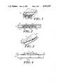
- FIG. 1is an enlarged, cross sectional view of an optical cable in accordance with the present invention
- FIG. 2is an enlarged, cross-sectional view of another embodiment of an optical cable in accordance with the present invention.
- FIG. 3illustrates a graded index lens attached to one end of the optical cable
- FIG. 4is an enlarged, elevation view of an arrangement for interconnecting two optical cables
- FIG. 5is an enlarged, cross-sectional view of the interconnection arrangement taken through the line 5--5 of FIG. 4;
- FIG. 6is an elevation view of a connector for interconnecting optical cables having multiple optical fibers
- FIG. 7is a schematic diagram illustrating the use of curvature-limiting devices at corners
- FIG. 8is an enlarged, cross-sectional view of a preferred optical cable in accordance with the present invention.
- FIG. 9is a perspective view of a cable section used for passing through walls
- FIG. 10illustrates a fixture for accommodating a right angle bend in the plane of the optical cable
- FIG. 11is a schematic diagram of a tool for installing a composite optical cable having a removable film.
- FIG. 12is a schematic diagram of a tool for installing separate optical fibers, protective strands, adhesive, and protective tape.
- FIG. 1An optical cable 8 in accordance with one embodiment of the invention is shown in FIG. 1.
- An enlarged cross-sectional view of the optical cable 8is shown.
- An elongated flexible strip 10has an adhesive 12 on one surface.
- One or more optical fibers 14are affixed to the flexible strip 10 on the same side as adhesive 12. In the embodiment of FIG. 1, the optical fibers 14 are held in place by the adhesive 12.
- the optical fibers 14are parallel to each other and run lengthwise along flexible strip 10.
- the flexible strip 10is preferably a transparent tape having low specular reflection.
- the flexible strip 10can be made in various colors and designs to match existing wall coverings.
- a preferred material for flexible strip 10is polyester. Any suitable long-life adhesive, such as a rubber based adhesive, can be utilized.
- the optical fibers 14preferably have a diameter in the range from about 30 to 60 micrometers.
- the optical cable 8 shown in FIG. 1is installed by applying he flexible adhesive strip to interior walls between the locations to be interconnected. Since the strip 10 is transparent and optical fibers 14 are extremely small in diameter, the optical cable is practically invisible when it is installed on a wall. Preferably, the cable 8 is installed on the wall just below the intersection with the ceiling to prevent damage by children, furniture, etc. The cable 8 can also be installed on ceilings, floors, partitions and other interior surfaces, as necessary.
- FIG. 2An optical cable in accordance with another embodiment of the invention is illustrated in FIG. 2.
- Optical fibers 14are affixed to flexible strip 10 by adhesive 12, and protective strands 20 are located on opposite sides of each optical fiber 14.
- the protective strands 20run parallel to fibers 14, are flexible and are mechanically more durable than optical fibers 14.
- the protective strands 20are larger in diameter than optical fibers 14.
- Protective strands 20can be glass fibers, wires, polymer filaments or the like.
- An impact on the optical cablewill, in most cases, be absorbed by the protective strands 20 so that damage to the optical fiber 14 is avoided. It will be understood that any number of optical fibers 14 and protective strands 20 can be utilized in the optical cable.
- a temporary, easily removable film 24, such as cellophanepreferably covers adhesive 12 until the optical cable is ready for installation. The film 24 permits the optical cable to be rolled for storage and handling prior to installation.
- the optical cable of the present inventioncan be utilized in an optical interconnection system in which it is interconnected to other optical cables or to optical receiving and/or transmitting equipment by means of conventional optical fiber connectors.
- a preferred interconnection arrangementis illustrated in FIGS. 3-5.
- a graded index lens 30is attached to the end of optical fiber 14 so that its optical axis is aligned with optical fiber 14.
- a bonding material 32such as epoxy cement, is used to secure the optical fiber 14 to the graded index lens 30.
- the bonding material 32can also be applied to flexible strip 10 in the region of the interconnection for mechanical strength.
- a suitable graded index lens 00is a type known as Sel-Foc.
- FIGS. 4 and 5An arrangement for interconnecting two optical cables is illustrated in FIGS. 4 and 5.
- An alignment block, or connector block 40is provided with a V-shaped groove 42 in its top surface.
- An optical cable 44is terminated in a graded index lens 46
- an optical cable 48is terminated in a graded index lens 50, as shown in FIG. 3 and described above.
- the lenses 46 and 50are placed in the V-groove 42 with their ends abutting each other.
- a hold-down clamp 52which can be spring-loaded, secures lenses 46 and 50 in position on connector block 40.
- the hold down clamp 52can have any configuration suitable for holding the lenses 46 and 50 in fixed positions relative to each other.
- the V-groove 42insures alignment between the optical axes of lenses 46 and 50.
- the connector block 40can be provided with an adhesive 54 for convenient installation.
- the optical scales of the present inventioncan be provided in a variety of different lengths with graded index lenses installed at each end.
- FIG. 6A connector suitable for interconnection of optical cables having multiple optical fibers is illustrated in FIG. 6.
- An optical cable 54having multiple optical fibers 56 and multiple protective strands 58 mounted on a tape 60, is terminated in a connector 62.
- the connector 62includes a lens fixture 64 having V-grooves for mounting of lenses 65 in parallel alignment.
- the fibers 56are coupled to the lenses 65, as described above, and the protective fibers 58 are cut back.
- FIG. 7A further feature of the optical interconnection system is illustrated n FIG. 7. It is known that optical fibers are subject to microbending losses and possible breakage at sharp bends or corners. To avoid such losses and to prevent breakage, curvature-limiting devices can be utilized at points where the cable is routed around a corner. As shown in FIG. 7, an inside curvature limiting device 66 is utilized for inside corners, and an outside curvature-limiting device 67 is used for outside corners.
- the curvature limiting devices 66 and 67can have any convenient construction, but most conveniently are molded.
- the inside surface 66a, 67a of each curvature limiting device 66, 67 that contacts the corneris formed as a right angle and preferably includes an adhesive for installation to the corner.
- the outside surface 66b, 67bis formed with a curvature having a radius of 1 centimeter or greater.
- a flexible strip 70includes a first flexible layer 72 and a second flexible layer 74. At least one optical fiber 76 is sealed between layers 72 and 74. Optional protective strands 78 can also be sealed between layers 72 and 74.
- An adhesive layer 80is applied to one surface of flexible strip 70. In this embodiment, the adhesive 80 is not used for affixing the optical fiber 76 to the flexible strip 70.
- a temporary, easily removable film 82covers adhesive 80 until the optical cable is ready for installation.
- the layers 72 and 74are preferably polyester.
- the optical fiber 76 and protective strands 78are heated and drawn between the layers 72 and 74. When the layers 72 and 74 ar brought into contact, the heated optical fiber 76 and strands 78 cause the layers 72, 74 to be heated and deformed so that an effective seal is formed between the layers 72 and 74.
- the optical cable described aboveis intended primarily for installation on wall surfaces. However, it is frequently necessary for the optical cable to pass through walls. In this case, the optical cable described above is not suitable.
- a cable section suitable for interconnection through wallsis shown in FIG. 9.
- a length of optical fiber 90is installed in a protective outer jacket 92 such as polyvinylchloride. Preferably, the outer jacket 92 is flexible to permit bending.
- the optical fiber 90is terminated at each end in a graded index lens 94 which extends beyond the end of jacket 92.
- the lenses 94are connected to the ends of optical cables constructed as described hereinabove to complete interconnection between points in the building.
- the assembly shown in FIG. 9can be constructed in various lengths for various applications.
- FIG. 10Another component of the optical interconnection system is shown in FIG. 10.
- the optical cable of the present inventionit is necessary for the optical cable of the present invention to be installed with a right angle bend in the plane of the cable.
- a cable that is more or less flatcannot make a right angle bend in its plane without lifting of the cable from the surface, since the inside of the bend is shorter than the outside of the bend.
- a right angle fixture 102is shown in FIG. 10. At the region of a right angle bend, the optical fibers in the cable are separated from the tape and installed in grooves in fixture 102.
- a first groove 104accommodates he fiber at the outside of the right angle bend, and a groove 106 accommodates the fiber at the inside of the bend.
- Additional groovescan be provided when additional fibers are present in the cable, and grooves can be provided for protective strands.
- the outside groove 104follows a gently curving 90° bend.
- Groove 106follows a serpentine, gently curving path that is equal in length to groove 104.
- the optical fibers in the cablecan all lay flat against the wall around a right angle bend.
- an optical cable in accordance with the present inventionmay be necessary for split into two or more similar optical cables.
- a beam splitter utilizing a 50% reflective mirror oriented at 45° with respect to the optical fiberscan be utilized for splitting optical signals from one cable to two cables.
- FIG. 11A schematic diagram of a manually-operable applicator tool for installing optical cables wherein the adhesive is protected by a removable film is shown in FIG. 11.
- a reel 120is rotatably mounted to a frame 122 having a handle 124.
- the optical cable to be installed, with the adhesive covered by a removable film,is rolled onto the reel 120.
- a drive wheel 126 and an idler wheel 128are rotatably mounted to a first leg 122a of frame 122.
- the drive wheel 126, the idler wheel 128 and the reel 120are in frictional contact at their edges and rotate together.
- a pressure roller 130is rotatably mounted to a second leg 122b of frame 122.
- a stripper 132 coupled to the first leg 122astrips the removable film from the optical cable as the cable is unrolled from reel 120.
- the optical cableis rolled onto reel 120, and the applicator tool is brought into contact with the wall or other surface on which the cable is to be installed.
- the drive wheel 126is caused by friction with the surface to rotate as the tool is moved.
- the optical fiberis delivered to the surface without stress or strain.
- the outside diameter of reel 120decreases.
- a spring 134maintains constant pressure between reel 120 and idler wheel 128 as the diameter of reel 120 decreases.
- the pressure roller 130is provided with a deformable surface, such as rubber, and forces the optical cable including the tape, optical fibers, protective strands and adhesive against the surface to insure a secure bond.
- a spring 136maintains a constant force between the pressure roller 130 and the surface as the applicator tool is moved.
- the stripper 132strips away the removable film as the optical cable is unrolled.
- optical cableIn cases where an optical cable must be installed behind an obstruction or through a hole that is not large enough to accommodate passage of the applicator, the optical cable is unwound from the reel 120, and the free end is threaded through the obstruction or hole and then remounted on the reel 120 so that installation may continue.
- FIG. 12An applicator tool suitable for installation of optical fibers that have not previously been affixed to a flexible strip by an adhesive is shown in schematic forming FIG. 12.
- a reel 220is rotatably mounted to a frame 222 having a handle 224.
- a drive wheel 226 and an idler wheel 228are rotatably mounted to a first leg 222a of frame 222.
- the drive wheel 226, the idler wheel 228 and the reel 220are in frictional contact at their edges and rotate together.
- a pressure roller 230is rotatably mounted to a second leg 222b of frame 222.
- each optical fiber and each protective strand of the optical cableare mounted on separate reels or on separate sections of one reel 220.
- the optical fibers and the protective strandsare aligned and spaced as they are removed from the reel 220 by a positioning mechanism 234 attached to frame 222.
- the adhesive dispenser 236is positioned adjacent to the pressure roller 230 so as to dispense adhesive over the optical fibers and protective strands that have been rolled onto the surface.
- a reel 240 and a pressure roller 242are rotatably mounted to a third leg 222c of frame 222.
- the flexible strip or tape for the optical cableis rolled onto reel 240.
- the reel 240 and pressure roller 242are positioned adjacent to adhesive dispenser 236 so as to unroll the tape over the optical fibers, protective strands and adhesive that have been applied to the surface.
- the pressures between each of the rollers 230 and 242 and the surface on which the cable is being installedare controlled by springs 244 and 246, respectively.
- the reel 220is maintained in contact with idler wheel 228 by a spring 248.
- the reel 220, the adhesive dispenser 236 and the reel 240define first, second and third stages, respectively, of the applicator tool.
- the optical fibers and protective strandsare unwound from the reel 220 in the first stage by the action of drive wheel 226 and idler wheel 228.
- the optical fibers and protective strandsare aligned and positioned by the positioning mechanism 234, and the pressure roller 230, having a deformable surface such as rubber, holds the fibers and protective strands in position on the surface.
- adhesiveis applied to the optical fibers, the protective strands and the surface by the adhesive dispenser 236 in the second stage.
- the width of the adhesive stripeis the same or slightly less than the width of the protective tape.
- the protective tapeis unrolled and is positioned over the adhesive.
- the pressure roller 242also having a deformable surface, forces the protective tape against the underlying materials and causes the adhesive to flow around and underneath the optical fibers and the protective strands.
- the optical cable disclosed hereinis low in cost and is extremely simple to install. When a transparent flexible strip is used, the installed cable is essentially invisible.
- the optical cablecan be placed at a location high on a wall to minimize the possibility of damage.
Landscapes
- Physics & Mathematics (AREA)
- General Physics & Mathematics (AREA)
- Optics & Photonics (AREA)
- Light Guides In General And Applications Therefor (AREA)
- Communication Cables (AREA)
- Installation Of Indoor Wiring (AREA)
Abstract
Description
Claims (26)
Priority Applications (5)
| Application Number | Priority Date | Filing Date | Title |
|---|---|---|---|
| US07/253,711US4911525A (en) | 1988-10-05 | 1988-10-05 | Optical communication cable |
| PCT/US1990/000494WO1991011741A1 (en) | 1988-10-05 | 1990-01-24 | Optical communication cable |
| CA002074354ACA2074354A1 (en) | 1988-10-05 | 1990-01-24 | Optical communication cable |
| AU58168/90AAU653497B2 (en) | 1988-10-05 | 1990-01-24 | Optical communication cable |
| EP19900909314EP0511957A1 (en) | 1988-10-05 | 1990-01-24 | Optical communication cable |
Applications Claiming Priority (3)
| Application Number | Priority Date | Filing Date | Title |
|---|---|---|---|
| US07/253,711US4911525A (en) | 1988-10-05 | 1988-10-05 | Optical communication cable |
| PCT/US1990/000494WO1991011741A1 (en) | 1988-10-05 | 1990-01-24 | Optical communication cable |
| CA002074354ACA2074354A1 (en) | 1988-10-05 | 1990-01-24 | Optical communication cable |
Publications (1)
| Publication Number | Publication Date |
|---|---|
| US4911525Atrue US4911525A (en) | 1990-03-27 |
Family
ID=25675352
Family Applications (1)
| Application Number | Title | Priority Date | Filing Date |
|---|---|---|---|
| US07/253,711Expired - Fee RelatedUS4911525A (en) | 1988-10-05 | 1988-10-05 | Optical communication cable |
Country Status (4)
| Country | Link |
|---|---|
| US (1) | US4911525A (en) |
| EP (1) | EP0511957A1 (en) |
| AU (1) | AU653497B2 (en) |
| CA (1) | CA2074354A1 (en) |
Cited By (47)
| Publication number | Priority date | Publication date | Assignee | Title |
|---|---|---|---|---|
| EP0587336A3 (en)* | 1992-08-28 | 1994-08-10 | At & T Corp | Optical fiber interconnection apparatus and methods |
| EP0651270A1 (en)* | 1993-11-01 | 1995-05-03 | AT&T Corp. | Optical fiber routing method and apparatus |
| EP0679914A1 (en)* | 1994-03-03 | 1995-11-02 | ALCATEL BELL Naamloze Vennootschap | Method of manufacturing a circuit board and circuit board manufactured using this method |
| US5583683A (en)* | 1995-06-15 | 1996-12-10 | Optical Corporation Of America | Optical multiplexing device |
| US5667478A (en)* | 1992-11-06 | 1997-09-16 | Clarus Medical Systems, Inc. | Surgical instrument with stick-on fiber-optic viewing system and method of using |
| GB2314940A (en)* | 1996-06-25 | 1998-01-14 | Bosch Gmbh Robert | Fibre strip for optical fibre, broad band, in-house cabling with adhesive |
| DE10007366A1 (en)* | 2000-02-18 | 2001-08-23 | Alcatel Sa | Optical flat cable |
| US20020128689A1 (en)* | 2001-02-20 | 2002-09-12 | Connelly Patrick R. | Electromagnetic interference immune tissue invasive system |
| WO2002042801A3 (en)* | 2000-11-21 | 2002-10-24 | Yaron Mayer | High capacity optical fiber cables |
| US20030055457A1 (en)* | 2001-08-30 | 2003-03-20 | Macdonald Stuart G. | Pulsewidth electrical stimulation |
| US20030083728A1 (en)* | 2001-10-31 | 2003-05-01 | Wilson Greatbatch | Hermetic component housing for photonic catheter |
| US20030144717A1 (en)* | 2002-01-28 | 2003-07-31 | Hagele Richard J. | Ceramic cardiac electrodes |
| US6618526B2 (en) | 2001-09-27 | 2003-09-09 | Corning Cable Systems Llc | Fiber optic cables |
| US20030174977A1 (en)* | 2001-02-05 | 2003-09-18 | Yaron Mayer | System and method for transferring much more information in optic fiber cables by significantly increasing the number of fibers per cable |
| US20040033005A1 (en)* | 2002-08-14 | 2004-02-19 | Fujitsu Limited | Fiber sheet and manufacturing method therefor |
| US6711440B2 (en) | 2002-04-11 | 2004-03-23 | Biophan Technologies, Inc. | MRI-compatible medical device with passive generation of optical sensing signals |
| US6725092B2 (en) | 2002-04-25 | 2004-04-20 | Biophan Technologies, Inc. | Electromagnetic radiation immune medical assist device adapter |
| US6731979B2 (en) | 2001-08-30 | 2004-05-04 | Biophan Technologies Inc. | Pulse width cardiac pacing apparatus |
| US6829509B1 (en) | 2001-02-20 | 2004-12-07 | Biophan Technologies, Inc. | Electromagnetic interference immune tissue invasive system |
| US6925328B2 (en) | 2000-04-20 | 2005-08-02 | Biophan Technologies, Inc. | MRI-compatible implantable device |
| US20050197563A1 (en)* | 2002-07-25 | 2005-09-08 | Helfer Jeffrey L. | Optical MRI catheter system |
| US20070047885A1 (en)* | 2000-11-21 | 2007-03-01 | Yaron Mayer | System and method for transferring much more information in optic fiber cablesby significantly increasing the number of fibers per cable |
| US20080187276A1 (en)* | 2007-02-02 | 2008-08-07 | Reginald Roberts | Flexible optical fiber tape and distribution cable assembly using same |
| US20090324188A1 (en)* | 2008-06-25 | 2009-12-31 | 3M Innovative Properties Company | Drop access location method and system for horizontal cabling in multi-dwelling unit applications |
| US20100247052A1 (en)* | 2009-03-27 | 2010-09-30 | 3M Innovative Properties Company | Low profile fiber drop point of entry system and method of installing |
| US20100243096A1 (en)* | 2009-03-27 | 2010-09-30 | 3M Innovative Properties Company | Ducts to support a drop access location system for horizontal cabling in multi-dwelling unit applications |
| US20110030832A1 (en)* | 2009-08-06 | 2011-02-10 | 3M Innovative Properties Company | Adhesive backed ducts for cabling applications |
| WO2012012362A3 (en)* | 2010-07-20 | 2012-04-19 | Uraseal, Inc. | Attaching a line to a surface |
| US20130032280A1 (en)* | 2011-07-21 | 2013-02-07 | Adc Telecommunications, Inc. | Method for Extruding a Drop Cable |
| US20130098557A1 (en)* | 2011-10-24 | 2013-04-25 | Go!Foton Holdings, Inc. | Device and method for optical cable installation |
| US8527046B2 (en) | 2000-04-20 | 2013-09-03 | Medtronic, Inc. | MRI-compatible implantable device |
| US20130240240A1 (en)* | 2010-05-28 | 2013-09-19 | Prysmian Cables Et Systemes France | Cables comprising removable indicator strips, and methods and machines for manufacturing the cables |
| US20130292035A1 (en)* | 2011-01-07 | 2013-11-07 | Ofs Fitel, Llc | Methods For Routing An Optical Fiber Or Cable Inside A Building Or Living Unit of Customer Premises |
| US8906178B2 (en) | 2010-07-20 | 2014-12-09 | Ofs Fitel, Llc | Optical fiber installation at customer premises |
| CN104849822A (en)* | 2015-06-08 | 2015-08-19 | 通鼎互联信息股份有限公司 | Invisible optical cable and bend angle fitting thereof, and optical cable wiring and construction method |
| US9263870B2 (en) | 2012-10-25 | 2016-02-16 | Commscope Technologies Llc | System and method for applying an adhesive coated cable to a surface |
| WO2016075397A1 (en)* | 2014-11-13 | 2016-05-19 | Orange | Device and method for adhering a cable to a structure |
| US9640300B2 (en) | 2012-07-13 | 2017-05-02 | Rockbestos Surprenant Cable Corp. | Cable having a thin film material and methods of preventing discoloration damage to a cable having a thin film material |
| US9640958B2 (en) | 2010-04-14 | 2017-05-02 | 3M Innovative Properties Company | Removable adhesive backed ducts for cabling and a removal method |
| KR20190007725A (en)* | 2017-07-13 | 2019-01-23 | 엘지전자 주식회사 | Image display apparatus |
| CN109804288A (en)* | 2016-07-18 | 2019-05-24 | 康宁研究与开发公司 | Distribution cable lays band and system |
| US10326260B2 (en) | 2015-01-15 | 2019-06-18 | Commscope Technologies Llc | Temporary cable bend limiting device for use in cable installation |
| IT201800009039A1 (en)* | 2018-10-02 | 2020-04-02 | Andrea Toffoli | FIBER OPTIC WIRING AND RELATIVE LAYING METHOD |
| WO2020112444A1 (en)* | 2018-11-30 | 2020-06-04 | Corning Research & Development Corporation | Distribution cabling tape application device with endoscope camera for registration of cable and cabling tape |
| EP3691859A4 (en)* | 2017-10-03 | 2021-08-11 | Corning Research & Development Corporation | DISTRIBUTION RIBBON, SYSTEM AND TAPE APPLICATOR |
| US20230115205A1 (en)* | 2020-03-23 | 2023-04-13 | Nitto Denko Corporation | Optical-fiber-embedding sheet, method for placing optical fiber, and application device |
| DE102022125313A1 (en)* | 2022-09-30 | 2024-04-04 | Deutsches Zentrum für Luft- und Raumfahrt e.V. | Method for laying a strain gauge fiber and device for carrying out the method |
Citations (10)
| Publication number | Priority date | Publication date | Assignee | Title |
|---|---|---|---|---|
| US4138193A (en)* | 1977-09-27 | 1979-02-06 | General Cable Corporation | Multiple fiber laminate for optical waveguides |
| US4307386A (en)* | 1977-12-09 | 1981-12-22 | Roderick Iain Davidson | Security system and strip or strand incorporating fibre-optic wave guide means therefor |
| US4367460A (en)* | 1979-10-17 | 1983-01-04 | Henri Hodara | Intrusion sensor using optic fiber |
| US4461650A (en)* | 1980-11-26 | 1984-07-24 | Tokyo Shibaura Denki Kabushiki Kaisha | Method for removing scale from nuclear fuel rods |
| US4468089A (en)* | 1982-07-09 | 1984-08-28 | Gk Technologies, Inc. | Flat cable of assembled modules and method of manufacture |
| US4521767A (en)* | 1977-09-28 | 1985-06-04 | Bridge Richard F | Composite strip |
| US4541686A (en)* | 1982-04-30 | 1985-09-17 | Siemens Aktiengesellschaft | Cable construction |
| US4684214A (en)* | 1984-01-04 | 1987-08-04 | Siemens Aktiengesellschaft | Cable with a friction reducing outside layer |
| US4783138A (en)* | 1981-11-11 | 1988-11-08 | Siemens Aktiengesellschaft | Cable and method of manufacture |
| US4801764A (en)* | 1986-02-11 | 1989-01-31 | Cooper Industries, Inc. | Cable assembly for use under carpeting |
Family Cites Families (5)
| Publication number | Priority date | Publication date | Assignee | Title |
|---|---|---|---|---|
| FR2336026A1 (en)* | 1973-04-06 | 1977-07-15 | Labinal | Self-adhesive industrial wiring harness - with common support band to which sheet of wires is adhered |
| US4355865A (en)* | 1980-03-21 | 1982-10-26 | Amp Incorporated | Laminated optical fiber cable |
| DE3230152A1 (en)* | 1982-08-13 | 1984-02-16 | Philips Kommunikations Industrie AG, 8500 Nürnberg | Multiple connector for optical waveguides (optical fibre cables) |
| US4496215A (en)* | 1982-09-23 | 1985-01-29 | Rockwell International Corporation | Fiber optic cable |
| GB2191598A (en)* | 1986-05-09 | 1987-12-16 | Stc Plc | Optical fibre connectors |
- 1988
- 1988-10-05USUS07/253,711patent/US4911525A/ennot_activeExpired - Fee Related
- 1990
- 1990-01-24AUAU58168/90Apatent/AU653497B2/ennot_activeCeased
- 1990-01-24CACA002074354Apatent/CA2074354A1/ennot_activeAbandoned
- 1990-01-24EPEP19900909314patent/EP0511957A1/ennot_activeWithdrawn
Patent Citations (10)
| Publication number | Priority date | Publication date | Assignee | Title |
|---|---|---|---|---|
| US4138193A (en)* | 1977-09-27 | 1979-02-06 | General Cable Corporation | Multiple fiber laminate for optical waveguides |
| US4521767A (en)* | 1977-09-28 | 1985-06-04 | Bridge Richard F | Composite strip |
| US4307386A (en)* | 1977-12-09 | 1981-12-22 | Roderick Iain Davidson | Security system and strip or strand incorporating fibre-optic wave guide means therefor |
| US4367460A (en)* | 1979-10-17 | 1983-01-04 | Henri Hodara | Intrusion sensor using optic fiber |
| US4461650A (en)* | 1980-11-26 | 1984-07-24 | Tokyo Shibaura Denki Kabushiki Kaisha | Method for removing scale from nuclear fuel rods |
| US4783138A (en)* | 1981-11-11 | 1988-11-08 | Siemens Aktiengesellschaft | Cable and method of manufacture |
| US4541686A (en)* | 1982-04-30 | 1985-09-17 | Siemens Aktiengesellschaft | Cable construction |
| US4468089A (en)* | 1982-07-09 | 1984-08-28 | Gk Technologies, Inc. | Flat cable of assembled modules and method of manufacture |
| US4684214A (en)* | 1984-01-04 | 1987-08-04 | Siemens Aktiengesellschaft | Cable with a friction reducing outside layer |
| US4801764A (en)* | 1986-02-11 | 1989-01-31 | Cooper Industries, Inc. | Cable assembly for use under carpeting |
Cited By (107)
| Publication number | Priority date | Publication date | Assignee | Title |
|---|---|---|---|---|
| EP0587336A3 (en)* | 1992-08-28 | 1994-08-10 | At & T Corp | Optical fiber interconnection apparatus and methods |
| US5667478A (en)* | 1992-11-06 | 1997-09-16 | Clarus Medical Systems, Inc. | Surgical instrument with stick-on fiber-optic viewing system and method of using |
| JP3022213B2 (en) | 1993-11-01 | 2000-03-15 | エイ・ティ・アンド・ティ・コーポレーション | A device for disposing an optical fiber extending from a device on a substrate |
| EP0651270A1 (en)* | 1993-11-01 | 1995-05-03 | AT&T Corp. | Optical fiber routing method and apparatus |
| EP0679914A1 (en)* | 1994-03-03 | 1995-11-02 | ALCATEL BELL Naamloze Vennootschap | Method of manufacturing a circuit board and circuit board manufactured using this method |
| US5583683A (en)* | 1995-06-15 | 1996-12-10 | Optical Corporation Of America | Optical multiplexing device |
| GB2314940A (en)* | 1996-06-25 | 1998-01-14 | Bosch Gmbh Robert | Fibre strip for optical fibre, broad band, in-house cabling with adhesive |
| DE10007366A1 (en)* | 2000-02-18 | 2001-08-23 | Alcatel Sa | Optical flat cable |
| US8527046B2 (en) | 2000-04-20 | 2013-09-03 | Medtronic, Inc. | MRI-compatible implantable device |
| US6925328B2 (en) | 2000-04-20 | 2005-08-02 | Biophan Technologies, Inc. | MRI-compatible implantable device |
| US20070047885A1 (en)* | 2000-11-21 | 2007-03-01 | Yaron Mayer | System and method for transferring much more information in optic fiber cablesby significantly increasing the number of fibers per cable |
| WO2002042801A3 (en)* | 2000-11-21 | 2002-10-24 | Yaron Mayer | High capacity optical fiber cables |
| GB2379519B (en)* | 2000-11-21 | 2005-08-31 | Yaron Mayer | System and method for transferring much more information in optic fiber cables by significantly increasing the number of fibers per cable |
| GB2379519A (en)* | 2000-11-21 | 2003-03-12 | Yaron Mayer | System and method for transferring much more information in optic fiber cables by significantly increasing the number of fibers per cable |
| US20030174977A1 (en)* | 2001-02-05 | 2003-09-18 | Yaron Mayer | System and method for transferring much more information in optic fiber cables by significantly increasing the number of fibers per cable |
| US7013174B2 (en) | 2001-02-20 | 2006-03-14 | Biophan Technologies, Inc. | Electromagnetic interference immune tissue invasive system |
| US6778856B2 (en) | 2001-02-20 | 2004-08-17 | Biophan Technologies, Inc. | Electromagnetic interference immune tissue invasive system |
| US20020138110A1 (en)* | 2001-02-20 | 2002-09-26 | Connelly Patrick R. | Electromagnetic interference immune tissue invasive system |
| US6993387B2 (en) | 2001-02-20 | 2006-01-31 | Biophan Technologies, Inc. | Electromagnetic interference immune tissue invasive system |
| US20020143258A1 (en)* | 2001-02-20 | 2002-10-03 | Weiner Michael L. | Electromagnetic interference immune tissue invasive system |
| US7450996B2 (en) | 2001-02-20 | 2008-11-11 | Medtronic, Inc. | Medical device with an electrically conductive anti-antenna geometrical shaped member |
| US7010357B2 (en) | 2001-02-20 | 2006-03-07 | Biophan Technologies, Inc. | Electromagnetic interference immune tissue invasive system |
| US20020138113A1 (en)* | 2001-02-20 | 2002-09-26 | Connelly Patrick R. | Electromagnetic interference immune tissue invasive system |
| US20070198073A1 (en)* | 2001-02-20 | 2007-08-23 | Biophan Technologies, Inc. | Medical device with a mri-induced signal attenuating member |
| US20020133202A1 (en)* | 2001-02-20 | 2002-09-19 | Connelly Patrick R. | Electromagnetic interference immune tissue invasive system |
| US6718203B2 (en) | 2001-02-20 | 2004-04-06 | Biophan Technologies, Inc. | Electromagnetic interference immune tissue invasive system |
| US6718207B2 (en) | 2001-02-20 | 2004-04-06 | Biophan Technologies, Inc. | Electromagnetic interference immune tissue invasive system |
| US6954674B2 (en) | 2001-02-20 | 2005-10-11 | Biophan Technologies, Inc. | Electromagnetic interference immune tissue invasive system |
| US20020133086A1 (en)* | 2001-02-20 | 2002-09-19 | Connelly Patrick R. | Electromagnetic interference immune tissue invasive system |
| US6757566B2 (en) | 2001-02-20 | 2004-06-29 | Biophan Technologies, Inc. | Electromagnetic interference immune tissue invasive system |
| US6760628B2 (en) | 2001-02-20 | 2004-07-06 | Biophan Technologies, Inc. | Electromagnetic interference immune tissue invasive system |
| US6763268B2 (en) | 2001-02-20 | 2004-07-13 | Biophan Technologies, Inc. | Electromagnetic interference immune tissue invasive system |
| US20020128689A1 (en)* | 2001-02-20 | 2002-09-12 | Connelly Patrick R. | Electromagnetic interference immune tissue invasive system |
| US6795736B2 (en) | 2001-02-20 | 2004-09-21 | Biophan Technologies, Inc. | Electromagnetic interference immune tissue invasive system |
| US6799069B2 (en) | 2001-02-20 | 2004-09-28 | Biophan Technologies, Inc. | Electromagnetic interference immune tissue invasive system |
| US6819954B2 (en) | 2001-02-20 | 2004-11-16 | Biophan Technologies, Inc. | Electromagnetic interference immune tissue invasive system |
| US6819958B2 (en) | 2001-02-20 | 2004-11-16 | Biophan Technologies, Inc. | Electromagnetic interference immune tissue invasive system |
| US6829509B1 (en) | 2001-02-20 | 2004-12-07 | Biophan Technologies, Inc. | Electromagnetic interference immune tissue invasive system |
| US6845266B2 (en) | 2001-02-20 | 2005-01-18 | Biophan Technologies, Inc. | Electromagnetic interference immune tissue invasive system |
| US6850805B2 (en) | 2001-02-20 | 2005-02-01 | Biophan Technologies, Inc. | Electromagnetic interference immune tissue invasive system |
| US6901290B2 (en) | 2001-02-20 | 2005-05-31 | Biophan Technologies, Inc. | Electromagnetic interference immune tissue invasive system |
| US20020138108A1 (en)* | 2001-02-20 | 2002-09-26 | Weiner Michael L. | Electromagnetic interference immune tissue invasive system |
| US20020138124A1 (en)* | 2001-02-20 | 2002-09-26 | Helfer Jeffrey L. | Electromagnetic interference immune tissue invasive system |
| US7047074B2 (en) | 2001-02-20 | 2006-05-16 | Biophan Technologies, Inc. | Electromagnetic interference immune tissue invasive system |
| US6731979B2 (en) | 2001-08-30 | 2004-05-04 | Biophan Technologies Inc. | Pulse width cardiac pacing apparatus |
| US7054686B2 (en) | 2001-08-30 | 2006-05-30 | Biophan Technologies, Inc. | Pulsewidth electrical stimulation |
| US20030055457A1 (en)* | 2001-08-30 | 2003-03-20 | Macdonald Stuart G. | Pulsewidth electrical stimulation |
| US6618526B2 (en) | 2001-09-27 | 2003-09-09 | Corning Cable Systems Llc | Fiber optic cables |
| US6988001B2 (en) | 2001-10-31 | 2006-01-17 | Biophan Technologies, Inc. | Hermetic component housing for photonic catheter |
| US20030083728A1 (en)* | 2001-10-31 | 2003-05-01 | Wilson Greatbatch | Hermetic component housing for photonic catheter |
| US6968236B2 (en) | 2002-01-28 | 2005-11-22 | Biophan Technologies, Inc. | Ceramic cardiac electrodes |
| US20030144717A1 (en)* | 2002-01-28 | 2003-07-31 | Hagele Richard J. | Ceramic cardiac electrodes |
| US6711440B2 (en) | 2002-04-11 | 2004-03-23 | Biophan Technologies, Inc. | MRI-compatible medical device with passive generation of optical sensing signals |
| US6725092B2 (en) | 2002-04-25 | 2004-04-20 | Biophan Technologies, Inc. | Electromagnetic radiation immune medical assist device adapter |
| US6980848B2 (en) | 2002-07-25 | 2005-12-27 | Biopham Technologies Inc. | Optical MRI catheter system |
| US20050203378A1 (en)* | 2002-07-25 | 2005-09-15 | Helfer Jeffrey L. | Optical MRI catheter system |
| US20050197563A1 (en)* | 2002-07-25 | 2005-09-08 | Helfer Jeffrey L. | Optical MRI catheter system |
| US7389137B2 (en) | 2002-07-25 | 2008-06-17 | Biophan Technologies, Inc. | Optical MRI catheter system |
| US6968097B2 (en)* | 2002-08-14 | 2005-11-22 | Fujitsu Limited | Fiber sheet and manufacturing method therefor |
| US20040033005A1 (en)* | 2002-08-14 | 2004-02-19 | Fujitsu Limited | Fiber sheet and manufacturing method therefor |
| US20080187276A1 (en)* | 2007-02-02 | 2008-08-07 | Reginald Roberts | Flexible optical fiber tape and distribution cable assembly using same |
| US20090324188A1 (en)* | 2008-06-25 | 2009-12-31 | 3M Innovative Properties Company | Drop access location method and system for horizontal cabling in multi-dwelling unit applications |
| US8107785B2 (en) | 2008-06-25 | 2012-01-31 | 3M Innovative Properties Company | Drop access location method and system for horizontal cabling in multi-dwelling unit applications |
| US8360127B2 (en) | 2008-06-25 | 2013-01-29 | 3M Innovative Properties Company | System for installing horizontal cabling in multi-dwelling units |
| US8295670B2 (en) | 2009-03-27 | 2012-10-23 | 3M Innovative Properties Company | Low profile fiber drop point of entry system |
| US8842960B2 (en) | 2009-03-27 | 2014-09-23 | 3M Innovative Properties Company | Ducts to support a drop access location system for horizontal cabling in multi-dwelling unit applications |
| US20100247052A1 (en)* | 2009-03-27 | 2010-09-30 | 3M Innovative Properties Company | Low profile fiber drop point of entry system and method of installing |
| US20100243096A1 (en)* | 2009-03-27 | 2010-09-30 | 3M Innovative Properties Company | Ducts to support a drop access location system for horizontal cabling in multi-dwelling unit applications |
| US20110030190A1 (en)* | 2009-08-06 | 2011-02-10 | 3M Innovative Properties Company | System and method for providing final drop in a living unit in a building |
| CN102474084A (en)* | 2009-08-06 | 2012-05-23 | 3M创新有限公司 | System and method for providing final taps within living units in a building |
| US20110030832A1 (en)* | 2009-08-06 | 2011-02-10 | 3M Innovative Properties Company | Adhesive backed ducts for cabling applications |
| US9343885B2 (en) | 2009-08-06 | 2016-05-17 | 3M Innovative Properties Company | System and method for providing final drop in a living unit in a building |
| US9343886B2 (en) | 2009-08-06 | 2016-05-17 | 3M Innovative Properties Company | System and method for providing final drop in a living unit in a building |
| US9640958B2 (en) | 2010-04-14 | 2017-05-02 | 3M Innovative Properties Company | Removable adhesive backed ducts for cabling and a removal method |
| US20130240240A1 (en)* | 2010-05-28 | 2013-09-19 | Prysmian Cables Et Systemes France | Cables comprising removable indicator strips, and methods and machines for manufacturing the cables |
| US9035187B2 (en)* | 2010-05-28 | 2015-05-19 | Prysmian Cables Et Systemes France | Cables comprising removable indicator strips, and methods and machines for manufacturing the cables |
| US9164251B2 (en) | 2010-07-20 | 2015-10-20 | Ofs Fitel, Llc | Preparing and attaching a communication line to a supporting surface on or inside of a building |
| WO2012012362A3 (en)* | 2010-07-20 | 2012-04-19 | Uraseal, Inc. | Attaching a line to a surface |
| EP2596505A4 (en)* | 2010-07-20 | 2014-03-05 | Uraseal Inc | FIXING A LINE TO A SURFACE |
| US8574385B2 (en) | 2010-07-20 | 2013-11-05 | O Fs Fitfl, Llc | Attaching a communication line to a target surface on or inside of a building |
| US8906178B2 (en) | 2010-07-20 | 2014-12-09 | Ofs Fitel, Llc | Optical fiber installation at customer premises |
| US20130292035A1 (en)* | 2011-01-07 | 2013-11-07 | Ofs Fitel, Llc | Methods For Routing An Optical Fiber Or Cable Inside A Building Or Living Unit of Customer Premises |
| US20130333822A1 (en)* | 2011-01-07 | 2013-12-19 | Ofs Fitel, Llc | Methods For Routing An Optical Fiber Or Cable Inside A Building Or Living Unit of Customer Premises |
| US9079370B2 (en)* | 2011-07-21 | 2015-07-14 | Adc Telecommunications, Inc. | Method for extruding a drop cable |
| US20130032280A1 (en)* | 2011-07-21 | 2013-02-07 | Adc Telecommunications, Inc. | Method for Extruding a Drop Cable |
| US8839837B2 (en)* | 2011-10-24 | 2014-09-23 | Go!Foton Holdings, Inc. | Device and method for optical cable installation |
| US20130098557A1 (en)* | 2011-10-24 | 2013-04-25 | Go!Foton Holdings, Inc. | Device and method for optical cable installation |
| US9640300B2 (en) | 2012-07-13 | 2017-05-02 | Rockbestos Surprenant Cable Corp. | Cable having a thin film material and methods of preventing discoloration damage to a cable having a thin film material |
| US9263870B2 (en) | 2012-10-25 | 2016-02-16 | Commscope Technologies Llc | System and method for applying an adhesive coated cable to a surface |
| WO2016075397A1 (en)* | 2014-11-13 | 2016-05-19 | Orange | Device and method for adhering a cable to a structure |
| FR3028679A1 (en)* | 2014-11-13 | 2016-05-20 | Orange | DEVICE AND METHOD FOR BONDING A CABLE TO A STRUCTURE |
| US10326260B2 (en) | 2015-01-15 | 2019-06-18 | Commscope Technologies Llc | Temporary cable bend limiting device for use in cable installation |
| CN104849822A (en)* | 2015-06-08 | 2015-08-19 | 通鼎互联信息股份有限公司 | Invisible optical cable and bend angle fitting thereof, and optical cable wiring and construction method |
| CN109804288A (en)* | 2016-07-18 | 2019-05-24 | 康宁研究与开发公司 | Distribution cable lays band and system |
| US10725260B2 (en) | 2016-07-18 | 2020-07-28 | Corning Research & Development Corporation | Distribution cabling tape and system |
| US10606018B2 (en)* | 2016-07-18 | 2020-03-31 | Corning Research & Development Corporation | Distribution cabling tape and system |
| KR20190007725A (en)* | 2017-07-13 | 2019-01-23 | 엘지전자 주식회사 | Image display apparatus |
| US20220302691A1 (en)* | 2017-10-03 | 2022-09-22 | Corning Research & Development Corporation | Distribution cabling tape, system and tape application device |
| EP3691859A4 (en)* | 2017-10-03 | 2021-08-11 | Corning Research & Development Corporation | DISTRIBUTION RIBBON, SYSTEM AND TAPE APPLICATOR |
| US11381069B2 (en) | 2017-10-03 | 2022-07-05 | Corning Research & Development Corporation | Distribution cabling tape, system and tape application device |
| WO2020070609A1 (en)* | 2018-10-02 | 2020-04-09 | NEXT Srl | Optical fiber cabling and installation method thereof |
| CN113330344A (en)* | 2018-10-02 | 2021-08-31 | 奈克斯特有限责任公司 | Optical fiber cable erection and installation method thereof |
| IT201800009039A1 (en)* | 2018-10-02 | 2020-04-02 | Andrea Toffoli | FIBER OPTIC WIRING AND RELATIVE LAYING METHOD |
| WO2020112444A1 (en)* | 2018-11-30 | 2020-06-04 | Corning Research & Development Corporation | Distribution cabling tape application device with endoscope camera for registration of cable and cabling tape |
| US11493723B2 (en)* | 2018-11-30 | 2022-11-08 | Corning Research & Development Corporation | Distribution cabling tape application device with endoscope camera for registration of cable and cabling tape |
| US20230115205A1 (en)* | 2020-03-23 | 2023-04-13 | Nitto Denko Corporation | Optical-fiber-embedding sheet, method for placing optical fiber, and application device |
| DE102022125313A1 (en)* | 2022-09-30 | 2024-04-04 | Deutsches Zentrum für Luft- und Raumfahrt e.V. | Method for laying a strain gauge fiber and device for carrying out the method |
Also Published As
| Publication number | Publication date |
|---|---|
| AU653497B2 (en) | 1994-10-06 |
| EP0511957A1 (en) | 1992-11-11 |
| AU5816890A (en) | 1991-08-21 |
| CA2074354A1 (en) | 1991-07-25 |
| EP0511957A4 (en) | 1992-09-14 |
Similar Documents
| Publication | Publication Date | Title |
|---|---|---|
| US4911525A (en) | Optical communication cable | |
| CN101460877B (en) | Fiber Optic Cables and Assemblies for Routing Fiber to User Applications | |
| EP2304485B1 (en) | Drop access location method and system for horizontal cabling in multi-dwelling unit applications | |
| US5611017A (en) | Fiber optic ribbon cable with pre-installed locations for subsequent connectorization | |
| AU2020204332B2 (en) | Installation of optical fiber bundles in a multi-dwelling unit for providing network access to multiple user premises | |
| US20090087148A1 (en) | Optical fiber cables | |
| US5185843A (en) | Restoration kit for communications cable | |
| US20110030832A1 (en) | Adhesive backed ducts for cabling applications | |
| EP1207413A1 (en) | Branching method for an optical fiber cable | |
| EP3213135B1 (en) | Fiber drop cable assembly for outdoor and indoor routing | |
| GB1601002A (en) | Optical cables | |
| CN1009495B (en) | Flat optical cable with installing optical waveguide | |
| GB2233779A (en) | Optical fibre ribbon cable. | |
| EP0170511A2 (en) | Optical fibre splicing | |
| CA1104395A (en) | Splice for optical ribbon having elongated tensile strength elements in the ribbon and method of splicing the same | |
| CA2933022C (en) | Branch distribution cable connectorization system | |
| US6324325B1 (en) | Thereof fiber interconnection apparatus and process for the preparation | |
| WO1991011741A1 (en) | Optical communication cable | |
| GB2314940A (en) | Fibre strip for optical fibre, broad band, in-house cabling with adhesive | |
| US11860418B2 (en) | Detachable connectors for fusion splice high fiber count applications | |
| JP4032218B2 (en) | Optical closure for plastic optical fiber cable branch | |
| CA2639818C (en) | Optical fiber cables | |
| US20160377826A1 (en) | Optical fiber conductor | |
| KR100421430B1 (en) | Potable optical-fiber recoater | |
| AU2012213936B2 (en) | System with duct applicator tool |
Legal Events
| Date | Code | Title | Description |
|---|---|---|---|
| FEPP | Fee payment procedure | Free format text:PAYOR NUMBER ASSIGNED (ORIGINAL EVENT CODE: ASPN); ENTITY STATUS OF PATENT OWNER: SMALL ENTITY | |
| AS | Assignment | Owner name:UNTIED TELECOM INC., MASSACHUSETTS Free format text:ASSIGNMENT OF ASSIGNORS INTEREST.;ASSIGNORS:HICKS, JOHN W.;OLMSTEAD, CHARLES H.;REEL/FRAME:005203/0374 Effective date:19891221 | |
| AS | Assignment | Owner name:V. HICKLE, INC., P.O. BOX 280, SOUTHBRIDGE, MA 015 Free format text:ASSIGNMENT OF ASSIGNORS INTEREST.;ASSIGNOR:UNTIED TELECOM, INC.;REEL/FRAME:005591/0393 Effective date:19910131 | |
| FEPP | Fee payment procedure | Free format text:PAYER NUMBER DE-ASSIGNED (ORIGINAL EVENT CODE: RMPN); ENTITY STATUS OF PATENT OWNER: SMALL ENTITY | |
| FPAY | Fee payment | Year of fee payment:4 | |
| FPAY | Fee payment | Year of fee payment:8 | |
| REMI | Maintenance fee reminder mailed | ||
| SULP | Surcharge for late payment | ||
| AS | Assignment | Owner name:ALL OPTICAL NETWORKS, INC., NEW YORK Free format text:ASSIGNMENT OF ASSIGNORS INTEREST;ASSIGNOR:HICKS, JOHN W.;REEL/FRAME:010785/0660 Effective date:20000411 | |
| AS | Assignment | Owner name:HICKS, JOHN W., MASSACHUSETTS Free format text:ASSIGNMENT OF ASSIGNORS INTEREST;ASSIGNOR:V. HICKLE, INC.;REEL/FRAME:010804/0220 Effective date:20000411 | |
| REMI | Maintenance fee reminder mailed | ||
| LAPS | Lapse for failure to pay maintenance fees | ||
| STCH | Information on status: patent discontinuation | Free format text:PATENT EXPIRED DUE TO NONPAYMENT OF MAINTENANCE FEES UNDER 37 CFR 1.362 | |
| FP | Lapsed due to failure to pay maintenance fee | Effective date:20020327 |