US4911010A - Fluid flowmeter - Google Patents
Fluid flowmeterDownload PDFInfo
- Publication number
- US4911010A US4911010AUS07/231,684US23168488AUS4911010AUS 4911010 AUS4911010 AUS 4911010AUS 23168488 AUS23168488 AUS 23168488AUS 4911010 AUS4911010 AUS 4911010A
- Authority
- US
- United States
- Prior art keywords
- shaft
- chamber
- magnetic coupling
- indicator
- recess
- Prior art date
- Legal status (The legal status is an assumption and is not a legal conclusion. Google has not performed a legal analysis and makes no representation as to the accuracy of the status listed.)
- Expired - Lifetime
Links
Images

Classifications
- G—PHYSICS
- G01—MEASURING; TESTING
- G01F—MEASURING VOLUME, VOLUME FLOW, MASS FLOW OR LIQUID LEVEL; METERING BY VOLUME
- G01F3/00—Measuring the volume flow of fluids or fluent solid material wherein the fluid passes through the meter in successive and more or less isolated quantities, the meter being driven by the flow
- G01F3/02—Measuring the volume flow of fluids or fluent solid material wherein the fluid passes through the meter in successive and more or less isolated quantities, the meter being driven by the flow with measuring chambers which expand or contract during measurement
- G01F3/04—Measuring the volume flow of fluids or fluent solid material wherein the fluid passes through the meter in successive and more or less isolated quantities, the meter being driven by the flow with measuring chambers which expand or contract during measurement having rigid movable walls
- G01F3/06—Measuring the volume flow of fluids or fluent solid material wherein the fluid passes through the meter in successive and more or less isolated quantities, the meter being driven by the flow with measuring chambers which expand or contract during measurement having rigid movable walls comprising members rotating in a fluid-tight or substantially fluid-tight manner in a housing
- G01F3/10—Geared or lobed impeller meters
- G—PHYSICS
- G01—MEASURING; TESTING
- G01F—MEASURING VOLUME, VOLUME FLOW, MASS FLOW OR LIQUID LEVEL; METERING BY VOLUME
- G01F15/00—Details of, or accessories for, apparatus of groups G01F1/00 - G01F13/00 insofar as such details or appliances are not adapted to particular types of such apparatus
- G01F15/06—Indicating or recording devices
- G01F15/065—Indicating or recording devices with transmission devices, e.g. mechanical
- G01F15/066—Indicating or recording devices with transmission devices, e.g. mechanical involving magnetic transmission devices
Definitions
- Well known fluid flowmetersuse paired rotors on parallel shafts within intersecting cylindrical chambers. Fluid flows into the chamber, turns the rotors, and exits the chamber. The number of turns of the rotors is measured to indicate the amount of fluid flow. Perhaps the best known types of flowmeters with paired rotors are water meters.
- Difficulty in magnetic coupling and in conforming indicator load to available torque produced by the rotors within the chamberhas produced varied success.
- the problemis intensified when using the meters with fluids which are inimicable to the use of bearings, viscous fluids, varied fluids or fluids which require periodic cleaning of the meters.
- An example of such a fluidis automotive paint.
- Paint lines and metersmust be periodically cleaned with solvents having viscosities greatly differing from the paint. While it is not necessary to precisely measure the solvents, it is extremely important that all of the paint be taken from the meter and all of the solvents be removed from the meter. Consequently, it is highly desirable to use meters without bearings and ones which are easily and effectively cleaned.
- the present inventionis directed to the provision of such meters with highly accurate internal flow characteristics and highly accurate external measuring systems.
- a fluid volumetric flowmeterhas a casing forming a chamber, a fluid inlet, and a fluid outlet communicating with the chamber.
- Two rotors positioned within the chamberhave intermeshing lobes and valleys for turning in the chamber as fluid flows from the inlet through the chamber to the outlet. At least one of the rotors has a facial recess for receiving a magnet.
- a shaft mountis connected to a wall of the casing.
- a response shaftis rotationally mounted in the shaft mount.
- An indicator connected to the shaftrotates with the shaft.
- a first magnetic couplingis mounted in the rotor recess of the rotor.
- a second magnetic couplingis mounted on the shaft near the first magnetic coupling for rotating the second magnetic coupling, the shaft, and the indicator in response to rotation of the rotors.
- shaft mountis mounted in a recess in the wall of the casing.
- the shaft mounthas a recess, in which the second magnetic coupling is positioned.
- the recess in the shaft mountfaces the recess in the rotor.
- the shaftextends from the shaft mount, and the indicator is mounted on the extended portion of the shaft.
- the casinghas a central chamber forming sections with two joined circular chamber portions.
- the preferred casinghas a rear cover and a front cover and bolts for connecting the rear cover, the front cover and the chamber forming portion.
- the shaftis mounted on the front cover.
- the second magnetic couplingis mounted within a recess in the front cover.
- a preferred front coveris a flat plate having a recess extending inward from an outer surface of the plate.
- the shaft mountis partially positioned in the recess, and the shaft mount has a recess facing in the direction of the recess in the rotor.
- the second magnetic couplingis mounted in the recess in the shaft mount.
- a preferred indicator shafthas a central bearing portion, a proximal magnetic coupling portion and a distal indicator mounting portion.
- the central bearing portionis held in the shaft mount, which extends from the wall of the casing.
- the magnetic coupling portionis held within the wall of the casing, and the indicator portion is positioned outward from the wall of the casing.
- the first magnetic coupling elementis fixed within the rotor recess for rotating with the rotor
- the second magnetic coupling elementis fixed on the shaft for rotating with the shaft.
- the rotorsare mounted on stub shafts which extend inward from fixed positions in a wall opposite the wall on which the indicator shaft mount is positioned.
- the preferred metershave nozzles extending from the inlet and outlet into the chamber between non-meshing portions of the rotors. Openings in the nozzles pass fluids in directions other than directly between the inlet and outlet.
- a preferred fluid flow measuring methodflows fluid into a chamber, flows fluid out of a chamber, and rotates rotors within the chamber, while intermeshing lobes and valleys on the rotor.
- a first magnetic couplingis rotated with one of the rotors.
- An indicator shaftis mounted on an external wall of the chamber, and a second magnetic coupling is mounted on an end of the indicator shaft nearest to the first coupling on the rotor. The meter rotates the indictor shaft with the second magnetic coupling as the rotor and first magnetic coupling rotate, thereby rotating an indicator connected to a distal end of the indicator.
- the measuring methodsupports the indicator shaft medially, mounts the second coupling on a proximal end of the shaft and mounts the indicator on a distal end of the shaft.
- the preferred measuring methodmounts the magnetic coupling on the proximal end of the indicator shaft before inserting the indicator shaft in the support bushing and positions the second magnetic coupling in a recess in the support bushing when positioning the indicator shaft in the support bushing before mounting the indicator on a distal end of the shaft.
- the measuring methodmounts the support bushing in a recess of a cover plate and positions the second magnetic coupling in both recesses in spaced axial alignment with the first magnetic coupling.
- the preferred methodincludes flowing fluid out of an inlet through a nozzle extending into the chamber between non-meshing portions of the rotor lobes, flowing fluid out of the chamber into a nozzle extended between non-meshing portions of rotor lobes, and flowing fluid out throughout the second nozzle to the outlet.
- indicationsare read from an indicator attached to the indicator shaft.
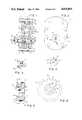
- FIG. 1is a sectional view of a preferred meter showing a magnetic coupling.
- FIG. 2is a side elevation of the meter shown in FIG. 1.
- FIG. 3is a sectional elevation of a preferred magnetic coupling.
- FIG. 4is a perspective view of the preferred magnetic coupling.
- FIG. 5is a cross sectional elevation of a rotor in which the first magnetic coupling is mounted.
- the other rotoris identical except that the recessed area at the left of the rotor is replaced by a solid portion having an extended bore.
- FIG. 6is an elevational plan of the preferred rotor shown in FIG. 5.
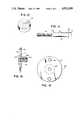
- FIG. 7is an elevational detail of the middle portion of the casing.
- FIG. 8is a cross sectional detail of the preferred nozzle.
- FIG. 9is a cross sectional elevation of a preferred rear cover.
- FIG. 10is a detail of a rotor shaft which is mountable on the rear cover shown in FIG. 9.
- FIG. 11is an elevational cross section of a front cover.
- FIG. 12is a cross sectional detail of an indicator spindle mounting bushing for mounting the recess in the front cover.
- FIG. 13is an end elevation of the bushing of FIG. 12.
- FIG. 14is an elevational detail of the indicator spindle.
- FIG. 15is a cross sectional elevation of an indicator target hub for mounting on the indicator spindle.
- FIG. 16is an elevation detail of the indicator hub.
- a preferred flowmeteris generally indicating by the number 1.
- the flowmeterhas a casing 3 which includes a central portion 5, a rear cover 7, and a front cover 9.
- O-ring seals 11are placed between the sections, and the sections are held together with bolts 13 and nuts 15, thereby forming a chamber 17.
- Rotors 19 and 21are positioned on stub shafts 23 and 25, which have mounting portions 27 positioned in recesses 29 in the rear cover 7. Threaded portions 31 of the shaft extend through the rear cover, and nuts 33 are secured to the threaded portions, holding the shafts assembled.
- O-ring seals 35seal the recesses 29.
- the front cover 9has a threaded recess 37, into which spindle support bushing 39 is threaded.
- An indicator spindle 41is supported in bushing 39.
- An outer end 43 of the spindlesupports an indicator mounting hub 45.
- a friction reducing bushing 44is placed on the shaft between the spindle support bushing 39 and the rotating indicator hub 45.
- An inner end 47 of the shafthas fixed thereto a secondary coupling magnet 49 which turns the shaft in response to rotation of the primary coupling magnet 51.
- the magnetsare separated by a portion of the front cover at the base of the recess 37 and by close spacing of the magnets within their recesses.
- FIG. 2shows a front elevational view of the flowmeter 1 with the front cover 9, the connecting bolts 13, and the indicator hub 45 mounted on the distal end 43 of the indicator spindle.
- FIG. 3shows a cross section of a magnet 50 which is identical to the magnets 49 and 51.
- Magnet 50is preferably a sintered Alnico 2 magnet which weights less than 0.01 of a pound.
- the magnethas a cylindrical body 53 with a bore 54. Pole pieces 55 and 56 extend from the cylindrical portion 53 of the magnet. In preferred installations the pole pieces face each other from the magnets.
- the primary coupling magnet 51 mounted on the rotor 19has its outer cylindrical surface 57 tightly wedged in the recess 59 of the rotor 19.
- the secondary coupling magnet 49has its central bore 54 tightly fitted on the proximal end 47 of the indicator spindle.
- rotor 19has a generally cylindrical central shape and has radially extending lobes 61 and valleys 63 about its, outer periphery.
- the frontal face 65 of the magnetis recessed 67 so that only an extended hub portion 69 bears against the front wall of the chamber, which is the inner wall of the cover, providing a clearance 71.
- a similar recessed portion 67 of the front face 65is provided on the upper rotor 21 to provide a similar clearance 71 between the rotor and the front cover.
- Bores 73extend through the rotors to loosely receive the mounting shafts 23 and 25.
- the bore 73extends entirely through the upper rotor.
- the lower rotoris provided with a recess 59 which is provided with an inner cylindrical portion 75 and outer portion 77.
- the cylindrical portion 53 of the magnetis positioned within the cylindrical portion 75 of the recess.
- lobes 61have generally cylindrical tips 79, and the valleys 63 are generally cylindrical concave valleys having greater radii than the cylindrically curved tips 79.
- the radii of the tips 79are located on a circle around a center of the rotor outward from a circle around the center of the rotor on which the larger radii of the valleys 63 are centered.
- the rotorsare configured so that a boundary layer clearance exists between the tips and valleys when they intermesh during usage.
- the thickness of the rotors, the overall dimensions of the rotors and the relationship between the rotors and stub shaftsprovide small clearance commensurate with free operation and with accurate measuring of the fluids.
- the central section 5 of the housinghas a chamber 17 which is formed from two overlapping cylindrical portions 81.
- An inlet 83 and an outlet 85are provided to open between the cylindrical sections.
- the inlet and outletare threaded 87 to receive nozzles as later will be described.
- Holes 89extend through all of the sections to receive the joining bolts 13.
- Nozzles 91 shown in FIG. 8have a threaded cylindrical portion 93 for threading into threads 87 in the inlet and outlet.
- a cap portion 95abuts a flat outer surface of the central section.
- Bore 97terminates inwardly in four spaced openings 99 in the sloped inner surface 101 of the nozzle to flow fluid in directions other than directly between nozzles.
- the sloped inner surface 101slopes between the non-intermeshing portions of the rotor lobes in an area generally indicated as 103 in FIG. 7 to substantially fill the large void spaces in the center of the chamber.
- the nozzlehas two purposes: to redirect flow and to fill void spaces within the chamber.
- FIG. 9shows a cross sectional elevation of a rear cover 7.
- Rear cover 7has recesses 29 which receive the mounting portions of the stub shafts and has bores 105 which receive the threaded portions of the stub shafts.
- the continuous groove 107receives an O-ring seal 11 as shown in FIG. 1.
- a stub shaft 25 shown in FIG. 10has a bearing portion 109 which extends through bore 23 in a rotor.
- a mounting portion 111fits within recess 29 in the rear cover 7, and groove 113 receives an O-ring seal to seal the recess 29.
- Threaded portion 31extends through the bore in the cover to receive a nut 33 as shown in FIG. 1.
- the front cover 9has a threaded recess 37 which receives the indicator spindle mounting bushing.
- a continuous groove 115receives an O-ring seal 11 which forms a seal between the front cover 9 and the central section 5.
- Recess 37has a base 117 which is approximately 0.050 inch from the inner surface 119 of the front cover.
- FIG. 12An indicator spindle mounting bushing 39 is shown in FIG. 12.
- the bushinghas a threaded portion 121 which is received in the threaded recess 37 in front cover, and has an extended portion 123 with flats 125 which are used to turn the bushing into the front cover recess 37.
- the bushing 39has a central bearing bore 126, which receives a bearing portion of the spindle shaft, and has a recess 127 which receives a magnetic coupling mounted on the spindle shaft. As shown in FIG. 1 the portion 123 of the spindle bushing extends forward from the front cover 9.
- the indicator spindle shaft 41is shown in FIG. 14.
- the shaft 41has a central bearing portion 131 and a magnetic coupling portion 47 and a collar 133 therebetween.
- a distal portion 43 of spindle 41is threaded to receive an indicator hub 45 and locking nut 46 as shown in FIG. 1.
- the anti-friction bushing 44 shown in FIG. 1rests against the step 135 shown in FIG. 14.
- the indicator target hub 45 shown in FIG. 15has a threaded bore 137 which is received on threaded portion 43 of the indicator spindle 41.
- a central portion 139extends along the indicator spindle and a flat edge 141 has threaded holes 143 for receiving a target such as a optical reflector.
- a flat portion 145 of the hubreceives a flat portion of the nut 6 shown in FIG. 1 to lock the hub on the spindle.
- the friction reducing bushing 44 shown in FIG. 1rests against the step portion 147 of the hub.
- the fluid flowmeteris assembled by placing O-rings 27 in the recess 113 of the stub shaft mounting portion 111, and the mounting portions 111 are pushed into the recesses 29 in the rear cover 7. Nuts 33 are threaded on extensions 31 of the shafts and are tightened to secure the stub shafts in the rear cover. The first magnetic coupling is pressed into rotor 19 and rotors 19 and 21 are assembled on the stub shafts.
- the central section 5is placed over the rotors and the front cover 9 is placed on the central section 5. Through openings are aligned, and bolts 13 are inserted in the openings and nuts 15 are secured. Nozzles are inserted in the inlet and outlet and are tightened in place, completing the chamber construction.
- the second magnetic couplingis pressed on the end of the spindle shaft and the spindle shaft is inserted through the spindle bushing.
- the friction reducing bushing 44is added on the end of the spindle shaft, and the indicator target hub 45 is threaded onto the end of the spindle shaft and locked thereon with nut 46.
- the bushing 39is threaded into the recess, and the front cover and the meter is ready for use.
- fluidflows through a nozzle into the chamber and flows outward and around the periphery of the chambers, turning the rotors, and flows outward through the outlet nozzle and through the outlet.
- the first magnetic couplingturns, forcing the second magnetic coupling and the spindle shaft to turn, turning the indicator hub and an indicator mounted thereon.
- the indicator on the hubis read, such as by retro-reflective optical readers.
Landscapes
- Physics & Mathematics (AREA)
- Fluid Mechanics (AREA)
- General Physics & Mathematics (AREA)
- Measuring Volume Flow (AREA)
Abstract
Description
Claims (19)
Priority Applications (1)
| Application Number | Priority Date | Filing Date | Title |
|---|---|---|---|
| US07/231,684US4911010A (en) | 1988-08-12 | 1988-08-12 | Fluid flowmeter |
Applications Claiming Priority (1)
| Application Number | Priority Date | Filing Date | Title |
|---|---|---|---|
| US07/231,684US4911010A (en) | 1988-08-12 | 1988-08-12 | Fluid flowmeter |
Publications (1)
| Publication Number | Publication Date |
|---|---|
| US4911010Atrue US4911010A (en) | 1990-03-27 |
Family
ID=22870252
Family Applications (1)
| Application Number | Title | Priority Date | Filing Date |
|---|---|---|---|
| US07/231,684Expired - LifetimeUS4911010A (en) | 1988-08-12 | 1988-08-12 | Fluid flowmeter |
Country Status (1)
| Country | Link |
|---|---|
| US (1) | US4911010A (en) |
Cited By (9)
| Publication number | Priority date | Publication date | Assignee | Title |
|---|---|---|---|---|
| US5251785A (en)* | 1992-02-06 | 1993-10-12 | The Lubrizol Corporation | Additive injection system and method |
| US5559288A (en)* | 1990-12-18 | 1996-09-24 | Vse Schweisstechnik Gmbh | Volume sensor for liquids using toothed meter wheels |
| US6250151B1 (en)* | 1995-10-30 | 2001-06-26 | Marconi Commerce Systems Gmbh & Co. Kg | Fluid flow meter incorporating magnetic detector |
| US6644947B2 (en) | 2002-03-14 | 2003-11-11 | Tuthill Corporation | Wave tooth gears using identical non-circular conjugating pitch curves |
| US20030236489A1 (en)* | 2002-06-21 | 2003-12-25 | Baxter International, Inc. | Method and apparatus for closed-loop flow control system |
| US6796173B1 (en) | 1998-10-09 | 2004-09-28 | Fti Flow Technology, Inc. | Fuel flowmeter |
| US20050035914A1 (en)* | 2001-03-09 | 2005-02-17 | Dan Winter | Meter register |
| US20060162467A1 (en)* | 2004-09-23 | 2006-07-27 | Arad Measuring Technologies, Ltd. | Meter register having an encoder |
| US20200011719A1 (en)* | 2018-07-09 | 2020-01-09 | Elbi International S.P.A. | Volumetric flow meter |
Citations (29)
| Publication number | Priority date | Publication date | Assignee | Title |
|---|---|---|---|---|
| US294026A (en)* | 1884-02-26 | Rotary meter | ||
| US386795A (en)* | 1888-07-31 | Rotary water-meter | ||
| US2383226A (en)* | 1943-09-20 | 1945-08-21 | John A Swindle | Liquid meter |
| US3255630A (en)* | 1963-11-04 | 1966-06-14 | Rockwell Mfg Co | Positive displacement rotary gas meter |
| US3342071A (en)* | 1965-06-07 | 1967-09-19 | Dresser Ind | Self-powered meter rate compensator |
| US3413851A (en)* | 1966-09-29 | 1968-12-03 | Hersey Sparling Meter Company | Nutating disk meters |
| US3554032A (en)* | 1967-01-03 | 1971-01-12 | Singer Co | Rotary fluid meter |
| US3695106A (en)* | 1970-07-02 | 1972-10-03 | Daniel Ind Inc | Gas turbine meter |
| US3707872A (en)* | 1971-05-10 | 1973-01-02 | Gamon Calmet Ind Inc | Compound fluid meter |
| US3811323A (en)* | 1971-09-08 | 1974-05-21 | Hersey Prod Inc | Liquid meter |
| US3858448A (en)* | 1969-07-03 | 1975-01-07 | Rockwell International Corp | Magnetic drive for meter |
| US4007635A (en)* | 1974-06-28 | 1977-02-15 | Siemens Aktiengesellschaft | Fluid volume apparatus for measuring a fluid under pressure |
| US4023410A (en)* | 1974-07-24 | 1977-05-17 | Aquametro Ag | Fluid flow meter |
| DE2830563A1 (en)* | 1978-07-12 | 1980-01-24 | Meinecke Ag H | Woltmann flowmeter with vane wheel - is coupled to counter by magnetic coupling whose two parts have different dia. and numbers of magnets |
| US4210410A (en)* | 1977-11-17 | 1980-07-01 | Tokico Ltd. | Volumetric type flowmeter having circular and involute tooth shape rotors |
| JPS5587914A (en)* | 1978-12-26 | 1980-07-03 | Akitoshi Kitano | Displacement flow meter |
| JPS5590819A (en)* | 1978-12-28 | 1980-07-09 | Seibu Suido Kiki Seisakusho:Kk | Ground type upright service-water meter |
| US4224015A (en)* | 1977-01-19 | 1980-09-23 | Oval Engineering Co., Ltd. | Positive displacement flow meter with helical-toothed rotors |
| EP0031317A1 (en)* | 1979-12-21 | 1981-07-01 | ELIN-UNION Aktiengesellschaft für elektrische Industrie | Apparatus for measuring the quantity of a heat transporting medium flowing through a conduit |
| US4295369A (en)* | 1980-04-10 | 1981-10-20 | Geosource Inc. | Dual magnetic drive for gear meters |
| JPS5773624A (en)* | 1980-10-24 | 1982-05-08 | Aichi Tokei Denki Co Ltd | Prevention device for leakage of twin rotor type flow meter |
| US4329130A (en)* | 1978-07-03 | 1982-05-11 | Oval Engineering Company Limited | Flow meter with helical toothed rotors having no pulsation and zero contact pressure |
| US4345480A (en)* | 1978-02-21 | 1982-08-24 | Basham Edward R | Rotary flow meter |
| US4409829A (en)* | 1980-11-27 | 1983-10-18 | Kracht Pumpen-Und Motorenfabrik Gmbh & Co. Kg | Volume flow sensor of the gear wheel motor type |
| JPS58184514A (en)* | 1982-04-22 | 1983-10-28 | Oval Eng Co Ltd | Flow rate signal generator |
| US4451207A (en)* | 1981-04-01 | 1984-05-29 | Hydrotechnik Gmbh | Turbine rotor for a flow meter |
| US4489615A (en)* | 1983-01-04 | 1984-12-25 | Breckland Meters Limited | Fluid flow meter |
| US4579008A (en)* | 1983-06-18 | 1986-04-01 | Bopp & Reuther Gmbh | Electromagnetic pulse pick-up arrangement in a flow meter |
| US4641522A (en)* | 1985-04-03 | 1987-02-10 | Lopresti William J | Bearing-less positive displacement flowmeter |
- 1988
- 1988-08-12USUS07/231,684patent/US4911010A/ennot_activeExpired - Lifetime
Patent Citations (29)
| Publication number | Priority date | Publication date | Assignee | Title |
|---|---|---|---|---|
| US294026A (en)* | 1884-02-26 | Rotary meter | ||
| US386795A (en)* | 1888-07-31 | Rotary water-meter | ||
| US2383226A (en)* | 1943-09-20 | 1945-08-21 | John A Swindle | Liquid meter |
| US3255630A (en)* | 1963-11-04 | 1966-06-14 | Rockwell Mfg Co | Positive displacement rotary gas meter |
| US3342071A (en)* | 1965-06-07 | 1967-09-19 | Dresser Ind | Self-powered meter rate compensator |
| US3413851A (en)* | 1966-09-29 | 1968-12-03 | Hersey Sparling Meter Company | Nutating disk meters |
| US3554032A (en)* | 1967-01-03 | 1971-01-12 | Singer Co | Rotary fluid meter |
| US3858448A (en)* | 1969-07-03 | 1975-01-07 | Rockwell International Corp | Magnetic drive for meter |
| US3695106A (en)* | 1970-07-02 | 1972-10-03 | Daniel Ind Inc | Gas turbine meter |
| US3707872A (en)* | 1971-05-10 | 1973-01-02 | Gamon Calmet Ind Inc | Compound fluid meter |
| US3811323A (en)* | 1971-09-08 | 1974-05-21 | Hersey Prod Inc | Liquid meter |
| US4007635A (en)* | 1974-06-28 | 1977-02-15 | Siemens Aktiengesellschaft | Fluid volume apparatus for measuring a fluid under pressure |
| US4023410A (en)* | 1974-07-24 | 1977-05-17 | Aquametro Ag | Fluid flow meter |
| US4224015A (en)* | 1977-01-19 | 1980-09-23 | Oval Engineering Co., Ltd. | Positive displacement flow meter with helical-toothed rotors |
| US4210410A (en)* | 1977-11-17 | 1980-07-01 | Tokico Ltd. | Volumetric type flowmeter having circular and involute tooth shape rotors |
| US4345480A (en)* | 1978-02-21 | 1982-08-24 | Basham Edward R | Rotary flow meter |
| US4329130A (en)* | 1978-07-03 | 1982-05-11 | Oval Engineering Company Limited | Flow meter with helical toothed rotors having no pulsation and zero contact pressure |
| DE2830563A1 (en)* | 1978-07-12 | 1980-01-24 | Meinecke Ag H | Woltmann flowmeter with vane wheel - is coupled to counter by magnetic coupling whose two parts have different dia. and numbers of magnets |
| JPS5587914A (en)* | 1978-12-26 | 1980-07-03 | Akitoshi Kitano | Displacement flow meter |
| JPS5590819A (en)* | 1978-12-28 | 1980-07-09 | Seibu Suido Kiki Seisakusho:Kk | Ground type upright service-water meter |
| EP0031317A1 (en)* | 1979-12-21 | 1981-07-01 | ELIN-UNION Aktiengesellschaft für elektrische Industrie | Apparatus for measuring the quantity of a heat transporting medium flowing through a conduit |
| US4295369A (en)* | 1980-04-10 | 1981-10-20 | Geosource Inc. | Dual magnetic drive for gear meters |
| JPS5773624A (en)* | 1980-10-24 | 1982-05-08 | Aichi Tokei Denki Co Ltd | Prevention device for leakage of twin rotor type flow meter |
| US4409829A (en)* | 1980-11-27 | 1983-10-18 | Kracht Pumpen-Und Motorenfabrik Gmbh & Co. Kg | Volume flow sensor of the gear wheel motor type |
| US4451207A (en)* | 1981-04-01 | 1984-05-29 | Hydrotechnik Gmbh | Turbine rotor for a flow meter |
| JPS58184514A (en)* | 1982-04-22 | 1983-10-28 | Oval Eng Co Ltd | Flow rate signal generator |
| US4489615A (en)* | 1983-01-04 | 1984-12-25 | Breckland Meters Limited | Fluid flow meter |
| US4579008A (en)* | 1983-06-18 | 1986-04-01 | Bopp & Reuther Gmbh | Electromagnetic pulse pick-up arrangement in a flow meter |
| US4641522A (en)* | 1985-04-03 | 1987-02-10 | Lopresti William J | Bearing-less positive displacement flowmeter |
Cited By (28)
| Publication number | Priority date | Publication date | Assignee | Title |
|---|---|---|---|---|
| US5559288A (en)* | 1990-12-18 | 1996-09-24 | Vse Schweisstechnik Gmbh | Volume sensor for liquids using toothed meter wheels |
| US5344044A (en)* | 1992-02-06 | 1994-09-06 | The Lubrizol Corporation | Additive injection system and method |
| US5251785A (en)* | 1992-02-06 | 1993-10-12 | The Lubrizol Corporation | Additive injection system and method |
| US6250151B1 (en)* | 1995-10-30 | 2001-06-26 | Marconi Commerce Systems Gmbh & Co. Kg | Fluid flow meter incorporating magnetic detector |
| US6796173B1 (en) | 1998-10-09 | 2004-09-28 | Fti Flow Technology, Inc. | Fuel flowmeter |
| US20080209985A1 (en)* | 2001-03-09 | 2008-09-04 | Arad Measuring Technologies Ltd. | Meter register |
| US8109131B2 (en) | 2001-03-09 | 2012-02-07 | Arad Measuring Technologies Ltd. | Meter register transmitting flow rate warning |
| US20050035914A1 (en)* | 2001-03-09 | 2005-02-17 | Dan Winter | Meter register |
| US10330507B2 (en) | 2001-03-09 | 2019-06-25 | Arad Measuring Technologies Ltd. | Meter register and utility meter having wireless remote reading arrangement |
| USRE47407E1 (en) | 2001-03-09 | 2019-05-28 | Arad Measuring Technologies Ltd. | Meter register transmitting flow rate warning |
| US7126551B2 (en) | 2001-03-09 | 2006-10-24 | Arad Measuring Technologies Ltd | Meter register |
| US20070109209A1 (en)* | 2001-03-09 | 2007-05-17 | Arad Measuring Technologies Ltd. | Meter register |
| US9356334B2 (en) | 2001-03-09 | 2016-05-31 | Arad Measuring Technologies Ltd. | Meter register transmitting flow rate warning |
| US7343795B2 (en) | 2001-03-09 | 2008-03-18 | Arad Measuring Technologies Ltd | Meter register and meter register tampering detector |
| US6644947B2 (en) | 2002-03-14 | 2003-11-11 | Tuthill Corporation | Wave tooth gears using identical non-circular conjugating pitch curves |
| US20080243058A1 (en)* | 2002-06-21 | 2008-10-02 | Jacobson James D | Fluid delivery system and flow control therefor |
| US20030236489A1 (en)* | 2002-06-21 | 2003-12-25 | Baxter International, Inc. | Method and apparatus for closed-loop flow control system |
| US20080255502A1 (en)* | 2002-06-21 | 2008-10-16 | Jacobson James D | Fluid delivery system and flow control therefor |
| US7879025B2 (en) | 2002-06-21 | 2011-02-01 | Baxter International Inc. | Fluid delivery system and flow control therefor |
| US20080243057A1 (en)* | 2002-06-21 | 2008-10-02 | Jacobson James D | Fluid delivery system and flow control therefor |
| US8226597B2 (en) | 2002-06-21 | 2012-07-24 | Baxter International, Inc. | Fluid delivery system and flow control therefor |
| US8231566B2 (en) | 2002-06-21 | 2012-07-31 | Baxter International, Inc. | Fluid delivery system and flow control therefor |
| US8672876B2 (en) | 2002-06-21 | 2014-03-18 | Baxter International Inc. | Fluid delivery system and flow control therefor |
| US20060142692A1 (en)* | 2002-06-21 | 2006-06-29 | Baxter International, Inc. | Fluid delivery system and flow control therefor |
| US7267014B2 (en) | 2004-09-23 | 2007-09-11 | Arad Measuring Technologies Ltd. | Meter register having an encoder |
| US20060162467A1 (en)* | 2004-09-23 | 2006-07-27 | Arad Measuring Technologies, Ltd. | Meter register having an encoder |
| US20200011719A1 (en)* | 2018-07-09 | 2020-01-09 | Elbi International S.P.A. | Volumetric flow meter |
| US10871389B2 (en)* | 2018-07-09 | 2020-12-22 | Elbi International S.P.A. | Volumetric flow meter having a cartridge casing inserted in a duct with intermeshed rotors |
Similar Documents
| Publication | Publication Date | Title |
|---|---|---|
| US6412338B2 (en) | On-board rotational viscometers | |
| US5992230A (en) | Dual rotor flow meter | |
| US4911010A (en) | Fluid flowmeter | |
| US20160238419A1 (en) | Flow measuring device for lubrication systems | |
| US4996888A (en) | Fluid flowmeter | |
| US5275043A (en) | Positive displacement flowmeter | |
| US5325715A (en) | Fluid flowmeter | |
| US4030357A (en) | Metering of fluid flows | |
| US5027653A (en) | Flowmeters having rotors with grooved bores and lands | |
| JP3646007B2 (en) | Cyclone turbine flow meter | |
| US4534227A (en) | Device for measuring the flow of a fluid | |
| WO2000054025A1 (en) | On-board rotational viscometers | |
| CN111721369B (en) | Impeller device and turbine flowmeter | |
| EP0399634A2 (en) | Viscometer | |
| KR100306214B1 (en) | Device for measuring quantity of flow | |
| JPH02170056A (en) | Capacity meter | |
| DE4208869A1 (en) | Volumetric fuel flowmeter - has displacement meter consisting of engaged, threaded screw spindles, inductive electromagnetic sensors close to grooves in one spindle | |
| US4515022A (en) | Flow monitoring method and device | |
| CN222505515U (en) | Double screw flowmeter | |
| AU2179992A (en) | Turbine flow meter | |
| JPH082577Y2 (en) | Volumetric flow meter | |
| JPH0323533Y2 (en) | ||
| CN104568021A (en) | Three-screw-rod flow meter | |
| CN222926236U (en) | High-precision double-screw flowmeter | |
| CN87216916U (en) | Floating ring scrape flow meter |
Legal Events
| Date | Code | Title | Description |
|---|---|---|---|
| AS | Assignment | Owner name:FLOWDATA, INC., A TX CORP., TEXAS Free format text:ASSIGNMENT OF ASSIGNORS INTEREST.;ASSIGNOR:FORAN, CHARLES D. JR.;REEL/FRAME:005003/0308 Effective date:19880809 | |
| AS | Assignment | Owner name:FLOWDATA, INC., 15510 WRIGHT BROTHERS DRIVE, DALLA Free format text:ASSIGNMENT OF ASSIGNORS INTEREST.;ASSIGNORS:FORAN, CHARLES D. JR.;LOPRESTI, WILLIAM J.;REEL/FRAME:004984/0717 Effective date:19880809 Owner name:FLOWDATA, INC., A TX CORP., TEXAS Free format text:ASSIGNMENT OF ASSIGNORS INTEREST;ASSIGNORS:FORAN, CHARLES D. JR.;LOPRESTI, WILLIAM J.;REEL/FRAME:004984/0717 Effective date:19880809 | |
| STCF | Information on status: patent grant | Free format text:PATENTED CASE | |
| FPAY | Fee payment | Year of fee payment:4 | |
| FPAY | Fee payment | Year of fee payment:8 | |
| AS | Assignment | Owner name:FTI FLOW TECHNOLOGY, INC., GEORGIA Free format text:MERGER/CHANGE OF NAME;ASSIGNOR:FLOWDATA, INC.;REEL/FRAME:011260/0508 Effective date:20000214 | |
| FPAY | Fee payment | Year of fee payment:12 |