US4910658A - Real time process controller with serial I/O bus - Google Patents
Real time process controller with serial I/O busDownload PDFInfo
- Publication number
- US4910658A US4910658AUS07/251,008US25100888AUS4910658AUS 4910658 AUS4910658 AUS 4910658AUS 25100888 AUS25100888 AUS 25100888AUS 4910658 AUS4910658 AUS 4910658A
- Authority
- US
- United States
- Prior art keywords
- control
- modules
- control unit
- block
- module
- Prior art date
- Legal status (The legal status is an assumption and is not a legal conclusion. Google has not performed a legal analysis and makes no representation as to the accuracy of the status listed.)
- Expired - Lifetime
Links
- 238000000034methodMethods0.000titleclaimsabstractdescription130
- 230000008569processEffects0.000titleclaimsabstractdescription104
- 239000004020conductorSubstances0.000claimsabstractdescription47
- 238000004886process controlMethods0.000claimsabstractdescription39
- 238000012544monitoring processMethods0.000claimsabstractdescription18
- 238000004891communicationMethods0.000claimsabstractdescription15
- 230000003993interactionEffects0.000claimsabstractdescription5
- 230000006870functionEffects0.000claimsdescription45
- 230000004044responseEffects0.000claimsdescription22
- 230000008859changeEffects0.000claimsdescription9
- 230000000007visual effectEffects0.000claimsdescription8
- 230000005540biological transmissionEffects0.000claimsdescription7
- 230000000694effectsEffects0.000claimsdescription6
- 230000009471actionEffects0.000claimsdescription5
- 230000008520organizationEffects0.000claimsdescription4
- 238000011112process operationMethods0.000claimsdescription3
- 230000001934delayEffects0.000claimsdescription2
- 238000001514detection methodMethods0.000claimsdescription2
- 238000004519manufacturing processMethods0.000claims1
- 230000004048modificationEffects0.000abstractdescription4
- 238000012986modificationMethods0.000abstractdescription4
- 238000012360testing methodMethods0.000description21
- 238000012545processingMethods0.000description11
- 238000005516engineering processMethods0.000description8
- 238000002405diagnostic procedureMethods0.000description7
- 230000006872improvementEffects0.000description6
- 238000010586diagramMethods0.000description5
- 238000012937correctionMethods0.000description4
- 230000002452interceptive effectEffects0.000description4
- 238000012423maintenanceMethods0.000description4
- 238000005452bendingMethods0.000description3
- 238000010276constructionMethods0.000description3
- 230000000994depressogenic effectEffects0.000description3
- 238000013461designMethods0.000description3
- 239000004065semiconductorSubstances0.000description3
- 230000003068static effectEffects0.000description3
- 230000000977initiatory effectEffects0.000description2
- 239000000463materialSubstances0.000description2
- 239000011159matrix materialSubstances0.000description2
- 230000007246mechanismEffects0.000description2
- 230000036961partial effectEffects0.000description2
- 230000003449preventive effectEffects0.000description2
- 241000238631HexapodaSpecies0.000description1
- 230000003213activating effectEffects0.000description1
- 230000004913activationEffects0.000description1
- 230000003044adaptive effectEffects0.000description1
- 230000003466anti-cipated effectEffects0.000description1
- 230000008901benefitEffects0.000description1
- 230000002457bidirectional effectEffects0.000description1
- 230000000881depressing effectEffects0.000description1
- 238000012938design processMethods0.000description1
- 238000003745diagnosisMethods0.000description1
- 238000007435diagnostic evaluationMethods0.000description1
- 238000009432framingMethods0.000description1
- 238000011900installation processMethods0.000description1
- 230000010354integrationEffects0.000description1
- 238000003825pressingMethods0.000description1
- 230000001681protective effectEffects0.000description1
- 230000008439repair processEffects0.000description1
- 230000008672reprogrammingEffects0.000description1
- 239000007787solidSubstances0.000description1
Images


Classifications
- G—PHYSICS
- G05—CONTROLLING; REGULATING
- G05B—CONTROL OR REGULATING SYSTEMS IN GENERAL; FUNCTIONAL ELEMENTS OF SUCH SYSTEMS; MONITORING OR TESTING ARRANGEMENTS FOR SUCH SYSTEMS OR ELEMENTS
- G05B19/00—Programme-control systems
- G05B19/02—Programme-control systems electric
- G05B19/04—Programme control other than numerical control, i.e. in sequence controllers or logic controllers
- G05B19/05—Programmable logic controllers, e.g. simulating logic interconnections of signals according to ladder diagrams or function charts
- G05B19/056—Programming the PLC
- G—PHYSICS
- G05—CONTROLLING; REGULATING
- G05B—CONTROL OR REGULATING SYSTEMS IN GENERAL; FUNCTIONAL ELEMENTS OF SUCH SYSTEMS; MONITORING OR TESTING ARRANGEMENTS FOR SUCH SYSTEMS OR ELEMENTS
- G05B19/00—Programme-control systems
- G05B19/02—Programme-control systems electric
- G05B19/04—Programme control other than numerical control, i.e. in sequence controllers or logic controllers
- G05B19/05—Programmable logic controllers, e.g. simulating logic interconnections of signals according to ladder diagrams or function charts
- G05B19/054—Input/output
- G—PHYSICS
- G05—CONTROLLING; REGULATING
- G05B—CONTROL OR REGULATING SYSTEMS IN GENERAL; FUNCTIONAL ELEMENTS OF SUCH SYSTEMS; MONITORING OR TESTING ARRANGEMENTS FOR SUCH SYSTEMS OR ELEMENTS
- G05B19/00—Programme-control systems
- G05B19/02—Programme-control systems electric
- G05B19/04—Programme control other than numerical control, i.e. in sequence controllers or logic controllers
- G05B19/05—Programmable logic controllers, e.g. simulating logic interconnections of signals according to ladder diagrams or function charts
- G05B19/058—Safety, monitoring
- G—PHYSICS
- G05—CONTROLLING; REGULATING
- G05B—CONTROL OR REGULATING SYSTEMS IN GENERAL; FUNCTIONAL ELEMENTS OF SUCH SYSTEMS; MONITORING OR TESTING ARRANGEMENTS FOR SUCH SYSTEMS OR ELEMENTS
- G05B2219/00—Program-control systems
- G05B2219/10—Plc systems
- G05B2219/11—Plc I-O input output
- G05B2219/1103—Special, intelligent I-O processor, also plc can only access via processor
- G—PHYSICS
- G05—CONTROLLING; REGULATING
- G05B—CONTROL OR REGULATING SYSTEMS IN GENERAL; FUNCTIONAL ELEMENTS OF SUCH SYSTEMS; MONITORING OR TESTING ARRANGEMENTS FOR SUCH SYSTEMS OR ELEMENTS
- G05B2219/00—Program-control systems
- G05B2219/10—Plc systems
- G05B2219/11—Plc I-O input output
- G05B2219/1127—Selector for I-O, multiplex for I-O
- G—PHYSICS
- G05—CONTROLLING; REGULATING
- G05B—CONTROL OR REGULATING SYSTEMS IN GENERAL; FUNCTIONAL ELEMENTS OF SUCH SYSTEMS; MONITORING OR TESTING ARRANGEMENTS FOR SUCH SYSTEMS OR ELEMENTS
- G05B2219/00—Program-control systems
- G05B2219/10—Plc systems
- G05B2219/11—Plc I-O input output
- G05B2219/1129—Serial addressed modules on bus
- G—PHYSICS
- G05—CONTROLLING; REGULATING
- G05B—CONTROL OR REGULATING SYSTEMS IN GENERAL; FUNCTIONAL ELEMENTS OF SUCH SYSTEMS; MONITORING OR TESTING ARRANGEMENTS FOR SUCH SYSTEMS OR ELEMENTS
- G05B2219/00—Program-control systems
- G05B2219/10—Plc systems
- G05B2219/13—Plc programming
- G05B2219/13031—Use of touch screen
- G—PHYSICS
- G05—CONTROLLING; REGULATING
- G05B—CONTROL OR REGULATING SYSTEMS IN GENERAL; FUNCTIONAL ELEMENTS OF SUCH SYSTEMS; MONITORING OR TESTING ARRANGEMENTS FOR SUCH SYSTEMS OR ELEMENTS
- G05B2219/00—Program-control systems
- G05B2219/10—Plc systems
- G05B2219/13—Plc programming
- G05B2219/13032—Different menus on screen, softkeys
- G—PHYSICS
- G05—CONTROLLING; REGULATING
- G05B—CONTROL OR REGULATING SYSTEMS IN GENERAL; FUNCTIONAL ELEMENTS OF SUCH SYSTEMS; MONITORING OR TESTING ARRANGEMENTS FOR SUCH SYSTEMS OR ELEMENTS
- G05B2219/00—Program-control systems
- G05B2219/10—Plc systems
- G05B2219/13—Plc programming
- G05B2219/13086—Priority interrupt
- G—PHYSICS
- G05—CONTROLLING; REGULATING
- G05B—CONTROL OR REGULATING SYSTEMS IN GENERAL; FUNCTIONAL ELEMENTS OF SUCH SYSTEMS; MONITORING OR TESTING ARRANGEMENTS FOR SUCH SYSTEMS OR ELEMENTS
- G05B2219/00—Program-control systems
- G05B2219/10—Plc systems
- G05B2219/13—Plc programming
- G05B2219/13171—Portable, detachable programming unit
- G—PHYSICS
- G05—CONTROLLING; REGULATING
- G05B—CONTROL OR REGULATING SYSTEMS IN GENERAL; FUNCTIONAL ELEMENTS OF SUCH SYSTEMS; MONITORING OR TESTING ARRANGEMENTS FOR SUCH SYSTEMS OR ELEMENTS
- G05B2219/00—Program-control systems
- G05B2219/10—Plc systems
- G05B2219/15—Plc structure of the system
- G05B2219/15019—RS232 serial
- G—PHYSICS
- G05—CONTROLLING; REGULATING
- G05B—CONTROL OR REGULATING SYSTEMS IN GENERAL; FUNCTIONAL ELEMENTS OF SUCH SYSTEMS; MONITORING OR TESTING ARRANGEMENTS FOR SUCH SYSTEMS OR ELEMENTS
- G05B2219/00—Program-control systems
- G05B2219/10—Plc systems
- G05B2219/15—Plc structure of the system
- G05B2219/15047—Colour display
- G—PHYSICS
- G05—CONTROLLING; REGULATING
- G05B—CONTROL OR REGULATING SYSTEMS IN GENERAL; FUNCTIONAL ELEMENTS OF SUCH SYSTEMS; MONITORING OR TESTING ARRANGEMENTS FOR SUCH SYSTEMS OR ELEMENTS
- G05B2219/00—Program-control systems
- G05B2219/20—Pc systems
- G05B2219/23—Pc programming
- G05B2219/23378—Touch sensitive key
- G—PHYSICS
- G05—CONTROLLING; REGULATING
- G05B—CONTROL OR REGULATING SYSTEMS IN GENERAL; FUNCTIONAL ELEMENTS OF SUCH SYSTEMS; MONITORING OR TESTING ARRANGEMENTS FOR SUCH SYSTEMS OR ELEMENTS
- G05B2219/00—Program-control systems
- G05B2219/20—Pc systems
- G05B2219/25—Pc structure of the system
- G05B2219/25096—Detect addresses of connected I-O, modules
- G—PHYSICS
- G05—CONTROLLING; REGULATING
- G05B—CONTROL OR REGULATING SYSTEMS IN GENERAL; FUNCTIONAL ELEMENTS OF SUCH SYSTEMS; MONITORING OR TESTING ARRANGEMENTS FOR SUCH SYSTEMS OR ELEMENTS
- G05B2219/00—Program-control systems
- G05B2219/20—Pc systems
- G05B2219/25—Pc structure of the system
- G05B2219/25178—Serial communication, data, also repeater
- G—PHYSICS
- G05—CONTROLLING; REGULATING
- G05B—CONTROL OR REGULATING SYSTEMS IN GENERAL; FUNCTIONAL ELEMENTS OF SUCH SYSTEMS; MONITORING OR TESTING ARRANGEMENTS FOR SUCH SYSTEMS OR ELEMENTS
- G05B2219/00—Program-control systems
- G05B2219/20—Pc systems
- G05B2219/25—Pc structure of the system
- G05B2219/25315—Module, sequence from module to module, structure
- G—PHYSICS
- G05—CONTROLLING; REGULATING
- G05B—CONTROL OR REGULATING SYSTEMS IN GENERAL; FUNCTIONAL ELEMENTS OF SUCH SYSTEMS; MONITORING OR TESTING ARRANGEMENTS FOR SUCH SYSTEMS OR ELEMENTS
- G05B2219/00—Program-control systems
- G05B2219/20—Pc systems
- G05B2219/25—Pc structure of the system
- G05B2219/25324—Modules connected to serial bus
Definitions
- the present inventionrelates to automated process control systems, and in particular, to a user interactive process control system which is rapidly expandable and adaptable for use in many different types of processes.
- process controls systemshave evolved from relatively simple individual controllers for specific process conditions to very large integrated systems including digital processing equipment.
- large control panelswere often required often, complex control systems may have control panels which are several feet in length, with the process information and operator control devices located at various places along the panel.
- the inventioncomprises a novel system and method for controlling processes which is simple in construction, readily expandable, easily adaptable for new applications, user interactive, which provides substantially immediate identification of actual and potential failures, and which makes available diagnostic messages for assisting a user in correcting the condition causing the failure.
- the systemincludes a plurality of serially addressable modules which each function independently from a central control unit in monitoring selected process devices and in identifying failure conditions affecting the device and communicating same to the control unit. Specifically, the modules regularly provide updated information as to the status of the process device to which they are electrically and/or mechanically connected. If a failure condition is detected, this information is communicated immediately to the user by means of a priority interrupt through the central controller. The interrupt is initiated by that serially addressable module which detects the failure condition. The modules also detect and identify to the user intermittent faults in order to permit preventive maintenance. The modules also provide a means through which the operation of the process device may be controlled.
- the serially addressable modulesare electrically interconnected in series configuration through a multi-conductor bus such as ribbon cable which carries bidirectional serial data and power to each component in the system.
- the serial buselectrically connects the components to a control unit which comprises a microprocessor system, a CRT display and a touch screen device for operator/programmer I/O.
- the control unitfunctions as an interface between a user and the components of the system, permitting interactive user monitoring of specified process devices, and communicating status information from the modules to the user.
- the control unitalso provides diagnostic information when a failure or intermittent fault has been detected.
- the moduleprovides an indication of the type of failure and its location, and the diagnostic information includes instructions as to corrective measures which should be taken.
- the serially addressable modulesmay be easily secured at substantially any desired location on the multi-conductor bus.
- the systemmay be expanded or modified by adding or moving modules, which snap into electrical connection with the multi-conductor bus at any of numerous locations on that bus.
- the modulesare each internally assigned a desired address to identify specific units.
- the addressis also used for establishing priority among the plural modules on a single bus for accessing the control unit on a priority interrupt basis.
- the modulesmay be individually accessed through the control unit through use of the appropriate address which identifies the selected module.
- the control unitAfter adding a module on the control line and assigning it an address, the control unit is programmed to include the particular address, and the system has then been expanded to include the new module, and to monitor and control the device associated with the new module. Particular device parameters to be monitored and/or controlled are also specified in the module and in the control unit.
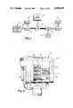
- FIG. 1is a schematic diagram of one preferred embodiment of the system of the present invention.
- FIG. 2is a perspective view of a presently preferred embodiment of a system control unit of the present invention.
- FIG. 3is an exploded perspective view of a presently preferred embodiment of a serially addressable module and a multi-conductor serial bus of the present invention.
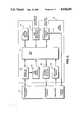
- FIG. 4is a block diagram illustrating the components of a system control unit that may be used in accordance with the system and method of the present invention.
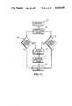
- FIG. 5is a block diagram illustrating the components of a serially addressable module that may be used in accordance with the system and method of the present invention.
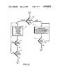
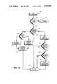
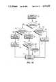
- FIGS. 6 through 11are flow diagrams illustrating the operation of the system control unit of the present invention.
- FIGS. 12 through 16are flow diagrams illustrating the operation of the serially addressable module of the present invention.
- Control unit 20functions as a central control unit for the system, and also as an interface between the user and the system for receiving instructions from users for system operation, and for communicating status and other system information to the user.
- Data bus 22functions as a communications medium for carrying signals between the control unit 20 and one or more serially addressable modules (SAMS) 24 which are electrically connected to the data bus 22 a selected locations.
- SAMSserially addressable modules
- Each of the SAMS 24is electrically connected to an element of the controlled process system, such as a valve 26 or limit switch 28.
- the moduleseach include components which function independently from the control unit 20 to periodically monitor and retain the status of the process element to which the SAM is connected.
- the process elements 26 and 28may be independently monitored and the status of those elements may be communicated via data bus 22 to the control unit 20.
- signals directed to the control of elements 26 and 28can be communicated from control unit 20 to the respective SAMS 24 via data bus 22.
- the configuration of the multiplexed serial data bus 22 and the modules 24 on that buspermit communication between each of the SAMS 24 and the control unit 20 through that single serial data bus 22.
- the control unit 20may communicate with selected SAMS 24 by addressing the selected SAMS 24 with a series of electrical pulses communicated from control unit 20 onto bus 22 in serial fashion along selected wires of bus 22.
- This serial configurationallows SAMS 24 to be added or deleted from the system by merely clipping them to, or removing them from, a selected location along bus 22, and revising the data in the controller 20 to properly reflect the changed circumstances.
- the series configurationprovides for increased versatility in the expansion of the system, as well as in adapting the system for new or different applications.
- the system control unit 20may be described on a functional level by reference to FIG. 2, which illustrates one preferred embodiment of the control unit 20 as it is configured for control of a tube bending process.
- the control unit 20acts as a control interface between the user and the various elements of the process to be controlled.
- the control unit 20provides a visual indication of the status of selected elements, provides instructions as to location and remedies for system failures, and receives control information from the user for controlling the process.
- the particular process elements to be monitored, the information produced in response to particular monitored conditions, and also the control commands to be provided to the system by the usermay be initially programmed into the machine by the user, and modified at any time.
- the systemmay be adapted for control of any of numerous different processes, and may be readily expanded to control more elements or functions in a given process.
- control unit 20Many of the control functions of control unit 20 are accomplished by means of a touch screen 30 of the type which comprises the screen of a cathode ray tube for visually presenting information, and which receives input from the user by detecting physical contact with, or the presence of an object such as a wand or figure in proximity to, a specific location on the screen 30.
- the touch screen 30utilizes infrared emitters/detectors and decode logic for scanning the surface of the screen to detect and identify the coordinate location of objects contacting the screen.
- Such touch screen technologyis well-known by those skilled in the technology, and is commercially available in many different configurations for use in many different applications.
- touch screen 30The information to be presented on touch screen 30 in a given situation, as well as its organization, may be determined by the user and is programmed into the system by the user.
- a portion of the touch screen 30is designated as a touch switch labeled "EDITOR" 32.
- the usertouches EDITOR 32 to create a machine sequencing program, wherein the system interacts with the user to identify lines, numbers and symbols which are organized by the user to define a relay or ladder logic representation of the desired machine sequence.
- the useralso creates displays on the screen 30 which represent, for example, touch switches which may be activated by the user to initiate the monitoring and control of selected process elements. By this means, the user creates his own operator's panel.
- MANUAL 34Another section of the screen 30 is designated as a touch switch labeled "MANUAL" 34.
- these rectanglescould represent push buttons which could be labeled for specific operations such as "CLOSE CLAMP” or "BOOST ON”.
- CLOSE CLAMPor "BOOST ON"
- the embodiment of the system illustrated hereinis constructed so that operation of elements of the process requires physical depression of a switch in addition to contact with the touch screen, as will be explained more fully below.
- the screen 30additionally includes an area designated as a touch switch and labeled "AUTO" 36.
- AUTO 36one of the touch frames created previously by the user is displayed.
- the usermay then set switches and/or initiate a machine sequence by touching the appropriate screen touch switch which he previously created.
- the ladder logic sequence which was defined by the user previouslyis executed. This execution is accomplished by the system scanning and storing the status of touch frame inputs from the user, as well as inputs received from SAMS 24 in the system connected to the controller.
- the controllerthen sequences through the compiled ladder logic code which was designated by the user, and transmits signals to the appropriate SAMS 24 to control the elements associated with those SAMS in accordance with the logic. This operation continues while the process system functions, and until either a master reset button is pressed or the conditions in the ladder logic prescribe a machine halt.
- Still another portion of the screen 30is designated as a touch switch labeled "MDI" (Manual Data Input) 38.
- MDIManual Data Input
- the screenwould consist of a numeric key pad and labeled fields which could be used by a machine operator to define variables associated with a particular part in the system, such as servo moments, special sequences and the like.
- a further area of the touch screen 30is designated as a touch switch and labeled "DIAGNOSTICS" 40.
- the control unit 20direct program execution to a built-in general purpose diagnostic program which does a self-check and displays the status of all serially addressable modules 24 that are connected to the controller 20.
- These SAMS 24can be added to or deleted from the system without reprogramming the diagnostic. If a SAM is determined to be faulty, the identification of the faulty SAM and the logical state of all SAMS is graphically displayed on the touch screen 30. Touching the screen at this point in time will initiate correction instructions previously provided in the system and related to the particular fault.
- the control unit 20includes several switches 42-50 for controlling physical operation of the process.
- switch 42comprises a button which is depressed as part of a procedure for achieving manual control of selected process elements.
- Switch 44comprises a button which is depressed to start process operation.
- Button 46comprises a hardware reset which is depressed to initialize the hardware of the control system. Depression of switch 48 stops operation of the process.
- Switch 50is an emergency switch which is utilized to shut off power to the system which is being controlled in emergency conditions.
- switches 42-50are provided for safety reasons in controlling the physical operation of the process. These switches require positive physcial contact and depression of the switch by the user in order to change the operating status of machinery. This prevents unsafe conditions which could occur through use only of touch screen switches, such as activation of elements of the process as a result of a insect intersecting light beams adjacent the touch screen 30.
- the control unit 20may be contained within a housing of sufficient size to secure the cathode ray tube, and associated hardware, and is typically of a sufficiently small size as to be readily portable. In the illustrated embodiment, this control unit weighs approximately 50 pounds, and is secured in a movable frame on casters or wheels, for transportation between various process systems to be controlled.
- the serial data bus 22comprises a multi-conductor bus such as ribbon cable having a plurality of conductors organized in a belt configuration.
- the serial data bus 22is electrically connected through at least some of its plurality of conductors to the control unit 20.
- the conductorsare connected so as to communicate various signals and data between the control unit 20 and the SAM 24.
- data bus 22comprises fourteen individual conductors 23. These conductors 23 are organized so that the first two communicate SAM address and data information.
- the next two conductorscommunicate SAM priority interrupt signals to the control unit 20, while the next four conductors provide address and data information to devices for controlling adaptive processors such as servo mechanisms in the process. Such devices are well-known and commercially available for use in the process control technology.
- the remaining six conductorsprovide power and ground connections from the power source in the control unit 20 to the SAMS 24. It will be appreciated that system could be configured so that any of the conductors could be utilized for any of the various functions necessary in the proper operation of the system.
- connection regionsPositioned at spaced locations along bus 22 are connection regions generally indicated at 52 wherein the material which surrounds the conductors does not extend between adjacent conductors, thereby permitting attachment of a conventional electrical connector to the conductors at that location.
- One such connectoris illustrated at 54, and includes a plurality of arms 56 positioned so that channels 58 are formed between adjacent arms. Electrically conductive material is disposed on either side of the arms 56 so that the conductive material is on opposing faces of each of the channels 58.
- the channelsare configured so as to each receive individual conductors therein at the connection regions 52, with the conductive material within the channels being configured so as to pierce any protective material surrounding the conductors at the connection region 52, and to bring the conductive material of the channel into electrical contact with the conductors 23 of data bus 22 at the connection region 52.
- the electrical connections between the conductors and the conductive materialare protected and at least partially secured by a cap 60 which is secured over the ends of the arms 56 of connector 54.
- Connector 54is configured at its other end to receive and secure with a plurality of passages 53 a plurality of male extensions 55 of a board connector 57.
- the extensions 55are electrically conductive and are secured in electrical contact to the electrically conductive material which extends onto the opposing faces of the channels 58.
- the board connectoris secured in place by resilient fingers 59 which have a locking tab 61 which is received within a locking channel 63 on a side of connector 54.
- Electrically connected to the male extension 55 through connector 57is a printed circuit board 62 with the connections arranged so as to electrically connect the appropriate conductors 23 in data bus 22 with corresponding electrical connections in the printed circuit board 62.
- the printed circuit board 62contains the various electronic components which define the SAM 24, and which will be described in detail hereafter.
- an electrical connector 64Projecting from the top end of the SAM 24 is another electrical connector 64 which, in one preferred embodiment, comprises a conventional jack which may be secured to a matching jack to accomplish an electrical connection with a component or element of the process which is to be monitored and/or controlled. Also secured to the printed circuit board 62 are a plurality of switches 66 which are utilized to define a binary address identifying the particular SAM 24. The address which is specified in switches 66 corresponds to the address which is programmed into the control unit 20 for identifying an communicating to the particular SAM 24 during system operation.
- each SAM 24receive serial data via the conductors 23 from the control unit 20.
- a microprocessor unit within the SAM 24evaluates the serial data and determines if that particular SAM is being addressed by the control unit 20. If so, the SAM 24 responds by taking actions in accordance with instructions also comprising serial data, if any, and produces a signal which responds to the serial data received. After producing the response, the SAM 24 returns to it normal processing which includes listening for another message, and continuous self-testing of itself and the process elements being monitored. This cycle is repeated continuously during machine operation. If a SAM 24 does not receive a command from the control unit 20 within a specified interval, a time-out condition is initiated which resets the SAM device. The above scenario is referred to as the normal mode of operation.
- the SAM 24may also communicate to the central unit 20 in a priority mode.
- the SAM 24answers to the control unit 20 only when it is "polled" or addressed.
- a SAM 24may initiate a serial priority request by sending a signal on an appropriate conductor in the bus 22.
- the control unitUpon detecting the priority request, the control unit issues a priority acknowledge code and suspends its normal scan sequence, thereby giving the priority requesting SAM 24 immediate attention.
- failures or intermittent faults detected by a SAM 24may be communicated to the user immediately via the control unit 20 without waiting for normal polling of the particular SAM 24.
- control unit 20includes a microprocessor 70 for controlling and coordinating the various functions of the control unit 20.
- the microprocessor 70may comprise any of numerous types of commercially available microprocessors.
- One such microprocessor which may be used in the illustrated embodimentis produced by Motorola and is designated as part number 68000L12.
- the microprocessor 70is electrically connected to a non-volatile RAM memory 72 comprising a random access semiconductor memory which retains data intact when power is removed.
- RAM memory 72is used to store information, such as programs which are alterable by the user through the control unit 20, and yet which must be held in memory when the power is off.
- One of the commercially available non-volatile RAM memory devices which may be utilized in the present inventionis manufactured by Mostek and identified as part number MK48702B-15.
- Microprocessor 70is also electrically connected to a RAM memory 74 which comprises a random access semiconductor memory which does not retain data when power is removed. This memory is utilized for scratch pad purposes during operation of the system.
- RAM memory 74which comprises a random access semiconductor memory which does not retain data when power is removed. This memory is utilized for scratch pad purposes during operation of the system.
- RAM memorywhich may be utilized in connection with the device is a static memory manufactured by Hitachi as part number 6116-2.
- a dynamic RAM memory which may be utilized in the present inventionis manufactured by Signetics as part number 8265-15.
- the microprocessor 70is also electrically connected to a read-only memory (“ROM”) 76, which is used for storage of the bulk of the program code and data utilized in system operation, and which is not altered during operation of the system.
- ROMread-only memory
- One ROM memory which may be used in the present inventionis manufactured by Hitachi as part number HN48271286-25.
- Microprocessor 70is further connected to a CRT screen memory which uses a special section of RAM memory 74 which is reserved to hold the image of the current frame of video information.
- a CRT screen memorywhich may utilized in the present invention is manufactured by Texas Instruments Company as part number TMS4416-15NL.
- the CRT screen memory 78is electrically connected to a CRT timing and control subsection 80, which comprises conventional circuitry for generating signals based on the data in the CRT screen memory 78 for visual presentation.
- the visual presentationis accomplished by an electrical connection between the CRT timing and control subsection 80 and a video monitor 82.
- the video monitor 82 in combination with the CRT timing and control subsection 80comprises an assembly which is capable of generating a multi-colored display consisting of approximately 250,000 pixels.
- the pixelsare addressed horizontally in groups of 4 per word. They are defined in groups of 3 bits per slice with a word comprising 16 bits, and with 1 redundant bit per slice.
- the speed of CPU access for any pixelis approximately 800 nanoseconds, and the access is completely independent of refresh circuits associated with the video monitor 82. As a result of the independent access, clean data updates are produced on the screen.
- Video monitor 82may be comprised of any of numerous cathode ray tubes which are commercially available. In one preferred embodiment, a 13 inch monitor is used, having a 512 ⁇ 480 line resolution, and 8 color capability.
- Microprocessor 70is also electrically connected to an RS232 serial port 84 for handling communications.
- the serial port 84contains conventional electrical circuitry and connection hardware configured in a well-known manner to conform to the EIA-RS232 specification.
- microprocessor 70is electrically connected to serial input/output (I/O) interfaces 86, 88 and 90, each of which contain line drivers and receivers used to communicate commands and data to the SAMS 24.
- I/Oserial input/output
- FIG. 4shows interfaces 88 and 90 as not connected. In operation, the illustrated system is capable of handling three individual serial busses 22, which are each connected to one of the interfaces 86, 88 or 90.
- Interface 86is electrically connected to conductors 23 (FIG. 3) in a data bus 22 which carry SAM addresses and command data. As was previously indicated, several conductors 23 in the bus 22 are utilized for transmitting address and command data to the SAM modules 24, while other conductors in the bus are utilized for purposes such as providing power to the elements of the system.
- Microprocessor 70is additionally electrically connected to a priority interrupt controller 92 which itself is electrically connected to conductors in the data bus 22 for communicating priority interrupt requests from the SAMS 24 to the control unit 22.
- the priority interrupt controller 92contains circuitry which receives the interrupt request signals from data bus 22, and produces an interrupt signal which is read by microprocessor 70.
- Microprocessor 70is also electrically connected to a touch panel controller 94 which itself is electrically connected to a touch frame assembly 96.
- the touch pane controller 94receives digital signals from the touch frame assembly, and functions as an interface device between the touch frame assembly 96 and the microprocessor 70.
- the touch frame assembly 96preferably comprises 32 infrared light beams configured in a 16 ⁇ 16 matrix about the periphery of a screen of the video monitor 82.
- the light beamsare produced and utilized by commercially available LED emitters and receivers.
- One type of touch frame emitter which may be utilized in the present inventionis produced by Texas Instruments as part number TIL31.
- a touch frame receiver which may be utilized in the present inventionis produced by Texas Instrument Company as product number TIL81.
- the touch panel controller 94 and touch frame assembly 96function in combination to receive a 3-bit strobe code from the microprocessor 70, and in respone thereto to cause one of eight emitters to be driven at a modulation frequency supplied by the source clock of a phase-locked-loop circuit.
- the identical 3-bit codeis utilized to enable one of eight receivers to respond to this frequency, and produce a feedback signal which is transmitted to the phase-locked-loop input.
- the phase-locked-loopalways "sees” the frequency it produced, and responds with an active (low) feedback to the microprocessor 70.
- the touchscreen outputsremain inactive (high) and a point on the matrix is identified by its "x" and "y” coordinates. This information is communicated from the controller 94 to the microprocessor 70.
- a microprocessor unit 100which preferrably may comprise a Motorola MC6801 microprocessor which includes an on-board RAM for use as a scratch pad memory in system operation.
- the microprocessor 100is electrically connected to communicate with a serial I/O interface 102 which contains line drivers and receivers used to communicate commands and data between the SAM 24 and the control unit 20.
- a serial I/O interface 102which contains line drivers and receivers used to communicate commands and data between the SAM 24 and the control unit 20.
- One preferred serial I/O interface for accomplishing this purposeis a Texas Instruments transceiver chip assigned par number TI75/176, which converts the differential digital signal received from the line to bipolar digital form.
- the serial I/O interface 102 and the microprocessor 100are electrically connected to a SAM reset control 104 which comprises a monostable multivibrator which provides a reset to the SAM microprocessor 100 when no transmission is detected after a specific time interval which, in one preferred embodiment, is 30 milliseconds.
- the serial I/O interace 102functions in a static condition to hold the reset signal on the microprocessor 100.
- this informationcauses the reset control 104 to release the reset of the components of the SAM 24 through the microprocessor 100.
- the monostable multivibratoris configured as a watch dog timer, which may be comprised of any of numerous conventional devices available on the market.
- One such device which may be used with the present inventionis manufactured by RCA as part number RCA4538B.
- the microprocessor 100is also connected to a priority request interface 106 which itself is connected through the priority request line in the bus 22 to the priority interrupt controller 92 (FIG. 4) and ultimately to the microprocessor 70 of the control unit 20.
- Priority request interface 106is identical in hardware to the serial I/O interface circuit 102, but is utilized for processing priority request signals sent from the microprocessor 100 to the control unit 20.
- Microprocessor 100is also connected to a SAM power regulator 108 which itself is connected through a line in the bus 22 to a power source.
- Power regulator 108comprises a conventional voltage regulator which functions to ensure that a stable voltage level is supplied to the microprocessor 100.
- the microprocessor 100is additionally electrically connected to a SAM address select 110.
- the address select 110comprises a series of switches which may be conventional, mechanical switches and which are electrically connected to the microprocessor 100 for indicating the address assigned to the particular SAM 24.
- the switchesmay comprise storage registers into which is communicated address data to identify the particular SAM 24.
- Microprocessor 100is also connected to a SAM limit switch input port 112 which comprises a port to which a conventional limit switch receptacle or connector is electrically coupled.
- This input port 112is used in order to monitor the status of a process component, such as a switch, which is connected to the SAM 24 through the input port 112.
- the limit switch input portmay be selected from among the many conventional devices for detecting the position of switch contacts.
- one device which may be utilized with the present inventionis an opto-isolator manufactured by General Instruments as part number MCA11G1.
- Such a deviceoptically identifies the open or closed status of a switch contact, and converts this to an electrical signal for transmission to the microprocessor by use of a pull-up resistor which is pulled down to ground level if the switch is open, and is at a high of 5 volts when the contact is closed. Thus, it is sen that both the normally-open ad normally-closed contacts of the switch are monitored for diagnostic purposes.
- the microprocessor 100is additionally connected to a SAM output control port 114 which is configured to receive a connector, such as a solenoid connector, in order to electrically connect the microprocessor 100 to a dynamic device such as a solenoid.
- the output control port 114communicates status signals from the output device (not shown) to the microprocessor 100 for internal use and for transmission to the control unit 20.
- the output control portcommunicates signals from the control unit 20 via the microprocessor 100 to the dynamic device in order to control the operation of that device.
- the output control port 114controls the operation of the dynamic device in response to instructions received through the microprocessor 100 by applying power to the dynamic device to drive the device in a desired direction.
- control power line 116which electrically connects the control port 114 through the bus 22 to a source of control power.
- This control powerwill be of the magnitude necessary to effect control of the particular output device.
- the control powermay be provided at 24 volts DC or it may be, for example, 110 volts AC, as required to drive the solenoid or similar dynamic device which is controlled through output control port 114.
- One valuable feature of the system described hereinis that it is readily expanded by adding SAMS 24 onto the data bus 22 for controlling selected elements or components of the process system.
- the procedure for expanding the system by adding a SAM 24 to the systemmay be best understood by reference to FIG. 6.
- the expansion of the systemis begun by the step indicated at 120 comprising adding a connector (54 of FIG. 3) to the data bus 22.
- the SAM connector 57is plugged into the connector 54 in step 122, to achieve an electrical connection between the SAM 24 and the bus 22.
- step 124the address is set in the SAM 24. In one preferred embodiment, this is accomplished by setting the address on switches 66 of FIG. 3.
- step 126an I/O device such as a switch or servo controller (not shown) is connected to the jack 64 of the SAM 24. This connection is made so that the I/O device may be monitored and/or controlled by the process control system through the SAM 24.
- a user in step 128utilizes a screen editor via the screen 30 of control unit 20 to reconfigure the touch frames on the screen 30, and to include a frame relating to the address of the newly added SAM 24.
- the userutilizes a ladder editor to modify control logic in the system, producing an electronic representation of the system including the newly added SAM 24, and representing the process device which is controlled through the new SAM 24.
- the usermay initiate operation of the system, which incorporates the new SAM 24.
- FIGS. 7-11The function and operation of one preferred embodiment of the serial control unit 20 may be described by reference to FIGS. 7-11.
- the operation of the control unit 20is initiated in a power on or reset condition 140. Having initially received power, or having been reset, the control unit 20 passes from block 140 to block 142 where all registers and I/O devices in the control unit 20 are initialized. With the system initialized, the control unit passes to block 144 wherein the interrupts are enabled. Within block 144, the system functions in a continuous loop to accomplish the enablement of interrupts by means of an interrupt loop illustrated generally at 146 which repeats, in one preferred embodiment, every 1.1 milliseconds.
- the interrupt loop 146comprises a block 148 wherein the touch screen status is input to an I/O RAM 74 (FIG. 4) for temporary storage. From block 148, the system passes to 150 and reads the input SAMS 24 which provide an indication of the status of devices such as switches. This status information is stored in another location in the I/O RAM 74.
- the systempasses to block 152 and communicates any output information which is to be transmitted from the I/O RAM 74 to the output SAMS 24, which monitor and control dynamic devices such as servo mechanisms or solenoids.
- This output informationtypically comprises control data which is utilized in activating desired operation of the dynamic devices.
- the systempasses to block 154 and updates the cursor position on the screen 30 of the serial control unit 20.
- the systemrepeats the interrupt loop by passing again to block 148 and repeating the process described above.
- control unitpasses from block 144 to block 156 wherein a mode select screen is displayed on the control unit 20.
- the mode select screenpresents operational options for selective use by the user.
- the systemmoves to block 158 where it waits for the user to select one of the displayed modes.
- the usermay select from among execute, diagnostic and program modes. These modes are described individually below.
- the execute modemay be described by reference to FIG. 8.
- the systemUpon receiving an indication from the user via screen 30 that the system is to function in the execute mode, the system passes to block 160 of FIG. 8 where it accesses the I/O RAM 74 and obtains the current status of inputs, as they were recorded in block 150 of the interrupt loop of FIG. 7. Having the current status of the inputs from the I/O RAM, the system moves to block 162 where it sequences through the compiled ladder logic codes in order to scan those codes, turning the output SAMS 24 on or off as dictated by the logic and by the status of the inputs, and storing the output states of those SAMS 24 indicated in that ladder logic. From block 162, the system moves to block 164 and stores the output states in the I/O RAM 74.
- the systempasses to block 166 and determines whether a new screen is to be created. During the scan of the ladder logic in block 162, code may be encountered which instructs the system to present a new screen on the video display. This new screen is one which was previously defined by the user in the process described with reference to blocks 128 and 130 of FIG. 6. If no new screen is to be created, the system passes back to block 160 and continues to repeat the above-described steps until such time as the user selects one of the other modes in block 158. If in block 166, the logic indicates that a new screen is to be created, the system passes to block 168. At this time, the system forms a new screen display which has been previously defined by the user, and presents this on screen 30 of the control unit 20.
- This displaymay present the touch switch locations identifying the various SAMS 24 in the system.
- the systempasses to block 170.
- logic codemay be encountered which instructs the system to implement new touch switch locations which were defined by the user in blocks 128 and 130 of the process illustrated in FIG. 6.
- the instruction to implement the new touch screen locationsis implemented in block 170.
- the systemAfter completing the activities in block 170, the system returns to block 160 and continues operation in the execute mode until the user halts the sequence by pressing switches 46, 48 or 50.
- the systempasses to block 172 of FIG. 9 and displays the current state of each of the 64 I/O addresses stored in the I/O RAM in block 150. From block 172, the system passes to block 174 and therein determines whether any I/O errors have occurred. If no error has been detected, the system returns to block 172 and repeats the steps described above. In the event that an I/O error has been detected in block 174, the system moves to block 176 and displays in red the address of the SAM 24 which has experienced the failure. Good addresses are displayed in green.
- the systempasses to block 178 and determines whether a user has touched the screen 30 (FIG. 2). If a user has not touched the screen 30, the system returns to block 172 and continues to function as described above. If the user has touched the screen 30, the system passes from block 178 to block 180 and presents on the screen 30 the correction procedures which have been programmed into the system to correspond to the type of error which has been detected at the particular address of the SAM 24 experiencing the fault.
- the systempasses to block 182 and determine whether the user has touched the screen 30. If the user has not touched the screen 30, the system continues to wait in block 182 and the correction procedures continue to be visually presented. Upon detecting a touch on the screen 30, the system passes from block 182 to block 172 and functions as described above.
- block 186the system waits for an indication from the user as to whether he wishes to program a new screen of information on the screen 30 of the control unit 20, or whether the user wishes to program information relating to the operation of the system, referred to as logic. If the user has selected to program the screen, and has indicated this preference by touching the appropriate portion of the screen, the system moves from block 186 to block 188 where it functions to prompt the user to input information, via the touch screen, including such things as block size, color, location, the type size the particular legend and the identification number of the SAM 24 to be associated with this block on the screen.
- the systemmoves to block 190 and determines whether the user wishes to create more blocks.
- the userindicates a desire to create more blocks by touching an appropriate location on the touch screen 30 of the control unit 20.
- the systempasses from block 190 to block 188 and functions as indicated above. If no more blocks are to be created, the system passes from block 190 to block 192 where it is determined whether the user wishes to create more screen displays.
- the userdesires to create an additional screen display for use in defining, controlling, and operating the system, he indicates this desire by touching the screen 30 at the appropriate location. If an indication that more screen displays are to be created is detected, the system passes from block 192 to block 188 and functions as described above. If no more screen displays are to be created, the system passes from block 192 to block 186 and awaits a further indication from the user as to whether screen displays or logic are to be created.
- the systempasses from block 186 to block 194 and prompts the user to select and position symbols which define a machine's operating sequence. These symbols define a ladder network, including particular components or elements of the process system which is being controlled. The functions of these devices, and the particular information to be controlled and/or monitored are identified in a separate screen created in block 188.
- the systempasses from block 194 to block 196 and determines whether this is the last rung in the sequence. The user indicates that more rungs are to be added by touching the appropriate location on screen 30 of the control unit 20. If this is not the last rung to be added, the system passes from block 196 to block 194 and functions as indicated above. If this is the last rung to be added, the system passes from block 196 to block 186 where it awaits further instructions from the user.
- the SAMS 24detect fault conditions associated with the components of the process with which they are electrically connected.
- the SAMS 24detect permanent faults, which may be referred to as "hard failures", as well as intermittent faults such as excessive noise on a switch contact or intermittent open circuits on a line, which may be indicative of future hard failures, and which may be referred to as "soft failures”.
- FIG. 11it is seen that in response to the detection of a fault, the SAMS 24 produce a response causing the setting of an error flag by the control unit 20 in block 200. If the error flag set in block 200 indicates a soft failure, the system passes to block 202 and produces an error message which is presented visually on screen 30 in a reserved area. Preferably, the error message identifies the particular SAM 24 which detected the error, in addition to identifying the type of error detected. Upon receiving an acknowledgment from a user, the system passes from block 202 to block 204 and returns to normal operation.
- the systempasses to block 206 wherein the control unit 20 produces a disable machine run signal which stops operation of the machinery being controlled. From block 206, the system next passes to block 208 and produces a visual error message on screen 30. Preferably, this error message is caused to blink on and off in order to more quickly draw the attention of the user.
- the systempasses from block 208 to block 210 where it presents to the user appropriate diagnostic messages which are produced by I/O diagnostic routines performed by the control unit 20 in block 210.
- the systempasses from block 210 to block 212 which terminates operation of the error correction routine, with the system then passing to block 140 of FIG. 7 to reset the system in order to again initiate system operation.
- the operation of the full systemincludes operation of the control unit 20 as described above, as well as the operation of the individual SAMS 24.
- the operation of the SAMS 24can best be described by reference to FIGS. 12-16.
- SAM 24 operationis initiated by the SAM device accomplishing a hardware reset function as indicated in block 220.
- the hardware resetis accomplished by sending reset enable signals to the various hardware components which comprise the SAM 24.
- the SAM 24passes to block 222 and produces signals which initialize the components of the SAM 24.
- the SAM 24passes to block 224 and reads the address switches 66 (FIG. 3). After reading the address switches 66, the SAM 24 passes to block 226 and determines whether the indicated address is zero. If the address is zero, the system passes to block 228 and performs a self-test function.
- the SAM 24performs a RAM test, a ROM test and an instruction test. These tests preferably comprise well-known methods of testing the various components and information in the SAM 24.
- the microprocessor 100 of FIG. 5reads what is currently stored in one location of the internal RAM of that microprocessor, and stores this in a safe register. The microprocessor 100 then writes into the RAM location, and reads that data back again to check if what it read back agrees with what it wrote in. Following this test, the microprocessor 100 puts the original data back into the RAM at its original location, and continues on to the next RAM location.
- the microprocessor 100reads all of the locations of the internal ROM of that microprocessor and performs a conventional travelling check of that data.
- the systemperforms various instructions and tests the results against known results. For example, to test the add instruction, the system adds two registers which contain known quantities. The resulting sum is compared against another register which has the correct sum stored in it. Of course, if the compared sums are identical then the add instruction is determined to be operating properly.
- the SAM 24passes to block 229 where it enables receivers and interrupts so that signals may be received during system operation, and interrupt signals may be produced if error conditions are detected.
- the SAM 24passes to block 230 where it stores data in a RAM location identifying the status of limit switches which may be monitored and controlled by the SAM 24.
- the process of testing and identifying the limit switch status which is accomplished in block 30is explained more fully hereafter with respect to FIG. 13.
- the SAM 24passes to block 232 where it reads the address lines of bus 22 to determine whether the particular SAM 24 is being addressed by the control unit 20.
- the SAM 24then passes to block 234, wherein the microprocessor unit 100 passes control data received from the control unit 20 via bus 22 and interface 102 to the output control port 114 (FIG. 5). By updating the output control port 114 with this information, appropriate control of solenoids and similar devices connected to the output control port 114 may be accomplished.
- the SAM 24returns to block 230, and continues to perform the operation of blocks 230, 232 and 234 as described above in a continuous fashion until a power-off or other condition causes the system to move to block 220 and operate as describe previously.
- the microprocessor 100Upon entering block 230 of FIG. 12, the microprocessor 100 passes to block 240 of FIG. 13, where it monitors the SAM 24 limit switch input port 112 (FIG. 5) to obtain the current status of the limit switch input. This status is stored in a RAM internal to the microprocessor 100. From block 240, the SAM 24 passes to block 242, wherein the microprocessor 100 retrieves the input status which was previously received through limit switch input port 112, and which has been stored in the internal RAM. From block 242, the SAM 24 moves to block 244 where the current limit switch input obtained in block 240 is compared with the previous input status obtained in block 242. If no change between the input status is detected, the SAM 24 moves to block 246 where it provides an indication of the present, unchanged, status of the limit switch to block 230 of FIG. 12.
- the SAM 24passes to block 248 and waits for a set period of time so that the status of the limit switch may become stable. At the end of this time, the SAM 24 passes to block 249 wherein the microprocessor 100 again compares the present status of the limit switch received through the input port 112 with the status obtained from the RAM in block 242. If there is no change, the SAM 24 returns to block 246 and functions as indicated above. If a change continues to be present, the SAM 24 passes to block 250 wherein it performs a diagnostic evaluation of the limit switch to determine whether an error condition is present. The diagnostic procedure utilized in block 250 is described hereafter with respect to FIG. 14.
- the SAM 24Upon completing the diagnostic procedure, the SAM 24 passes to block 252 and checks to see whether an error flag has been set during the diagnostic procedure. If no error flag has been set, the SAM 24 moves from block 252 to block 254 and the microprocessor 100 updates the input status by storing the current changed status in the RAM location which is accessed in block 242 of FIG. 13. The SAM 24 then passes to block 256 and provides an indication of the current limit switch status to block 230 of FIG. 12.
- the SAM 24passes to block 258 wherein an indication that an error exists is stored by microprocessor 100 in a selected RAM location. From block 258, the SAM passes to block 260 wherein the microprocessor 100 sets a flag in an internal register indicating that a priority request is pending. The interrupt processing routine which indicates errors to the control unit will be described subsequently with reference to FIG. 15. From block 260, the SAM 24 passes to block 256 and the microprocessor 100 provides the current input limit switch status as necessary in the performance of operation in block 230 of FIG. 12.
- the diagnostic procedures accomplished in block 250 of FIG. 13may be described by reference to FIG. 14.
- the SAM 24begins the diagnostic procedure of block 250 by passing to the initial state illustrated in block 264 of FIG. 14.
- the SAM 24refers to the previously identified switch configuration and obtains the status of the normally-open and normally-closed switch contacts.
- the SAM 24moves to block 266 wherein the microprocessor 100 compares the status of the normally-open switch to the status of the normally-closed switch.
- the SAM 24passes to block 268 wherein the microprocessor 100 accesses a storage register which indicates whether the monitored switch is configured as a single switch. If the monitored switch is configured as a single switch, the SAM 24 passes to block 270 and terminates operation without finding an error. In the event that the switch is not configured as a single switch, then it is assumed that it is configured as a double-pole switch. Since the normally-open and normally-closed contacts of the double-pole switch could not be in the same state except under an error condition, the SAM 24 passes from block 268 to block 272 where a switch error flag is set in a storage register by microprocessor 100.
- the SAMnext proceeds to block 274 wherein the microprocessor 100 accesses a previously stored protocol to determine which switch contact to utilize as the correct indication of switch status.
- the microprocessor in block 274communicates a priority request signal through interface 106 to the SAM 24, and requests instructions from the user as to which switch terminal to monitor.
- the SAM 24passes from block 274 to block 270 and terminates operation of the diagnostics procedure.
- the SAM 24passes to block 276 wherein the microprocessor 100 checks previously stored priority information to determine whether the switch is configured as a single switch. If the switch is not configured as a single switch, the SAM 24 passes from block 276 to block 270 and terminates further operation.
- the SAM 24passes from block 276 to block 272 wherein it sets a switch error flag and otherwise functions to perform the appropriate activites in blocks 272, 274 and 270 in the manner described above.
- the priority request pending block 260 of FIG. 13produces a signal which is utilized in the interrupt processing routine which is described with respect to FIG. 15.
- the SAM 24may initiate this interrupting procedure by detecting a transmission from the serial control unit 20 in block 280.
- the SAMnext passes to block 282 and conducts tests to determine whether there is a communications error. This test is accomplished by conventional means such as sending a byte of information received by a SAM 24 from the control unit 20 back to the control unit 220, and having the control unit check the data by comparing it to the data originally sent to confirm that it is the same.
- the SAM 24checks the byte, using conventional testing methods for parity errors as well as for framing and timing errors. If an error is detected, the SAM 24 passes to block 284, clears its registers containing the transmission and returns to the operation which was being performed at the time the interrupt condition was initiated.
- the SAM 24passes to block 286 and the microprocessor 100 compares the present address from the control unit 20 with the SAM address which has been assigned internally to that SAM 24. If the command address matches the address of the SAM, the SAM 24 passes to block 288 and microprocessor 100 checks an internal register which indicates whether it is servicing an input or output device.
- An input devicecomprises static devices such as switches which are monitored to determine their condition.
- Output devicescomprise dynamic devices such as solenoids and servoes which are provided with an output signal from the control unit, causing them to respond in a specified manner.
- the SAM 24passes to block 290 wherein microprocessor 100 accesses the appropriate register which contains the current status of the input switch. From block 290, the SAM 24 next passes to block 292 and transmits the current input status via bus 22 to control unit 20. From block 292, the SAM 24 next passes to block 294, from whence the SAM 24 returns to the operation being performed prior to the initiation of the interrupt.
- the SAM 24passes to block 296 wherein microprocessor 100 accesses SAM output control port 114 and communicates an output command received from the control unit 20 via bus 22 through that control port 114. This action causes the output device connected through the receptacle to the SAM 24 output control port 114 to function in accordance with the output command. From block 296, the SAM 24 passes to block 292 and functions in the manner described previously.
- block 286if it is determined that the command address does not match the address of the particular SAM 24, the SAM 24 passes to block 298 wherein it performs output diagnostcs to identify any errors which may be present.
- the output diagnostics accomplished in block 298are more fully described hereafter with reference to FIG. 16.
- the SAM 24passes to block 300 and microprocessor 100 accesses an appropriate register to determine whether a flag has been set during system operation requesting priority access to the control unit 20. If no priority request flag is detected, the SAM 24 passes to block 294, and resumes operation as it was doing prior to initialization of the interrupt processing. If a priority request is pending, the SAM 24 passes to block 302 wherein microprocessor 100 accesses another register which indicates whether the circuit in bus 22 through the priority request interface 106 is in use by some other SAM 24 in the system. If the priority request line is not free, the SAM 24 passes to block 294 and resumes the operation it was doing prior to initiation of interrupt processing.
- the SAM 24passes to block 304 wherein the SAM 24 may assert its priority request based upon its priority with respect to other SAMS in the system. More specifically, to avoid multiple SAMS attempting to access the priority request lines at the same time, access for a given SAM is based upon a priority relating to the address assigned to that SAM. For example, in one preferred embodiment, this priority is accomplished by multiplying the value of the address assigned to the particular SAM 24 by 2, and using the product of this multiplication as an initial value on a timing device such as a down counter. Once the timing device has counted down the required amount, the microprocessor 100 again checks the appropriate register to see whether the priority request line is free.
- the microprocessor 100transmits a priority request across the priority request line of bus 22 via the priority request interface 106 to the control unit 20. Upon receiving this priority request, control unit 20 will suspend other operations and respond to the priority request signal. After obtaining priority, the microprocessor 100 transmits appropriate data identifying the error condition to the control unit via data lines in the bus 22 through serial I/O interface 102 and serial I/O interface 86.
- the SAM 24After completing communications with the control unit 20, or after determining that the priority request line is not free, the SAM 24 passes from block 304 to block 294 and resumes normal operation.
- the output diagnostic procedure accomplished in block 298 of FIG. 15functions to determine whether an error exists in an output device connected to the particular SAM 24. This procedure can best be described by reference to FIG. 16 wherein it is shown that upon passing to block 298 of FIG. 15, the SAM 24 enters block 310 of FIG. 16 which initializes the output diagnostic procedure. From block 310, the SAM 24 passes to block 312 wherein microprocessor 100 references a register in the microprocessor 100 having a flag indicating whether the output device is under service. The presence of this flag indicates that an error in the device was previously detected.
- the SAM 24passes from block 312 to block 314 and compares the output command received from the control unit 20 with the current status of the output device. If the output command corresponds to the output status, the SAM 24 passes to block 316 and the microprocessor 100 updates the output fault register by resetting that register to indicate that no fault presently exists. The SAM 24 next passes to block 318 where the microprocessor 100 accesses the appropriate register and clears the output under service flag. From block 318, the SAM 24 passes to block 320 from whence it returns to block 298 of FIG. 15 for continued operation of the interrupt processing routine.
- the SAM 24passes from block 314 to block 322 wherein the microprocessor 100 decrements a value stored in an output fault register in the microprocessor 100.
- This output fault registerserves as a time delay to debounce the error signal which has been detected.
- the output fault registercontinues to be decremented until the output fault register is exhausted, at which time it is determined that the output error is not a function of switching delays.
- the SAM 24passes to block 324 and the microprocessor 100 determines whether the output fault register has been decremented to the point of exhaustion. If this is not the case, the SAM 24 passes to block 320 and continues operation as described above. If the fault register is exhausted, the SAM 24 passes from block 324 to block 326 wherein the microprocessor 100 accesses an internal register and sets an error flag, as well as providing data indicating the type of error which has been detected. From block 326, the SAM 24 passes to block 320 and continues operation as described above.
- the SAM 24passes to block 328 where the microprocessor 100 determines whether the output command corresponds to the output status of the output device. If they do not correspond, the SAM 24 passes to block 330 wherein microprocessor 100 accesses the appropriate register and sets the flag indicating that the output device is under service. From block 330, the SAM 24 then passes to block 320 and functions as described previously.
- the SAM 24passes to block 320, indicating that no output error has been detected.
- block 320the system functions as has been described previously.
- the serial control signalsdefine commands and responses
- the signalsare configured in 8-bit words with the first two bits being the command and the remaining six bits being the address of the desired SAM 24.
- the particular bit arrangements utilized in the SAM/serial control unit command and response procedures in one preferred embodimentare as follows:
- the SAM addressis contained in bits 5-0, while bits 7 and 6 contain the command.
- the commandsare as follows:
- bits 5-0contain the address of the responding SAM, while bits 7 and 6 contain output responses as follows:
- bits 5-0define the address of the responding AM with bits 7 and 6 containing the input response as follows:
- Reserved address zero commands from the control unit 20 to the SAM 24are accomplished by using an address having all zeros in bits 5-0, requesting special processing. Bits 6 and 7 identify the command to be performed. They are as follows:
- Attached hereto as Appendix Ais a copy of a preferred embodiment of object code utilized by each SAM 24.
- the object codeis written in 6801 assembler language.
- Attached as Appendix Bis a copy of a preferred embodiment of object code comprising an I/O handler utilized by the control unit 20 for communicating with the SAMS 24 and users. This object code is written in the 68000 assembler language.
- Appendix Dis a copy of a preferred embodiment of object code comprising the screen building editor utilized by the control unit 20.
- the apparatus and method described abovecomprise hardware and software defining a process control system which is very versatile in its application for controlling many different processes, and which is readily expandable so that additional process components may be monitored and/or controlled by merely adding additional SAMS 24 onto the existing control system, and interconnecting the SAMS to the equipment to be controlled in the manner described above.
- the individual SAMS 24each contain intelligence which permits them not only to monitor and control the associated process component, but to identify both soft and hard errors, and to access the control unit 20 on a priority basis to notify the user of the existence of the error, and to enable the user to readily identify the location of the error, the type of error, and to take corrective actions in order to remove the error condition.
- the invention described hereincomprise a significant improvement over the prior art in monitoring and controlling processes, but it also overcomes other long existent problems in the technology by (1) providing a means for rapidly expanding or modifying the system configuration and operation in order to accommodate different processes, or changes in existing processes; (2) providing a readily changeable visual display to accommodate system expansions or modifications and to permit ease in user interaction in the control of variables in the process; (3) providing intelligent local control modules which, independently from a central controller, monitor and store status information of a discrete controlled process element; (4) providing a means for identifying local failures and potential problems, and for accessing the central unit on a priority basis to alert the user regarding these matters; (5) providing a means for accessing the central control unit on a priority request basis, where the priority between different modules accessing the same control unit is predetermined to avoid conflicts between the modules and is readily changeable by adjustment to individual modules; (6) providing an uncomplicated system having the local control modules configured in a series orientation on a single control bus; and (7) providing a process control system which
- the device and method of the present inventioncomprise a process control system which has greatly improved reliability over the prior art, and simplicity in construction due to the serial configuration of the system. Further, this compact system is economical to produce, and provides high manpower efficiency due to the centralized arrangement of all control and monitoring equipment.
Landscapes
- Physics & Mathematics (AREA)
- General Physics & Mathematics (AREA)
- Engineering & Computer Science (AREA)
- Automation & Control Theory (AREA)
- Programmable Controllers (AREA)
Abstract
Description
______________________________________ BIT 7, 6 COMMAND ______________________________________ 00 Normal Input 01 Spare 10 Output Off 11 Output On ______________________________________
______________________________________ BIT 7, 6 RESPONSE ______________________________________ 00 Output Normal 01 Spare 10 Solenoid Open Failure Probable 11 Solid State Relay Failure Probable ______________________________________
______________________________________ BIT 7, 6 RESPONSE ______________________________________ 00 Switch Closed 01 Switch Open 10 Partial Switch Failure-Closed 11 Partial Switch Failure-Open ______________________________________
______________________________________ BIT 7, 6 COMMAND ______________________________________ 00 Priority Acknowledge 01 Software SAM Reset 10 Enter SAM Diagnostics 11 Spare ______________________________________
Claims (34)
Priority Applications (1)
| Application Number | Priority Date | Filing Date | Title |
|---|---|---|---|
| US07/251,008US4910658A (en) | 1985-09-04 | 1988-09-27 | Real time process controller with serial I/O bus |
Applications Claiming Priority (2)
| Application Number | Priority Date | Filing Date | Title |
|---|---|---|---|
| US77246885A | 1985-09-04 | 1985-09-04 | |
| US07/251,008US4910658A (en) | 1985-09-04 | 1988-09-27 | Real time process controller with serial I/O bus |
Related Parent Applications (1)
| Application Number | Title | Priority Date | Filing Date |
|---|---|---|---|
| US77246885AContinuation | 1985-09-04 | 1985-09-04 |
Publications (1)
| Publication Number | Publication Date |
|---|---|
| US4910658Atrue US4910658A (en) | 1990-03-20 |
Family
ID=26941314
Family Applications (1)
| Application Number | Title | Priority Date | Filing Date |
|---|---|---|---|
| US07/251,008Expired - LifetimeUS4910658A (en) | 1985-09-04 | 1988-09-27 | Real time process controller with serial I/O bus |
Country Status (1)
| Country | Link |
|---|---|
| US (1) | US4910658A (en) |
Cited By (78)
| Publication number | Priority date | Publication date | Assignee | Title |
|---|---|---|---|---|
| US5062052A (en)* | 1989-06-20 | 1991-10-29 | Cincinnati Milacron, Inc. | Logic controlled plastic molding machine with programmable operator interface |
| EP0466151A1 (en)* | 1990-07-13 | 1992-01-15 | Moulinex | Address allocation method in a domestic network |
| FR2670590A1 (en)* | 1990-12-13 | 1992-06-19 | Gilbert Jerome | Communication between controller and appliance in domestic automation - has collision-sensing carrier-detection network for communication, single key and ICON based user interface |
| US5155846A (en)* | 1987-11-25 | 1992-10-13 | Yoshihito Mino | System monitoring replies to continuously transmitted signal and discontinuing signal to force reset of remote system using watchdog timer |
| EP0540903A1 (en)* | 1991-10-11 | 1993-05-12 | Wolfhard Prof. Dr.-Ing. Lawrenz | Control unit |
| EP0550939A1 (en)* | 1991-12-31 | 1993-07-14 | Hadewe B.V. | Method for controlling an apparatus for preparing items to be mailed, and apparatus and auxiliary equipment for carrying out such method |
| US5257181A (en)* | 1990-03-24 | 1993-10-26 | Toyota Jidosha Kabushiki Kaisha | Programmable control system |
| US5270947A (en)* | 1990-09-25 | 1993-12-14 | Emerson Electric Co. | Fluid status detection system |
| EP0574636A1 (en)* | 1992-06-19 | 1993-12-22 | EURO CP s.a.r.l. | Methods for addressing an operation unit and for connecting two operation units with each other; operation unit and installation therefor |
| US5289365A (en)* | 1991-12-23 | 1994-02-22 | Donnelly Corporation | Modular network control system |
| US5309556A (en)* | 1986-03-07 | 1994-05-03 | Hewlett-Packard Company | Method for using interactive computer graphics to control electronic instruments |
| WO1994014026A1 (en)* | 1992-12-11 | 1994-06-23 | Vibrametrics, Inc. | Fault tolerant multipoint data collection system |
| US5432711A (en)* | 1992-10-16 | 1995-07-11 | Elcon Instruments, Inc. | Interface for use with a process instrumentation system |
| US5434981A (en)* | 1989-09-28 | 1995-07-18 | Rockwell International Corporation | Functionally programmable PCM data analyzer and transmitter for use in telecommunication equipment |
| US5448490A (en)* | 1993-03-23 | 1995-09-05 | Pitney Bowes Inc. | System and method for two level real-time control for an inserting machine |
| US5467263A (en)* | 1992-06-10 | 1995-11-14 | Euro Cp S.A.R.L. | Process for designating a distant functional object in a circuit, and functional units and installation pertaining thereto |
| US5485397A (en)* | 1992-07-30 | 1996-01-16 | Sharp Kabushiki Kaisha | Communication system |
| USD373345S (en) | 1995-02-27 | 1996-09-03 | Kabushiki Kaisha Toshiba | Process monitoring controller |
| US5603059A (en)* | 1994-04-22 | 1997-02-11 | Pitney Bowes Inc. | Software architecture system having a virtual I/O channel including multi-layered communication interface in between virtual stations and physical modules |
| US5612890A (en)* | 1995-05-19 | 1997-03-18 | F C Systems, Inc. | System and method for controlling product dispensation utilizing metered valve apparatus and electronic interconnection map corresponding to plumbing interconnections |
| US5615106A (en)* | 1994-07-12 | 1997-03-25 | Rkc Instrument, Inc. | Control device |
| US5687391A (en)* | 1992-12-11 | 1997-11-11 | Vibrametrics, Inc. | Fault tolerant multipoint control and data collection system |
| US5793963A (en)* | 1994-10-24 | 1998-08-11 | Fisher Rosemount Systems, Inc. | Apparatus for providing non-redundant secondary access to field devices in a distributed control system |
| US5796602A (en)* | 1996-02-06 | 1998-08-18 | Fisher-Rosemount Systems, Inc. | Method and apparatus using a device description for a conventional device |
| US5801942A (en)* | 1996-04-12 | 1998-09-01 | Fisher-Rosemount Systems, Inc. | Process control system user interface including selection of multiple control languages |
| US5844556A (en)* | 1992-07-17 | 1998-12-01 | Kabushiki Kaisha Komatsu Seisakusho | Intelligent graphic operation panel and highlighting contol method |
| US5862052A (en)* | 1996-04-12 | 1999-01-19 | Fisher-Rosemount Systems, Inc. | Process control system using a control strategy implemented in a layered hierarchy of control modules |
| US5948073A (en)* | 1993-07-07 | 1999-09-07 | Xerox Corporation | Multiplexing bus controller with input conditioning |
| US6101419A (en)* | 1998-01-15 | 2000-08-08 | Lam Research Corporation | Modular control system for manufacturing facility |
| ES2152871A1 (en)* | 1999-01-05 | 2001-02-01 | Mastergraf S C P | Programming and control electronic system using a touch screen for paper cutting machines |
| US6236334B1 (en) | 1994-10-24 | 2001-05-22 | Fischer-Rosemount Systems, Inc. | Distributed control system for controlling material flow having wireless transceiver connected to industrial process control field device to provide redundant wireless access |
| US6330502B1 (en) | 2000-05-23 | 2001-12-11 | Caterpillar Inc. | Method and system for selecting desired response of an electronic-controlled sub-system |
| US20020077735A1 (en)* | 2000-09-12 | 2002-06-20 | Hans-Joerg Mathony | Device for controlling/regulating the operational sequences in a motor vehicle |
| US6448901B1 (en)* | 2000-09-11 | 2002-09-10 | Honeywell International Inc | Status indicator for an interface circuit for a multi-node serial communication system |
| US6473660B1 (en) | 1999-12-03 | 2002-10-29 | The Foxboro Company | Process control system and method with automatic fault avoidance |
| US6490493B1 (en) | 1999-01-21 | 2002-12-03 | Rosemount Inc. | Industrial process device management software |
| US6501995B1 (en) | 1999-06-30 | 2002-12-31 | The Foxboro Company | Process control system and method with improved distribution, installation and validation of components |
| US6510352B1 (en) | 1999-07-29 | 2003-01-21 | The Foxboro Company | Methods and apparatus for object-based process control |
| US6574515B1 (en)* | 2000-05-12 | 2003-06-03 | Rosemount Inc. | Two-wire field-mounted process device |
| US6618630B1 (en) | 1999-07-08 | 2003-09-09 | Fisher-Rosemount Systems, Inc. | User interface that integrates a process control configuration system and a field device management system |
| US20030217054A1 (en)* | 2002-04-15 | 2003-11-20 | Bachman George E. | Methods and apparatus for process, factory-floor, environmental, computer aided manufacturing-based or other control system with real-time data distribution |
| US6658311B1 (en)* | 1999-03-19 | 2003-12-02 | Komatsu Ltd. | Maintenance management system for press line |
| EP1193581A3 (en)* | 2000-10-02 | 2004-01-14 | Keyence Corporation | Programmable controller system |
| US6691183B1 (en) | 1998-05-20 | 2004-02-10 | Invensys Systems, Inc. | Second transfer logic causing a first transfer logic to check a data ready bit prior to each of multibit transfer of a continous transfer operation |
| US20040111500A1 (en)* | 2002-12-10 | 2004-06-10 | York International Corporation | System and method for commissioning a unit into a networked control system |
| US6754885B1 (en) | 1999-05-17 | 2004-06-22 | Invensys Systems, Inc. | Methods and apparatus for controlling object appearance in a process control configuration system |
| US6779128B1 (en) | 2000-02-18 | 2004-08-17 | Invensys Systems, Inc. | Fault-tolerant data transfer |
| US6788980B1 (en) | 1999-06-11 | 2004-09-07 | Invensys Systems, Inc. | Methods and apparatus for control using control devices that provide a virtual machine environment and that communicate via an IP network |
| US6799195B1 (en) | 1996-08-20 | 2004-09-28 | Invensys Systems, Inc. | Method and apparatus for remote process control using applets |
| KR100446687B1 (en)* | 1996-10-12 | 2005-04-06 | 볼보건설기계코리아 주식회사 | Heavy Equipment Control System |
| US20050080493A1 (en)* | 2003-10-14 | 2005-04-14 | Arntson Douglas W. | Two-wire field mounted process device |
| US20050288799A1 (en)* | 2000-05-12 | 2005-12-29 | Brewer John P | Field-mounted process device |
| US20060032533A1 (en)* | 2002-07-08 | 2006-02-16 | Fisher-Rosemount Systems, Inc. | System and method for automating or metering fluid recovered at a well |
| US20060053491A1 (en)* | 2004-03-01 | 2006-03-09 | Invensys Systems, Inc. | Process control methods and apparatus for intrusion detection, protection and network hardening |
| US7089530B1 (en) | 1999-05-17 | 2006-08-08 | Invensys Systems, Inc. | Process control configuration system with connection validation and configuration |
| US7096465B1 (en) | 1999-05-17 | 2006-08-22 | Invensys Systems, Inc. | Process control configuration system with parameterized objects |
| US20060206866A1 (en)* | 1999-05-17 | 2006-09-14 | Invensys Systems, Inc. | Methods and apparatus for control configuration using live data |
| US20070019560A1 (en)* | 2005-07-19 | 2007-01-25 | Rosemount Inc. | Interface module with power over ethernet function |
| US7228186B2 (en) | 2000-05-12 | 2007-06-05 | Rosemount Inc. | Field-mounted process device with programmable digital/analog interface |
| EP1832944A1 (en)* | 2006-03-06 | 2007-09-12 | Siemens Aktiengesellschaft | Assembly for an automation system |
| US20070210983A1 (en)* | 1999-02-12 | 2007-09-13 | Fisher-Rosemount Systems, Inc. | Wearable Computer in a Process Control Environment |
| US7272815B1 (en) | 1999-05-17 | 2007-09-18 | Invensys Systems, Inc. | Methods and apparatus for control configuration with versioning, security, composite blocks, edit selection, object swapping, formulaic values and other aspects |
| US20090043883A1 (en)* | 2005-09-01 | 2009-02-12 | Alexander Aydt | Method for Monitoring a Technical Appliance |
| US20090182798A1 (en)* | 2008-01-11 | 2009-07-16 | Mediatek Inc. | Method and apparatus to improve the effectiveness of system logging |
| US20090222611A1 (en)* | 2008-02-29 | 2009-09-03 | Peter Becker | Digital input/output unit, controller, engineering system, programmer and display unit, especially for automation and plant engineering |
| US20090309360A1 (en)* | 2008-06-16 | 2009-12-17 | Nordex Energy Gmbh | Method for controlling a wind energy plant |
| US7860857B2 (en) | 2006-03-30 | 2010-12-28 | Invensys Systems, Inc. | Digital data processing apparatus and methods for improving plant performance |
| US20110071794A1 (en)* | 2009-09-22 | 2011-03-24 | Bronczyk Andrew J | Industrial process control transmitter with multiple sensors |
| US8127060B2 (en) | 2009-05-29 | 2012-02-28 | Invensys Systems, Inc | Methods and apparatus for control configuration with control objects that are fieldbus protocol-aware |
| US20130067276A1 (en)* | 2000-11-06 | 2013-03-14 | Scott A. Cluff | Software and methods for recovering a network node that has experienced a fault |
| US8463964B2 (en) | 2009-05-29 | 2013-06-11 | Invensys Systems, Inc. | Methods and apparatus for control configuration with enhanced change-tracking |
| US8594814B2 (en) | 2008-06-20 | 2013-11-26 | Invensys Systems, Inc. | Systems and methods for immersive interaction with actual and/or simulated facilities for process, environmental and industrial control |
| US20150310674A1 (en)* | 2014-04-29 | 2015-10-29 | Caterpillar Inc. | System for providing on-site service for industrial equipment |
| US9298176B2 (en) | 2012-01-17 | 2016-03-29 | Fisher-Rosemount Systems, Inc. | Compensating for setpoint changes in a non-periodically updated controller |
| US9927788B2 (en) | 2011-05-19 | 2018-03-27 | Fisher-Rosemount Systems, Inc. | Software lockout coordination between a process control system and an asset management system |
| US10423127B2 (en) | 2012-01-17 | 2019-09-24 | Fisher-Rosemount Systems, Inc. | Velocity based control in a non-periodically updated controller |
| US11159203B2 (en) | 2019-09-13 | 2021-10-26 | Micro Motion, Inc. | Process control loop bridge |
| US11199824B2 (en) | 2012-01-17 | 2021-12-14 | Fisher-Rosemount Systems, Inc. | Reducing controller updates in a control loop |
Citations (33)
| Publication number | Priority date | Publication date | Assignee | Title |
|---|---|---|---|---|
| US3158317A (en)* | 1961-05-11 | 1964-11-24 | Bunker Ramo | Control device |
| US3299681A (en)* | 1960-03-22 | 1967-01-24 | Baldwin Lima Hamilton Corp | Program controlled tube bender |
| US3459018A (en)* | 1966-02-04 | 1969-08-05 | Univ Court Of The Univ Of Glas | Method of and apparatus for bending bars |
| US3618349A (en)* | 1969-03-26 | 1971-11-09 | Hurco Mfg Co Inc | Gauging system for presses |
| US3673327A (en)* | 1970-11-02 | 1972-06-27 | Atomic Energy Commission | Touch actuable data input panel assembly |
| US3699531A (en)* | 1970-03-13 | 1972-10-17 | Raytheon Co | Digital data selection and display system |
| US3757322A (en)* | 1971-02-03 | 1973-09-04 | Hall Barkan Instr Inc | Transparent touch controlled interface with interreactively related display |
| US3803974A (en)* | 1972-11-03 | 1974-04-16 | Wahl W Corp | Fire control system |
| US3862119A (en)* | 1968-08-09 | 1975-01-21 | Toms River Chemical Corp | Lower alkyl ether-containing disazo dyes for nylon |
| US3878512A (en)* | 1972-08-29 | 1975-04-15 | Mitsubishi Electric Corp | Data transmitting system |
| US4001807A (en)* | 1973-08-16 | 1977-01-04 | Honeywell Inc. | Concurrent overview and detail display system having process control capabilities |
| US4092570A (en)* | 1975-05-14 | 1978-05-30 | Yutaka Nakamoto | Sequential control device |
| US4109145A (en)* | 1974-05-20 | 1978-08-22 | Honeywell Inc. | Apparatus being controlled by movement of the eye |
| US4124887A (en)* | 1977-04-04 | 1978-11-07 | Universal Instruments Corporation | Real time computer control system for automatic machines |
| US4131003A (en)* | 1977-06-07 | 1978-12-26 | The Boeing Company | Semiautomatic control system for tube bending machine |
| US4198623A (en)* | 1978-11-13 | 1980-04-15 | Sanders Associates, Inc. | Touch entry interactive cathode ray tube arrangement |
| US4234952A (en)* | 1979-06-07 | 1980-11-18 | Ford Motor Company | Conflict resolution by retransmission delay on shared communication medium |
| US4251858A (en)* | 1979-03-06 | 1981-02-17 | The Boeing Company | Paging, status monitoring and report compiling system for support, maintenance and management of operator-supervised automatic industrial machines |
| US4303973A (en)* | 1976-10-29 | 1981-12-01 | The Foxboro Company | Industrial process control system |
| US4319338A (en)* | 1979-12-12 | 1982-03-09 | Allen-Bradley Company | Industrial communications network with mastership determined by need |
| US4320467A (en)* | 1980-02-25 | 1982-03-16 | Raytheon Company | Method and apparatus of bus arbitration using comparison of composite signals with device signals to determine device priority |
| US4396977A (en)* | 1980-06-16 | 1983-08-02 | Forney Engineering Company | Industrial process control system |
| US4424559A (en)* | 1981-02-27 | 1984-01-03 | New Brunswick Scientific Co., Inc. | Modular instrumentation for monitoring and control of biochemical processes |
| US4530045A (en)* | 1980-09-23 | 1985-07-16 | Petroff Alan M | Measurement and control system |
| US4560985A (en)* | 1982-05-07 | 1985-12-24 | Digital Equipment Corp. | Dual-count, round-robin distributed arbitration technique for serial buses |
| US4570257A (en)* | 1984-02-14 | 1986-02-11 | Rosemount Inc. | Communication system with slot time error detection |
| US4570217A (en)* | 1982-03-29 | 1986-02-11 | Allen Bruce S | Man machine interface |
| US4583170A (en)* | 1983-11-22 | 1986-04-15 | Cypher Systems, Inc. | Portable oilfield fluid management system and method |
| US4622550A (en)* | 1982-04-28 | 1986-11-11 | International Computers Limited | Data communication system |
| US4628437A (en)* | 1982-10-05 | 1986-12-09 | International Standard Electric Corporation | Telecontrol system |
| US4635030A (en)* | 1984-07-30 | 1987-01-06 | Canadian Marconi Company | Status display system |
| US4652873A (en)* | 1984-01-18 | 1987-03-24 | The Babcock & Wilcox Company | Access control for a plurality of modules to a common bus |
| US4689736A (en)* | 1984-05-29 | 1987-08-25 | General Signal Corporation | Distributed process control system |
- 1988
- 1988-09-27USUS07/251,008patent/US4910658A/ennot_activeExpired - Lifetime
Patent Citations (34)
| Publication number | Priority date | Publication date | Assignee | Title |
|---|---|---|---|---|
| US3299681A (en)* | 1960-03-22 | 1967-01-24 | Baldwin Lima Hamilton Corp | Program controlled tube bender |
| US3158317A (en)* | 1961-05-11 | 1964-11-24 | Bunker Ramo | Control device |
| US3459018A (en)* | 1966-02-04 | 1969-08-05 | Univ Court Of The Univ Of Glas | Method of and apparatus for bending bars |
| US3862119A (en)* | 1968-08-09 | 1975-01-21 | Toms River Chemical Corp | Lower alkyl ether-containing disazo dyes for nylon |
| US3618349A (en)* | 1969-03-26 | 1971-11-09 | Hurco Mfg Co Inc | Gauging system for presses |
| US3699531A (en)* | 1970-03-13 | 1972-10-17 | Raytheon Co | Digital data selection and display system |
| US3673327A (en)* | 1970-11-02 | 1972-06-27 | Atomic Energy Commission | Touch actuable data input panel assembly |
| US3757322A (en)* | 1971-02-03 | 1973-09-04 | Hall Barkan Instr Inc | Transparent touch controlled interface with interreactively related display |
| US3878512A (en)* | 1972-08-29 | 1975-04-15 | Mitsubishi Electric Corp | Data transmitting system |
| US3803974A (en)* | 1972-11-03 | 1974-04-16 | Wahl W Corp | Fire control system |
| US4001807A (en)* | 1973-08-16 | 1977-01-04 | Honeywell Inc. | Concurrent overview and detail display system having process control capabilities |
| US4109145A (en)* | 1974-05-20 | 1978-08-22 | Honeywell Inc. | Apparatus being controlled by movement of the eye |
| US4092570A (en)* | 1975-05-14 | 1978-05-30 | Yutaka Nakamoto | Sequential control device |
| US4303973A (en)* | 1976-10-29 | 1981-12-01 | The Foxboro Company | Industrial process control system |
| US4124887A (en)* | 1977-04-04 | 1978-11-07 | Universal Instruments Corporation | Real time computer control system for automatic machines |
| US4131003A (en)* | 1977-06-07 | 1978-12-26 | The Boeing Company | Semiautomatic control system for tube bending machine |
| US4198623A (en)* | 1978-11-13 | 1980-04-15 | Sanders Associates, Inc. | Touch entry interactive cathode ray tube arrangement |
| US4251858A (en)* | 1979-03-06 | 1981-02-17 | The Boeing Company | Paging, status monitoring and report compiling system for support, maintenance and management of operator-supervised automatic industrial machines |
| US4234952A (en)* | 1979-06-07 | 1980-11-18 | Ford Motor Company | Conflict resolution by retransmission delay on shared communication medium |
| US4319338A (en)* | 1979-12-12 | 1982-03-09 | Allen-Bradley Company | Industrial communications network with mastership determined by need |
| US4320467A (en)* | 1980-02-25 | 1982-03-16 | Raytheon Company | Method and apparatus of bus arbitration using comparison of composite signals with device signals to determine device priority |
| US4396977A (en)* | 1980-06-16 | 1983-08-02 | Forney Engineering Company | Industrial process control system |
| US4530045A (en)* | 1980-09-23 | 1985-07-16 | Petroff Alan M | Measurement and control system |
| US4424559A (en)* | 1981-02-27 | 1984-01-03 | New Brunswick Scientific Co., Inc. | Modular instrumentation for monitoring and control of biochemical processes |
| US4570217A (en)* | 1982-03-29 | 1986-02-11 | Allen Bruce S | Man machine interface |
| US4622550A (en)* | 1982-04-28 | 1986-11-11 | International Computers Limited | Data communication system |
| US4560985A (en)* | 1982-05-07 | 1985-12-24 | Digital Equipment Corp. | Dual-count, round-robin distributed arbitration technique for serial buses |
| US4560985B1 (en)* | 1982-05-07 | 1994-04-12 | Digital Equipment Corp | Dual-count, round-robin ditributed arbitration technique for serial buses |
| US4628437A (en)* | 1982-10-05 | 1986-12-09 | International Standard Electric Corporation | Telecontrol system |
| US4583170A (en)* | 1983-11-22 | 1986-04-15 | Cypher Systems, Inc. | Portable oilfield fluid management system and method |
| US4652873A (en)* | 1984-01-18 | 1987-03-24 | The Babcock & Wilcox Company | Access control for a plurality of modules to a common bus |
| US4570257A (en)* | 1984-02-14 | 1986-02-11 | Rosemount Inc. | Communication system with slot time error detection |
| US4689736A (en)* | 1984-05-29 | 1987-08-25 | General Signal Corporation | Distributed process control system |
| US4635030A (en)* | 1984-07-30 | 1987-01-06 | Canadian Marconi Company | Status display system |
Cited By (139)
| Publication number | Priority date | Publication date | Assignee | Title |
|---|---|---|---|---|
| US5309556A (en)* | 1986-03-07 | 1994-05-03 | Hewlett-Packard Company | Method for using interactive computer graphics to control electronic instruments |
| US5155846A (en)* | 1987-11-25 | 1992-10-13 | Yoshihito Mino | System monitoring replies to continuously transmitted signal and discontinuing signal to force reset of remote system using watchdog timer |
| US5062052A (en)* | 1989-06-20 | 1991-10-29 | Cincinnati Milacron, Inc. | Logic controlled plastic molding machine with programmable operator interface |
| US5434981A (en)* | 1989-09-28 | 1995-07-18 | Rockwell International Corporation | Functionally programmable PCM data analyzer and transmitter for use in telecommunication equipment |
| US5257181A (en)* | 1990-03-24 | 1993-10-26 | Toyota Jidosha Kabushiki Kaisha | Programmable control system |
| EP0466151A1 (en)* | 1990-07-13 | 1992-01-15 | Moulinex | Address allocation method in a domestic network |
| US5270947A (en)* | 1990-09-25 | 1993-12-14 | Emerson Electric Co. | Fluid status detection system |
| FR2670590A1 (en)* | 1990-12-13 | 1992-06-19 | Gilbert Jerome | Communication between controller and appliance in domestic automation - has collision-sensing carrier-detection network for communication, single key and ICON based user interface |
| EP0540903A1 (en)* | 1991-10-11 | 1993-05-12 | Wolfhard Prof. Dr.-Ing. Lawrenz | Control unit |
| US5289365A (en)* | 1991-12-23 | 1994-02-22 | Donnelly Corporation | Modular network control system |
| EP0550939A1 (en)* | 1991-12-31 | 1993-07-14 | Hadewe B.V. | Method for controlling an apparatus for preparing items to be mailed, and apparatus and auxiliary equipment for carrying out such method |
| US5495421A (en)* | 1991-12-31 | 1996-02-27 | Hadewe B.V. | Method for controlling an apparatus for preparing items to be mailed, and apparatus and auxiliary equipment for carrying out such method |
| US5467263A (en)* | 1992-06-10 | 1995-11-14 | Euro Cp S.A.R.L. | Process for designating a distant functional object in a circuit, and functional units and installation pertaining thereto |
| EP0574636A1 (en)* | 1992-06-19 | 1993-12-22 | EURO CP s.a.r.l. | Methods for addressing an operation unit and for connecting two operation units with each other; operation unit and installation therefor |
| US5530896A (en)* | 1992-06-19 | 1996-06-25 | Euro Cp S.A.R.L. | Appliance control process for matching slave units to control units and for automatically assigning addresses to the slave units |
| US5844556A (en)* | 1992-07-17 | 1998-12-01 | Kabushiki Kaisha Komatsu Seisakusho | Intelligent graphic operation panel and highlighting contol method |
| US5555189A (en)* | 1992-07-30 | 1996-09-10 | Sharp Kabushiki Kaisha | Internal communications system for refrigerator and wiring structure thereof |
| US5485397A (en)* | 1992-07-30 | 1996-01-16 | Sharp Kabushiki Kaisha | Communication system |
| US5432711A (en)* | 1992-10-16 | 1995-07-11 | Elcon Instruments, Inc. | Interface for use with a process instrumentation system |
| US5430663A (en)* | 1992-12-11 | 1995-07-04 | Vibrametrics, Inc. | Fault tolerant multipoint data collection system |
| AU672079B2 (en)* | 1992-12-11 | 1996-09-19 | Vibrametrics, Inc. | Fault tolerant multipoint data collection system |
| WO1994014026A1 (en)* | 1992-12-11 | 1994-06-23 | Vibrametrics, Inc. | Fault tolerant multipoint data collection system |
| US5687391A (en)* | 1992-12-11 | 1997-11-11 | Vibrametrics, Inc. | Fault tolerant multipoint control and data collection system |
| US5448490A (en)* | 1993-03-23 | 1995-09-05 | Pitney Bowes Inc. | System and method for two level real-time control for an inserting machine |
| US5948073A (en)* | 1993-07-07 | 1999-09-07 | Xerox Corporation | Multiplexing bus controller with input conditioning |
| US5603059A (en)* | 1994-04-22 | 1997-02-11 | Pitney Bowes Inc. | Software architecture system having a virtual I/O channel including multi-layered communication interface in between virtual stations and physical modules |
| US5615106A (en)* | 1994-07-12 | 1997-03-25 | Rkc Instrument, Inc. | Control device |
| US7602741B2 (en) | 1994-10-24 | 2009-10-13 | Fisher-Rosemount Systems, Inc. | Field device in a process control system using wireless radio communications to transmit and receive sense and control signals |
| US20100074156A1 (en)* | 1994-10-24 | 2010-03-25 | Fisher-Rosemount Systems, Inc. | Process Control System Using Wireless Communication Links |
| US20050047331A1 (en)* | 1994-10-24 | 2005-03-03 | Fisher-Rosemount Systems, Inc. | Process control system devices with dual hardwired and wireless communication ports |
| US20050047330A1 (en)* | 1994-10-24 | 2005-03-03 | Fisher-Rosemount System, Inc. | Wireless transceiver pair disposed within a process control system |
| US20050049727A1 (en)* | 1994-10-24 | 2005-03-03 | Fisher-Rosemount Systems, Inc. | Wireless communications within a process control system using a bus protocol |
| US20030043052A1 (en)* | 1994-10-24 | 2003-03-06 | Fisher-Rosemount Systems, Inc. | Apparatus for providing redundant wireless access to field devices in a distributed control system |
| US5793963A (en)* | 1994-10-24 | 1998-08-11 | Fisher Rosemount Systems, Inc. | Apparatus for providing non-redundant secondary access to field devices in a distributed control system |
| US20050076151A1 (en)* | 1994-10-24 | 2005-04-07 | Fisher-Rosemount Systems, Inc. | Wireless bridge device within a process control system |
| US8184562B2 (en) | 1994-10-24 | 2012-05-22 | Fisher-Rosemount Systems, Inc. | Process control system having dual wireless communication links |
| US7453834B2 (en) | 1994-10-24 | 2008-11-18 | Fisher-Rosemount Systems, Inc. | Distributed control system for controlling material flow having wireless transceiver connected to industrial process control field device to provide redundant wireless access |
| US6236334B1 (en) | 1994-10-24 | 2001-05-22 | Fischer-Rosemount Systems, Inc. | Distributed control system for controlling material flow having wireless transceiver connected to industrial process control field device to provide redundant wireless access |
| US7519012B2 (en) | 1994-10-24 | 2009-04-14 | Fisher-Rosemount Systems, Inc. | Distributed control system for controlling material flow having wireless transceiver connected to industrial process control field device to provide redundant wireless access |
| US7623479B2 (en) | 1994-10-24 | 2009-11-24 | Fisher-Rosemount Systems, Inc. | Process control system devices with dual hardwired and wireless communication ports |
| US7609660B2 (en) | 1994-10-24 | 2009-10-27 | Fisher-Rosemount Systems, Inc. | Wireless transceiver pair disposed within a process control system |
| USD373345S (en) | 1995-02-27 | 1996-09-03 | Kabushiki Kaisha Toshiba | Process monitoring controller |
| US5612890A (en)* | 1995-05-19 | 1997-03-18 | F C Systems, Inc. | System and method for controlling product dispensation utilizing metered valve apparatus and electronic interconnection map corresponding to plumbing interconnections |
| US5796602A (en)* | 1996-02-06 | 1998-08-18 | Fisher-Rosemount Systems, Inc. | Method and apparatus using a device description for a conventional device |
| US5960214A (en)* | 1996-02-06 | 1999-09-28 | Fisher-Rosemount Systems, Inc. | Integrated communication network for use in a field device management system |
| US5903455A (en)* | 1996-02-06 | 1999-05-11 | Fisher-Rosemount Systems, Inc. | Interface controls for use in a field device management system |
| US5862052A (en)* | 1996-04-12 | 1999-01-19 | Fisher-Rosemount Systems, Inc. | Process control system using a control strategy implemented in a layered hierarchy of control modules |
| US5801942A (en)* | 1996-04-12 | 1998-09-01 | Fisher-Rosemount Systems, Inc. | Process control system user interface including selection of multiple control languages |
| US7720944B2 (en) | 1996-08-20 | 2010-05-18 | Invensys Systems, Inc. | Process control system with networked digital data processors and a virtual machine environment |
| US7739361B2 (en) | 1996-08-20 | 2010-06-15 | Thibault Richard L | Methods for remote process control with networked digital data processors and a virtual machine environment |
| US20080052632A1 (en)* | 1996-08-20 | 2008-02-28 | Invensys Systems, Inc. | Methods for remote process control with networked digital data processors and a virtual machine environment |
| US20080119951A1 (en)* | 1996-08-20 | 2008-05-22 | Invensys Systems, Inc. | Control system methods using value-based transfers |
| US20080120367A1 (en)* | 1996-08-20 | 2008-05-22 | Invensys Systems, Inc. | Process control system with networked digital data processors and a virtual machine environment |
| US8081584B2 (en) | 1996-08-20 | 2011-12-20 | Invensys Systems, Inc. | Control system apparatus and systems using value-based transfers |
| US8023500B2 (en) | 1996-08-20 | 2011-09-20 | Invensys Systems, Inc. | Methods for process control with change updates |
| US7979488B2 (en) | 1996-08-20 | 2011-07-12 | Invensys Systems, Inc. | Control system methods using value-based transfers |
| US7899070B2 (en) | 1996-08-20 | 2011-03-01 | Invensys Systems, Inc. | Control system apparatus with change updates |
| US7882197B2 (en) | 1996-08-20 | 2011-02-01 | Invensys Systems, Inc. | Control system methods that transfer control apparatus information over IP networks in web page-less transfers |
| US6799195B1 (en) | 1996-08-20 | 2004-09-28 | Invensys Systems, Inc. | Method and apparatus for remote process control using applets |
| US20080148170A1 (en)* | 1996-08-20 | 2008-06-19 | Invensys Systems, Inc. | Control system apparatus with change updates |
| US20080222276A1 (en)* | 1996-08-20 | 2008-09-11 | Invensys Systems, Inc. | Control system apparatus and systems based thereon that transfer control apparatus information over IP networks in web page-less transfers |
| US7502656B2 (en) | 1996-08-20 | 2009-03-10 | Invensys Systems, Inc. | Methods and apparatus for remote process control |
| KR100446687B1 (en)* | 1996-10-12 | 2005-04-06 | 볼보건설기계코리아 주식회사 | Heavy Equipment Control System |
| US6101419A (en)* | 1998-01-15 | 2000-08-08 | Lam Research Corporation | Modular control system for manufacturing facility |
| US6691183B1 (en) | 1998-05-20 | 2004-02-10 | Invensys Systems, Inc. | Second transfer logic causing a first transfer logic to check a data ready bit prior to each of multibit transfer of a continous transfer operation |
| ES2152871A1 (en)* | 1999-01-05 | 2001-02-01 | Mastergraf S C P | Programming and control electronic system using a touch screen for paper cutting machines |
| US6490493B1 (en) | 1999-01-21 | 2002-12-03 | Rosemount Inc. | Industrial process device management software |
| US20070210983A1 (en)* | 1999-02-12 | 2007-09-13 | Fisher-Rosemount Systems, Inc. | Wearable Computer in a Process Control Environment |
| US8125405B2 (en) | 1999-02-12 | 2012-02-28 | Fisher-Rosemount Systems, Inc. | Wearable computer in a process control environment |
| US6658311B1 (en)* | 1999-03-19 | 2003-12-02 | Komatsu Ltd. | Maintenance management system for press line |
| US20090125130A1 (en)* | 1999-05-17 | 2009-05-14 | Invensys Systems, Inc. | Control system editor and methods with live data |
| US8368640B2 (en) | 1999-05-17 | 2013-02-05 | Invensys Systems, Inc. | Process control configuration system with connection validation and configuration |
| US6754885B1 (en) | 1999-05-17 | 2004-06-22 | Invensys Systems, Inc. | Methods and apparatus for controlling object appearance in a process control configuration system |
| US8028272B2 (en) | 1999-05-17 | 2011-09-27 | Invensys Systems, Inc. | Control system configurator and methods with edit selection |
| US7089530B1 (en) | 1999-05-17 | 2006-08-08 | Invensys Systems, Inc. | Process control configuration system with connection validation and configuration |
| US7096465B1 (en) | 1999-05-17 | 2006-08-22 | Invensys Systems, Inc. | Process control configuration system with parameterized objects |
| US20060206866A1 (en)* | 1999-05-17 | 2006-09-14 | Invensys Systems, Inc. | Methods and apparatus for control configuration using live data |
| US7890927B2 (en) | 1999-05-17 | 2011-02-15 | Invensys Systems, Inc. | Apparatus and method for configuring and editing a control system with live data |
| US8229579B2 (en) | 1999-05-17 | 2012-07-24 | Invensys Systems, Inc. | Control systems and methods with versioning |
| US8028275B2 (en) | 1999-05-17 | 2011-09-27 | Invensys Systems, Inc. | Control systems and methods with smart blocks |
| US8225271B2 (en) | 1999-05-17 | 2012-07-17 | Invensys Systems, Inc. | Apparatus for control systems with objects that are associated with live data |
| US7984420B2 (en) | 1999-05-17 | 2011-07-19 | Invensys Systems, Inc. | Control systems and methods with composite blocks |
| US7272815B1 (en) | 1999-05-17 | 2007-09-18 | Invensys Systems, Inc. | Methods and apparatus for control configuration with versioning, security, composite blocks, edit selection, object swapping, formulaic values and other aspects |
| US8060222B2 (en) | 1999-05-17 | 2011-11-15 | Invensys Systems, Inc. | Control system configurator and methods with object characteristic swapping |
| US20100011127A1 (en)* | 1999-06-11 | 2010-01-14 | Invensys Systems, Inc. | Methods and apparatus for control using control devices that provide a virtual machine environment and that communicate via an ip network |
| US20080052386A1 (en)* | 1999-06-11 | 2008-02-28 | Invensys Systems, Inc. | Methods and apparatus for control using control devices that provide a virtual machine environment and that communicate via an ip network |
| US8090452B2 (en) | 1999-06-11 | 2012-01-03 | Invensys Systems, Inc. | Methods and apparatus for control using control devices that provide a virtual machine environment and that communicate via an IP network |
| US6788980B1 (en) | 1999-06-11 | 2004-09-07 | Invensys Systems, Inc. | Methods and apparatus for control using control devices that provide a virtual machine environment and that communicate via an IP network |
| US7020532B2 (en) | 1999-06-11 | 2006-03-28 | Invensys Systems, Inc. | Methods and apparatus for control using control devices that provide a virtual machine environment and that communicate via an IP network |
| US6501995B1 (en) | 1999-06-30 | 2002-12-31 | The Foxboro Company | Process control system and method with improved distribution, installation and validation of components |
| US6618630B1 (en) | 1999-07-08 | 2003-09-09 | Fisher-Rosemount Systems, Inc. | User interface that integrates a process control configuration system and a field device management system |
| US6510352B1 (en) | 1999-07-29 | 2003-01-21 | The Foxboro Company | Methods and apparatus for object-based process control |
| US6473660B1 (en) | 1999-12-03 | 2002-10-29 | The Foxboro Company | Process control system and method with automatic fault avoidance |
| US6779128B1 (en) | 2000-02-18 | 2004-08-17 | Invensys Systems, Inc. | Fault-tolerant data transfer |
| US7228186B2 (en) | 2000-05-12 | 2007-06-05 | Rosemount Inc. | Field-mounted process device with programmable digital/analog interface |
| US20040158334A1 (en)* | 2000-05-12 | 2004-08-12 | Rosemount Inc. | Two-wire field-mounted process device |
| US6574515B1 (en)* | 2000-05-12 | 2003-06-03 | Rosemount Inc. | Two-wire field-mounted process device |
| US6961624B2 (en) | 2000-05-12 | 2005-11-01 | Rosemount Inc. | Two-wire field-mounted process device |
| US20050288799A1 (en)* | 2000-05-12 | 2005-12-29 | Brewer John P | Field-mounted process device |
| US6711446B2 (en) | 2000-05-12 | 2004-03-23 | Rosemount, Inc. | Two-wire field-mounted process device |
| US7844365B2 (en) | 2000-05-12 | 2010-11-30 | Rosemount Inc. | Field-mounted process device |
| US20060161271A1 (en)* | 2000-05-12 | 2006-07-20 | Kirkpatrick William R | Two-wire field-mounted process device |
| US6330502B1 (en) | 2000-05-23 | 2001-12-11 | Caterpillar Inc. | Method and system for selecting desired response of an electronic-controlled sub-system |
| US6448901B1 (en)* | 2000-09-11 | 2002-09-10 | Honeywell International Inc | Status indicator for an interface circuit for a multi-node serial communication system |
| US6909952B2 (en)* | 2000-09-12 | 2005-06-21 | Robert Bosch Gmbh | Device for controlling/regulating the operational sequences in a motor vehicle |
| US20020077735A1 (en)* | 2000-09-12 | 2002-06-20 | Hans-Joerg Mathony | Device for controlling/regulating the operational sequences in a motor vehicle |
| KR100647114B1 (en)* | 2000-10-02 | 2006-11-17 | 가부시키가이샤 키엔스 | Programmable controller system |
| EP1193581A3 (en)* | 2000-10-02 | 2004-01-14 | Keyence Corporation | Programmable controller system |
| US6917835B2 (en) | 2000-10-02 | 2005-07-12 | Keyence Corporation | Programmable controller system |
| US20130067276A1 (en)* | 2000-11-06 | 2013-03-14 | Scott A. Cluff | Software and methods for recovering a network node that has experienced a fault |
| US20030217054A1 (en)* | 2002-04-15 | 2003-11-20 | Bachman George E. | Methods and apparatus for process, factory-floor, environmental, computer aided manufacturing-based or other control system with real-time data distribution |
| US7778717B2 (en) | 2002-04-15 | 2010-08-17 | Invensys Systems, Inc. | Component object model communication method for a control system |
| US20060032533A1 (en)* | 2002-07-08 | 2006-02-16 | Fisher-Rosemount Systems, Inc. | System and method for automating or metering fluid recovered at a well |
| US7878250B2 (en) | 2002-07-08 | 2011-02-01 | Fisher-Rosemount Systems, Inc. | System and method for automating or metering fluid recovered at a well |
| US20040111500A1 (en)* | 2002-12-10 | 2004-06-10 | York International Corporation | System and method for commissioning a unit into a networked control system |
| US7016741B2 (en) | 2003-10-14 | 2006-03-21 | Rosemount Inc. | Process control loop signal converter |
| US20050080493A1 (en)* | 2003-10-14 | 2005-04-14 | Arntson Douglas W. | Two-wire field mounted process device |
| US7761923B2 (en) | 2004-03-01 | 2010-07-20 | Invensys Systems, Inc. | Process control methods and apparatus for intrusion detection, protection and network hardening |
| US20060053491A1 (en)* | 2004-03-01 | 2006-03-09 | Invensys Systems, Inc. | Process control methods and apparatus for intrusion detection, protection and network hardening |
| US7835295B2 (en) | 2005-07-19 | 2010-11-16 | Rosemount Inc. | Interface module with power over Ethernet function |
| US20070019560A1 (en)* | 2005-07-19 | 2007-01-25 | Rosemount Inc. | Interface module with power over ethernet function |
| US20090043883A1 (en)* | 2005-09-01 | 2009-02-12 | Alexander Aydt | Method for Monitoring a Technical Appliance |
| EP1832944A1 (en)* | 2006-03-06 | 2007-09-12 | Siemens Aktiengesellschaft | Assembly for an automation system |
| US7860857B2 (en) | 2006-03-30 | 2010-12-28 | Invensys Systems, Inc. | Digital data processing apparatus and methods for improving plant performance |
| US20090182798A1 (en)* | 2008-01-11 | 2009-07-16 | Mediatek Inc. | Method and apparatus to improve the effectiveness of system logging |
| US20090222611A1 (en)* | 2008-02-29 | 2009-09-03 | Peter Becker | Digital input/output unit, controller, engineering system, programmer and display unit, especially for automation and plant engineering |
| US20090309360A1 (en)* | 2008-06-16 | 2009-12-17 | Nordex Energy Gmbh | Method for controlling a wind energy plant |
| US8148835B2 (en)* | 2008-06-16 | 2012-04-03 | Nordex Energy Gmbh | Method for controlling a wind energy plant |
| US8594814B2 (en) | 2008-06-20 | 2013-11-26 | Invensys Systems, Inc. | Systems and methods for immersive interaction with actual and/or simulated facilities for process, environmental and industrial control |
| US8127060B2 (en) | 2009-05-29 | 2012-02-28 | Invensys Systems, Inc | Methods and apparatus for control configuration with control objects that are fieldbus protocol-aware |
| US8463964B2 (en) | 2009-05-29 | 2013-06-11 | Invensys Systems, Inc. | Methods and apparatus for control configuration with enhanced change-tracking |
| US8311778B2 (en) | 2009-09-22 | 2012-11-13 | Rosemount Inc. | Industrial process control transmitter with multiple sensors |
| US20110071794A1 (en)* | 2009-09-22 | 2011-03-24 | Bronczyk Andrew J | Industrial process control transmitter with multiple sensors |
| US9927788B2 (en) | 2011-05-19 | 2018-03-27 | Fisher-Rosemount Systems, Inc. | Software lockout coordination between a process control system and an asset management system |
| US9298176B2 (en) | 2012-01-17 | 2016-03-29 | Fisher-Rosemount Systems, Inc. | Compensating for setpoint changes in a non-periodically updated controller |
| US10423127B2 (en) | 2012-01-17 | 2019-09-24 | Fisher-Rosemount Systems, Inc. | Velocity based control in a non-periodically updated controller |
| US11199824B2 (en) | 2012-01-17 | 2021-12-14 | Fisher-Rosemount Systems, Inc. | Reducing controller updates in a control loop |
| US20150310674A1 (en)* | 2014-04-29 | 2015-10-29 | Caterpillar Inc. | System for providing on-site service for industrial equipment |
| US11159203B2 (en) | 2019-09-13 | 2021-10-26 | Micro Motion, Inc. | Process control loop bridge |
Similar Documents
| Publication | Publication Date | Title |
|---|---|---|
| US4910658A (en) | Real time process controller with serial I/O bus | |
| US5675830A (en) | Addressing scheme for control network having remote address request device | |
| US5984502A (en) | Keypad annunciator graphical user interface | |
| US4057847A (en) | Remote controlled test interface unit | |
| US5428555A (en) | Facility and gas management system | |
| US5010459A (en) | Console/lamp unit coordination and communication in lighting systems | |
| Kuca et al. | A Fifth-Generation Routing Switcher Control System | |
| US4713815A (en) | Automatic fault location system for electronic devices | |
| US5031178A (en) | Apparatus and method for ground isolated system diagnostics | |
| CA1331811C (en) | Electronic display system | |
| CA1169160A (en) | Video computer terminal with detachable intelligent keyboard module | |
| US5172333A (en) | Interfacing hand-held remote controllers for computer controlled operation | |
| EP0184587B1 (en) | Robot operator for a computer terminal | |
| RU6251U1 (en) | IR-60 SIMULATOR FOR DEBUGGING SHIP DIGITAL CONTROL SYSTEMS | |
| WO1990001734A1 (en) | Trace control method for pc | |
| JPH07120190B2 (en) | Programmable controller error display device | |
| Utterback | WindoWorks: a flexible program for computerized testing of accelerator control system electronic circuit boards | |
| JPS6275715A (en) | plant monitoring equipment | |
| JPH06187011A (en) | Installation control operating device | |
| JPS61187005A (en) | Monitor and control device | |
| JPH067364B2 (en) | Plant control equipment | |
| JPH0336477B2 (en) | ||
| JPH0192847A (en) | Debug control method | |
| JPH05334130A (en) | Maintenance diagnostic system | |
| JPS61224048A (en) | Error display control system |
Legal Events
| Date | Code | Title | Description |
|---|---|---|---|
| AS | Assignment | Owner name:EATON LEONARD TECHNOLOGIES, INC., (FORMERLY E.L. A Free format text:ASSIGNMENT OF ASSIGNORS INTEREST.;ASSIGNOR:EATON LEONARD CORPORATION;REEL/FRAME:005043/0556 Effective date:19890307 | |
| STCF | Information on status: patent grant | Free format text:PATENTED CASE | |
| FEPP | Fee payment procedure | Free format text:PAYOR NUMBER ASSIGNED (ORIGINAL EVENT CODE: ASPN); ENTITY STATUS OF PATENT OWNER: LARGE ENTITY | |
| FPAY | Fee payment | Year of fee payment:4 | |
| AS | Assignment | Owner name:EAGLE PRECISION TECHNOLOGIES INC., CANADA Free format text:ASSIGNMENT OF ASSIGNORS INTEREST;ASSIGNOR:EATON LEONARD INC.;REEL/FRAME:008955/0979 Effective date:19980121 | |
| REMI | Maintenance fee reminder mailed | ||
| FPAY | Fee payment | Year of fee payment:8 | |
| SULP | Surcharge for late payment | ||
| AS | Assignment | Owner name:TOUCH CONTROLS, INC., CALIFORNIA Free format text:AGREEMENT INCLUDING ASSIGNMENT OF PATENT;ASSIGNOR:EAGLE PRECISION TECHNOLOGIES, INC.;REEL/FRAME:009360/0289 Effective date:19980618 | |
| FPAY | Fee payment | Year of fee payment:12 | |
| SULP | Surcharge for late payment | Year of fee payment:11 | |
| AS | Assignment | Owner name:CANADIAN IMPERIAL BANK OF COMMERCE, CANADA Free format text:SECURITY AGREEMENT;ASSIGNOR:EAGLE PRECISION TECHNOLOGIES INC.;REEL/FRAME:017411/0182 Effective date:19991026 |