US4909785A - Method for valving body fluids - Google Patents
Method for valving body fluidsDownload PDFInfo
- Publication number
- US4909785A US4909785AUS07/267,748US26774888AUS4909785AUS 4909785 AUS4909785 AUS 4909785AUS 26774888 AUS26774888 AUS 26774888AUS 4909785 AUS4909785 AUS 4909785A
- Authority
- US
- United States
- Prior art keywords
- bladder
- valve
- flow
- urethra
- urine
- Prior art date
- Legal status (The legal status is an assumption and is not a legal conclusion. Google has not performed a legal analysis and makes no representation as to the accuracy of the status listed.)
- Expired - Lifetime
Links
Images


Classifications
- A—HUMAN NECESSITIES
- A61—MEDICAL OR VETERINARY SCIENCE; HYGIENE
- A61M—DEVICES FOR INTRODUCING MEDIA INTO, OR ONTO, THE BODY; DEVICES FOR TRANSDUCING BODY MEDIA OR FOR TAKING MEDIA FROM THE BODY; DEVICES FOR PRODUCING OR ENDING SLEEP OR STUPOR
- A61M25/00—Catheters; Hollow probes
- A61M25/0067—Catheters; Hollow probes characterised by the distal end, e.g. tips
- A61M25/0074—Dynamic characteristics of the catheter tip, e.g. openable, closable, expandable or deformable
- A61M25/0075—Valve means
- A—HUMAN NECESSITIES
- A61—MEDICAL OR VETERINARY SCIENCE; HYGIENE
- A61F—FILTERS IMPLANTABLE INTO BLOOD VESSELS; PROSTHESES; DEVICES PROVIDING PATENCY TO, OR PREVENTING COLLAPSING OF, TUBULAR STRUCTURES OF THE BODY, e.g. STENTS; ORTHOPAEDIC, NURSING OR CONTRACEPTIVE DEVICES; FOMENTATION; TREATMENT OR PROTECTION OF EYES OR EARS; BANDAGES, DRESSINGS OR ABSORBENT PADS; FIRST-AID KITS
- A61F2/00—Filters implantable into blood vessels; Prostheses, i.e. artificial substitutes or replacements for parts of the body; Appliances for connecting them with the body; Devices providing patency to, or preventing collapsing of, tubular structures of the body, e.g. stents
- A61F2/0004—Closure means for urethra or rectum, i.e. anti-incontinence devices or support slings against pelvic prolapse
- A61F2/0022—Closure means for urethra or rectum, i.e. anti-incontinence devices or support slings against pelvic prolapse placed deep in the body opening
- A61F2/0027—Closure means for urethra or rectum, i.e. anti-incontinence devices or support slings against pelvic prolapse placed deep in the body opening inflatable
- A—HUMAN NECESSITIES
- A61—MEDICAL OR VETERINARY SCIENCE; HYGIENE
- A61M—DEVICES FOR INTRODUCING MEDIA INTO, OR ONTO, THE BODY; DEVICES FOR TRANSDUCING BODY MEDIA OR FOR TAKING MEDIA FROM THE BODY; DEVICES FOR PRODUCING OR ENDING SLEEP OR STUPOR
- A61M25/00—Catheters; Hollow probes
- A61M25/10—Balloon catheters
- A61M25/1011—Multiple balloon catheters
Definitions
- Urinary incontinenceis a serious and long-recognized problem in the medical field, and much effort has been directed to providing devices for handling the problem.
- the number of patents granted in this fieldare evidence of such efforts.
- the Osthagen, Lord, and Stevens deviceshave numerous well-known disadvantages, not the least of which is susceptibility to infection.
- the protruding catheterprovides an ideal path for migration of bacteria into the bladder, possibly resulting in extreme complications.
- the use of collector bagscan be both uncomfortable and embarrassing, adversely affecting the wearer's psyche.
- use of devices which extend beyond the urethrarestricts or prohibits normal activities.
- the numerous mechanical parts of the Isaacson valveincrease the possibility of malfunction of the unit and consequential repair or replacement. Further, the physical size and relative inability of the catheter to collapse, being of "slightly flexible deformable plastic" and sufficiently large to obstruct the urethra near the bladder, present extreme difficulties in insertion and removal.
- U.S. Pat. Nos. 4,350,161 and 4,432,757, both to Davis, Jr. (“Davis”)show an indwelling urethral catheter used by males which is secured in the bladder by a Foley-type balloon and which extends the length of the urethra to the penile urethra.
- a valveis mounted in the distal end of the catheter and is normally biased to a closed position. The valve is actuable to an open position by external hand manipulation of the penis.
- the Davis catheterdoes not extend to the penile meatus, it occupies a significant portion of the penile urethra. Such a position reduces the length of urethra which is subject to the normal flushing of urine and may invite migratory infections.
- a method and apparatus for valving bodily fluidsmay involve a device which is intended to be located in the urethra between the bladder and the penile meatus.
- the devicedoes not extend outside the penis and thereby may provide protection against infection.
- the deviceis secured in place by means of inflatable balloons located generally in the bladder and in the proximal urethra area, inhibiting significant movement along the urethra in either direction.
- a drainage passagewayextends the length of the device and facilitates evacuation of the bladder.
- the passagewayis blocked by a collapsible valve which is manually actuable to an open position. Once opened, the valve remains open for a short period of time to allow evacuation of the bladder and, after the delay, automatically returns to its closed position.
- the valveis collapsible from its normal shape to allow ease of insertion through areas of restricted diameter in the urethra. When properly positioned, the valve resumes its normal shape, increasing its cross-sectional area and, thus, the flow area therethrough.
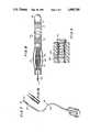
- An insertion toolattaches to the device for insertion into the patient's urethra, inflating the balloons which hold the device in place, thereby inflating the collapsible valve.
- Inflation passages in the insertion toolcommunicate with the device via self-sealing valves, or septums.
- the insertion toolis withdrawn from the urethra, leaving the device in place.
- the self-sealing valvesprevent deflation of the balloons and valve upon withdrawal of the insertion tool.
- the deviceis removable from the urethra generally by means of a cystoscope or similar device.
- a plug at the distal end of the deviceis grasped by the withdrawal tool and pulled, allowing deflation of the balloons and collapsible valve and providing a means for withdrawing the device from the urethra.
- a monofilament cord, or similar devicemay be attached to the plug and allowed to extend outside the urethra to be grasped and pulled to deflate the balloons and valve and facilitate removal of the device.
- FIG. 3is a cross-section of the device taken along lines 3--3 in FIG. 2.
- FIG. 4is a cross-section of the device taken along lines 4--4 in FIG. 2.
- FIG. 5is a cross-section of the device taken along lines 5--5 in FIG. 2.
- FIG. 8is a view of the device as sectioned along its longitudinal axis showing the plug removed and the balloons and valve in deflated conditions.
- FIG. 1illustrates one embodiment of a device 10 of the present invention positioned within the male urethra 17.
- Inflatable balloons 11 and 12located within the bladder 13 and the proximal urethra, respectively, anchor the device 10 in place and secure it against significant movement in either direction.
- a valve assembly 15is located below inflatable balloon 12 and, when inflated, obstructs the urinary passage 21 (shown in FIG. 2) within the device 10 to prevent the flow of urine from the bladder 13.
- a preferred embodiment of device 10generally comprises a tubular body 20 with a longitudinal passageway, or lumen, 21 therein.
- Inflatable balloons 11 and 12serve to anchor the device 10 within the bladder and urethra and valve assembly 15 controls the flow of urine through passageway 21.
- Tubular body 20is preferably formed of a flexible material, for example, silicone, to facilitate insertion and removal of the device as well as to decrease the discomfort normally associated with the use of such a device.
- the materialshould preferably be biocompatible so as not to cause complications within the urinary tract.
- the diameter of tubular body 20is very restricted so that it will easily pass through restricted regions of the urethra.
- tubular body 20contains a passageway, or lumen, 21 extending longitudinally the length of device 10.
- Balloon 12Spaced longitudinally from balloon 11 is fixation balloon 12.
- Balloon 12is formed in a manner similar to that of balloon 11 and is affixed in like manner to the exterior of body 20 at points W and Z, thus forming a second circumferential barrier, or cuff.
- a third longitudinal passageway 32Contained within tubular body 20 and in communication with port 19 is a third longitudinal passageway 32, which will be more fully explained below.
- Sheath 33is pre-formed in a shape resembling an ellipse so that its diameter at its central region is greater than its diameter at either end. This is most easily seen in FIGS. 2 and 8.
- the sheath 33forms an annular space about the body 20 which is typically larger in cross-sectional flow area than the annular space defined when the sheath 33 is collapsed against the body 20, as when passing through areas of restricted diameter.
- the body 20is substantially oval-shaped in its cross-section and contains passages 31, 32, and 35.
- Flow control mechanism 38is located within tubular body 20 at its proximal end.
- the mechanism 38comprises two primary elements.
- a check valve 39is connected at one end to balloon-filling passage 31 and at its other end to valve control passage 35.
- Check valve 39allows one-way flow of fluid from passage 35 into passage 31 but will not allow fluid to flow from passage 31 to passage 35.
- Bleed-back device 40is connected to passages 31 and 35 and is connected in parallel to check valve 39.
- Bleed-back device 40as used in one embodiment, is illustrated in FIG. 6 as a screw 43 loosely threaded into port 44. Threads 46 in port 44 generally provide a loose fit with threads 45 on screw 43, resulting in a helical flow path from passage 31 to passage 35. The operation of flow control mechanism 38 will be explained in detail below.
- devices 10may be substantially as follows:
- device 10Prior to insertion into the urethra, device 10, representing a preferred embodiment of the present invention, is in a completely deflated state. Balloons 11 and 12 and bulb 34 are collapsed against the exterior of body 20. Sheath 33 is in its normal shape, bulged away from body 20. Plug 25 is inserted into chamber 22, obstructing vents 23 and 24, and passageway 35, preventing flow of fluid therebetween.
- Insertion tool 50is attached to the distal end 28 of device 10. Needles 51 and 52 penetrate self-sealing valves 29 and 30, and sleeve 55 on the distal end 28 of device 10 fits snugly around the proximal end 55 of insertion tool 50. Insertion tool 50 is generally in the configuration of a Foley-type catheter, with certain important modifications, and is made of a flexible material such as that used in device 10. Although the Foley-type catheter is generally known to those skilled in the art, the tool 50 departs from construction of the typical Foley-type catheter in certain important ways, particularly in the arrangement of the proximal end 55.
- sheath 33is resistively expandable, it will begin to expand as bulb 34 expands under pressure from the inflation fluid. However, the sheath 33 offers resistance to or bias against continued expansion of bulb 34, creating an effective seal within the annular space between bulb 34 and sheat 33. By varying the volume of inflation fluid injected through self-sealing valve 29, the effectiveness of the seal between sheath 33 and bulb 34 can be varied.
Landscapes
- Health & Medical Sciences (AREA)
- Life Sciences & Earth Sciences (AREA)
- Heart & Thoracic Surgery (AREA)
- Animal Behavior & Ethology (AREA)
- Veterinary Medicine (AREA)
- Public Health (AREA)
- Engineering & Computer Science (AREA)
- Biomedical Technology (AREA)
- General Health & Medical Sciences (AREA)
- Anesthesiology (AREA)
- Hematology (AREA)
- Pulmonology (AREA)
- Biophysics (AREA)
- Urology & Nephrology (AREA)
- Cardiology (AREA)
- Oral & Maxillofacial Surgery (AREA)
- Transplantation (AREA)
- Vascular Medicine (AREA)
- Child & Adolescent Psychology (AREA)
- External Artificial Organs (AREA)
- Media Introduction/Drainage Providing Device (AREA)
Abstract
Description
Claims (11)
Priority Applications (1)
| Application Number | Priority Date | Filing Date | Title |
|---|---|---|---|
| US07/267,748US4909785A (en) | 1986-03-25 | 1988-11-02 | Method for valving body fluids |
Applications Claiming Priority (2)
| Application Number | Priority Date | Filing Date | Title |
|---|---|---|---|
| US84374786A | 1986-03-25 | 1986-03-25 | |
| US07/267,748US4909785A (en) | 1986-03-25 | 1988-11-02 | Method for valving body fluids |
Related Parent Applications (1)
| Application Number | Title | Priority Date | Filing Date |
|---|---|---|---|
| US84374786AContinuation | 1986-03-25 | 1986-03-25 |
Related Child Applications (1)
| Application Number | Title | Priority Date | Filing Date |
|---|---|---|---|
| US07/457,423ContinuationUS5112306A (en) | 1986-03-25 | 1989-12-27 | Method and apparatus for valving body fluids |
Publications (1)
| Publication Number | Publication Date |
|---|---|
| US4909785Atrue US4909785A (en) | 1990-03-20 |
Family
ID=26952609
Family Applications (1)
| Application Number | Title | Priority Date | Filing Date |
|---|---|---|---|
| US07/267,748Expired - LifetimeUS4909785A (en) | 1986-03-25 | 1988-11-02 | Method for valving body fluids |
Country Status (1)
| Country | Link |
|---|---|
| US (1) | US4909785A (en) |
Cited By (75)
| Publication number | Priority date | Publication date | Assignee | Title |
|---|---|---|---|---|
| FR2646610A1 (en)* | 1989-05-05 | 1990-11-09 | Bristol Myers Squibb Co | URETRAL CATHETER HAS REMAINED AND EQUIPPED WITH A SYSTEM FOR CONTROLLING INCONTINENCE AND METHOD OF USING SUCH CATHETER AND SYSTEM |
| US5082006A (en)* | 1987-09-15 | 1992-01-21 | Linda Jonasson | Device for preventing involuntary micturition |
| US5419763A (en)* | 1994-01-04 | 1995-05-30 | Cortrak Medical, Inc. | Prostatic drug-delivery catheter |
| US5624374A (en)* | 1994-11-03 | 1997-04-29 | Von Iderstein; Irwin F. | Involuntary urine control apparatus, system and method |
| WO1998005267A1 (en)* | 1996-08-08 | 1998-02-12 | Cohen Kenneth L | Apparatus for treating incontinence in females |
| US5795288A (en)* | 1996-08-08 | 1998-08-18 | Cohen; Kenneth L. | Apparatus with valve for treating incontinence |
| US5964732A (en)* | 1997-02-07 | 1999-10-12 | Abbeymoor Medical, Inc. | Urethral apparatus with position indicator and methods of use thereof |
| US5971967A (en)* | 1997-08-19 | 1999-10-26 | Abbeymoor Medical, Inc. | Urethral device with anchoring system |
| US6105580A (en)* | 1994-11-03 | 2000-08-22 | Uroscientific, Incorporated | Urine control device |
| WO2001026581A1 (en)* | 1999-10-11 | 2001-04-19 | Uromedica, Inc. | Adjustable implantable genitourinary device |
| WO2002028469A1 (en)* | 2000-10-05 | 2002-04-11 | Muzzammel Mohiuddin M | Uterine balloon catheter |
| US6419701B1 (en) | 1997-06-12 | 2002-07-16 | Uromedica, Inc. | Adjustable implantable genitourinary device |
| US20020107540A1 (en)* | 2001-01-23 | 2002-08-08 | Whalen Mark J. | Endourethral device & method |
| US6527702B2 (en) | 2000-02-01 | 2003-03-04 | Abbeymoor Medical, Inc. | Urinary flow control device and method |
| US20030078467A1 (en)* | 2001-10-18 | 2003-04-24 | Whalen Mark J. | Endourethral device & method |
| US6579230B2 (en)* | 2001-06-15 | 2003-06-17 | Impetus Ltd. | Penile prosthesis and method of implantation |
| US6579224B1 (en) | 1999-10-11 | 2003-06-17 | Uromedica, Inc. | Apparatus and method for inserting an adjustable implantable genitourinary device |
| US6638253B2 (en)* | 2001-07-17 | 2003-10-28 | Eugene Michael Breznock | Method and apparatus for chest drainage |
| US20030208183A1 (en)* | 2000-08-07 | 2003-11-06 | Whalen Mark J. | Endourethral device & method |
| US6645138B2 (en) | 1997-09-12 | 2003-11-11 | Uromedica, Inc. | Adjustable implantable genitourinary device |
| US20040044307A1 (en)* | 2000-10-05 | 2004-03-04 | Richardson Margaret P. | Urinary catheters |
| US20040087995A1 (en)* | 2002-08-22 | 2004-05-06 | Copa Vincent G. | Anastomosis device and related methods |
| WO2004087013A1 (en)* | 2003-03-25 | 2004-10-14 | Scimed Life Systems, Inc. | Retaining stent |
| US6893430B2 (en) | 1998-02-04 | 2005-05-17 | Wit Ip Corporation | Urethral catheter and guide |
| US20050256364A1 (en)* | 1997-06-12 | 2005-11-17 | Uromedica, Inc. | Implantable device and method for adjustably restricting a body lumen |
| US20060079838A1 (en)* | 2004-10-08 | 2006-04-13 | Walker Steven C | Movable Balloon anchor for medical devices |
| US20060079845A1 (en)* | 2004-10-08 | 2006-04-13 | Eben Howard And Pamela A. Howard | Movable inflatable anchor for medical devices |
| US7048698B2 (en) | 2001-06-22 | 2006-05-23 | Abbeymoor Medical, Inc. | Urethral profiling device and methodology |
| US20060116661A1 (en)* | 2002-12-20 | 2006-06-01 | Allan Tanghoej | Device for opening a human bladder |
| US20060241339A1 (en)* | 2005-02-23 | 2006-10-26 | Cook Timothy C | Method and apparatus for an adjustable implantable continence device |
| US20060264985A1 (en)* | 2005-05-20 | 2006-11-23 | Copa Vincent G | Anastomosis device approximating structure configurations |
| US20060276811A1 (en)* | 2005-05-20 | 2006-12-07 | Copa Vincent G | Anastomosis device configurations and methods |
| US20080009793A1 (en)* | 2005-04-21 | 2008-01-10 | Dabbs Clifton R | Foley Catheter Adaptor |
| US20080097493A1 (en)* | 2006-10-17 | 2008-04-24 | Copa Vincent G | Anastomosis Device Having Improved Safety Features |
| US20080114203A1 (en)* | 2006-11-09 | 2008-05-15 | Crank Justin M | Orientation Adapter for Injection Tube in Flexible Endoscope |
| US20080119784A1 (en)* | 2006-11-17 | 2008-05-22 | Suranjan Roychowdhury | Systems, Apparatus and Associated Methods for Needleless Delivery of Therapeutic Fluids |
| US20080140098A1 (en)* | 2006-11-15 | 2008-06-12 | Monica Kumar | Anastomosis Balloon Configurations and device |
| US7390324B2 (en) | 1999-12-01 | 2008-06-24 | Abbeymoor Medical, Inc. | Magnetic retrieval device and method of use |
| US7395822B1 (en) | 1999-04-30 | 2008-07-08 | Uromedica, Inc. | Method and apparatus for adjustable sling for treatment of urinary stress incontinence |
| US20080167526A1 (en)* | 2007-01-08 | 2008-07-10 | Crank Justin M | Non-Occlusive, Laterally-Constrained Injection Device |
| US20080200935A1 (en)* | 2006-11-14 | 2008-08-21 | Hamel Kory P | Anastomosis Device and Method |
| US20090012350A1 (en)* | 2007-07-06 | 2009-01-08 | Claude Tihon | Partial cuff |
| WO2009094015A1 (en)* | 2008-01-22 | 2009-07-30 | Claude Tihon | Partial cuff |
| US20100030139A1 (en)* | 2008-07-30 | 2010-02-04 | Copa Vincent G | Anastomosis Devices and Methods Utilizing Colored Bands |
| US20100081990A1 (en)* | 2008-09-30 | 2010-04-01 | Tyco Healthcare Group Lp | Medical device having prefilled ballon |
| US20100178643A1 (en)* | 2009-01-14 | 2010-07-15 | Lund Jonathan J | Anastomosis deployment force training tool |
| US20100261951A1 (en)* | 2004-02-23 | 2010-10-14 | Uromedica, Inc. | Method and apparatus for an adjustable implantable continence device |
| US20100312226A1 (en)* | 2009-06-03 | 2010-12-09 | John Anderson Armistead | Barb-ended, self-actuating, partially indwelling and continually retained urinary catheter |
| US7850649B2 (en) | 2007-11-09 | 2010-12-14 | Ams Research Corporation | Mechanical volume control for injection devices |
| US20110118767A1 (en)* | 2008-07-30 | 2011-05-19 | Ams Research Corporation | Method and Apparatus for Determining Status of Approximation Structures on Anastomosis Device |
| US8636756B2 (en) | 2005-02-18 | 2014-01-28 | Ams Research Corporation | Anastomosis device and surgical tool actuation mechanism configurations |
| US8747386B2 (en) | 2010-12-16 | 2014-06-10 | Ams Research Corporation | Anastomosis device and related methods |
| US8764775B2 (en) | 2002-08-22 | 2014-07-01 | Ams Research Corporation | Anastomosis device and related methods |
| US20150230904A1 (en)* | 2012-08-12 | 2015-08-20 | Uricon Ltd | Girth Device And Method For Controlling Urinary Incontinence |
| US20160089224A1 (en)* | 2014-09-30 | 2016-03-31 | Coloplast A/S | Urethra clamp |
| US9307991B2 (en) | 2002-08-22 | 2016-04-12 | Ams Research, Llc | Anastomosis device and related methods |
| US9308088B2 (en) | 2011-08-08 | 2016-04-12 | Coloplast A/S | Artificial urinary sphincter system deflation assembly |
| US9375301B2 (en) | 2013-06-06 | 2016-06-28 | Coloplast A/S | Artificial urinary sphincter having a multi-compartment cuff |
| US9381335B2 (en) | 2012-03-21 | 2016-07-05 | Ams Research Corporation | Bladder wall drug delivery system |
| US9440043B2 (en)* | 2014-06-13 | 2016-09-13 | Leading Age Supplies LLC | Catheter having a tapered structure and balloon formed above a lower drainage hole |
| US9486301B2 (en) | 2013-06-21 | 2016-11-08 | Coloplast A/S | Artificial urinary sphincter system having a cuff with an inflatable balloon attached to a frame |
| US20170106175A1 (en)* | 2006-05-18 | 2017-04-20 | Cannuflow, Inc. | Anti-Extravasation Surgical Portal Plug |
| US9717578B2 (en) | 2014-06-12 | 2017-08-01 | Coloplast A/S | Surgical tool adapted for identifying an incision site |
| US9717443B2 (en) | 2014-06-12 | 2017-08-01 | Coloplast A/S | Surgical tool and method for identifying an incision site |
| US9724182B2 (en) | 2014-10-17 | 2017-08-08 | Coloplast A/S | Connector cuff |
| US9744015B2 (en) | 2014-11-17 | 2017-08-29 | Coloplast A/S | Urethra cuff including tube |
| US9814554B2 (en) | 2013-06-06 | 2017-11-14 | Coloplast A/S | Artificial urinary sphincter system |
| US9877817B2 (en) | 2014-05-22 | 2018-01-30 | Coloplast A/S | Surgical tool and system adapted to place a cuff of an artificial urinary sphincter around a portion of a urethra |
| CN109173018A (en)* | 2018-09-19 | 2019-01-11 | 陶崇林 | The adapter of catheter |
| US10219808B2 (en) | 2007-07-06 | 2019-03-05 | Claude Tihon | Partial cuff |
| US10226317B2 (en) | 2013-07-19 | 2019-03-12 | Coloplast A/S | One-piece monolithic cuff and artificial urinary sphincter system |
| CN110719796A (en)* | 2017-04-10 | 2020-01-21 | 医盟科技股份有限公司 | Catheter for draining body fluids |
| US10765520B2 (en) | 2017-04-05 | 2020-09-08 | Coloplast A/S | Penile implant with a length-adjustable tube |
| US11311403B2 (en) | 2019-12-02 | 2022-04-26 | Brian Elder | Erectile dysfunction device and method |
| US11510766B2 (en) | 2019-02-14 | 2022-11-29 | Uromedica, Inc. | Method and apparatus for monitoring implantable device for urinary continence |
Citations (54)
| Publication number | Priority date | Publication date | Assignee | Title |
|---|---|---|---|---|
| GB273951A (en)* | 1926-11-22 | 1927-07-14 | Paul Dietrich | Tubular insertion with automatic closure for the male urethra |
| US1688795A (en)* | 1926-12-01 | 1928-10-23 | Aas Nils | Teat cannula |
| US2638093A (en)* | 1949-12-20 | 1953-05-12 | Kulick George | Vaginal insert |
| US2642874A (en)* | 1951-06-04 | 1953-06-23 | Wilmer B Keeling | Instrument for treating prostate glands |
| US3094124A (en)* | 1960-06-30 | 1963-06-18 | Davol Rubber Co | Arterial catheter |
| US3154077A (en)* | 1962-06-04 | 1964-10-27 | Joseph P Cannon | Hemostatic device for anal surgery |
| US3181558A (en)* | 1962-11-21 | 1965-05-04 | Straub Martha Hunt | Liquid level control for livestock watering troughs |
| US3331371A (en)* | 1965-03-09 | 1967-07-18 | Prosit Service Corp | Catheter having internal flow valve at distal end thereof |
| US3372695A (en)* | 1965-04-27 | 1968-03-12 | Prosit Service Corp | Method of overcoming incontinence |
| US3379197A (en)* | 1965-08-10 | 1968-04-23 | Goodrich Co B F | Self-inflating catheter with means to prevent leakage of inflation fluid |
| US3419008A (en)* | 1966-02-24 | 1968-12-31 | Paul J. Plishner | Magnetically actuated valve clamp for urethra control |
| US3495620A (en)* | 1967-02-09 | 1970-02-17 | Weck & Co Inc Edward | Magnetic valve |
| US3503400A (en)* | 1967-07-12 | 1970-03-31 | Sven M Osthagen | Urethral valve |
| US3575158A (en)* | 1969-07-18 | 1971-04-20 | Fairchild Hiller Corp | Method of controlling urine flow from the bladder with an inplantable pump |
| US3642004A (en)* | 1970-01-05 | 1972-02-15 | Life Support Equipment Corp | Urethral valve |
| US3731670A (en)* | 1971-05-03 | 1973-05-08 | David Roy Pressman | Corporeal fluid control using bistable magnetic duct valve |
| US3750194A (en)* | 1971-03-16 | 1973-08-07 | Fairchild Industries | Apparatus and method for reversibly closing a natural or implanted body passage |
| US3768102A (en)* | 1972-02-03 | 1973-10-30 | Univ Utah | Implantable artificial urethral valve |
| US3769981A (en)* | 1972-02-09 | 1973-11-06 | Kendall & Co | Urinary catheter |
| US3797478A (en)* | 1972-07-11 | 1974-03-19 | M Walsh | Multi-functional valve for use in the urethra |
| US3805794A (en)* | 1971-03-01 | 1974-04-23 | R Schlesinger | Antegrade-retrograde retention catheter |
| US3810259A (en)* | 1971-01-25 | 1974-05-14 | Fairchild Industries | Implantable urinary control apparatus |
| US3811450A (en)* | 1971-10-25 | 1974-05-21 | P Lord | Catheters |
| US3812841A (en)* | 1972-08-21 | 1974-05-28 | L Isaacson | Urethra magnetic valve structure |
| US3817809A (en)* | 1972-03-20 | 1974-06-18 | Int Paper Co | Bare wire process for making retention catheters |
| US3853122A (en)* | 1973-10-12 | 1974-12-10 | B Strauch | Method and device for achieving a penile erection |
| US3903894A (en)* | 1974-07-26 | 1975-09-09 | Isaac Michael Rosen | Implantable clamp |
| US3926175A (en)* | 1974-06-03 | 1975-12-16 | James H Allen | Implantable valve for medical purposes |
| US3938529A (en)* | 1974-07-22 | 1976-02-17 | Gibbons Robert P | Indwelling ureteral catheter |
| US3939821A (en)* | 1973-11-14 | 1976-02-24 | Altair, Incorporated | Magnetically actuated tube compressing valve |
| US3977408A (en)* | 1974-11-01 | 1976-08-31 | Mackew Allan H | Prosthetic catheter |
| US3981299A (en)* | 1971-03-15 | 1976-09-21 | Harry Elmer Murray | Urethral catheter |
| US3995642A (en)* | 1975-04-03 | 1976-12-07 | Medical Dynamics, Inc. | Method and apparatus for retaining a drain tube within a ureter |
| US4022216A (en)* | 1975-08-11 | 1977-05-10 | Stevens Robert C | Urological catheter |
| US4024855A (en)* | 1974-12-30 | 1977-05-24 | Louis Bucalo | Magnetic filamentary structure and method for using the same |
| US4026298A (en)* | 1975-12-03 | 1977-05-31 | Grausz Investment Co. | Artificial urethra |
| US4056095A (en)* | 1975-04-04 | 1977-11-01 | Agence Nationale De Valorisation De La Recherche (Anvar) | Control device for medical and surgical uses |
| US4062363A (en)* | 1973-10-09 | 1977-12-13 | Bonner F J Jun | Catheter |
| US4102342A (en)* | 1975-12-29 | 1978-07-25 | Taichiro Akiyama | Valved device |
| US4140127A (en)* | 1977-04-08 | 1979-02-20 | The Kendall Company | Catheter assembly |
| US4148319A (en)* | 1976-12-29 | 1979-04-10 | Kasper Richard F | Urinary retention catheter |
| US4155364A (en)* | 1977-11-07 | 1979-05-22 | The Regents Of The University Of California | Urinary catheter |
| US4166468A (en)* | 1977-08-05 | 1979-09-04 | Haynie Louis D | Apparatus for endotracheal and esophageal intubation |
| WO1980001460A1 (en)* | 1979-01-12 | 1980-07-24 | Tesi Ab | Catheter |
| US4225979A (en)* | 1977-11-28 | 1980-10-07 | Pierre Rey | Total or partial ureteral prosthesis |
| US4311659A (en)* | 1976-04-05 | 1982-01-19 | Agence Nationale De Valorisation De La Recherche (Anvar) | Processes for the manufacture of organ prostheses |
| US4350161A (en)* | 1980-05-09 | 1982-09-21 | Davis Jr Richard C | Indwelling urethral catheter and method |
| US4368739A (en)* | 1979-07-18 | 1983-01-18 | Nelson Jr Richard L | Long intestinal catheter |
| US4432757A (en)* | 1980-05-09 | 1984-02-21 | Davis Jr Richard C | Indwelling urethral catheter |
| US4456011A (en)* | 1980-12-22 | 1984-06-26 | Irene Warnecke | Balloon-catheter |
| US4457299A (en)* | 1981-02-06 | 1984-07-03 | Cornwell George H I | Incontinence control devices |
| GB2132091A (en)* | 1982-12-07 | 1984-07-04 | Bard Inc C R | Ureteral stent |
| US4549531A (en)* | 1982-04-26 | 1985-10-29 | Medical Engineering Corporation | Artificial sphincter with inflatable cuff |
| US4553533A (en)* | 1983-11-08 | 1985-11-19 | Leighton Stephen B | Intra-urethral prosthetic sphincter valve |
- 1988
- 1988-11-02USUS07/267,748patent/US4909785A/ennot_activeExpired - Lifetime
Patent Citations (55)
| Publication number | Priority date | Publication date | Assignee | Title |
|---|---|---|---|---|
| GB273951A (en)* | 1926-11-22 | 1927-07-14 | Paul Dietrich | Tubular insertion with automatic closure for the male urethra |
| US1688795A (en)* | 1926-12-01 | 1928-10-23 | Aas Nils | Teat cannula |
| US2638093A (en)* | 1949-12-20 | 1953-05-12 | Kulick George | Vaginal insert |
| US2642874A (en)* | 1951-06-04 | 1953-06-23 | Wilmer B Keeling | Instrument for treating prostate glands |
| US3094124A (en)* | 1960-06-30 | 1963-06-18 | Davol Rubber Co | Arterial catheter |
| US3154077A (en)* | 1962-06-04 | 1964-10-27 | Joseph P Cannon | Hemostatic device for anal surgery |
| US3181558A (en)* | 1962-11-21 | 1965-05-04 | Straub Martha Hunt | Liquid level control for livestock watering troughs |
| US3331371A (en)* | 1965-03-09 | 1967-07-18 | Prosit Service Corp | Catheter having internal flow valve at distal end thereof |
| US3372695A (en)* | 1965-04-27 | 1968-03-12 | Prosit Service Corp | Method of overcoming incontinence |
| US3379197A (en)* | 1965-08-10 | 1968-04-23 | Goodrich Co B F | Self-inflating catheter with means to prevent leakage of inflation fluid |
| US3419008A (en)* | 1966-02-24 | 1968-12-31 | Paul J. Plishner | Magnetically actuated valve clamp for urethra control |
| US3495620A (en)* | 1967-02-09 | 1970-02-17 | Weck & Co Inc Edward | Magnetic valve |
| US3503400A (en)* | 1967-07-12 | 1970-03-31 | Sven M Osthagen | Urethral valve |
| US3575158A (en)* | 1969-07-18 | 1971-04-20 | Fairchild Hiller Corp | Method of controlling urine flow from the bladder with an inplantable pump |
| US3642004A (en)* | 1970-01-05 | 1972-02-15 | Life Support Equipment Corp | Urethral valve |
| US3810259A (en)* | 1971-01-25 | 1974-05-14 | Fairchild Industries | Implantable urinary control apparatus |
| US3805794A (en)* | 1971-03-01 | 1974-04-23 | R Schlesinger | Antegrade-retrograde retention catheter |
| US3981299A (en)* | 1971-03-15 | 1976-09-21 | Harry Elmer Murray | Urethral catheter |
| US3750194A (en)* | 1971-03-16 | 1973-08-07 | Fairchild Industries | Apparatus and method for reversibly closing a natural or implanted body passage |
| US3731670A (en)* | 1971-05-03 | 1973-05-08 | David Roy Pressman | Corporeal fluid control using bistable magnetic duct valve |
| US3811450A (en)* | 1971-10-25 | 1974-05-21 | P Lord | Catheters |
| US3768102A (en)* | 1972-02-03 | 1973-10-30 | Univ Utah | Implantable artificial urethral valve |
| US3769981A (en)* | 1972-02-09 | 1973-11-06 | Kendall & Co | Urinary catheter |
| US3817809A (en)* | 1972-03-20 | 1974-06-18 | Int Paper Co | Bare wire process for making retention catheters |
| US3797478A (en)* | 1972-07-11 | 1974-03-19 | M Walsh | Multi-functional valve for use in the urethra |
| US3812841A (en)* | 1972-08-21 | 1974-05-28 | L Isaacson | Urethra magnetic valve structure |
| US4062363A (en)* | 1973-10-09 | 1977-12-13 | Bonner F J Jun | Catheter |
| US3853122A (en)* | 1973-10-12 | 1974-12-10 | B Strauch | Method and device for achieving a penile erection |
| US3939821A (en)* | 1973-11-14 | 1976-02-24 | Altair, Incorporated | Magnetically actuated tube compressing valve |
| US3926175A (en)* | 1974-06-03 | 1975-12-16 | James H Allen | Implantable valve for medical purposes |
| US3938529A (en)* | 1974-07-22 | 1976-02-17 | Gibbons Robert P | Indwelling ureteral catheter |
| US3903894A (en)* | 1974-07-26 | 1975-09-09 | Isaac Michael Rosen | Implantable clamp |
| US3977408A (en)* | 1974-11-01 | 1976-08-31 | Mackew Allan H | Prosthetic catheter |
| US4024855A (en)* | 1974-12-30 | 1977-05-24 | Louis Bucalo | Magnetic filamentary structure and method for using the same |
| US3995642A (en)* | 1975-04-03 | 1976-12-07 | Medical Dynamics, Inc. | Method and apparatus for retaining a drain tube within a ureter |
| US4056095A (en)* | 1975-04-04 | 1977-11-01 | Agence Nationale De Valorisation De La Recherche (Anvar) | Control device for medical and surgical uses |
| US4022216A (en)* | 1975-08-11 | 1977-05-10 | Stevens Robert C | Urological catheter |
| US4026298A (en)* | 1975-12-03 | 1977-05-31 | Grausz Investment Co. | Artificial urethra |
| US4102342A (en)* | 1975-12-29 | 1978-07-25 | Taichiro Akiyama | Valved device |
| US4497074A (en)* | 1976-04-05 | 1985-02-05 | Agence National De Valorisation De La Recherche (Anvar) | Organ prostheses |
| US4311659A (en)* | 1976-04-05 | 1982-01-19 | Agence Nationale De Valorisation De La Recherche (Anvar) | Processes for the manufacture of organ prostheses |
| US4148319A (en)* | 1976-12-29 | 1979-04-10 | Kasper Richard F | Urinary retention catheter |
| US4140127A (en)* | 1977-04-08 | 1979-02-20 | The Kendall Company | Catheter assembly |
| US4166468A (en)* | 1977-08-05 | 1979-09-04 | Haynie Louis D | Apparatus for endotracheal and esophageal intubation |
| US4155364A (en)* | 1977-11-07 | 1979-05-22 | The Regents Of The University Of California | Urinary catheter |
| US4225979A (en)* | 1977-11-28 | 1980-10-07 | Pierre Rey | Total or partial ureteral prosthesis |
| WO1980001460A1 (en)* | 1979-01-12 | 1980-07-24 | Tesi Ab | Catheter |
| US4368739A (en)* | 1979-07-18 | 1983-01-18 | Nelson Jr Richard L | Long intestinal catheter |
| US4350161A (en)* | 1980-05-09 | 1982-09-21 | Davis Jr Richard C | Indwelling urethral catheter and method |
| US4432757A (en)* | 1980-05-09 | 1984-02-21 | Davis Jr Richard C | Indwelling urethral catheter |
| US4456011A (en)* | 1980-12-22 | 1984-06-26 | Irene Warnecke | Balloon-catheter |
| US4457299A (en)* | 1981-02-06 | 1984-07-03 | Cornwell George H I | Incontinence control devices |
| US4549531A (en)* | 1982-04-26 | 1985-10-29 | Medical Engineering Corporation | Artificial sphincter with inflatable cuff |
| GB2132091A (en)* | 1982-12-07 | 1984-07-04 | Bard Inc C R | Ureteral stent |
| US4553533A (en)* | 1983-11-08 | 1985-11-19 | Leighton Stephen B | Intra-urethral prosthetic sphincter valve |
Non-Patent Citations (26)
| Title |
|---|
| "A Silicon Polyester Prosthesis for Ureteral Replacement", Stern et al., 1973, pp. 370-373, 375. |
| "A Study of Micturition in Patients with Cauda Equina Injury", Scott et al., circa 1973, 5 pages. |
| "An Intra-Urethral Silastic Prosthesis", Agarwal et al., (date unknown), 2 pages. |
| "Tissue Reaction Six to Eight Months After Total Ureter Substitution with a Scurasil Prosthesis in Pigs", Svensen, (date unknown), 6 pages. |
| "Total Replacement of Ureter by a Scurasil Prosthesis in Pigs", Djurhuus et al., (date unknown), 26 pages. |
| A Silicon Polyester Prosthesis for Ureteral Replacement , Stern et al., 1973, pp. 370 373, 375.* |
| A Study of Micturition in Patients with Cauda Equina Injury , Scott et al., circa 1973, 5 pages.* |
| An Intra Urethral Silastic Prosthesis , Agarwal et al., (date unknown), 2 pages.* |
| Article in Hospital Practice entitled "Operant Conditioning in Gastro-Intestinal Dysfunctions", Schuster, 9/74, pp. 135-143. |
| Article in Hospital Practice entitled Operant Conditioning in Gastro Intestinal Dysfunctions , Schuster, 9/74, pp. 135 143.* |
| Article in Urology entitled "Use of Completely Implantable Urethral Catheter in Male Patients with Spinal Cord Injury", Munro & Scott, 11/76, pp. 492-494. |
| Article in Urology entitled Use of Completely Implantable Urethral Catheter in Male Patients with Spinal Cord Injury , Munro & Scott, 11/76, pp. 492 494.* |
| Brochure entitled "Scurasil Artificial Ureter", distributed by Rhodia, Inc., (date unknown), 4 pages. |
| Brochure entitled "Scurasil Urological Prosthesis", unknown distributor, unknown date, 5 pages. |
| Brochure entitled "The Rhone-Poulenc Artificial Ureter", distributed by Rhodia, Inc., (date unknown), 1 page. |
| Brochure entitled Scurasil Artificial Ureter , distributed by Rhodia, Inc., (date unknown), 4 pages.* |
| Brochure entitled Scurasil Urological Prosthesis , unknown distributor, unknown date, 5 pages.* |
| Brochure entitled The Rhone Poulenc Artificial Ureter , distributed by Rhodia, Inc., (date unknown), 1 page.* |
| Investigative Urology, entitled "Experiences with a Silastic Spigot as a Replacement for the Urinary Sphincters in Neurogenic Bladder", Conger et al., 11/72, pp. 194-196, 198. |
| Investigative Urology, entitled Experiences with a Silastic Spigot as a Replacement for the Urinary Sphincters in Neurogenic Bladder , Conger et al., 11/72, pp. 194 196, 198.* |
| Publication of National Technical Service, "Intra-Urethral Prosthetic Sphincter Valve", Leighton, 11/83, 29 pages. |
| Publication of National Technical Service, Intra Urethral Prosthetic Sphincter Valve , Leighton, 11/83, 29 pages.* |
| Tissue Reaction Six to Eight Months After Total Ureter Substitution with a Scurasil Prosthesis in Pigs , Svensen, (date unknown), 6 pages.* |
| Total Replacement of Ureter by a Scurasil Prosthesis in Pigs , Djurhuus et al., (date unknown), 26 pages.* |
| Urology, "A Sound-Catheter", Doroshow, 9/74, pp. 346-347. |
| Urology, A Sound Catheter , Doroshow, 9/74, pp. 346 347.* |
Cited By (130)
| Publication number | Priority date | Publication date | Assignee | Title |
|---|---|---|---|---|
| US5082006A (en)* | 1987-09-15 | 1992-01-21 | Linda Jonasson | Device for preventing involuntary micturition |
| FR2646610A1 (en)* | 1989-05-05 | 1990-11-09 | Bristol Myers Squibb Co | URETRAL CATHETER HAS REMAINED AND EQUIPPED WITH A SYSTEM FOR CONTROLLING INCONTINENCE AND METHOD OF USING SUCH CATHETER AND SYSTEM |
| US5419763A (en)* | 1994-01-04 | 1995-05-30 | Cortrak Medical, Inc. | Prostatic drug-delivery catheter |
| US6027442A (en)* | 1994-11-03 | 2000-02-22 | Uroscientific, Inc. | Urethra control device |
| US5624374A (en)* | 1994-11-03 | 1997-04-29 | Von Iderstein; Irwin F. | Involuntary urine control apparatus, system and method |
| US6105580A (en)* | 1994-11-03 | 2000-08-22 | Uroscientific, Incorporated | Urine control device |
| US5792042A (en)* | 1996-08-08 | 1998-08-11 | Cohen; Kenneth L. | Apparatus for treating incontinence in females |
| US5795288A (en)* | 1996-08-08 | 1998-08-18 | Cohen; Kenneth L. | Apparatus with valve for treating incontinence |
| WO1998005267A1 (en)* | 1996-08-08 | 1998-02-12 | Cohen Kenneth L | Apparatus for treating incontinence in females |
| US6258060B1 (en) | 1997-02-07 | 2001-07-10 | Abbeymoon Medical, Inc. | Urethral apparatus with position indicator and methods of use thereof |
| US5964732A (en)* | 1997-02-07 | 1999-10-12 | Abbeymoor Medical, Inc. | Urethral apparatus with position indicator and methods of use thereof |
| US6419701B1 (en) | 1997-06-12 | 2002-07-16 | Uromedica, Inc. | Adjustable implantable genitourinary device |
| US7364540B1 (en) | 1997-06-12 | 2008-04-29 | Uromedica, Inc. | Implantable device and method for adjustably restricting a body lumen |
| US20080156334A1 (en)* | 1997-06-12 | 2008-07-03 | Uromedica, Inc. | Implantable device and method for adjustably restricting a body lumen |
| US20050027161A1 (en)* | 1997-06-12 | 2005-02-03 | Uromedica, Inc. | Adjustable implantable genitourinary device |
| US7828716B2 (en) | 1997-06-12 | 2010-11-09 | Uromedica, Inc. | Implantable device and method for adjustably restricting a body lumen |
| US20050256364A1 (en)* | 1997-06-12 | 2005-11-17 | Uromedica, Inc. | Implantable device and method for adjustably restricting a body lumen |
| US6221060B1 (en) | 1997-08-19 | 2001-04-24 | Abbeymoor Medical, Inc. | Urethral device with anchoring system |
| US5971967A (en)* | 1997-08-19 | 1999-10-26 | Abbeymoor Medical, Inc. | Urethral device with anchoring system |
| US6645138B2 (en) | 1997-09-12 | 2003-11-11 | Uromedica, Inc. | Adjustable implantable genitourinary device |
| US20050165383A1 (en)* | 1998-02-04 | 2005-07-28 | Uzi Eshel | Urethral catheter and guide |
| US6893430B2 (en) | 1998-02-04 | 2005-05-17 | Wit Ip Corporation | Urethral catheter and guide |
| US7395822B1 (en) | 1999-04-30 | 2008-07-08 | Uromedica, Inc. | Method and apparatus for adjustable sling for treatment of urinary stress incontinence |
| WO2001026581A1 (en)* | 1999-10-11 | 2001-04-19 | Uromedica, Inc. | Adjustable implantable genitourinary device |
| US20110124957A1 (en)* | 1999-10-11 | 2011-05-26 | Uromedica, Inc. | Apparatus and method for inserting an adjustable implantable genitourinary device |
| US20060281964A1 (en)* | 1999-10-11 | 2006-12-14 | Uromedica, Inc. | Apparatus and method for inserting an adjustable implantable genitourinary device |
| US20040015045A1 (en)* | 1999-10-11 | 2004-01-22 | Uromedica, Inc. | Apparatus and method for inserting an adjustable implantable genitourinary device |
| US6419624B1 (en) | 1999-10-11 | 2002-07-16 | Uromedica, Inc. | Apparatus and method for inserting an adjustable implantable genitourinary device |
| US7771346B2 (en) | 1999-10-11 | 2010-08-10 | Uromedica, Inc. | Apparatus and method for inserting an adjustable implantable genitourinary device |
| US7014606B2 (en) | 1999-10-11 | 2006-03-21 | Uromedica, Inc. | Apparatus and method for inserting an adjustable implantable genitourinary device |
| US6579224B1 (en) | 1999-10-11 | 2003-06-17 | Uromedica, Inc. | Apparatus and method for inserting an adjustable implantable genitourinary device |
| US7481762B2 (en) | 1999-10-11 | 2009-01-27 | Uromedica, Inc. | Apparatus and method for inserting an adjustable implantable genitourinary device |
| US20020156342A1 (en)* | 1999-10-11 | 2002-10-24 | Uromedica, Inc. | Apparatus and method for inserting an adjustable implantable genitourinary device |
| US7390324B2 (en) | 1999-12-01 | 2008-06-24 | Abbeymoor Medical, Inc. | Magnetic retrieval device and method of use |
| US20060205997A1 (en)* | 2000-02-01 | 2006-09-14 | Whalen Mark J | Urinary flow control device & method |
| US7803106B2 (en)* | 2000-02-01 | 2010-09-28 | Abbeymoor Medical, Inc. | Urinary flow control device and method |
| US7001327B2 (en) | 2000-02-01 | 2006-02-21 | Abbeymoor Medical, Inc. | Urinary flow control device and method |
| US6527702B2 (en) | 2000-02-01 | 2003-03-04 | Abbeymoor Medical, Inc. | Urinary flow control device and method |
| US7758542B2 (en)* | 2000-08-07 | 2010-07-20 | Abbeymoor Medical, Inc. | Endourethral device and method |
| US20030208183A1 (en)* | 2000-08-07 | 2003-11-06 | Whalen Mark J. | Endourethral device & method |
| US20070078389A1 (en)* | 2000-08-07 | 2007-04-05 | Whalen Mark J | Endourethral device & method |
| US7141038B2 (en) | 2000-08-07 | 2006-11-28 | Abbeymoor Medical, Inc. | Endourethral device and method |
| WO2002028469A1 (en)* | 2000-10-05 | 2002-04-11 | Muzzammel Mohiuddin M | Uterine balloon catheter |
| US20040044307A1 (en)* | 2000-10-05 | 2004-03-04 | Richardson Margaret P. | Urinary catheters |
| US20020107540A1 (en)* | 2001-01-23 | 2002-08-08 | Whalen Mark J. | Endourethral device & method |
| US7108655B2 (en) | 2001-01-23 | 2006-09-19 | Abbeymoor Medical, Inc. | Endourethral device and method |
| US6579230B2 (en)* | 2001-06-15 | 2003-06-17 | Impetus Ltd. | Penile prosthesis and method of implantation |
| US7048698B2 (en) | 2001-06-22 | 2006-05-23 | Abbeymoor Medical, Inc. | Urethral profiling device and methodology |
| US20060206097A1 (en)* | 2001-07-17 | 2006-09-14 | Breznock Eugene M | Method and apparatus for chest drainage |
| US6638253B2 (en)* | 2001-07-17 | 2003-10-28 | Eugene Michael Breznock | Method and apparatus for chest drainage |
| US7695467B2 (en) | 2001-07-17 | 2010-04-13 | Breznock Eugene M | Method and apparatus for chest drainage |
| US20030078467A1 (en)* | 2001-10-18 | 2003-04-24 | Whalen Mark J. | Endourethral device & method |
| US6991596B2 (en) | 2001-10-18 | 2006-01-31 | Abbeymoor Medical, Inc. | Endourethral device and method |
| US8529590B2 (en) | 2002-08-22 | 2013-09-10 | Ams Research Corporation | Anastomosis device and related methods |
| US9307991B2 (en) | 2002-08-22 | 2016-04-12 | Ams Research, Llc | Anastomosis device and related methods |
| US8764775B2 (en) | 2002-08-22 | 2014-07-01 | Ams Research Corporation | Anastomosis device and related methods |
| US8551126B2 (en) | 2002-08-22 | 2013-10-08 | Ams Research Corporation | Anastomosis device and related methods |
| US20040087995A1 (en)* | 2002-08-22 | 2004-05-06 | Copa Vincent G. | Anastomosis device and related methods |
| US20060116661A1 (en)* | 2002-12-20 | 2006-06-01 | Allan Tanghoej | Device for opening a human bladder |
| US7670331B2 (en)* | 2002-12-20 | 2010-03-02 | Coloplast A/S | Device for opening a human bladder |
| WO2004087013A1 (en)* | 2003-03-25 | 2004-10-14 | Scimed Life Systems, Inc. | Retaining stent |
| US20100261951A1 (en)* | 2004-02-23 | 2010-10-14 | Uromedica, Inc. | Method and apparatus for an adjustable implantable continence device |
| US20060079845A1 (en)* | 2004-10-08 | 2006-04-13 | Eben Howard And Pamela A. Howard | Movable inflatable anchor for medical devices |
| US20060079838A1 (en)* | 2004-10-08 | 2006-04-13 | Walker Steven C | Movable Balloon anchor for medical devices |
| US8636756B2 (en) | 2005-02-18 | 2014-01-28 | Ams Research Corporation | Anastomosis device and surgical tool actuation mechanism configurations |
| US20060241339A1 (en)* | 2005-02-23 | 2006-10-26 | Cook Timothy C | Method and apparatus for an adjustable implantable continence device |
| US7766870B2 (en) | 2005-04-21 | 2010-08-03 | The United States Of America As Represented By The Secretary Of The Army | Foley catheter adaptor |
| US20080009793A1 (en)* | 2005-04-21 | 2008-01-10 | Dabbs Clifton R | Foley Catheter Adaptor |
| US20060276811A1 (en)* | 2005-05-20 | 2006-12-07 | Copa Vincent G | Anastomosis device configurations and methods |
| US20100168772A1 (en)* | 2005-05-20 | 2010-07-01 | Copa Vincent G | Anastomosis device configurations and methods |
| US8277467B2 (en) | 2005-05-20 | 2012-10-02 | Ams Research Corporation | Anastomosis device configurations and methods |
| US8425540B2 (en) | 2005-05-20 | 2013-04-23 | Ams Research Corporation | Anastomosis device approximating structure configurations |
| US7771443B2 (en) | 2005-05-20 | 2010-08-10 | Ams Research Corporation | Anastomosis device approximating structure configurations |
| US7717928B2 (en) | 2005-05-20 | 2010-05-18 | Ams Research Corporation | Anastomosis device configurations and methods |
| US20060264985A1 (en)* | 2005-05-20 | 2006-11-23 | Copa Vincent G | Anastomosis device approximating structure configurations |
| US20170106175A1 (en)* | 2006-05-18 | 2017-04-20 | Cannuflow, Inc. | Anti-Extravasation Surgical Portal Plug |
| US20080097493A1 (en)* | 2006-10-17 | 2008-04-24 | Copa Vincent G | Anastomosis Device Having Improved Safety Features |
| US8066725B2 (en) | 2006-10-17 | 2011-11-29 | Ams Research Corporation | Anastomosis device having improved safety features |
| US20080114203A1 (en)* | 2006-11-09 | 2008-05-15 | Crank Justin M | Orientation Adapter for Injection Tube in Flexible Endoscope |
| US7993264B2 (en) | 2006-11-09 | 2011-08-09 | Ams Research Corporation | Orientation adapter for injection tube in flexible endoscope |
| US8663257B2 (en) | 2006-11-14 | 2014-03-04 | Ams Research Corporation | Anastomosis device and method |
| US8277466B2 (en) | 2006-11-14 | 2012-10-02 | Ams Research Corporation | Anastomosis device and method |
| US20080200935A1 (en)* | 2006-11-14 | 2008-08-21 | Hamel Kory P | Anastomosis Device and Method |
| US20080140098A1 (en)* | 2006-11-15 | 2008-06-12 | Monica Kumar | Anastomosis Balloon Configurations and device |
| US20080119784A1 (en)* | 2006-11-17 | 2008-05-22 | Suranjan Roychowdhury | Systems, Apparatus and Associated Methods for Needleless Delivery of Therapeutic Fluids |
| US8491525B2 (en) | 2006-11-17 | 2013-07-23 | Ams Research Corporation | Systems, apparatus and associated methods for needleless delivery of therapeutic fluids |
| US20080167526A1 (en)* | 2007-01-08 | 2008-07-10 | Crank Justin M | Non-Occlusive, Laterally-Constrained Injection Device |
| US9956067B2 (en)* | 2007-07-06 | 2018-05-01 | Claude Tihon | Partial cuff |
| US10219808B2 (en) | 2007-07-06 | 2019-03-05 | Claude Tihon | Partial cuff |
| US10792140B2 (en) | 2007-07-06 | 2020-10-06 | Claude Tihon | Partial cuff |
| US20090012350A1 (en)* | 2007-07-06 | 2009-01-08 | Claude Tihon | Partial cuff |
| US7850649B2 (en) | 2007-11-09 | 2010-12-14 | Ams Research Corporation | Mechanical volume control for injection devices |
| US9706900B2 (en) | 2007-11-19 | 2017-07-18 | Ams Research Corporation | Systems, apparatus and associated methods for needleless delivery of therapeutic fluids |
| WO2009094015A1 (en)* | 2008-01-22 | 2009-07-30 | Claude Tihon | Partial cuff |
| CN101917928A (en)* | 2008-01-22 | 2010-12-15 | 克劳德·吉洪 | partial cuff |
| CN101917928B (en)* | 2008-01-22 | 2013-11-27 | 克劳德·吉洪 | Partial cuff |
| US20110118767A1 (en)* | 2008-07-30 | 2011-05-19 | Ams Research Corporation | Method and Apparatus for Determining Status of Approximation Structures on Anastomosis Device |
| US20100030139A1 (en)* | 2008-07-30 | 2010-02-04 | Copa Vincent G | Anastomosis Devices and Methods Utilizing Colored Bands |
| US20100081990A1 (en)* | 2008-09-30 | 2010-04-01 | Tyco Healthcare Group Lp | Medical device having prefilled ballon |
| US7998113B2 (en) | 2008-09-30 | 2011-08-16 | Tyco Healthcare Group Lp | Medical device having prefilled balloon |
| US8388349B2 (en) | 2009-01-14 | 2013-03-05 | Ams Research Corporation | Anastomosis deployment force training tool |
| US20100178643A1 (en)* | 2009-01-14 | 2010-07-15 | Lund Jonathan J | Anastomosis deployment force training tool |
| US8096986B2 (en)* | 2009-06-03 | 2012-01-17 | John Anderson Armistead | Barb-ended, self-actuating, partially indwelling and continually retained urinary catheter |
| US20100312226A1 (en)* | 2009-06-03 | 2010-12-09 | John Anderson Armistead | Barb-ended, self-actuating, partially indwelling and continually retained urinary catheter |
| US8747386B2 (en) | 2010-12-16 | 2014-06-10 | Ams Research Corporation | Anastomosis device and related methods |
| US9308088B2 (en) | 2011-08-08 | 2016-04-12 | Coloplast A/S | Artificial urinary sphincter system deflation assembly |
| US9381335B2 (en) | 2012-03-21 | 2016-07-05 | Ams Research Corporation | Bladder wall drug delivery system |
| US10028812B2 (en)* | 2012-08-12 | 2018-07-24 | Uricon Ltd | Girth device and method for controlling urinary incontinence |
| US20150230904A1 (en)* | 2012-08-12 | 2015-08-20 | Uricon Ltd | Girth Device And Method For Controlling Urinary Incontinence |
| US9375301B2 (en) | 2013-06-06 | 2016-06-28 | Coloplast A/S | Artificial urinary sphincter having a multi-compartment cuff |
| US9814554B2 (en) | 2013-06-06 | 2017-11-14 | Coloplast A/S | Artificial urinary sphincter system |
| US10426584B2 (en) | 2013-06-06 | 2019-10-01 | Coloplast A/S | Method of treating urinary incontinence by implanting a reservoir around a urethra of the user |
| US9486301B2 (en) | 2013-06-21 | 2016-11-08 | Coloplast A/S | Artificial urinary sphincter system having a cuff with an inflatable balloon attached to a frame |
| US10226317B2 (en) | 2013-07-19 | 2019-03-12 | Coloplast A/S | One-piece monolithic cuff and artificial urinary sphincter system |
| US9877817B2 (en) | 2014-05-22 | 2018-01-30 | Coloplast A/S | Surgical tool and system adapted to place a cuff of an artificial urinary sphincter around a portion of a urethra |
| US9717578B2 (en) | 2014-06-12 | 2017-08-01 | Coloplast A/S | Surgical tool adapted for identifying an incision site |
| US9717443B2 (en) | 2014-06-12 | 2017-08-01 | Coloplast A/S | Surgical tool and method for identifying an incision site |
| US9440043B2 (en)* | 2014-06-13 | 2016-09-13 | Leading Age Supplies LLC | Catheter having a tapered structure and balloon formed above a lower drainage hole |
| US9700396B2 (en)* | 2014-09-30 | 2017-07-11 | Coloplast A/S | Urethra clamp |
| US20160089224A1 (en)* | 2014-09-30 | 2016-03-31 | Coloplast A/S | Urethra clamp |
| US9724182B2 (en) | 2014-10-17 | 2017-08-08 | Coloplast A/S | Connector cuff |
| US9744015B2 (en) | 2014-11-17 | 2017-08-29 | Coloplast A/S | Urethra cuff including tube |
| US10765520B2 (en) | 2017-04-05 | 2020-09-08 | Coloplast A/S | Penile implant with a length-adjustable tube |
| CN110719796A (en)* | 2017-04-10 | 2020-01-21 | 医盟科技股份有限公司 | Catheter for draining body fluids |
| CN110719796B (en)* | 2017-04-10 | 2022-05-24 | 医盟科技股份有限公司 | Catheter for draining body fluids |
| CN109173018A (en)* | 2018-09-19 | 2019-01-11 | 陶崇林 | The adapter of catheter |
| US11510766B2 (en) | 2019-02-14 | 2022-11-29 | Uromedica, Inc. | Method and apparatus for monitoring implantable device for urinary continence |
| US11690704B2 (en) | 2019-02-14 | 2023-07-04 | Uromedica, Inc. | Method and apparatus for monitoring implantable device for urinary continence |
| US11690703B2 (en) | 2019-02-14 | 2023-07-04 | Uromedica, Inc. | Method and apparatus for monitoring implantable device for urinary continence |
| US11311403B2 (en) | 2019-12-02 | 2022-04-26 | Brian Elder | Erectile dysfunction device and method |
Similar Documents
| Publication | Publication Date | Title |
|---|---|---|
| US4909785A (en) | Method for valving body fluids | |
| US5112306A (en) | Method and apparatus for valving body fluids | |
| US6491623B2 (en) | Device for preventing fecal incontinence | |
| US5306226A (en) | Urinary control with inflatable seal and method of using same | |
| US5509427A (en) | Urethral plug assembly having adhesive for enhanced sealing capabilities and method of using said plug assembly | |
| US5887593A (en) | Urinary incontinence device | |
| US5724994A (en) | Fluidly expandable urethral plug assembly which receives fluid from an external source and method for controlling urinary incontinence | |
| US5483976A (en) | Mechanically actuated urethral plug assembly and method for controlling urinary incontinence | |
| US8475435B2 (en) | Partial-length indwelling urinary catheter permitting selective urine discharge | |
| US5090424A (en) | Conformable urethral plug | |
| US6013102A (en) | Device for maintaining urinary continence | |
| US4419985A (en) | Apparatus for reversibly closing a body passage | |
| US20040044307A1 (en) | Urinary catheters | |
| JPH0624550B2 (en) | Implantable sphincter device | |
| JPH03109065A (en) | Built-in type urethrocathetel with incontinence control device | |
| CA2246434A1 (en) | Prostatic tissue expander | |
| JP2006528012A (en) | Natural or colostomy closure system | |
| EP0265207A1 (en) | Trans-urethral incontinence device | |
| EP0699060A1 (en) | Expandable urethral plug | |
| AU654511B2 (en) | Urinary control with inflatable seal | |
| US6171230B1 (en) | Female incontinence catheter | |
| EP4366658B1 (en) | An improved pump for an artificial sphinchter | |
| WO1996000542A1 (en) | An assembly and method for prevention of urinary incontinence in humans |
Legal Events
| Date | Code | Title | Description |
|---|---|---|---|
| STCF | Information on status: patent grant | Free format text:PATENTED CASE | |
| FPAY | Fee payment | Year of fee payment:4 | |
| FPAY | Fee payment | Year of fee payment:8 | |
| AS | Assignment | Owner name:WPAMS ACQUISITION CORP., NEW YORK Free format text:ASSIGNMENT OF ASSIGNORS INTEREST;ASSIGNOR:AMERICAN MEDICAL SYSTEMS, INC.;REEL/FRAME:010685/0496 Effective date:19980910 Owner name:AMERICAN MEDICAL SYSTEMS, INC., MINNESOTA Free format text:ASSIGNMENT OF ASSIGNORS INTEREST;ASSIGNOR:WPAMS ACQUISITION CORP.;REEL/FRAME:010685/0505 Effective date:19980702 | |
| AS | Assignment | Owner name:BANK OF AMERICA, N.A., AS AGENT, NORTH CAROLINA Free format text:NOTICE OF GRANT OF SECURITY INTEREST;ASSIGNOR:AMERICAN MEDICAL SYSTEMS, INC., F/K/A WPAMS ACQUISITION CORP.;REEL/FRAME:010795/0619 Effective date:20000417 | |
| FEPP | Fee payment procedure | Free format text:PAYOR NUMBER ASSIGNED (ORIGINAL EVENT CODE: ASPN); ENTITY STATUS OF PATENT OWNER: LARGE ENTITY | |
| FPAY | Fee payment | Year of fee payment:12 | |
| AS | Assignment | Owner name:BANK OF AMERICA, N.A., AS AGENT, NORTH CAROLINA Free format text:NOTICE OF GRANT OF SECURITY INTERST;ASSIGNOR:AMERICAN MEDICAL SYSTEMS, INC.;REEL/FRAME:014186/0257 Effective date:20000417 | |
| AS | Assignment | Owner name:AMERICAN MEDICAL SYSTEMS, INC., MINNESOTA Free format text:SECURITY INTEREST RELEASE;ASSIGNOR:BANK OF AMERICA, N.A.;REEL/FRAME:015596/0795 Effective date:20040701 | |
| AS | Assignment | Owner name:AMERICAN MEDICAL SYSTEMS, INC., MINNESOTA Free format text:RELEASE BY SECURED PARTY;ASSIGNOR:BANK OF AMERICA, N.A., AS AGENT;REEL/FRAME:017846/0709 Effective date:20060628 | |
| AS | Assignment | Owner name:AMERICAN MEDICAL SYSTEMS, INC. F/K/A WPAMS ACQUISI Free format text:RELEASE OF SECURITY INTEREST (SUPERCEDING RELEASE RECORDED ON JULY 30, 2004, AT REEL 015596, FRAME 0795).;ASSIGNOR:BANK OF AMERICA, N.A., AS AGENT;REEL/FRAME:017971/0028 Effective date:20060719 | |
| AS | Assignment | Owner name:AMS RESEARCH CORPORATION, MINNESOTA Free format text:ASSIGNMENT OF ASSIGNORS INTEREST;ASSIGNOR:AMERICAN MEDICAL SYSTEMS, INC.;REEL/FRAME:017971/0777 Effective date:20060718 | |
| AS | Assignment | Owner name:AEMRICAN MEDICAL SYSTEMS, INC., MINNESOTA Free format text:RELEASE OF SECURITY INTEREST (SUPERCEEDING RELEASE RECORDED AT REEL/FRAME 017846/0709);ASSIGNOR:BANK OF AMERICA, N.A., AS AGENT;REEL/FRAME:018109/0700 Effective date:20060717 | |
| AS | Assignment | Owner name:CIT HEALTHCARE LLC, NEW YORK Free format text:SECURITY AGREEMENT;ASSIGNOR:AMERICAN MEDICAL SYSTEMS, INC.;REEL/FRAME:018132/0639 Effective date:20060720 | |
| AS | Assignment | Owner name:AMERICAN MEDICAL SYSTEMS, INC., MINNESOTA Free format text:RELEASE BY SECURED PARTY;ASSIGNOR:CIT HEALTHCARE LLC;REEL/FRAME:026142/0569 Effective date:20110412 |