US4908747A - Advanced proportional plus integral plus derivative controller - Google Patents
Advanced proportional plus integral plus derivative controllerDownload PDFInfo
- Publication number
- US4908747A US4908747AUS07/170,509US17050988AUS4908747AUS 4908747 AUS4908747 AUS 4908747AUS 17050988 AUS17050988 AUS 17050988AUS 4908747 AUS4908747 AUS 4908747A
- Authority
- US
- United States
- Prior art keywords
- signal
- algorithm
- process variable
- proportional
- variable signal
- Prior art date
- Legal status (The legal status is an assumption and is not a legal conclusion. Google has not performed a legal analysis and makes no representation as to the accuracy of the status listed.)
- Expired - Lifetime
Links
Images


Classifications
- G—PHYSICS
- G05—CONTROLLING; REGULATING
- G05B—CONTROL OR REGULATING SYSTEMS IN GENERAL; FUNCTIONAL ELEMENTS OF SUCH SYSTEMS; MONITORING OR TESTING ARRANGEMENTS FOR SUCH SYSTEMS OR ELEMENTS
- G05B11/00—Automatic controllers
- G05B11/01—Automatic controllers electric
- G05B11/36—Automatic controllers electric with provision for obtaining particular characteristics, e.g. proportional, integral, differential
- G05B11/42—Automatic controllers electric with provision for obtaining particular characteristics, e.g. proportional, integral, differential for obtaining a characteristic which is both proportional and time-dependent, e.g. P. I., P. I. D.
Definitions
- the present inventionpertains to proportional plus integral plus differential (PID) controllers in general and more particularly to PID controllers whose ability to produce a multiplicity of algorithms is not limited by the hardware utilized.
- PIDproportional plus integral plus differential
- PIDproportional plus integral plus derivative
- Equations 1, 2 and 3are written in positional form.
- the error signalis replaced with a change in the error signal and a change in control effort is calculated according to the standard equations 1, 2 and 3.
- This change in control effortis integrated over time to generate a control effort.
- the velocity type algorithmwill move away from its constraints as soon as the absolute value of the error signal on which it is acting decreases.
- a positional type algorithmwill not move away from its constraints until the sign of the error signal changes.
- Equations 1, 2 and 3are written to apply derivative action to the error signal.
- One popular variant of these algorithmsis to replace the error signal with the process measurement in the derivative calculation. This change results in smoother transition of the process between setpoint values while not adversely effecting disturbance rejection.
- Equation 1is written in a form that calculates the derivative contribution directly. Typically, this calculation is implemented in conjunction with a first order filter operating at a time constant of 10% of the derivative time. Equation 4, shown below, illustrates this implementation of the derivative calculation. This modification is made to minimize the effect of process noise on the control signal: ##EQU2##
- Prior art industrial PID controllersallow a user to select between the various algorithm forms only by selection of actual hardware. Thus, the hardward utilized determines the forms of algorithms available in a controller. Because of this limitation, it has been desirable to develop a PID controller which produces a multiplicity of algorithm forms not limited by the hardware utilized.
- the present inventionsolves the problems associated with the prior art and other problems by providing a general implementation of a proportional plus integral plus derivative controller.
- a controllercan be any one of the controllers, or variations thereof, discussed in the book Distributed Control Systems by Michael P. Lukas, Von-Nostrand Reinhold Co., 1986.
- An algorithm optionallows the selection of a non-interacting type of controller or a classical interacting type of controller.
- a non-interacting type of controllermay be characterized by the property that tuning any of the controller's three modes does not effect the tuning of the remaining modes.
- the classical interacting type of controllerexhibits interaction among the tuning parameters, thus closely resembling the behavior of analog controllers.
- the algorithm optionalso selects an external reset controller. This option is based upon the classical interacting type of algorithm and provides a mechanism for controlling integration external to the PID algorithm. External reset provides a mechanism for coordinating the action of controllers used in combinations such as cascade configurations.
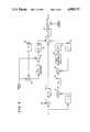
- FIG. 1is a block diagram of a classical interacting type of algorithm.
- FIG. 2is a block diagram of the algorithm shown in FIG. 1 and in the Laplace domain.
- FIG. 3is a block diagram of a non-interacting type of algorithm.
- FIG. 4is a block diagram of the algorithm shown in FIG. 3 and in the Laplace domain.
- FIG. 5is a block diagram of the algorithm illustrated in FIG. 1 and in the reset mode of operation.
- FIG. 1is a block diagram of a classical interacting type of algorithm 10, i.e., the integral term is a function of the proportional term and the derivative term.
- this diagramis comprised of an upper portion which represents the integral term, a middle portion which represents the proportional term, and a lower portion which represents the derivative term.
- a signal representative of the process variable to be controlledis applied to the negative input of a summer 12 having a setpoint signal applied to its positive input.
- the output of the proportional multiplier 14is applied to a positive input to a summer 16.
- the signal representative of the process variableis also applied to the positive input to a summer 18.
- a signal representative of the previous process variableis supplied by a Z transformation function block 20 to the negative input to the summer 18.
- the output of the summer 18is applied to a proportional multiplier 22 which multiplies the incoming signal by the factor kk A .
- the output of the proportional multiplier 22is applied to the positive input to a summer 24 whose other positive input is connected to a Z transformation function block 26 which provides a signal representative of the previous derivative term.
- the output of the summer 24is applied to a proportional multiplier 28 which represents the factor 60k D /60k D +k A ⁇ t).
- the output of the proportional multiplier 28is representative of the derivative term and is applied to a high/low limiter 30 whose output is applied to a negative input to the summer 16.
- the previous algorithmis applied to the negative input to a summer 32 via a Z transformation function block 34 and a switch 36.
- the previous integral termis applied to the positive input to the summer 32 via a Z transformation function block 38.
- the output of the summer 32is applied to a proportional multiplier 40 representative of the function 60/(60+k I ⁇ t) whose output is applied to the positive input to a summer 42.
- the other positive input to the summer 42is connected to the switch 36.
- the output of the summer 42represents the integral term and is applied to a high/low limiter 44 whose output is connected to a positive input to the summer 16.
- the output of the summer 16is applied to a high/low limiter 46 whose output is connected to the positive input to a summer 48 whose other positive input receives a feed forward signal.
- the output of the summer 48is the classical interacting type of proportional plus integral plus derivative algorithm.
- FIG. 2there is illustrated a block diagram of the algorithm shown in FIG. 1 and in the Laplace domain. Those elements which are similar to those shown in FIG. 1 have the same reference numerals and will not be discussed further.
- the elements which produce the derivative term of FIG. 1have been replaced by proportional multipliers 50 and 52 representative of the functions 60kk d S and 1/(60k d s+1), respectively.
- the elements which produce the integral termhave been replaced by a proportional multiplier 54 representive of the function 60k i /S.
- the output of the summer 32is shown as CO which represents the control output.
- FIG. 3A block diagram of a non-interacting type of algorithm 60 is shown in FIG. 3.
- the upper portion, which produces the integral termis comprised of different components.
- the output of the summer 12which represents the error signal, is applied to the proportional multiplier 14 and to a proportional multiplier 62, which represents the function kk I ⁇ t/60, and whose output is applied to the positive input to a summer 64.
- the previous integral termis applied to another positive input to the summer 64 via a Z transformation function block 66.
- the output of the summer 64is applied to the input to a high/low limiter 68 whose output is connected to the positive input to the summer 16.
- the output of the summer 16which represents the proportional plus integral plus derivative algorithm, is applied to the high/low limiter 46 whose output is applied to the summer 48 which produces the control output signal, CO.
- FIG. 4a block diagram of the algorithm shown in FIG. 3 is represented in the Laplace domain.
- This Figurediffers from FIG. 2 in its representation of the upper loop, i.e., the integral term of the algorithm.
- the output of the summer 12is applied to both the proportional multiplier 14 and to a proportional multiplier 68 representative of the function kk i /S.
- the output of the proportional multiplier 68is applied to a positive input to the summer 16 which produces the CO control signal.
- FIG. 5is a block diagram of the algorithm 10 shown in FIG. 1 wherein the switch 36 is in the manual reset position.
- the switch 36is placed in the external reset position.
- Z transformation function block 34is bypassed.
- this Figurediffers from FIG. 1 only with respect to the upper portion thereof, i.e., the portion producing the integral term of the algorithm.
- the algorithm resulting from switch 36 being in the reset positionis used to calculate the output of the feed forward and the algorithm when the algorithm specification is set to 2.
- a selection of 0causes the PID output to be calculated using a classical interacting algorithm, as shown in FIGS. 1 and 2.
- This algorithmis interacting in the sense that tuning any one of the proportional, integral or derivative terms changes the effective value of the other terms.
- a selection of 1causes the PID output to be calculated using a non-interacting control algorithm, as shown in FIGS. 3 and 4.
- tuning the proportional, integral, or derivative termindividually has no effect on the other terms.
- a selection of 2causes the PID output to be calculated using the classical interacting algorithm, as shown in FIG. 1, however, for this selection, the integral term is calculated as a function of the external reset signal, as shown in FIG. 5.
- a selection of 3causes the PID output to be calculated from the proportional and derivative terms only.
Landscapes
- Physics & Mathematics (AREA)
- General Physics & Mathematics (AREA)
- Engineering & Computer Science (AREA)
- Automation & Control Theory (AREA)
- Feedback Control In General (AREA)
Abstract
Description
Claims (9)
Priority Applications (13)
| Application Number | Priority Date | Filing Date | Title |
|---|---|---|---|
| US07/170,509US4908747A (en) | 1988-03-21 | 1988-03-21 | Advanced proportional plus integral plus derivative controller |
| AU22057/88AAU613401B2 (en) | 1988-03-21 | 1988-09-09 | Advanced pid controller |
| IN786/CAL/88AIN171701B (en) | 1988-03-21 | 1988-09-19 | |
| CN88107156ACN1029263C (en) | 1988-03-21 | 1988-09-20 | Advanced proportional plus integral plus derivative controller |
| KR1019880012191AKR970003872B1 (en) | 1988-03-21 | 1988-09-21 | Proportional-Integral-Derivative Control |
| MX14692AMX164495B (en) | 1988-03-21 | 1989-01-27 | PID CONTROLLER (PROPORTIONAL-INTEGRAL-DERIVATIVE) ADVANCED |
| DE68918885TDE68918885T2 (en) | 1988-03-21 | 1989-02-13 | Device for generating process control signals from process variable signals. |
| ES89301332TES2061970T3 (en) | 1988-03-21 | 1989-02-13 | APPARATUS FOR PRODUCING PROCESS CONTROL SIGNALS FROM PROCESS VARIABLES SIGNALS. |
| EP89301332AEP0334476B1 (en) | 1988-03-21 | 1989-02-13 | Apparatus for producing process control signals from process variable signals |
| CA000592234ACA1335211C (en) | 1988-03-21 | 1989-02-27 | Advanced proportional plus integral plus derivative controller |
| BR898901256ABR8901256A (en) | 1988-03-21 | 1989-03-20 | APPARATUS TO PRODUCE A PROCESS CONTROL SIGNAL FROM A VARIABLE PROCESS SIGNAL |
| JP1067756AJP2632575B2 (en) | 1988-03-21 | 1989-03-22 | Improved proportional-integral-derivative motion controller |
| SG178494ASG178494G (en) | 1988-03-21 | 1994-12-20 | Apparatus for producing process control signals from process variable signals |
Applications Claiming Priority (1)
| Application Number | Priority Date | Filing Date | Title |
|---|---|---|---|
| US07/170,509US4908747A (en) | 1988-03-21 | 1988-03-21 | Advanced proportional plus integral plus derivative controller |
Publications (1)
| Publication Number | Publication Date |
|---|---|
| US4908747Atrue US4908747A (en) | 1990-03-13 |
Family
ID=22620132
Family Applications (1)
| Application Number | Title | Priority Date | Filing Date |
|---|---|---|---|
| US07/170,509Expired - LifetimeUS4908747A (en) | 1988-03-21 | 1988-03-21 | Advanced proportional plus integral plus derivative controller |
Country Status (12)
| Country | Link |
|---|---|
| US (1) | US4908747A (en) |
| EP (1) | EP0334476B1 (en) |
| JP (1) | JP2632575B2 (en) |
| KR (1) | KR970003872B1 (en) |
| CN (1) | CN1029263C (en) |
| AU (1) | AU613401B2 (en) |
| BR (1) | BR8901256A (en) |
| CA (1) | CA1335211C (en) |
| DE (1) | DE68918885T2 (en) |
| ES (1) | ES2061970T3 (en) |
| IN (1) | IN171701B (en) |
| MX (1) | MX164495B (en) |
Cited By (12)
| Publication number | Priority date | Publication date | Assignee | Title |
|---|---|---|---|---|
| US5208744A (en)* | 1990-02-23 | 1993-05-04 | Kabushiki Kaisha Toshiba | Automatic adjustment system for a process controller |
| US5319540A (en)* | 1992-02-12 | 1994-06-07 | Puritan-Bennett Corporation | System and method for controlling a periodically actuated ventilation flow system |
| US5453925A (en)* | 1993-05-28 | 1995-09-26 | Fisher Controls International, Inc. | System and method for automatically tuning a process controller |
| US5481453A (en)* | 1994-08-25 | 1996-01-02 | Corporation De L'ecole Polytechnique | Dual loop PID configuration |
| US5504672A (en)* | 1993-09-10 | 1996-04-02 | Hardiman; Ted L. | Industrial process controller and method of process control |
| US6343235B1 (en)* | 1996-07-24 | 2002-01-29 | Mannesmann Rexroth Ag | PID controller with protection of the integrator against saturation upon a rapid change of the reference variable |
| US20070005045A1 (en)* | 2005-06-30 | 2007-01-04 | Intuitive Surgical Inc. | Indicator for tool state and communication in multi-arm robotic telesurgery |
| US20070219648A1 (en)* | 2003-12-19 | 2007-09-20 | Kabushiki Kaisha Yaskawa Denki | Control Calculation Device |
| US20080029261A1 (en)* | 2006-08-01 | 2008-02-07 | Emerson Process Management Power & Water Solutions, Inc. | Steam Temperature Control Using Integrated Function Block |
| US20100185304A1 (en)* | 2009-01-22 | 2010-07-22 | Khalid El-Rifai | Method and Apparatus for Hybrid Resetting States Proportional-Integral-Derivative and Lag Controllers |
| US8301275B2 (en) | 2010-06-04 | 2012-10-30 | Sti Srl | Modified proportional integral derivative controller |
| CN103116281A (en)* | 2013-01-17 | 2013-05-22 | 江苏大学 | Model-free adaptive control system of axial mixing magnetic bearing and control method thereof |
Families Citing this family (6)
| Publication number | Priority date | Publication date | Assignee | Title |
|---|---|---|---|---|
| JP3164667B2 (en)* | 1992-10-08 | 2001-05-08 | 株式会社東芝 | Adjustment device |
| EP0605214B1 (en)* | 1992-12-28 | 1997-11-19 | Hitachi, Ltd. | High speed low noise current collecting equipment |
| EP4081868A2 (en)* | 2018-11-06 | 2022-11-02 | Valentin DIMAKOV | Adaptive tuning method for a digital pid controller |
| CN113325693B (en)* | 2021-05-25 | 2023-03-24 | 国网新疆电力有限公司电力科学研究院 | Improved PID control method and device for SCR denitration system |
| CN113605997B (en)* | 2021-08-31 | 2023-06-27 | 中国电建集团河南工程有限公司 | Control method for single-loop double-regulation object of turbine bypass system |
| CN115309140A (en)* | 2022-08-31 | 2022-11-08 | 广东电网有限责任公司 | A forward advance observation device and system for process signal |
Citations (4)
| Publication number | Priority date | Publication date | Assignee | Title |
|---|---|---|---|---|
| US4390942A (en)* | 1979-10-19 | 1983-06-28 | Ihc Holland N.V. | Control system |
| US4556956A (en)* | 1983-09-16 | 1985-12-03 | General Electric Company | Adjustable gain controller for valve position control loop and method for reducing jitter |
| US4630187A (en)* | 1985-09-09 | 1986-12-16 | Sperry Corporation | Power converter with duty ratio quantization |
| US4669040A (en)* | 1984-09-19 | 1987-05-26 | Eurotherm Corporation | Self-tuning controller |
Family Cites Families (3)
| Publication number | Priority date | Publication date | Assignee | Title |
|---|---|---|---|---|
| JPS6047001U (en)* | 1983-09-06 | 1985-04-02 | 理化工業株式会社 | Algorithm switching analog controller |
| JPS60163101A (en)* | 1984-02-03 | 1985-08-26 | Nissin Electric Co Ltd | Process controller |
| JPH0746282B2 (en)* | 1987-08-12 | 1995-05-17 | 株式会社日立製作所 | Non-interference control method and apparatus |
- 1988
- 1988-03-21USUS07/170,509patent/US4908747A/ennot_activeExpired - Lifetime
- 1988-09-09AUAU22057/88Apatent/AU613401B2/ennot_activeCeased
- 1988-09-19ININ786/CAL/88Apatent/IN171701B/enunknown
- 1988-09-20CNCN88107156Apatent/CN1029263C/ennot_activeExpired - Fee Related
- 1988-09-21KRKR1019880012191Apatent/KR970003872B1/ennot_activeExpired - Lifetime
- 1989
- 1989-01-27MXMX14692Apatent/MX164495B/enunknown
- 1989-02-13ESES89301332Tpatent/ES2061970T3/ennot_activeExpired - Lifetime
- 1989-02-13DEDE68918885Tpatent/DE68918885T2/ennot_activeExpired - Fee Related
- 1989-02-13EPEP89301332Apatent/EP0334476B1/ennot_activeExpired - Lifetime
- 1989-02-27CACA000592234Apatent/CA1335211C/ennot_activeExpired - Fee Related
- 1989-03-20BRBR898901256Apatent/BR8901256A/enunknown
- 1989-03-22JPJP1067756Apatent/JP2632575B2/ennot_activeExpired - Lifetime
Patent Citations (4)
| Publication number | Priority date | Publication date | Assignee | Title |
|---|---|---|---|---|
| US4390942A (en)* | 1979-10-19 | 1983-06-28 | Ihc Holland N.V. | Control system |
| US4556956A (en)* | 1983-09-16 | 1985-12-03 | General Electric Company | Adjustable gain controller for valve position control loop and method for reducing jitter |
| US4669040A (en)* | 1984-09-19 | 1987-05-26 | Eurotherm Corporation | Self-tuning controller |
| US4630187A (en)* | 1985-09-09 | 1986-12-16 | Sperry Corporation | Power converter with duty ratio quantization |
Cited By (16)
| Publication number | Priority date | Publication date | Assignee | Title |
|---|---|---|---|---|
| US5208744A (en)* | 1990-02-23 | 1993-05-04 | Kabushiki Kaisha Toshiba | Automatic adjustment system for a process controller |
| US5319540A (en)* | 1992-02-12 | 1994-06-07 | Puritan-Bennett Corporation | System and method for controlling a periodically actuated ventilation flow system |
| US5453925A (en)* | 1993-05-28 | 1995-09-26 | Fisher Controls International, Inc. | System and method for automatically tuning a process controller |
| US5504672A (en)* | 1993-09-10 | 1996-04-02 | Hardiman; Ted L. | Industrial process controller and method of process control |
| US5481453A (en)* | 1994-08-25 | 1996-01-02 | Corporation De L'ecole Polytechnique | Dual loop PID configuration |
| US6343235B1 (en)* | 1996-07-24 | 2002-01-29 | Mannesmann Rexroth Ag | PID controller with protection of the integrator against saturation upon a rapid change of the reference variable |
| US7463938B2 (en)* | 2003-12-19 | 2008-12-09 | Kabushiki Kaisha Yaskawa Denki | Control calculation device |
| US20070219648A1 (en)* | 2003-12-19 | 2007-09-20 | Kabushiki Kaisha Yaskawa Denki | Control Calculation Device |
| US20070005045A1 (en)* | 2005-06-30 | 2007-01-04 | Intuitive Surgical Inc. | Indicator for tool state and communication in multi-arm robotic telesurgery |
| US20080029261A1 (en)* | 2006-08-01 | 2008-02-07 | Emerson Process Management Power & Water Solutions, Inc. | Steam Temperature Control Using Integrated Function Block |
| US7668623B2 (en)* | 2006-08-01 | 2010-02-23 | Emerson Process Management Power & Water Solutions, Inc. | Steam temperature control using integrated function block |
| US20100185304A1 (en)* | 2009-01-22 | 2010-07-22 | Khalid El-Rifai | Method and Apparatus for Hybrid Resetting States Proportional-Integral-Derivative and Lag Controllers |
| US8200347B2 (en)* | 2009-01-22 | 2012-06-12 | Mitsubishi Electric Research Laboratories, Inc. | Method and apparatus for hybrid resetting states proportional-integral-derivative and lag controllers |
| US8301275B2 (en) | 2010-06-04 | 2012-10-30 | Sti Srl | Modified proportional integral derivative controller |
| CN103116281A (en)* | 2013-01-17 | 2013-05-22 | 江苏大学 | Model-free adaptive control system of axial mixing magnetic bearing and control method thereof |
| CN103116281B (en)* | 2013-01-17 | 2015-08-05 | 江苏大学 | Axial mixed magnetic bearing MFA control system and control method thereof |
Also Published As
| Publication number | Publication date |
|---|---|
| CN1036086A (en) | 1989-10-04 |
| KR890015095A (en) | 1989-10-28 |
| AU613401B2 (en) | 1991-08-01 |
| CA1335211C (en) | 1995-04-11 |
| JP2632575B2 (en) | 1997-07-23 |
| KR970003872B1 (en) | 1997-03-22 |
| AU2205788A (en) | 1989-09-21 |
| EP0334476A2 (en) | 1989-09-27 |
| DE68918885T2 (en) | 1995-02-23 |
| EP0334476A3 (en) | 1990-07-11 |
| CN1029263C (en) | 1995-07-05 |
| JPH01273101A (en) | 1989-11-01 |
| MX164495B (en) | 1992-08-20 |
| DE68918885D1 (en) | 1994-11-24 |
| IN171701B (en) | 1992-12-19 |
| BR8901256A (en) | 1989-11-07 |
| ES2061970T3 (en) | 1994-12-16 |
| EP0334476B1 (en) | 1994-10-19 |
Similar Documents
| Publication | Publication Date | Title |
|---|---|---|
| US4908747A (en) | Advanced proportional plus integral plus derivative controller | |
| US4995232A (en) | Running control for a gas turbine engine | |
| KR100242447B1 (en) | Method and system for path planning in robot control | |
| CA2057237C (en) | Sliding mode control system | |
| US5695156A (en) | Aircraft vertical position control system | |
| JP2875023B2 (en) | Regulator for especially non-linear time-varying processes | |
| US5093609A (en) | Servomotor control method | |
| JPH0454242B2 (en) | ||
| JPH05150802A (en) | Deviation variable and deviation hysteresis type pi control method | |
| RU2027212C1 (en) | Adaptive non-linear control system | |
| JPS6346503A (en) | PID adjustment device | |
| JPS63257487A (en) | Controlling method for servo-motor | |
| JP2965658B2 (en) | Turbine control method | |
| JPS5593906A (en) | Controller for turbine regulating valve in pressure change operation | |
| SU736046A1 (en) | Variable-structure regulator | |
| JPH0334081B2 (en) | ||
| SU367409A1 (en) | COMBINED NEXT SYSTEM | |
| Meyfarth | Bang-Bang Versus Linear Control of a Second-Order Rate-Type Servomotor | |
| JPS6356562B2 (en) | ||
| JPH05324004A (en) | Time proportional output device | |
| JPH0239202A (en) | Process control circuit | |
| JPS581244B2 (en) | Turbine control device | |
| JPH03164805A (en) | Fuzzy controller | |
| JPH0312202B2 (en) | ||
| Saleh et al. | A new model reference adaptive control law |
Legal Events
| Date | Code | Title | Description |
|---|---|---|---|
| AS | Assignment | Owner name:BABCOCK & WILCOX COMPANY, THE,LOUISIANA Free format text:ASSIGNMENT OF ASSIGNORS INTEREST;ASSIGNORS:MATSKO, THEODORE, N.;PATELLA, JOSEPH, G.;SCHEIB, THOMAS, J.;AND OTHERS;SIGNING DATES FROM 19880310 TO 19880322;REEL/FRAME:004865/0403 Owner name:BABCOCK & WILCOX COMPANY, THE, NEW ORLEANS, LOUISI Free format text:ASSIGNMENT OF ASSIGNORS INTEREST.;ASSIGNORS:MATSKO, THEODORE, N.;PATELLA, JOSEPH, G.;SCHEIB, THOMAS, J.;AND OTHERS;REEL/FRAME:004865/0403;SIGNING DATES FROM 19880310 TO 19880322 | |
| AS | Assignment | Owner name:BABCOCK & WILCOX TRACY POWER, INC., A CORP. OF DE, Free format text:ASSIGNMENT OF ASSIGNORS INTEREST.;ASSIGNOR:BABCOCK & WILCOX COMPANY, THE, A CORP. OF DE;REEL/FRAME:005161/0198 Effective date:19890831 | |
| STCF | Information on status: patent grant | Free format text:PATENTED CASE | |
| AS | Assignment | Owner name:ELSAG INTERNATIONAL B.V., A CORP. OF THE NETHERLAN Free format text:ASSIGNMENT OF ASSIGNORS INTEREST.;ASSIGNOR:BABCOCK & WILCOX TRACY POWER, INC., A CORP. OF DE;REEL/FRAME:005238/0432 Effective date:19891031 | |
| FEPP | Fee payment procedure | Free format text:PAYOR NUMBER ASSIGNED (ORIGINAL EVENT CODE: ASPN); ENTITY STATUS OF PATENT OWNER: LARGE ENTITY | |
| FPAY | Fee payment | Year of fee payment:4 | |
| FEPP | Fee payment procedure | Free format text:PAYER NUMBER DE-ASSIGNED (ORIGINAL EVENT CODE: RMPN); ENTITY STATUS OF PATENT OWNER: LARGE ENTITY Free format text:PAYOR NUMBER ASSIGNED (ORIGINAL EVENT CODE: ASPN); ENTITY STATUS OF PATENT OWNER: LARGE ENTITY | |
| FPAY | Fee payment | Year of fee payment:8 | |
| REMI | Maintenance fee reminder mailed | ||
| FPAY | Fee payment | Year of fee payment:12 | |
| SULP | Surcharge for late payment | Year of fee payment:11 | |
| AS | Assignment | Owner name:ABB TECHNOLOGY LTD., SWITZERLAND Free format text:ASSIGNMENT OF ASSIGNORS INTEREST;ASSIGNOR:ABB INC.;REEL/FRAME:018911/0830 Effective date:20050101 |