US4908523A - Electronic circuit with power drain control - Google Patents
Electronic circuit with power drain controlDownload PDFInfo
- Publication number
- US4908523A US4908523AUS07/176,960US17696088AUS4908523AUS 4908523 AUS4908523 AUS 4908523AUS 17696088 AUS17696088 AUS 17696088AUS 4908523 AUS4908523 AUS 4908523A
- Authority
- US
- United States
- Prior art keywords
- battery
- circuit
- voltage
- microprocessor
- coupled
- Prior art date
- Legal status (The legal status is an assumption and is not a legal conclusion. Google has not performed a legal analysis and makes no representation as to the accuracy of the status listed.)
- Expired - Lifetime
Links
Images

Classifications
- G—PHYSICS
- G06—COMPUTING OR CALCULATING; COUNTING
- G06F—ELECTRIC DIGITAL DATA PROCESSING
- G06F1/00—Details not covered by groups G06F3/00 - G06F13/00 and G06F21/00
- G06F1/26—Power supply means, e.g. regulation thereof
- G06F1/32—Means for saving power
- G06F1/3203—Power management, i.e. event-based initiation of a power-saving mode
- G06F1/3206—Monitoring of events, devices or parameters that trigger a change in power modality
- G06F1/3228—Monitoring task completion, e.g. by use of idle timers, stop commands or wait commands
- G—PHYSICS
- G06—COMPUTING OR CALCULATING; COUNTING
- G06F—ELECTRIC DIGITAL DATA PROCESSING
- G06F1/00—Details not covered by groups G06F3/00 - G06F13/00 and G06F21/00
- G06F1/26—Power supply means, e.g. regulation thereof
- G06F1/30—Means for acting in the event of power-supply failure or interruption, e.g. power-supply fluctuations
- G—PHYSICS
- G08—SIGNALLING
- G08B—SIGNALLING OR CALLING SYSTEMS; ORDER TELEGRAPHS; ALARM SYSTEMS
- G08B3/00—Audible signalling systems; Audible personal calling systems
- G08B3/10—Audible signalling systems; Audible personal calling systems using electric transmission; using electromagnetic transmission
- G08B3/1008—Personal calling arrangements or devices, i.e. paging systems
- G08B3/1016—Personal calling arrangements or devices, i.e. paging systems using wireless transmission
- G08B3/1025—Paging receivers with audible signalling details
- G08B3/1066—Paging receivers with audible signalling details with other provisions not elsewhere provided for, e.g. turn-off protection
- H—ELECTRICITY
- H02—GENERATION; CONVERSION OR DISTRIBUTION OF ELECTRIC POWER
- H02J—CIRCUIT ARRANGEMENTS OR SYSTEMS FOR SUPPLYING OR DISTRIBUTING ELECTRIC POWER; SYSTEMS FOR STORING ELECTRIC ENERGY
- H02J9/00—Circuit arrangements for emergency or stand-by power supply, e.g. for emergency lighting
- H02J9/04—Circuit arrangements for emergency or stand-by power supply, e.g. for emergency lighting in which the distribution system is disconnected from the normal source and connected to a standby source
- H02J9/06—Circuit arrangements for emergency or stand-by power supply, e.g. for emergency lighting in which the distribution system is disconnected from the normal source and connected to a standby source with automatic change-over, e.g. UPS systems
- H02J9/061—Circuit arrangements for emergency or stand-by power supply, e.g. for emergency lighting in which the distribution system is disconnected from the normal source and connected to a standby source with automatic change-over, e.g. UPS systems for DC powered loads
- H—ELECTRICITY
- H04—ELECTRIC COMMUNICATION TECHNIQUE
- H04W—WIRELESS COMMUNICATION NETWORKS
- H04W52/00—Power management, e.g. Transmission Power Control [TPC] or power classes
- H04W52/02—Power saving arrangements
- H04W52/0209—Power saving arrangements in terminal devices
- H04W52/0261—Power saving arrangements in terminal devices managing power supply demand, e.g. depending on battery level
- H04W52/0296—Power saving arrangements in terminal devices managing power supply demand, e.g. depending on battery level switching to a backup power supply
- Y—GENERAL TAGGING OF NEW TECHNOLOGICAL DEVELOPMENTS; GENERAL TAGGING OF CROSS-SECTIONAL TECHNOLOGIES SPANNING OVER SEVERAL SECTIONS OF THE IPC; TECHNICAL SUBJECTS COVERED BY FORMER USPC CROSS-REFERENCE ART COLLECTIONS [XRACs] AND DIGESTS
- Y02—TECHNOLOGIES OR APPLICATIONS FOR MITIGATION OR ADAPTATION AGAINST CLIMATE CHANGE
- Y02D—CLIMATE CHANGE MITIGATION TECHNOLOGIES IN INFORMATION AND COMMUNICATION TECHNOLOGIES [ICT], I.E. INFORMATION AND COMMUNICATION TECHNOLOGIES AIMING AT THE REDUCTION OF THEIR OWN ENERGY USE
- Y02D30/00—Reducing energy consumption in communication networks
- Y02D30/70—Reducing energy consumption in communication networks in wireless communication networks
Definitions
- This inventionrelates to power switching circuit arrangements for supplying power to an electronic circuit.
- the inventionis particularly, although not exclusively applicable, to a radio pager having a micro-computer which requires to be powered continuously from either a relatively high capacity main battery or from a relatively low capacity backup battery.
- the back-up batteryis commonly coupled to the power supply by way of simple isolation diodes or series transistor switches. Both of these switching techniques are relatively inefficient and also the use of isolation diodes is not possible at operating voltages significantly below 2V.
- An object of the inventionis to provide an improved power switching circuit.
- a further object of the inventionis to provide a power switching circuit for controlling the supply of power from either a primary or secondary battery, and which is capable of switching between primary and secondary batteries at voltages below 2V.
- a still further objectis to control battery discharge to provide extended operating life.
- a power switching circuitfor selectively coupling an output terminal to a first or a second battery, the circuit comprising a first input terminal for connection to the first battery; a second input terminal for connection to the second battery; an output terminal; switching means responsive to the voltage of the first battery for selectively switching the output terminal from the first to second input terminal in response to the voltage of the first battery falling to a predetermined level.
- the switching meansmay include a comparator coupled to compare the voltage at the first input terminal with a first reference voltage.
- the comparatormay conveniently be operative to compare the voltage of the first battery with each of a plurality of reference voltages.
- Conveniently warning meansprovides a low battery warning in response to the voltage of the first battery having fallen to the level of a predetermined one of the plurality of reference voltages.
- a second output terminalis provided coupled to the first input terminal through second switching means controllable by the first switching means, to isolate the second output terminal from the first battery in response to the voltage of the first battery having fallen to the level of a further predetermined one of the plurality of reference voltages.
- a first circuit portionwhich is preferably a microprocessor may be coupled to the output terminal of the switching circuit.
- the microprocessormay be operative to provide timekeeping functions and may be coupled to a time of day display.
- the microprocessormay be coupled to the first switching means for receiving an indication of selection of the second input terminal, storage means being coupled to the microprocessor for storing an indication of the duration of connection to the second input terminal.
- the microprocessormay be operative to inhibit power consumption when the said duration exceeds a predetermined duration.
- a second circuit portion typically including relatively high power radio paging circuitsmay be coupled to the second output terminal.
- the switching meanspreferably includes a switched voltage regulator having respective inputs coupled to the said first and second input terminals and an output coupled to the said output terminal, means being provided for supplying switching signals to the regulator.
- a battery compartmentmay be provided for the first battery, the compartment having access means to enable removal of the battery; sensing means being provided for sensing the opening of the access means, the switching means being responsive to an output signal provided in the sensing means to isolate the second circuit portion from the first battery.
- a radio pager and time piecehaving a relatively high power portion and a relatively low power timekeeping portion and a time of day display driven by the timekeeping portion; a power switching circuit having a first input terminal for connection to a first battery; a second input terminal for connection to a second battery; an output terminal coupled to the timekeeping portion; switching means responsive to the voltage of the first battery for selectively switching the output terminal from the first to the second input terminal; in response to the voltage of the first battery falling to a predetermined level.
- an electronic circuithaving a plurality of operating functions and including a power supply terminal connectible to a battery for supplying power to the electronic circuit and means responsive to the battery voltage at the power supply terminal for selecting predetermined ones of said operating functions in dependence upon the battery voltage level.
- a power switching circuitfor selectively coupling an output terminal to a first or a second battery, the circuit comprising a first input terminal for connection to the first battery; a second input terminal for connection to the second battery; an output terminal; switching means for selectively coupling the output terminal to the first or second input terminal; a battery compartment for housing at least the first battery, the compartment having access means to enable removal of the first battery;
- sensing meansfor sensing the opening of the access means and means responsive to an output signal provided by the sensing means for controlling the switching means to select coupling of the output terminal to the second input terminal.
- a voltage switching circuitfor selectively providing an output voltage derived from at least one of a plurality of voltage sources, the circuit comprising; a plurality of input terminals for coupling to respective voltage sources; an output terminal; capacitive means coupled between the output terminal and a ground reference terminal; a plurality of transistors each having a first electrode coupled to a respective one of the input terminals and to the output terminal, a second electrode coupled to the ground reference terminal and a control electrode; pulse width modulator means coupled to the output terminal and switching means for selectively coupling the pulse width modulator means to the control electrode of at least one selected transistor in dependence upon the desired voltage source.
- an electronic circuitconnectible to a battery and comprising a microprocessor operable under program control at a plurality of bus frequencies the bus frequency being selected in dependence upon the battery voltage level.
- FIG. 1illustrates schematically an embodiment of a radio pager including the power switching circuit of the invention.
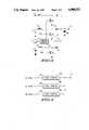
- FIG. 2is a graph illustrating the decay of battery voltage with time.
- FIG. 3illustrates schematically a voltage switching circuit for use in the circuit of FIG. 1,
- FIG. 4illustrates an alternative embodiment of voltage switching circuit.
- the microprocessor 2is coupled to the high power portion 1 by a bus 3.
- the microprocessor 2provides a time signal output to a time of day display 4 and is also coupled to a non-volatile memory 5 which is typically an EEPROM memory.
- Power for the high current circuits 1 and the microprocessor 2is supplied from either a main battery 6 or a backup battery 7.
- the main battery 6is coupled to a first input terminal 9.
- a smoothing capacitor 8is coupled between the terminal 9 and ground.
- a second input terminal 10is connected to the secondary battery 7.
- the second input terminal 10forms one input terminal of a first switch 11, a second input of which is connected to the first input terminal 9.
- the switch 11has its output connected to a first output terminal 12 which is coupled to a power input terminal 13 of the microprocessor 2.
- a power input terminal 14 of the portion 1is coupled via a second switch 15 to the terminal 9 and consequently to the main battery 6.
- the first input terminal 9is also coupled to one input of a comparator 16, a second input of which is coupled to the output terminal 17 of a cyclically scanning switch 18 having three input terminals 19, 20 and 21 for respectively receiving reference voltages V 1 , V 2 and V 3 of which V 1 is the largest, V 2 the next largest and V 3 the smallest.
- the comparator 16has an output bus 22 coupled to a control circuit 23 which has output buses 24, 25, 26, and a two way bus connection 27 to the microprocessor 2.
- the two way bus 27enables the microprocessor to exert overall control of the control circuit 23 based upon programmed battery threshold information.
- the output bus 24is coupled to the control circuit 23 to control the switching of the first switch 11 between the two input terminals 9 and 10 whilst the bus 25 controls the cyclic switching of the switch 18.
- the output bus 26is connected to control the opening and closing of the second switch 15.
- An additional output bus 30(shown dashed) is coupled to the high current circuits 1.
- a warning alarm 28which may be a visual, audible or any other sensible alarm is coupled to the microprocessor 2 via a bus 29.
- the main battery 6is conveniently located in a compartment 31 having a door or other suitable closure 32.
- a door opening sensor 33which may be an optical sensor or a simple switch sensor, is coupled to the control circuit 23 by means of a bus 34.
- the circuit portion 1requires a relatively high level of power to operate and needs to be driven by the main battery.
- the backup battery 7has a relatively small capacity and is unable to drive the high current portion 1 in normal operation.
- the microprocessor 2requires only a relatively low power battery and whilst preferably powered by the main battery 6, may also be powered by the backup battery 7.
- the microprocessor 2in view of its timekeeping function must have some of its functions powered continuously even when the main battery has fallen to a level which is too low adequately to power the high power portion 1 and also when the main battery is removed for replacement.
- the control circuitvia the bus 25 and the switch 18, couples each of the reference voltages 19, 20 and 21, in turn to the reference voltage input terminal 17 of the comparator 6, which compares each reference voltage with that of the main battery 6.
- the portion 1 and the microprocessor 2remain powered by the main battery 6.
- the comparator 16provides an output signal at its output 22 which is fed to the control circuit 23.
- the control circuitprovides over the bus 27 a signal to the microprocessor 2, which in turn provides an output signal on the bus 29, to activate the alarm 28 to provide a warning that the voltage of the main battery is becoming low. Both the high power portion 1 and the microprocessor 2 remain powered by the battery 6.
- the comparatorWhen the voltage of the main battery has fallen to the level of the reference voltage V 2 , the comparator provides another output signal, which is fed to the control circuit 23 which in response provides a signal on the bus 27 to open the switch 15 to isolate the portion 1 from the main battery. The higher power paging circuits are thus turned off.
- the microprocessor 2remains coupled to the main battery 6, which still retains adequate capacity to drive the essential timekeeping functions of the microprocessor 2.
- microprocessor functionsmay also be eliminated as the main battery voltage falls to prolong the useful life of the main battery and postpone switching to the backing battery.
- the microprocessor 2may, under program control, change its operating frequency in response to changing battery voltage. In particular as the battery voltage falls the microprocessor may switch to a lower bus frequency to reduce its power consumption.
- the capacity of the backup battery 7is typically small, it may be necessary to limit the duration of its use to power the microprocessor. In the embodiment of FIG. 1, this is done by the microprocessor 2 measuring the time during which it is coupled to the secondary battery.
- the control circuit 23provides an output signal to the microprocessor 2 over the bus 28 each time that the control circuit 23 effects a change over to the backup battery. This output signal to the microprocessor 2 is used by the microprocessor to initiate a measurement of the time duration by starting a timer of predetermined length.
- the microprocessorWhen the timer has run down the microprocessor shuts down to prevent further power drain from the backup battery.
- the elapsed time spent draining power from the backup batterymay be stored in the EEPROM 5.
- the elapsed timemay be displayed to indicate the remaining usable life of the backup battery. In order to achieve a sufficiently low current state to prolong the life of the backup battery some microprocessor functions may be eliminated whilst powered by the backup battery leaving only the essential timekeeping function.
- the switch 15it is also possible via the additional bus 30 (shown dashed) to eliminate progressively the high current paging functions as the main battery voltage falls.
- the voltage of the main battery 6can be compared with any number of reference voltages to provide signals to the control circuit 23 to effect function reduction.
- the voltage of the main battery 6may decay so rapidly that the switch over may not be fast enough to prevent a power loss to the microprocessor 2.
- sensor 33senses the opening of the door 32 of the battery compartment 31. On sensing the opening of the door, the sensor provides an output signal to the control circuit 23 over the bus 34. The control circuit opens the switch 15 to isolate the high current circuitry 1 and reduce the current drain.
- the sensor signal provided on opening the door 32may be used to effect a change over of the switch 11, to connect the microprocessor 2 to the backup battery, thereby preserving its essential timekeeping functions.
- FIG. 2there is shown a graph of the decay of the main battery voltage with time. In the region a when the voltage is above V 1 normal operation continues with both the high current circuits 1 and the microprocessor 2 coupled to the main battery.
- the backup batterybecomes the power source for the microprocessor 2.
- FIG. 3there is shown a voltage switching circuit suitable for use as the switch 11 for changing over from main to the backup battery.
- the switching circuitcomprises a switching voltage regulator in which each battery provides a separate input to the regulator.
- the main battery 6is coupled via an inductor 40 to the collector of a transistor Q1.
- the backup battery 7is coupled via inductor 41 to the collector of a transistor Q2.
- the collectors of the two transistors Q1 and Q2are coupled via diodes 42 and 43 respectively to the output terminal 12.
- a capacitor 44is coupled between the output terminal 12 and ground potential and develops the output voltage which is fed back over line 45 to the control circuit.
- the emitters of Q1 and Q2are connected to ground.
- the bus 24 which carries the control signals from the control circuit 23 to switch the switch 11comprises lines 24a and 24b connected between the control circuit 23 and the bases of Q1 and Q2 respectively.
- control circuit 23includes a pulse width modulator which feeds a pulse width modulated signal to the base of one or other of the transistors Q1 and Q2 depending upon whether the main battery 6 or the backup battery 7 is to be coupled to the output terminal 12.
- An output voltageis then developed on the capacitor 44.
- the output voltageis fed back over line 45 and is used by the pulse width modulator to adjust the pulse width to give fine control of the output voltage.
- the control circuit 23switches the pulse width modulated drive signal to the base of the transistor Q2 to switch from the main to the backup battery 7.
- the above described switching circuitis an improvement over the known technique of using transistors and/or diodes in series with the input voltages.
- the new switching circuithas the advantage of being capable of providing at the output a voltage equal to the input voltage selected.
- the voltage drop in the prior art series switching elementis eliminated. Additionally, the switching circuit will operate at a lower input voltage than in the case where series diodes are used.
- the switching circuitis also capable of providing an output voltage which is larger than the selected input voltage.
- the switching circuithas advantages over the known technique of using series transistors or diodes to switch input voltages to the input indicator of a voltage step-up circuit.
- the circuitwill operate at lower input voltages and will also provide more efficient power transfer to the output by eliminating losses in the series switching elements.
- the switching circuitis especially applicable to a radio paging device which typically is powered from nominally 1.5V batteries and which incorporates a microcomputer which requires a supply voltage of about 3 volts.
- the described switching circuitmay be used in other applications in which a selectable one of a plurality N of voltages (which may be the same as one another) is regulated and switched by a respective transistor coupled in similar manner to the transistors Q 1 and Q 2 . This is indicated in FIG. 3 for the generalised case of voltage V N and regulating transistor Q N .
- the control circuitapplies a pulse width modulated signal to the base of the transistor Q N whose voltage V N is to be regulated and fed to the output terminal 12.
- pulse width modulated control signalsit is also possible for the pulse width modulated control signals to be applied to more than one of the transistor bases simultaneously. By so doing portions of the output power can be supplied by more than one input source. This provides an advantage over known switching techniques in that the power input source can gradually be changed from one voltage source to another. This results in there being no discontinuity in the output voltage during the switchover.
- the pulse width modulator control circuit 23is replaced by a plurality of pulse width modulator means 23A, 23B, ... 23N which are all coupled to the output terminal 12 and via respective switch means 50A, 50B, ... 50N to bases of respective transistors Q1 to QN so that any one or more of a plurality of voltage sources V1 to VN may be regulated and switched to the output terminal to supply appropriate portions of the output power.
- the power switching circuit of the inventionhas been described with particular reference to its application in a combined time piece and pager it may be used in any application where there is a requirement for the uninterrupted supply of power to some circuit portion or the progressive elimination of circuit functions in response to reducing battery voltage.
- the voltage switching circuits of FIG. 3 and 4, although illustrated utilising bipolar transistorsmay equally well use field effect transistors.
Landscapes
- Engineering & Computer Science (AREA)
- Physics & Mathematics (AREA)
- Theoretical Computer Science (AREA)
- General Physics & Mathematics (AREA)
- General Engineering & Computer Science (AREA)
- Computer Networks & Wireless Communication (AREA)
- Electromagnetism (AREA)
- Business, Economics & Management (AREA)
- Emergency Management (AREA)
- Power Engineering (AREA)
- Signal Processing (AREA)
- Charge And Discharge Circuits For Batteries Or The Like (AREA)
Abstract
Description
Claims (19)
Priority Applications (1)
| Application Number | Priority Date | Filing Date | Title |
|---|---|---|---|
| US07/176,960US4908523A (en) | 1988-04-04 | 1988-04-04 | Electronic circuit with power drain control |
Applications Claiming Priority (1)
| Application Number | Priority Date | Filing Date | Title |
|---|---|---|---|
| US07/176,960US4908523A (en) | 1988-04-04 | 1988-04-04 | Electronic circuit with power drain control |
Publications (1)
| Publication Number | Publication Date |
|---|---|
| US4908523Atrue US4908523A (en) | 1990-03-13 |
Family
ID=22646607
Family Applications (1)
| Application Number | Title | Priority Date | Filing Date |
|---|---|---|---|
| US07/176,960Expired - LifetimeUS4908523A (en) | 1988-04-04 | 1988-04-04 | Electronic circuit with power drain control |
Country Status (1)
| Country | Link |
|---|---|
| US (1) | US4908523A (en) |
Cited By (81)
| Publication number | Priority date | Publication date | Assignee | Title |
|---|---|---|---|---|
| US5065083A (en)* | 1989-08-25 | 1991-11-12 | Staodyn, Inc. | Microprocessor controlled electronic stimulating device having a battery management system and method therefor |
| US5086501A (en)* | 1989-04-17 | 1992-02-04 | Motorola, Inc. | Computing system with selective operating voltage and bus speed |
| GB2255846A (en)* | 1991-05-16 | 1992-11-18 | Samsung Electronics Co Ltd | Power supply protection in paging receiver. |
| EP0525298A1 (en)* | 1991-07-31 | 1993-02-03 | Technical Associate Co., Ltd. | Portable radiotelephone |
| US5202585A (en)* | 1990-03-09 | 1993-04-13 | Pioneer Electronic Corporation | Electronic device including improved connection device |
| US5218705A (en)* | 1989-04-17 | 1993-06-08 | Motorola, Inc. | Pager receiver with selective operating voltage and reduced power consumption |
| GB2263593A (en)* | 1992-01-27 | 1993-07-28 | Samsung Electronics Co Ltd | Function control of battery-operated system; mobile alarm system |
| EP0553771A3 (en)* | 1992-01-29 | 1993-09-08 | Robert Bosch Gmbh | Cordless telephone |
| EP0563924A1 (en)* | 1992-04-01 | 1993-10-06 | Nec Corporation | Control device for controlling a central processing unit on instantaneous voltage drop |
| US5315161A (en)* | 1990-09-27 | 1994-05-24 | Ncr Corporation | Power failure detection and shut down timer |
| FR2699356A1 (en)* | 1992-12-16 | 1994-06-17 | Alcatel Radiotelephone | Device for searching a connection between a terminal and a radio communication system. |
| US5359318A (en)* | 1991-10-29 | 1994-10-25 | Nec Corporation | Hand-held electronic apparatus using two batteries sequentially supplying current to inductive element |
| US5477123A (en)* | 1994-12-12 | 1995-12-19 | Technoggin, Inc. | Connection multiple batteries to battery powered devices |
| EP0620655A3 (en)* | 1993-04-16 | 1996-06-12 | Nec Corp | Selective-calling radio receiver. |
| US5576670A (en)* | 1993-12-28 | 1996-11-19 | Nec Corporation | Branching filter for transmitter-receiver |
| GB2306813A (en)* | 1995-10-31 | 1997-05-07 | Motorola Inc | Charge and discharge control of multiple battery packs in a portable electronic device |
| EP0817142A1 (en)* | 1996-06-27 | 1998-01-07 | Nec Corporation | Radio paging receiver with display |
| WO1998013744A3 (en)* | 1996-09-26 | 1998-06-18 | Siemens Ag | Method and arrangement for controlling functions in a programme-controlled circuit in the event of operating voltage failure |
| US5793124A (en)* | 1996-01-26 | 1998-08-11 | Isa Co, Ltd. | Uninterruptible power supply control system equipped with timer mechanism |
| US5862046A (en)* | 1996-07-16 | 1999-01-19 | Asulab S.A. | Continuous electric power supply circuit regulated by a reversible converter |
| FR2768008A1 (en)* | 1997-09-03 | 1999-03-05 | Motorola Semiconducteurs | PORTABLE ELECTRONIC DEVICE SUCH AS A MOBILE PHONE AND RELATED OPERATING METHOD |
| RU2133542C1 (en)* | 1998-02-18 | 1999-07-20 | Казьмин Григорий Павлович | Method controlling system of uninterrupted power supply under emergency conditions |
| GB2335569A (en)* | 1998-03-18 | 1999-09-22 | Motorola Inc | Selective power down of a data unit in response to battery level |
| FR2791201A1 (en)* | 1999-03-18 | 2000-09-22 | Sagem | Management of electronic functions in an integrated circuit in a mobile telephone or smart card |
| NL1011027C2 (en)* | 1999-01-14 | 2000-09-27 | Hugo Marlon Charles Vasilda | Text messaging device, especially for SMS text messages, comprises software operated microcomputer, display and function keys |
| US6263200B1 (en)* | 1996-12-26 | 2001-07-17 | Nec Corporation | Radio terminal apparatus equipped with battery power saving function, and mobile communication system using the same |
| EP0688083B1 (en)* | 1994-06-13 | 2001-12-19 | Geberit Technik Ag | Method and apparatus for non-contact electronic control of waterflow in a sanitary installation |
| US20010055986A1 (en)* | 2000-05-24 | 2001-12-27 | Hiroshi Odagiri | Electric power supply device and portable information device |
| US6357012B1 (en)* | 1996-03-19 | 2002-03-12 | Robert Bosch Gmbh | Microcontroller with auto-alarm device |
| EP0891065A4 (en)* | 1996-03-26 | 2003-07-09 | Aiwa Co | PORTABLE TERMINAL |
| RU2208285C1 (en)* | 2001-10-17 | 2003-07-10 | Фейгин Лев Залманович | N0-break power supply system for ac current and voltage users |
| RU2208284C1 (en)* | 2001-10-11 | 2003-07-10 | Фейгин Лев Залманович | No-break power supply system for users |
| RU2215356C2 (en)* | 2001-12-26 | 2003-10-27 | Орловский государственный аграрный университет | Method for checking failure of automatic load transfer center in ring power mains |
| EP0989683A3 (en)* | 1998-09-23 | 2003-12-17 | Nokia Corporation | Mobile phone with SIM card reader |
| US6763478B1 (en)* | 2000-10-24 | 2004-07-13 | Dell Products, L.P. | Variable clock cycle for processor, bus and components for power management in an information handling system |
| US20040182499A1 (en)* | 2002-12-26 | 2004-09-23 | Collier Leslie Warren | Stretchable film laminates and methods and apparatus for making stretchable film laminates |
| US20060079296A1 (en)* | 2004-09-30 | 2006-04-13 | Infineon Technologies Ag | Voltage supply device and method for operating such a voltage supply device |
| US20060088228A1 (en)* | 2004-10-25 | 2006-04-27 | Apple Computer, Inc. | Image scaling arrangement |
| US20060155914A1 (en)* | 2005-01-07 | 2006-07-13 | Apple Computer, Inc. | Highly portable media device |
| WO2006085246A1 (en)* | 2005-02-09 | 2006-08-17 | Nxp B.V. | Method for ensuring a secure nfc functionality of a wireless mobile communication device and wireless mobile communication device having a secure nfc functionality |
| US20060274905A1 (en)* | 2005-06-03 | 2006-12-07 | Apple Computer, Inc. | Techniques for presenting sound effects on a portable media player |
| US20070033295A1 (en)* | 2004-10-25 | 2007-02-08 | Apple Computer, Inc. | Host configured for interoperation with coupled portable media player device |
| US20070040449A1 (en)* | 2005-08-16 | 2007-02-22 | Medtronic Monimed, Inc. | Method and apparatus for predicting end of battery life |
| US20070060870A1 (en)* | 2005-08-16 | 2007-03-15 | Tolle Mike Charles V | Controller device for an infusion pump |
| US20070129828A1 (en)* | 2005-12-07 | 2007-06-07 | Apple Computer, Inc. | Portable audio device providing automated control of audio volume parameters for hearing protection |
| US20070157268A1 (en)* | 2006-01-05 | 2007-07-05 | Apple Computer, Inc. | Portable media device with improved video acceleration capabilities |
| US20070156962A1 (en)* | 2006-01-03 | 2007-07-05 | Apple Computer, Inc. | Media device with intelligent cache utilization |
| WO2007039571A3 (en)* | 2005-10-04 | 2007-07-05 | Siemens Ag | Method for loading programs via a sim interface, sim program loading device and control circuit for carrying out said method |
| US20070161402A1 (en)* | 2006-01-03 | 2007-07-12 | Apple Computer, Inc. | Media data exchange, transfer or delivery for portable electronic devices |
| US20070166683A1 (en)* | 2006-01-05 | 2007-07-19 | Apple Computer, Inc. | Dynamic lyrics display for portable media devices |
| US20070201703A1 (en)* | 2006-02-27 | 2007-08-30 | Apple Computer, Inc. | Dynamic power management in a portable media delivery system |
| US20070208911A1 (en)* | 2001-10-22 | 2007-09-06 | Apple Inc. | Media player with instant play capability |
| US20070270663A1 (en)* | 2006-05-22 | 2007-11-22 | Apple Computer, Inc. | System including portable media player and physiologic data gathering device |
| US20070271116A1 (en)* | 2006-05-22 | 2007-11-22 | Apple Computer, Inc. | Integrated media jukebox and physiologic data handling application |
| US20070271387A1 (en)* | 2006-05-22 | 2007-11-22 | Apple Computer, Inc. | Communication protocol for use with portable electronic devices |
| US20070273714A1 (en)* | 2006-05-23 | 2007-11-29 | Apple Computer, Inc. | Portable media device with power-managed display |
| US20080057890A1 (en)* | 2006-08-30 | 2008-03-06 | Apple Computer, Inc. | Automated pairing of wireless accessories with host devices |
| US20080065246A1 (en)* | 2006-09-11 | 2008-03-13 | Apple Inc. | Highly portable media devices |
| US20080065988A1 (en)* | 2006-09-11 | 2008-03-13 | Apple Computer, Inc. | Portable electronic device with local search capabilities |
| US20080070501A1 (en)* | 2006-08-30 | 2008-03-20 | Apple Computer, Inc. | Pairing of wireless devices using a wired medium |
| US20080125890A1 (en)* | 2006-09-11 | 2008-05-29 | Jesse Boettcher | Portable media playback device including user interface event passthrough to non-media-playback processing |
| US20080204218A1 (en)* | 2007-02-28 | 2008-08-28 | Apple Inc. | Event recorder for portable media device |
| US20080218310A1 (en)* | 2007-03-07 | 2008-09-11 | Apple Inc. | Smart garment |
| US20080262392A1 (en)* | 2006-05-22 | 2008-10-23 | Apple Inc. | Calibration techniques for activity sensing devices |
| US20090227855A1 (en)* | 2005-08-16 | 2009-09-10 | Medtronic Minimed, Inc. | Controller device for an infusion pump |
| US7643895B2 (en) | 2006-05-22 | 2010-01-05 | Apple Inc. | Portable media device with workout support |
| US20100326146A1 (en)* | 2009-06-26 | 2010-12-30 | Cubic Corporation | Shipping container active lock release failsafe |
| DE102010022774A1 (en)* | 2010-06-04 | 2011-12-08 | Techem Energy Services Gmbh | Method and device for voltage support of battery operated devices |
| US8151259B2 (en) | 2006-01-03 | 2012-04-03 | Apple Inc. | Remote content updates for portable media devices |
| RU2461945C1 (en)* | 2011-07-27 | 2012-09-20 | Федеральное государственное бюджетное учреждение высшего профессионального образования "Орловский государственный аграрный университет" (ФГБОУ ВПО ОрелГАУ) | Method for control of prohibition failure of reserve automatic switching in ring network line |
| US20120261994A1 (en)* | 2011-04-13 | 2012-10-18 | Dialog Semiconductor Gmbh | Dual input RTC supply generation with replica power path and autonomous mode of operation from the system supply |
| WO2013019659A1 (en)* | 2011-07-29 | 2013-02-07 | Adt Us Holding, Inc. | Security system and method |
| US20130038137A1 (en)* | 2000-07-18 | 2013-02-14 | Canon Kabushiki Kaisha | Image communication apparatus wirelessly connectable to other apparatuses, system having the image communication apparatus, and method for controlling the same |
| EP2230135A3 (en)* | 2009-03-17 | 2014-07-09 | Continental Automotive GmbH | Device |
| RU2536809C1 (en)* | 2013-07-08 | 2014-12-27 | Федеральное государственное бюджетное образовательное учреждение высшего профессионального образования "Орловский государственный аграрный университет" (ФГБОУ ВПО Орел ГАУ) | Surov's method of control of successful automatic reclosing of main switch of line |
| US20160179182A1 (en)* | 2014-12-19 | 2016-06-23 | Kabushiki Kaisha Toshiba | System |
| US9747248B2 (en) | 2006-06-20 | 2017-08-29 | Apple Inc. | Wireless communication system |
| US20190132195A1 (en)* | 2017-11-01 | 2019-05-02 | Fujitsu Limited | Terminal identification system, terminal, and server |
| US10536336B2 (en) | 2005-10-19 | 2020-01-14 | Apple Inc. | Remotely configured media device |
| CN111857308A (en)* | 2019-04-26 | 2020-10-30 | 鸿富锦精密电子(天津)有限公司 | Server power management method and system |
| CN113541291A (en)* | 2020-04-22 | 2021-10-22 | 成都鼎桥通信技术有限公司 | Terminal with battery switching function |
Citations (11)
| Publication number | Priority date | Publication date | Assignee | Title |
|---|---|---|---|---|
| US3696286A (en)* | 1970-08-06 | 1972-10-03 | North American Rockwell | System for detecting and utilizing the maximum available power from solar cells |
| US4143282A (en)* | 1976-12-03 | 1979-03-06 | Rca Corporation | Bilateral energy transfer apparatus |
| US4345286A (en)* | 1979-04-10 | 1982-08-17 | Olympus Optical Co., Ltd. | Power supply device for a multifunction apparatus having a plurality of power sources |
| US4575640A (en)* | 1984-10-12 | 1986-03-11 | General Electric Company | Power circuit control apparatus for primary and auxiliary loads |
| US4599686A (en)* | 1983-09-15 | 1986-07-08 | Siemens Aktiengesellschaft | Method and apparatus for driving a transistorized polyphase pulse inverter |
| US4617473A (en)* | 1984-01-03 | 1986-10-14 | Intersil, Inc. | CMOS backup power switching circuit |
| US4692145A (en)* | 1984-10-15 | 1987-09-08 | American Hospital Supply Corporation | Power system for infusion pumps |
| US4698578A (en)* | 1986-05-27 | 1987-10-06 | Gates Energy Products | Circuit for supplying energy from a battery to an energy-using device |
| US4745299A (en)* | 1986-04-17 | 1988-05-17 | American Telephone And Telegraph Company, At&T Bell Laboratories | Off-line switcher with battery reserve |
| US4774450A (en)* | 1986-01-28 | 1988-09-27 | Nec Corporation | Stabilized power-supply circuit connectable with auxiliary electric source without an intermediary blocking diode |
| US4788450A (en)* | 1987-09-11 | 1988-11-29 | General Electric Company | Backup power switch |
- 1988
- 1988-04-04USUS07/176,960patent/US4908523A/ennot_activeExpired - Lifetime
Patent Citations (11)
| Publication number | Priority date | Publication date | Assignee | Title |
|---|---|---|---|---|
| US3696286A (en)* | 1970-08-06 | 1972-10-03 | North American Rockwell | System for detecting and utilizing the maximum available power from solar cells |
| US4143282A (en)* | 1976-12-03 | 1979-03-06 | Rca Corporation | Bilateral energy transfer apparatus |
| US4345286A (en)* | 1979-04-10 | 1982-08-17 | Olympus Optical Co., Ltd. | Power supply device for a multifunction apparatus having a plurality of power sources |
| US4599686A (en)* | 1983-09-15 | 1986-07-08 | Siemens Aktiengesellschaft | Method and apparatus for driving a transistorized polyphase pulse inverter |
| US4617473A (en)* | 1984-01-03 | 1986-10-14 | Intersil, Inc. | CMOS backup power switching circuit |
| US4575640A (en)* | 1984-10-12 | 1986-03-11 | General Electric Company | Power circuit control apparatus for primary and auxiliary loads |
| US4692145A (en)* | 1984-10-15 | 1987-09-08 | American Hospital Supply Corporation | Power system for infusion pumps |
| US4774450A (en)* | 1986-01-28 | 1988-09-27 | Nec Corporation | Stabilized power-supply circuit connectable with auxiliary electric source without an intermediary blocking diode |
| US4745299A (en)* | 1986-04-17 | 1988-05-17 | American Telephone And Telegraph Company, At&T Bell Laboratories | Off-line switcher with battery reserve |
| US4698578A (en)* | 1986-05-27 | 1987-10-06 | Gates Energy Products | Circuit for supplying energy from a battery to an energy-using device |
| US4788450A (en)* | 1987-09-11 | 1988-11-29 | General Electric Company | Backup power switch |
Cited By (178)
| Publication number | Priority date | Publication date | Assignee | Title |
|---|---|---|---|---|
| US5086501A (en)* | 1989-04-17 | 1992-02-04 | Motorola, Inc. | Computing system with selective operating voltage and bus speed |
| US5218705A (en)* | 1989-04-17 | 1993-06-08 | Motorola, Inc. | Pager receiver with selective operating voltage and reduced power consumption |
| US5065083A (en)* | 1989-08-25 | 1991-11-12 | Staodyn, Inc. | Microprocessor controlled electronic stimulating device having a battery management system and method therefor |
| US5202585A (en)* | 1990-03-09 | 1993-04-13 | Pioneer Electronic Corporation | Electronic device including improved connection device |
| US5315161A (en)* | 1990-09-27 | 1994-05-24 | Ncr Corporation | Power failure detection and shut down timer |
| GB2255846A (en)* | 1991-05-16 | 1992-11-18 | Samsung Electronics Co Ltd | Power supply protection in paging receiver. |
| FR2676607A1 (en)* | 1991-05-16 | 1992-11-20 | Samsung Electronics Co Ltd | Method of protecting message information in a personnel paging receiver in the event of exhaustion of the power supply |
| GB2255846B (en)* | 1991-05-16 | 1994-10-26 | Samsung Electronics Co Ltd | Power supply protection |
| EP0525298A1 (en)* | 1991-07-31 | 1993-02-03 | Technical Associate Co., Ltd. | Portable radiotelephone |
| US5359318A (en)* | 1991-10-29 | 1994-10-25 | Nec Corporation | Hand-held electronic apparatus using two batteries sequentially supplying current to inductive element |
| GB2263593A (en)* | 1992-01-27 | 1993-07-28 | Samsung Electronics Co Ltd | Function control of battery-operated system; mobile alarm system |
| GB2263593B (en)* | 1992-01-27 | 1995-09-13 | Samsung Electronics Co Ltd | Battery-operated system |
| EP0553771A3 (en)* | 1992-01-29 | 1993-09-08 | Robert Bosch Gmbh | Cordless telephone |
| US5400341A (en)* | 1992-04-01 | 1995-03-21 | Nec Corporation | Control device for controlling a central processing unit on instantaneous voltage drop |
| EP0563924A1 (en)* | 1992-04-01 | 1993-10-06 | Nec Corporation | Control device for controlling a central processing unit on instantaneous voltage drop |
| AU664734B2 (en)* | 1992-04-01 | 1995-11-30 | Nec Corporation | Control device for controlling a central processing unit on instantaneous voltage drop |
| EP0603050A1 (en)* | 1992-12-16 | 1994-06-22 | Alcatel Mobile Communication France | Arrangement for connection search between terminal and radio-communication system |
| FR2699356A1 (en)* | 1992-12-16 | 1994-06-17 | Alcatel Radiotelephone | Device for searching a connection between a terminal and a radio communication system. |
| US5465394A (en)* | 1992-12-16 | 1995-11-07 | Alcatel Radiotelephone | Device for fixing the duration of waiting periods between attempts to establish a connection between a terminal and a mobile radio system |
| EP0620655A3 (en)* | 1993-04-16 | 1996-06-12 | Nec Corp | Selective-calling radio receiver. |
| US5590401A (en)* | 1993-04-16 | 1996-12-31 | Nec Corporation | Selective-calling receiver with battery switching upon CPU stop detection |
| CN1042884C (en)* | 1993-04-16 | 1999-04-07 | 日本电气株式会社 | selective call radio receiver |
| US5576670A (en)* | 1993-12-28 | 1996-11-19 | Nec Corporation | Branching filter for transmitter-receiver |
| EP0688083B1 (en)* | 1994-06-13 | 2001-12-19 | Geberit Technik Ag | Method and apparatus for non-contact electronic control of waterflow in a sanitary installation |
| US5621301A (en)* | 1994-12-12 | 1997-04-15 | Technoggin, Inc. | Connecting multiple batteries to battery powered devices |
| US5477123A (en)* | 1994-12-12 | 1995-12-19 | Technoggin, Inc. | Connection multiple batteries to battery powered devices |
| US5684384A (en)* | 1995-10-31 | 1997-11-04 | Motorola, Inc. | Apparatus and method for discharging and charging a multiple battery arrangement |
| GB2306813A (en)* | 1995-10-31 | 1997-05-07 | Motorola Inc | Charge and discharge control of multiple battery packs in a portable electronic device |
| GB2306813B (en)* | 1995-10-31 | 2000-09-06 | Motorola Inc | Aparatus and method for discharging and charging a multiple battery arrangement |
| US6081096A (en)* | 1995-10-31 | 2000-06-27 | Motorola, Inc. | Apparatus and method for discharging and charging a multiple battery arrangement |
| AU718100B2 (en)* | 1995-10-31 | 2000-04-06 | Motorola, Inc. | Apparatus and method for discharging and charging a multiple battery arrangement |
| US5793124A (en)* | 1996-01-26 | 1998-08-11 | Isa Co, Ltd. | Uninterruptible power supply control system equipped with timer mechanism |
| US6357012B1 (en)* | 1996-03-19 | 2002-03-12 | Robert Bosch Gmbh | Microcontroller with auto-alarm device |
| EP0891065A4 (en)* | 1996-03-26 | 2003-07-09 | Aiwa Co | PORTABLE TERMINAL |
| US5929775A (en)* | 1996-06-27 | 1999-07-27 | Nec Corporation | Radio paging receiver with display |
| EP0817142A1 (en)* | 1996-06-27 | 1998-01-07 | Nec Corporation | Radio paging receiver with display |
| US5862046A (en)* | 1996-07-16 | 1999-01-19 | Asulab S.A. | Continuous electric power supply circuit regulated by a reversible converter |
| WO1998013744A3 (en)* | 1996-09-26 | 1998-06-18 | Siemens Ag | Method and arrangement for controlling functions in a programme-controlled circuit in the event of operating voltage failure |
| US6263200B1 (en)* | 1996-12-26 | 2001-07-17 | Nec Corporation | Radio terminal apparatus equipped with battery power saving function, and mobile communication system using the same |
| WO1999012245A3 (en)* | 1997-09-03 | 1999-05-27 | Motorola Semiconducteurs | Portable electronic device and method |
| FR2768008A1 (en)* | 1997-09-03 | 1999-03-05 | Motorola Semiconducteurs | PORTABLE ELECTRONIC DEVICE SUCH AS A MOBILE PHONE AND RELATED OPERATING METHOD |
| RU2133542C1 (en)* | 1998-02-18 | 1999-07-20 | Казьмин Григорий Павлович | Method controlling system of uninterrupted power supply under emergency conditions |
| GB2335569A (en)* | 1998-03-18 | 1999-09-22 | Motorola Inc | Selective power down of a data unit in response to battery level |
| EP0989683A3 (en)* | 1998-09-23 | 2003-12-17 | Nokia Corporation | Mobile phone with SIM card reader |
| NL1011027C2 (en)* | 1999-01-14 | 2000-09-27 | Hugo Marlon Charles Vasilda | Text messaging device, especially for SMS text messages, comprises software operated microcomputer, display and function keys |
| FR2791201A1 (en)* | 1999-03-18 | 2000-09-22 | Sagem | Management of electronic functions in an integrated circuit in a mobile telephone or smart card |
| US20010055986A1 (en)* | 2000-05-24 | 2001-12-27 | Hiroshi Odagiri | Electric power supply device and portable information device |
| EP1164445A3 (en)* | 2000-05-24 | 2004-01-21 | Seiko Instruments Information Devices Inc. | Electric power supply device and portable information device |
| US9049319B2 (en)* | 2000-07-18 | 2015-06-02 | Canon Kabushiki Kaisha | Image communication apparatus wirelessly connectable to other apparatuses, system having the image communication apparatus, and method for controlling the same |
| US20130038137A1 (en)* | 2000-07-18 | 2013-02-14 | Canon Kabushiki Kaisha | Image communication apparatus wirelessly connectable to other apparatuses, system having the image communication apparatus, and method for controlling the same |
| US6763478B1 (en)* | 2000-10-24 | 2004-07-13 | Dell Products, L.P. | Variable clock cycle for processor, bus and components for power management in an information handling system |
| RU2208284C1 (en)* | 2001-10-11 | 2003-07-10 | Фейгин Лев Залманович | No-break power supply system for users |
| RU2208285C1 (en)* | 2001-10-17 | 2003-07-10 | Фейгин Лев Залманович | N0-break power supply system for ac current and voltage users |
| US20070208911A1 (en)* | 2001-10-22 | 2007-09-06 | Apple Inc. | Media player with instant play capability |
| RU2215356C2 (en)* | 2001-12-26 | 2003-10-27 | Орловский государственный аграрный университет | Method for checking failure of automatic load transfer center in ring power mains |
| US20040182499A1 (en)* | 2002-12-26 | 2004-09-23 | Collier Leslie Warren | Stretchable film laminates and methods and apparatus for making stretchable film laminates |
| US9084089B2 (en) | 2003-04-25 | 2015-07-14 | Apple Inc. | Media data exchange transfer or delivery for portable electronic devices |
| US20060079296A1 (en)* | 2004-09-30 | 2006-04-13 | Infineon Technologies Ag | Voltage supply device and method for operating such a voltage supply device |
| US20070033295A1 (en)* | 2004-10-25 | 2007-02-08 | Apple Computer, Inc. | Host configured for interoperation with coupled portable media player device |
| US8200629B2 (en) | 2004-10-25 | 2012-06-12 | Apple Inc. | Image scaling arrangement |
| US7881564B2 (en) | 2004-10-25 | 2011-02-01 | Apple Inc. | Image scaling arrangement |
| US20100169509A1 (en)* | 2004-10-25 | 2010-07-01 | Apple Inc. | Host configured for interoperation with coupled portable media player device |
| US7706637B2 (en) | 2004-10-25 | 2010-04-27 | Apple Inc. | Host configured for interoperation with coupled portable media player device |
| US20100054715A1 (en)* | 2004-10-25 | 2010-03-04 | Apple Inc. | Image scaling arrangement |
| US7623740B2 (en) | 2004-10-25 | 2009-11-24 | Apple Inc. | Image scaling arrangement |
| US20090216814A1 (en)* | 2004-10-25 | 2009-08-27 | Apple Inc. | Image scaling arrangement |
| US7565036B2 (en) | 2004-10-25 | 2009-07-21 | Apple Inc. | Image scaling arrangement |
| US7433546B2 (en) | 2004-10-25 | 2008-10-07 | Apple Inc. | Image scaling arrangement |
| US20080260295A1 (en)* | 2004-10-25 | 2008-10-23 | Greg Marriott | Image scaling arrangement |
| US20060088228A1 (en)* | 2004-10-25 | 2006-04-27 | Apple Computer, Inc. | Image scaling arrangement |
| US20070217716A1 (en)* | 2004-10-25 | 2007-09-20 | Apple Inc. | Image scaling arrangement |
| US7536565B2 (en) | 2005-01-07 | 2009-05-19 | Apple Inc. | Techniques for improved playlist processing on media devices |
| US10534452B2 (en) | 2005-01-07 | 2020-01-14 | Apple Inc. | Highly portable media device |
| US20060153040A1 (en)* | 2005-01-07 | 2006-07-13 | Apple Computer, Inc. | Techniques for improved playlist processing on media devices |
| US7856564B2 (en) | 2005-01-07 | 2010-12-21 | Apple Inc. | Techniques for preserving media play mode information on media devices during power cycling |
| US20080013274A1 (en)* | 2005-01-07 | 2008-01-17 | Apple Inc. | Highly portable media device |
| US11442563B2 (en) | 2005-01-07 | 2022-09-13 | Apple Inc. | Status indicators for an electronic device |
| US7593782B2 (en) | 2005-01-07 | 2009-09-22 | Apple Inc. | Highly portable media device |
| US20090182445A1 (en)* | 2005-01-07 | 2009-07-16 | Apple Inc. | Techniques for improved playlist processing on media devices |
| US20090172542A1 (en)* | 2005-01-07 | 2009-07-02 | Apple Inc. | Techniques for improved playlist processing on media devices |
| US8259444B2 (en) | 2005-01-07 | 2012-09-04 | Apple Inc. | Highly portable media device |
| US7865745B2 (en) | 2005-01-07 | 2011-01-04 | Apple Inc. | Techniques for improved playlist processing on media devices |
| US20060155914A1 (en)* | 2005-01-07 | 2006-07-13 | Apple Computer, Inc. | Highly portable media device |
| US7889497B2 (en) | 2005-01-07 | 2011-02-15 | Apple Inc. | Highly portable media device |
| US8374546B2 (en) | 2005-02-09 | 2013-02-12 | Nxp B.V. | Wireless mobile communication device having an ensured NFC functionality |
| CN101142753B (en)* | 2005-02-09 | 2012-03-21 | Nxp股份有限公司 | Method for ensuring a secure NFC functionality of a wireless mobile communication device and wireless mobile communication device having a secure NFC functionality |
| US20080188178A1 (en)* | 2005-02-09 | 2008-08-07 | Nxp B.V. | Method for Ensuring a Secure Nfc Functionality of a Wireless Mobile Communication Device and Wireless Mobile Communication Device Having a Secure Nfc Functionality |
| US8238823B2 (en) | 2005-02-09 | 2012-08-07 | Nxp B.V. | Method for ensuring a secure NFC functionality of a wireless mobile communication device and wireless mobile communication device having a secure NFC functionality |
| US10396583B2 (en) | 2005-02-09 | 2019-08-27 | Nxp B.V. | Wireless mobile communication device having an ensured short range functionality |
| WO2006085246A1 (en)* | 2005-02-09 | 2006-08-17 | Nxp B.V. | Method for ensuring a secure nfc functionality of a wireless mobile communication device and wireless mobile communication device having a secure nfc functionality |
| US10750284B2 (en) | 2005-06-03 | 2020-08-18 | Apple Inc. | Techniques for presenting sound effects on a portable media player |
| US20060274905A1 (en)* | 2005-06-03 | 2006-12-07 | Apple Computer, Inc. | Techniques for presenting sound effects on a portable media player |
| US8300841B2 (en) | 2005-06-03 | 2012-10-30 | Apple Inc. | Techniques for presenting sound effects on a portable media player |
| US9602929B2 (en) | 2005-06-03 | 2017-03-21 | Apple Inc. | Techniques for presenting sound effects on a portable media player |
| US20070040449A1 (en)* | 2005-08-16 | 2007-02-22 | Medtronic Monimed, Inc. | Method and apparatus for predicting end of battery life |
| US8106534B2 (en) | 2005-08-16 | 2012-01-31 | Medtronic Minimed, Inc. | Method and apparatus for predicting end of battery life |
| US20090227855A1 (en)* | 2005-08-16 | 2009-09-10 | Medtronic Minimed, Inc. | Controller device for an infusion pump |
| US20100201196A1 (en)* | 2005-08-16 | 2010-08-12 | Medtronic Minimed, Inc. | Method and apparatus for predicting end of battery life |
| US20070060870A1 (en)* | 2005-08-16 | 2007-03-15 | Tolle Mike Charles V | Controller device for an infusion pump |
| US8663201B2 (en) | 2005-08-16 | 2014-03-04 | Medtronic Minimed, Inc. | Infusion device |
| US7737581B2 (en) | 2005-08-16 | 2010-06-15 | Medtronic Minimed, Inc. | Method and apparatus for predicting end of battery life |
| WO2007039571A3 (en)* | 2005-10-04 | 2007-07-05 | Siemens Ag | Method for loading programs via a sim interface, sim program loading device and control circuit for carrying out said method |
| US10536336B2 (en) | 2005-10-19 | 2020-01-14 | Apple Inc. | Remotely configured media device |
| US20070129828A1 (en)* | 2005-12-07 | 2007-06-07 | Apple Computer, Inc. | Portable audio device providing automated control of audio volume parameters for hearing protection |
| US8654993B2 (en) | 2005-12-07 | 2014-02-18 | Apple Inc. | Portable audio device providing automated control of audio volume parameters for hearing protection |
| US8151259B2 (en) | 2006-01-03 | 2012-04-03 | Apple Inc. | Remote content updates for portable media devices |
| US8966470B2 (en) | 2006-01-03 | 2015-02-24 | Apple Inc. | Remote content updates for portable media devices |
| US8688928B2 (en) | 2006-01-03 | 2014-04-01 | Apple Inc. | Media device with intelligent cache utilization |
| US8255640B2 (en) | 2006-01-03 | 2012-08-28 | Apple Inc. | Media device with intelligent cache utilization |
| US8694024B2 (en) | 2006-01-03 | 2014-04-08 | Apple Inc. | Media data exchange, transfer or delivery for portable electronic devices |
| US7831199B2 (en) | 2006-01-03 | 2010-11-09 | Apple Inc. | Media data exchange, transfer or delivery for portable electronic devices |
| US20070156962A1 (en)* | 2006-01-03 | 2007-07-05 | Apple Computer, Inc. | Media device with intelligent cache utilization |
| US20070161402A1 (en)* | 2006-01-03 | 2007-07-12 | Apple Computer, Inc. | Media data exchange, transfer or delivery for portable electronic devices |
| US20110034121A1 (en)* | 2006-01-03 | 2011-02-10 | Apple Inc. | Media data exchange, transfer or delivery for portable electronic devices |
| US20070157268A1 (en)* | 2006-01-05 | 2007-07-05 | Apple Computer, Inc. | Portable media device with improved video acceleration capabilities |
| US20070166683A1 (en)* | 2006-01-05 | 2007-07-19 | Apple Computer, Inc. | Dynamic lyrics display for portable media devices |
| US7673238B2 (en) | 2006-01-05 | 2010-03-02 | Apple Inc. | Portable media device with video acceleration capabilities |
| US20070201703A1 (en)* | 2006-02-27 | 2007-08-30 | Apple Computer, Inc. | Dynamic power management in a portable media delivery system |
| US7848527B2 (en) | 2006-02-27 | 2010-12-07 | Apple Inc. | Dynamic power management in a portable media delivery system |
| US8615089B2 (en) | 2006-02-27 | 2013-12-24 | Apple Inc. | Dynamic power management in a portable media delivery system |
| WO2007100707A3 (en)* | 2006-02-27 | 2008-02-21 | Apple Inc | Dynamic power management in a portable media delivery system |
| US9137309B2 (en) | 2006-05-22 | 2015-09-15 | Apple Inc. | Calibration techniques for activity sensing devices |
| US8073984B2 (en) | 2006-05-22 | 2011-12-06 | Apple Inc. | Communication protocol for use with portable electronic devices |
| US8060229B2 (en) | 2006-05-22 | 2011-11-15 | Apple Inc. | Portable media device with workout support |
| US20070270663A1 (en)* | 2006-05-22 | 2007-11-22 | Apple Computer, Inc. | System including portable media player and physiologic data gathering device |
| US20070271116A1 (en)* | 2006-05-22 | 2007-11-22 | Apple Computer, Inc. | Integrated media jukebox and physiologic data handling application |
| US20080262392A1 (en)* | 2006-05-22 | 2008-10-23 | Apple Inc. | Calibration techniques for activity sensing devices |
| US9154554B2 (en) | 2006-05-22 | 2015-10-06 | Apple Inc. | Calibration techniques for activity sensing devices |
| US9868041B2 (en) | 2006-05-22 | 2018-01-16 | Apple, Inc. | Integrated media jukebox and physiologic data handling application |
| US7643895B2 (en) | 2006-05-22 | 2010-01-05 | Apple Inc. | Portable media device with workout support |
| US20070271387A1 (en)* | 2006-05-22 | 2007-11-22 | Apple Computer, Inc. | Communication protocol for use with portable electronic devices |
| US20070273714A1 (en)* | 2006-05-23 | 2007-11-29 | Apple Computer, Inc. | Portable media device with power-managed display |
| US8358273B2 (en) | 2006-05-23 | 2013-01-22 | Apple Inc. | Portable media device with power-managed display |
| WO2007145951A3 (en)* | 2006-06-06 | 2008-07-17 | Medtronic Minimed Inc | Method and apparatus for providing backup power to a portable electronic device |
| US9747248B2 (en) | 2006-06-20 | 2017-08-29 | Apple Inc. | Wireless communication system |
| US20080057890A1 (en)* | 2006-08-30 | 2008-03-06 | Apple Computer, Inc. | Automated pairing of wireless accessories with host devices |
| US20080070501A1 (en)* | 2006-08-30 | 2008-03-20 | Apple Computer, Inc. | Pairing of wireless devices using a wired medium |
| US7913297B2 (en) | 2006-08-30 | 2011-03-22 | Apple Inc. | Pairing of wireless devices using a wired medium |
| US20110214168A1 (en)* | 2006-08-30 | 2011-09-01 | Jeremy Wyld | Pairing of wireless devices using a wired medium |
| US7813715B2 (en) | 2006-08-30 | 2010-10-12 | Apple Inc. | Automated pairing of wireless accessories with host devices |
| US8181233B2 (en) | 2006-08-30 | 2012-05-15 | Apple Inc. | Pairing of wireless devices using a wired medium |
| US8341524B2 (en) | 2006-09-11 | 2012-12-25 | Apple Inc. | Portable electronic device with local search capabilities |
| US20080065988A1 (en)* | 2006-09-11 | 2008-03-13 | Apple Computer, Inc. | Portable electronic device with local search capabilities |
| US8473082B2 (en) | 2006-09-11 | 2013-06-25 | Apple Inc. | Portable media playback device including user interface event passthrough to non-media-playback processing |
| US9063697B2 (en) | 2006-09-11 | 2015-06-23 | Apple Inc. | Highly portable media devices |
| US7729791B2 (en) | 2006-09-11 | 2010-06-01 | Apple Inc. | Portable media playback device including user interface event passthrough to non-media-playback processing |
| US8090130B2 (en) | 2006-09-11 | 2012-01-03 | Apple Inc. | Highly portable media devices |
| US20080125890A1 (en)* | 2006-09-11 | 2008-05-29 | Jesse Boettcher | Portable media playback device including user interface event passthrough to non-media-playback processing |
| US20080065246A1 (en)* | 2006-09-11 | 2008-03-13 | Apple Inc. | Highly portable media devices |
| US7589629B2 (en) | 2007-02-28 | 2009-09-15 | Apple Inc. | Event recorder for portable media device |
| US8044795B2 (en) | 2007-02-28 | 2011-10-25 | Apple Inc. | Event recorder for portable media device |
| US20090289789A1 (en)* | 2007-02-28 | 2009-11-26 | Apple Inc. | Event recorder for portable media device |
| US20080204218A1 (en)* | 2007-02-28 | 2008-08-28 | Apple Inc. | Event recorder for portable media device |
| US20080218310A1 (en)* | 2007-03-07 | 2008-09-11 | Apple Inc. | Smart garment |
| US8099258B2 (en) | 2007-03-07 | 2012-01-17 | Apple Inc. | Smart garment |
| US7698101B2 (en) | 2007-03-07 | 2010-04-13 | Apple Inc. | Smart garment |
| EP2230135A3 (en)* | 2009-03-17 | 2014-07-09 | Continental Automotive GmbH | Device |
| US20100326146A1 (en)* | 2009-06-26 | 2010-12-30 | Cubic Corporation | Shipping container active lock release failsafe |
| US8022573B2 (en)* | 2009-06-26 | 2011-09-20 | Cubic Corporation | Shipping container active lock release failsafe |
| EP2400623A2 (en) | 2010-06-04 | 2011-12-28 | Techem Energy Services GmbH | Method and device for automatic voltage support of battery-operated devices |
| DE102010022774A1 (en)* | 2010-06-04 | 2011-12-08 | Techem Energy Services Gmbh | Method and device for voltage support of battery operated devices |
| US9929590B2 (en)* | 2011-04-13 | 2018-03-27 | Dialog Semiconductor Gmbh | Dual input RTC supply generation with replica power path and autonomous mode of operation from the system supply |
| US8933587B2 (en)* | 2011-04-13 | 2015-01-13 | Dialog Semiconductor Gmbh | Dual input RTC supply generation with replica power path and autonomous mode of operation from the system supply |
| US20120261994A1 (en)* | 2011-04-13 | 2012-10-18 | Dialog Semiconductor Gmbh | Dual input RTC supply generation with replica power path and autonomous mode of operation from the system supply |
| RU2461945C1 (en)* | 2011-07-27 | 2012-09-20 | Федеральное государственное бюджетное учреждение высшего профессионального образования "Орловский государственный аграрный университет" (ФГБОУ ВПО ОрелГАУ) | Method for control of prohibition failure of reserve automatic switching in ring network line |
| US9286772B2 (en) | 2011-07-29 | 2016-03-15 | Adt Us Holdings, Inc. | Security system and method |
| US8665084B2 (en) | 2011-07-29 | 2014-03-04 | Adt Us Holdings, Inc. | Security system and method |
| WO2013019659A1 (en)* | 2011-07-29 | 2013-02-07 | Adt Us Holding, Inc. | Security system and method |
| US9117349B2 (en) | 2011-07-29 | 2015-08-25 | Adt Us Holdings, Inc. | Security system having segregated operating software |
| US9589441B2 (en) | 2011-07-29 | 2017-03-07 | Adt Us Holdings, Inc. | Security system and method |
| RU2536809C1 (en)* | 2013-07-08 | 2014-12-27 | Федеральное государственное бюджетное образовательное учреждение высшего профессионального образования "Орловский государственный аграрный университет" (ФГБОУ ВПО Орел ГАУ) | Surov's method of control of successful automatic reclosing of main switch of line |
| US20160179182A1 (en)* | 2014-12-19 | 2016-06-23 | Kabushiki Kaisha Toshiba | System |
| US9768640B2 (en)* | 2014-12-19 | 2017-09-19 | Kabushiki Kaisha Toshiba | Switching the power supply source of system to one of a first battery in electronic apparatus and a second battery in extension detachable and attachable to the apparatus |
| US20190132195A1 (en)* | 2017-11-01 | 2019-05-02 | Fujitsu Limited | Terminal identification system, terminal, and server |
| CN111857308A (en)* | 2019-04-26 | 2020-10-30 | 鸿富锦精密电子(天津)有限公司 | Server power management method and system |
| US11256312B2 (en)* | 2019-04-26 | 2022-02-22 | Hongfujin Precision Electronics (Tianjin) Co., Ltd. | System and method for managing power to server |
| CN113541291A (en)* | 2020-04-22 | 2021-10-22 | 成都鼎桥通信技术有限公司 | Terminal with battery switching function |
| CN113541291B (en)* | 2020-04-22 | 2023-10-20 | 成都鼎桥通信技术有限公司 | Terminal with battery switching function |
Similar Documents
| Publication | Publication Date | Title |
|---|---|---|
| US4908523A (en) | Electronic circuit with power drain control | |
| EP0721691B1 (en) | System and method for dual mode dc-dc power conversion | |
| US5889723A (en) | Standby voltage boosting stage and method for a memory device | |
| US5450003A (en) | Power-supply control system for a portable data processor and method for driving the same | |
| US4595872A (en) | Computer-attached uninterruptable DC power supply | |
| US4422163A (en) | Power down circuit for data protection in a microprocessor-based system | |
| US4730287A (en) | Power supply for electronic timpiece | |
| US5177371A (en) | Auxiliary battery operation detection circuit | |
| US4883976A (en) | Low power dual-mode CMOS bias voltage generator | |
| US4634953A (en) | Electronic equipment with solar cell | |
| US5424800A (en) | Camera having solar battery and secondary battery | |
| US4227257A (en) | Power supply circuit for an electronic tuning type receiver with a memory element | |
| US5808881A (en) | Power-supply controller of computer | |
| JP3459692B2 (en) | Power supply | |
| KR0161308B1 (en) | Power connection circuit and switch integrated circuit for power line | |
| US6034508A (en) | Battery life extending power-switching device for all-time operational system | |
| JP3401886B2 (en) | Power system using batteries | |
| US5684682A (en) | Method and apparatus for selectable DC to DC conversion | |
| US5177430A (en) | Circuit for securing a power supply | |
| US5099384A (en) | Relay control system | |
| US4093909A (en) | Method and apparatus for operating a semiconductor integrated circuit at minimum power requirements | |
| US5804891A (en) | Battery saving switching mechanism | |
| JP2001169468A (en) | Information processing device | |
| JPH07245887A (en) | Backup battery circuit | |
| US5684392A (en) | System for extending operating time of a battery-operated electronic device |
Legal Events
| Date | Code | Title | Description |
|---|---|---|---|
| AS | Assignment | Owner name:MOTOROLA, INC., SCHAUMBURG, ILLINOIS A CORP. OF DE Free format text:ASSIGNMENT OF ASSIGNORS INTEREST.;ASSIGNORS:SNOWDEN, GREGORY O.;DE LUCA, JOAN S.;PACE, GARY L.;REEL/FRAME:004857/0917 Effective date:19880329 Owner name:MOTOROLA, INC., A CORP. OF DE, ILLINOIS Free format text:ASSIGNMENT OF ASSIGNORS INTEREST;ASSIGNORS:SNOWDEN, GREGORY O.;DE LUCA, JOAN S.;PACE, GARY L.;REEL/FRAME:004857/0917 Effective date:19880329 | |
| STCF | Information on status: patent grant | Free format text:PATENTED CASE | |
| FEPP | Fee payment procedure | Free format text:PAYOR NUMBER ASSIGNED (ORIGINAL EVENT CODE: ASPN); ENTITY STATUS OF PATENT OWNER: LARGE ENTITY | |
| FPAY | Fee payment | Year of fee payment:4 | |
| FPAY | Fee payment | Year of fee payment:8 | |
| FPAY | Fee payment | Year of fee payment:12 | |
| AS | Assignment | Owner name:KOGISHKA HOLDINGS GROUP, LLC, DELAWARE Free format text:ASSIGNMENT OF ASSIGNORS INTEREST;ASSIGNOR:MOTOROLA, INC.;REEL/FRAME:020494/0570 Effective date:20071115 |