US4907828A - Alignable, threaded, sealed connection - Google Patents
Alignable, threaded, sealed connectionDownload PDFInfo
- Publication number
- US4907828A US4907828AUS07/156,206US15620688AUS4907828AUS 4907828 AUS4907828 AUS 4907828AUS 15620688 AUS15620688 AUS 15620688AUS 4907828 AUS4907828 AUS 4907828A
- Authority
- US
- United States
- Prior art keywords
- threads
- upset
- connection
- disposed
- female connector
- Prior art date
- Legal status (The legal status is an assumption and is not a legal conclusion. Google has not performed a legal analysis and makes no representation as to the accuracy of the status listed.)
- Expired - Fee Related
Links
- 238000007789sealingMethods0.000claimsabstractdescription27
- 230000013011matingEffects0.000claimsdescription9
- 230000037431insertionEffects0.000claims1
- 238000003780insertionMethods0.000claims1
- 238000000034methodMethods0.000abstractdescription16
- 238000012986modificationMethods0.000description4
- 230000004048modificationEffects0.000description4
- 238000005553drillingMethods0.000description3
- 238000000926separation methodMethods0.000description2
- 230000004323axial lengthEffects0.000description1
- 230000005540biological transmissionEffects0.000description1
- 238000010276constructionMethods0.000description1
- 239000012530fluidSubstances0.000description1
Images

Classifications
- F—MECHANICAL ENGINEERING; LIGHTING; HEATING; WEAPONS; BLASTING
- F16—ENGINEERING ELEMENTS AND UNITS; GENERAL MEASURES FOR PRODUCING AND MAINTAINING EFFECTIVE FUNCTIONING OF MACHINES OR INSTALLATIONS; THERMAL INSULATION IN GENERAL
- F16L—PIPES; JOINTS OR FITTINGS FOR PIPES; SUPPORTS FOR PIPES, CABLES OR PROTECTIVE TUBING; MEANS FOR THERMAL INSULATION IN GENERAL
- F16L15/00—Screw-threaded joints; Forms of screw-threads for such joints
- F16L15/08—Screw-threaded joints; Forms of screw-threads for such joints with supplementary elements
- E—FIXED CONSTRUCTIONS
- E21—EARTH OR ROCK DRILLING; MINING
- E21B—EARTH OR ROCK DRILLING; OBTAINING OIL, GAS, WATER, SOLUBLE OR MELTABLE MATERIALS OR A SLURRY OF MINERALS FROM WELLS
- E21B47/00—Survey of boreholes or wells
- E21B47/02—Determining slope or direction
- E21B47/024—Determining slope or direction of devices in the borehole
- E—FIXED CONSTRUCTIONS
- E21—EARTH OR ROCK DRILLING; MINING
- E21B—EARTH OR ROCK DRILLING; OBTAINING OIL, GAS, WATER, SOLUBLE OR MELTABLE MATERIALS OR A SLURRY OF MINERALS FROM WELLS
- E21B47/00—Survey of boreholes or wells
- E21B47/01—Devices for supporting measuring instruments on drill bits, pipes, rods or wirelines; Protecting measuring instruments in boreholes against heat, shock, pressure or the like
- E21B47/017—Protecting measuring instruments
Definitions
- the present inventiongenerally relates to an apparatus and method for providing an alignable, threaded sealed connection.
- the present inventionis particularly useful in providing such a connection between two tubular members. More specifically, the present invention relates to an apparatus and method wherein a high pressure O-ring seal between mating male and female connectors is brought into sealing engagement with the aid of thrust transmitting threads which then disengage into interior thread relief grooves to permit relative rotation of the connectors for aligning and securing the connectors in a desired orientation.
- sealswhich must withstand high pressure are employed in many environments. Many applications of high pressure seals are employed in the oil and gas drilling industry. For example, high pressure seals are used in the assembly of tubular devices intended for passage through boreholes in the logging of oil and gas wells. These devices typically employ a plurality of elastomeric, O-ring seals disposed in annular grooves about a male connector inserted within a cooperating female connector. These seals are used to protect the sensitive instruments, including the sensors and electronics, disposed within the logging tools from the harsh environment of the downhole location, including high pressure, high temperature and abrasive drilling fluids.
- the present inventionprovides a new and improved apparatus and method for making up a high pressure, sealed connection.
- the disclosed apparatus and methodutilize threaded makeup to overcome the extremely high O-ring friction associated with a large diameter, high pressure seal.
- the present apparatus and methodpermit the threads to be disengaged into interior thread relief grooves to both prevent back off and permit relative rotation of the connectors to achieve any desired orientation of the connectors.
- the connectorsare secured by any conventional means, including radial screws.
- An apparatus in accord with the present inventionincludes a male connector and a female connector.
- the female connectorincludes a bore therein with upset female threads extending axially along the bore a first distance and a thread relief groove adjacent and interior thereof and extending axially along the bore a second distance.
- the male connectorincludes a cylindrical plug for mating with the female bore, the plug including upset male threads for engaging the female threads and an adjacent and interior thread relief groove both extending axially along the plug. The upset male threads extend not more than the second distance while the thread relief groove extends at least the first distance.
- the thread relief groove on the female connectoris of a sufficiently large diameter and the thread relief groove on the male connector of a sufficiently small diameter to accommodate therein the upset male and female threads, respectively, to permit relative rotation of the male and female connectors when the threads are aligned with their cooperating thread relief grooves.
- the female bore and male plugfurther include mating sealing surfaces with an elastomeric seal means disposed therebetween.
- the seal meanscomprises an O-ring seal disposed in an annular groove about the end of the male plug for cooperation with a seal bore disposed interiorly of the thread relief groove in the female connector.
- the apparatusincludes means for aligning the connectors and means for securing the aligned connectors.
- a plurality of asymmetrically disposed radial screws placed through countersunk holes near the end of the female connector and threaded into a plurality of tapped bores asymmetrically disposed about the interior end of the male connectorprovide both the means for aligning and means for securing the connectors.
- the method of the present inventioncomprises threading together male and female connectors with engaging upset threads disposed on each in order to bring a seal means disposed on a seal surface of one connector into sealing engagement with a seal surface on the other connector.
- the methodfurther includes threading the engaged connectors until the upset threads disengage into adjacent thread relief grooves configured to permit the connectors to rotate relative to one another.
- the methodcomprises rotating the connectors relative to one another to bring them into a desired orientation and securing the connectors together in that desired orientation.
- the method of the present inventionmay be advantageously employed with any of the connector pairs disclosed herein.
- the device and method of the present inventionsolves the long felt but unfulfilled need for a high pressure connector employing threaded engagement to overcome the high O-ring seal friction associated with large diameter, high pressure seals together with disengagement of the threads into interior thread relief grooves to permit relative rotation of the connectors to achieve a desired orientation for securing the connectors together.
- Another advantage of this configurationis that it prevents back-off of the threaded connections and separation of the connectors where high make up torque is not desirable.
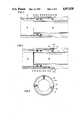
- FIG. 1is an axial cross-sectional illustration of a female connector and a male connector in accord with the present invention
- FIG. 2is an axial cross-sectional illustration of a male and female connector in accord with the present invention just prior to engagement of the upset threads;
- FIG. 3is an axial cross-sectional illustration of a male and female connector in accord with the present invention with the upset threads fully engaged and the first of two O-ring seals made up:
- FIG. 4is an axial cross-sectional illustration of a male and female connector in accord with the present invention fully assembled, illustrating both O-ring seals made up, the upset threads disengaged and disposed in their cooperating thread relief grooves and the connectors secured with a radial screw:
- FIG. 5is a radial cross-sectional illustration of a made up connector in accord with the present invention through 5--5 of FIG. 4 illustrating the asymmetrically disposed radial screws used for aligning and securing the male and female connectors.
- FIGS. 1-5 of the drawingsillustrate a presently preferred embodiment of an alignable, threaded, sealed connection particularly useful in the high pressure environment encountered by downhole tools used in logging boreholes in the oil and gas drilling industry.
- the illustrated deviceis readily assembled and disassembled.
- Advantageous use of a threaded connection to overcome the high friction of a high pressure O-ring sealis employed.
- the disadvantages of threaded connectionsi.e. the inability to readily orient the connectors and the tendency of threaded connections to lack off, are eliminated by the inclusion of thread relief grooves interior of the threads.
- the threadsare disengaged into the thread relief grooves by continued turning to facilitate unhindered relative rotation of the connectors to any desired orientation where they are secured by conventional means, e.g., radial screws, pins or the like.
- conventional meanse.g., radial screws, pins or the like.
- use of a plurality of asymmertrically distributed radial screwsprovides a convenient means to both orient and secure the connectors.
- a female connectorcomprises tubular connector 10 having a central bore therein. Beginning from the exterior, the central bore includes securing bore 18 and upset female threads 20. Adjacent and interior of threads 20 is thread relief groove 16 tapering at 14 to sealing bore 12. Disposed asymmetrically about securing bore 18 are a plurality of countersunk holes 22.
- the male connector 30also comprises a tubular member with a cylindrical plug configured for mating engagement with the central bore of female tubular connector 10.
- male connector 30comprises aligning and sealing plug 32 for aiding initial alignment of connectors 10, 30 and for mating within sealing bore 12 of female connector 10.
- Disposed in a plurality of annular grooves 38 about sealing plug 32are a plurality of elastomeric O-ring seals 28.
- upset male threads 40with a second thread relief groove 34 disposed adjacent and interior thereof.
- male connector 30includes securing plug 36 configured to mate within securing bore 18.
- Disposed about plug 36are a plurality of asymmetrically distributed radial bores 24 for cooperation with countersunk holes 22 in female connector 10. Bores 24 are tapped for receiving machine screws 26 for securely engaging male connector 30 within female connector 10 when fully assembled and aligned.
- Threads 20, 40are straight threads cut for cooperating engagement.
- threads 20, 40are square threads for improved thrust transmission useful in overcoming the high O-ring seal friction encountered in assembling connectors 10, 30.
- Thread relief grooves 16, 34also must be straight and of sufficient length and depth to accommodate therein, respectively, threads 40, 20. Accordingly, thread relief groove 16 must be at least as long as threads 40 and with a diameter at least as great as the diameter of the ridges of threads 40. Similarly, thread relief groove 34 must be at least as long as threads 20 and with a diameter not greater than the diameter of the ridges of threads 20.
- the diameters of sealing bore 10 and O-ring seals 28are less than the diameter of the ridges of female threads 20 to permit O-ring seals 28 to pass unhindered through threads 20.
- This presently most preferred configurationaides in aligning the connectors and ensuring make up of female threads 20 with male threads 40 as illustrated in FIG. 2.
- Relative rotation of connectors 10, 30engage square threads 20, 40 to pull connectors 10, 30 together.
- square threadsare desirable for transmitting thrust and minimizing the force required to make up the connection, any appropriate thread design may be employed.
- FIG. 3illustrates the assembly partially made up where threads 20, 40 are fully engaged and a first O-ring seal 28 has been brought into sealing engagement with sealing bore 12.
- connectors 10, 30may be freely rotated relative to one another to any desired orientation. Once brought into the desired orientation, connectors 10, 30 are secured by conventional securing means, e.g., screws 26 as illustrated in FIG. 4. In the presently preferred embodiment a plurality of asymmetrically disposed radial bores 24 in male connector 30 and cooperating countersunk holes 22 in female connector 10 are employed to aid alignment by indicating the desired orientation. Relative rotation of connectors 10,30 to bring bores 24 into alignment with holes 22 automatically aligns connectors 10,30. Finally, a plurality of screws 26 are employed to secure together the properly oriented connectors 10, 30.
- FIGS. 1-5provides a seal interior of the threads as illustrated in FIG. 4.
- plug 32 and O-rings 28In order to provide this interior seal the diameters of sealing bore 12, plug 32 and O-rings 28 must be less than the diameter of the ridges of female threads 20.
- This configurationis particularly advantageous in that plug 32 extending through the bore in female connector 10 and into bore 12 aids alignment of threads 20, 40. Accordingly, misalignment, resulting in improper sealing and/or damaged threads is minimized.
- Another advantageis that O-ring seals 28 are protected from burrs which may be present on countersunk holes 22.
- an even greater advantageis the fact that the seal is interior of the minimum wall thickness of the connectors, i.e., the thread relief grooves, and, thus, protects the minimum wall thickness from the pressure differential between the exterior and interior of the connection.
- a seal exterior of threads 20, 40may be desirable, although protection of the thread relief grooves from the pressure differential would be lost.
- bore 18 and plug 36are merely lengthened as required to accommodate placement of annular grooves 38 with O-ring seals 28 between threads 20, 40 and bores 22, 24, respectively. In such a configuration the diameter of O-ring seals 28 and cooperating sealing surfaces 36, 18 are greater than the diameter of the ridges of threads 40 since in this configuration the O-rings need not pass through threads 20.
- the method of the present inventioncomprises inserting male connector 30 into female connector 10 until threads 20, 40 abut as illustrated in FIG. 2. In this position, O-ring seals 28 have passed through threads 20 but do not contact sealing bore 12. Accordingly, no O-ring seal friction has been encountered. Threads 20, 40 are made up by relative rotation of connectors 10, 30. During relative rotation O-ring seals 28 are brought into contact with sealing bore 12. The O-ring friction is overcome by the mechanical advantage of threads 20, 40. See FIG. 3. Continued rotation makes up seals 28, after which threads 20, 40 disengage into thread relief grooves 34, 16, respectively, as illustrated in FIG. 4. At this point, O-ring seals 28 are properly seated against seal bore 12.
- the combined thread length of threads 20, 40must be greater than the distance required to move seals 28 into sealing engagement from the point at which the threads first meet. Seals 28 should first contact seal bore 12 after threads 28, 40 have engaged. After this engagement, the remaining axial length of thread engagement of threads 20, 40 must be greater than the axial width of seals 28. After threads 20, 40 have completely disengaged within their respective thread relief grooves 34, 16, continued relative rotation of connectors 10, 30 brings them into any desired orientation. Once brought into the desired orientation, connectors 10, 30 are secured together by conventional means as earlier described.
- Disassemblingis easily achieved by removing screws 26 and relatively rotating connectors 10, 30 in the opposite direction while pulling them apart. This movement reengages threads 20, 40 to again employ the mechanical advantage of the square threads to overcome the O-ring friction during disassembly.
Landscapes
- Engineering & Computer Science (AREA)
- Mining & Mineral Resources (AREA)
- Physics & Mathematics (AREA)
- Life Sciences & Earth Sciences (AREA)
- Geology (AREA)
- General Engineering & Computer Science (AREA)
- Mechanical Engineering (AREA)
- Geophysics (AREA)
- Environmental & Geological Engineering (AREA)
- Fluid Mechanics (AREA)
- General Life Sciences & Earth Sciences (AREA)
- Geochemistry & Mineralogy (AREA)
- Gasket Seals (AREA)
Abstract
Description
1. Field of the Invention
The present invention generally relates to an apparatus and method for providing an alignable, threaded sealed connection. The present invention is particularly useful in providing such a connection between two tubular members. More specifically, the present invention relates to an apparatus and method wherein a high pressure O-ring seal between mating male and female connectors is brought into sealing engagement with the aid of thrust transmitting threads which then disengage into interior thread relief grooves to permit relative rotation of the connectors for aligning and securing the connectors in a desired orientation.
2. Description of the Background
Seals which must withstand high pressure are employed in many environments. Many applications of high pressure seals are employed in the oil and gas drilling industry. For example, high pressure seals are used in the assembly of tubular devices intended for passage through boreholes in the logging of oil and gas wells. These devices typically employ a plurality of elastomeric, O-ring seals disposed in annular grooves about a male connector inserted within a cooperating female connector. These seals are used to protect the sensitive instruments, including the sensors and electronics, disposed within the logging tools from the harsh environment of the downhole location, including high pressure, high temperature and abrasive drilling fluids.
Because these large diameter, high pressure seals result in higher O-ring friction during assembly, a high assembly force is required. In the past, connections with those seals were simply assembled by forcing the connectors together and using brute force to overcome the high O-ring friction associated with the high pressure, large diameter seals. Although the mechanical advantages of threads in overcoming the O-ring friction was known, threads were not often used. Several reason exist for not employing a threaded make up. Where threads were employed to overcome the O-ring friction, it was not possible to align the connection as may be required after makeup. Accordingly, where an alignable connection was required, the advantages of a threaded makeup were unavailable. Further, threaded connections presented the risk that the threads might back off during use, causing separation of the connection and the possibility that a portion of the tool might be lost in the borehole.
Accordingly, there has been a long felt but unfulfilled need by the users of sealed connections, and particularly users in the oil and gas well logging industry where large diameter, high pressure seals are common, for an easily made up connection with the advantages, but not the disadvantages, associated with threaded makeup with the capability of aligning the connection to a desired orientation.
The present invention provides a new and improved apparatus and method for making up a high pressure, sealed connection. The disclosed apparatus and method utilize threaded makeup to overcome the extremely high O-ring friction associated with a large diameter, high pressure seal. However, after makeup, the present apparatus and method permit the threads to be disengaged into interior thread relief grooves to both prevent back off and permit relative rotation of the connectors to achieve any desired orientation of the connectors. After the desired orientation is achieved the connectors are secured by any conventional means, including radial screws.
An apparatus in accord with the present invention includes a male connector and a female connector. The female connector includes a bore therein with upset female threads extending axially along the bore a first distance and a thread relief groove adjacent and interior thereof and extending axially along the bore a second distance. The male connector includes a cylindrical plug for mating with the female bore, the plug including upset male threads for engaging the female threads and an adjacent and interior thread relief groove both extending axially along the plug. The upset male threads extend not more than the second distance while the thread relief groove extends at least the first distance. Further, the thread relief groove on the female connector is of a sufficiently large diameter and the thread relief groove on the male connector of a sufficiently small diameter to accommodate therein the upset male and female threads, respectively, to permit relative rotation of the male and female connectors when the threads are aligned with their cooperating thread relief grooves.
The female bore and male plug further include mating sealing surfaces with an elastomeric seal means disposed therebetween. In the presently preferred embodiment the seal means comprises an O-ring seal disposed in an annular groove about the end of the male plug for cooperation with a seal bore disposed interiorly of the thread relief groove in the female connector. This configuration advantageously aids alignment of the male and female connectors prior to engagement of the upset threads and protects the O-ring seal during assembly.
Finally, the apparatus includes means for aligning the connectors and means for securing the aligned connectors. In the presently preferred embodiment, a plurality of asymmetrically disposed radial screws placed through countersunk holes near the end of the female connector and threaded into a plurality of tapped bores asymmetrically disposed about the interior end of the male connector provide both the means for aligning and means for securing the connectors.
The method of the present invention comprises threading together male and female connectors with engaging upset threads disposed on each in order to bring a seal means disposed on a seal surface of one connector into sealing engagement with a seal surface on the other connector. The method further includes threading the engaged connectors until the upset threads disengage into adjacent thread relief grooves configured to permit the connectors to rotate relative to one another. Finally, the method comprises rotating the connectors relative to one another to bring them into a desired orientation and securing the connectors together in that desired orientation. The method of the present invention may be advantageously employed with any of the connector pairs disclosed herein.
The device and method of the present invention solves the long felt but unfulfilled need for a high pressure connector employing threaded engagement to overcome the high O-ring seal friction associated with large diameter, high pressure seals together with disengagement of the threads into interior thread relief grooves to permit relative rotation of the connectors to achieve a desired orientation for securing the connectors together. Another advantage of this configuration is that it prevents back-off of the threaded connections and separation of the connectors where high make up torque is not desirable. These and other meritorious features and advantages of the present invention will be more readily appreciated from the following detailed description and claims.
Other features and intended advantages of the present invention will be more readily apparent by the references to the following detailed description in connection with the accompanying drawings, wherein:
FIG. 1 is an axial cross-sectional illustration of a female connector and a male connector in accord with the present invention;
FIG. 2 is an axial cross-sectional illustration of a male and female connector in accord with the present invention just prior to engagement of the upset threads;
FIG. 3 is an axial cross-sectional illustration of a male and female connector in accord with the present invention with the upset threads fully engaged and the first of two O-ring seals made up:
FIG. 4 is an axial cross-sectional illustration of a male and female connector in accord with the present invention fully assembled, illustrating both O-ring seals made up, the upset threads disengaged and disposed in their cooperating thread relief grooves and the connectors secured with a radial screw: and
FIG. 5 is a radial cross-sectional illustration of a made up connector in accord with the present invention through 5--5 of FIG. 4 illustrating the asymmetrically disposed radial screws used for aligning and securing the male and female connectors.
While the invention will be described in connection with the presently preferred embodiment, it will be understood that it is not intended to limit the invention to this embodiment. On the contrary, it is intended to cover all alternatives, modifications and equivalents as may be included in the spirit of the invention as defined in the appended claims.
FIGS. 1-5 of the drawings illustrate a presently preferred embodiment of an alignable, threaded, sealed connection particularly useful in the high pressure environment encountered by downhole tools used in logging boreholes in the oil and gas drilling industry. The illustrated device is readily assembled and disassembled. Advantageous use of a threaded connection to overcome the high friction of a high pressure O-ring seal is employed. However, the disadvantages of threaded connections, i.e. the inability to readily orient the connectors and the tendency of threaded connections to lack off, are eliminated by the inclusion of thread relief grooves interior of the threads. Thus, as the seal is made up the threads are disengaged into the thread relief grooves by continued turning to facilitate unhindered relative rotation of the connectors to any desired orientation where they are secured by conventional means, e.g., radial screws, pins or the like. In fact, use of a plurality of asymmertrically distributed radial screws provides a convenient means to both orient and secure the connectors.
The invention will now be described in connection with the presently most preferred embodiment as illustrated in FIGS. 1-5. In the presently most preferred embodiment a female connector comprisestubular connector 10 having a central bore therein. Beginning from the exterior, the central bore includes securingbore 18 and upsetfemale threads 20. Adjacent and interior ofthreads 20 isthread relief groove 16 tapering at 14 to sealingbore 12. Disposed asymmetrically about securingbore 18 are a plurality ofcountersunk holes 22.
Themale connector 30 also comprises a tubular member with a cylindrical plug configured for mating engagement with the central bore of femaletubular connector 10. Beginning on its end,male connector 30 comprises aligning and sealingplug 32 for aiding initial alignment ofconnectors female connector 10. Disposed in a plurality ofannular grooves 38 about sealingplug 32 are a plurality of elastomeric O-ring seals 28. Next are upsetmale threads 40 with a secondthread relief groove 34 disposed adjacent and interior thereof. Finally,male connector 30 includes securingplug 36 configured to mate within securingbore 18. Disposed aboutplug 36 are a plurality of asymmetrically distributed radial bores 24 for cooperation with countersunkholes 22 infemale connector 10.Bores 24 are tapped for receivingmachine screws 26 for securely engagingmale connector 30 withinfemale connector 10 when fully assembled and aligned.
In the presently most preferred embodiment illustrated in FIG. 1, the diameters of sealingbore 10 and O-ring seals 28 are less than the diameter of the ridges offemale threads 20 to permit O-ring seals 28 to pass unhindered throughthreads 20. This presently most preferred configuration aides in aligning the connectors and ensuring make up offemale threads 20 withmale threads 40 as illustrated in FIG. 2. Relative rotation ofconnectors square threads connectors threads ring seal 28 has been brought into sealing engagement with sealingbore 12. Further rotation continues to pull togetherconnectors ring seals 28 have been brought into sealing engagement with sealingbore 12 andthreads thread relief grooves connectors connectors male connector 30 and cooperating countersunkholes 22 infemale connector 10 are employed to aid alignment by indicating the desired orientation. Relative rotation ofconnectors bores 24 into alignment withholes 22 automatically alignsconnectors screws 26 are employed to secure together the properly orientedconnectors
The presently preferred embodiment as illustrated in FIGS. 1-5 provides a seal interior of the threads as illustrated in FIG. 4. In order to provide this interior seal the diameters of sealingbore 12, plug 32 and O-rings 28 must be less than the diameter of the ridges offemale threads 20. This configuration is particularly advantageous in thatplug 32 extending through the bore infemale connector 10 and intobore 12 aids alignment ofthreads ring seals 28 are protected from burrs which may be present on countersunkholes 22. However, an even greater advantage is the fact that the seal is interior of the minimum wall thickness of the connectors, i.e., the thread relief grooves, and, thus, protects the minimum wall thickness from the pressure differential between the exterior and interior of the connection. In an alternative embodiment a seal exterior ofthreads annular grooves 38 with O-ring seals 28 betweenthreads ring seals 28 and cooperating sealing surfaces 36, 18 are greater than the diameter of the ridges ofthreads 40 since in this configuration the O-rings need not pass throughthreads 20.
The method of the present invention comprises insertingmale connector 30 intofemale connector 10 untilthreads ring seals 28 have passed throughthreads 20 but do not contact sealingbore 12. Accordingly, no O-ring seal friction has been encountered.Threads connectors ring seals 28 are brought into contact with sealingbore 12. The O-ring friction is overcome by the mechanical advantage ofthreads threads thread relief grooves ring seals 28 are properly seated against seal bore 12. In order to ensure that O-ring seals 28 are fully seated, the combined thread length ofthreads seals 28 into sealing engagement from the point at which the threads first meet.Seals 28 should first contact seal bore 12 afterthreads threads seals 28. Afterthreads thread relief grooves connectors connectors
Disassembling is easily achieved by removingscrews 26 and relativelyrotating connectors threads
The foregoing description of the invention has been directed in primary part to a particular preferred embodiment and method in accordance with the requirements of the patent statutes and for purposes of explanation and illustration. It will be apparent, however, to those skilled in the art that many modifications and changes in this specifically described apparatus and method may be made without departing from the scope and spirit of the invention. For example, an alternate placement of O-ring seals 28 exterior ofthreads bore 12 and plug 32 have been shown with straight sides, they alternatively may be tapered. Still further, although O-ring seals 28 are preferably disposed ingrooves 38 inmale connector 30, they alternatively may be disposed in grooves infemale connector 10. Therefore, the invention is not restricted to the particular form of construction and method illustrated and described, but covers all modifications which may fall within the scope of the following claims.
It is applicant's intention in the following claims to cover such modifications and variations as fall within the true spirit and scope of the invention.
Claims (11)
1. An alignable, threaded, sealed connection for connecting a pair of tubular members in a high-pressure borehole environment, comprising:
a female connector section disposed adjacent one end of the tubular members and having an increased diameter upset bore disposed therein communicating with the end of the tubular member and with a smaller interior bore of the tubular member across an upset shoulder disposed therein, said female connector section further including first upset threads spaced axially from said upset shoulder and disposed axially along said upset bore a first interval, and a first thread relief groove spaced interiorly thereof between said first upset thread and said upset shoulder;
a male connector section disposed adjacent one end of the other of the tubular members and including a reduced diameter upset cylindrical plug with a first cylindrical portion adjacent said plug end having a first reduced diameter for mating with the interior bore of said one tubular member carrying said female connector section and a second cylindrical portion intermediate said first cylindrical portion and said other tubular member body having a second reduced diameter for mating with the interior of said upset bore disposed in said female connector section, said male connector section further including second upset threads disposed on said second cylindrical portion and axially spaced from said plug end and axially disposed thereon a second interval for engaging said first upset threads of said female connector section, and a second thread relief groove spaced interiorly thereof between said second upset threads and the tubular member body;
said first thread relief groove extending axially for at least said second interval and having a diameter sufficiently large to accommodate said second upset threads;
said second thread relief groove extending axially for at least said first interval and having a diameter sufficiently small to accommodate said first upset threads;
a first sealing surface comprising the bore through said female connector section and the one tubular member;
a second sealing surface comprising the surface of said cylindrical plug end;
elastomeric seal means disposed between said first and second sealing surfaces for effecting a high pressure seal therebetween;
said first and second upset threads mating upon insertion of said plug section of said male connector section into said upset bore portion of said female connector section and rotation of said pair of tubular members with respect to each other whereby upon continued rotation of said tubular members said plug section first cylindrical portion mates with said interior bore of said one tubular member for effecting engagement of said elastomeric seal means therebetween and permitting continued axial rotational movement between said male and female connector sections for permitting said first upset threads to be displaced into said second thread relief groove and said second upset threads to be displaced into said first thread relief groove; and
means for securing the tubular members together and preventing relative rotational movement therebetween.
2. The connection of claim 1 wherein the axial width of said elastomeric seal means is less than the sum of said first and second intervals.
3. The connection of claim 2 wherein said elastomeric seal means comprises at least one elastomeric O-ring disposed in an annular groove in at least one of said sealing surfaces.
4. The connection of claim 3 wherein said annular groove is disposed in said second sealing surface.
5. The connection of claim 4, wherein said first sealing surface comprises the interior bore of said one tubular member and said second sealing surface comprises the outer surface of said plug end first cylindrical portion.
6. The connection of claim 1 wherein said securing means comprises screws disposed in cooperating radial bores in said tubular members.
7. The connection of claim 1 wherein the diameter of said sealing surfaces and said elastomeric means is less than the diameter of the ridges of said first upset threads.
8. The connection of claim 1 wherein said first and second upset threads are straight threads.
9. The connection of claim 1 wherein said first and second upset threads are square threads.
10. The connection of claim 1, further including alignment and support means cooperating with said male and female connector sections to provide axial alignment and support therebetween after said first and second upset threads have rotated into said second and first thread relief grooves.
11. The connection of claim 10, wherein said alignment and support means comprises:
the portion of said female connector section having an increased upset bore adjacent the outer end thereof, and
the portion of said male connector section plug end second cylindrical portion having a second diameter adjacent the tubular member body for engagingly mating with said female connector portion.
Priority Applications (1)
| Application Number | Priority Date | Filing Date | Title |
|---|---|---|---|
| US07/156,206US4907828A (en) | 1988-02-16 | 1988-02-16 | Alignable, threaded, sealed connection |
Applications Claiming Priority (1)
| Application Number | Priority Date | Filing Date | Title |
|---|---|---|---|
| US07/156,206US4907828A (en) | 1988-02-16 | 1988-02-16 | Alignable, threaded, sealed connection |
Publications (1)
| Publication Number | Publication Date |
|---|---|
| US4907828Atrue US4907828A (en) | 1990-03-13 |
Family
ID=22558565
Family Applications (1)
| Application Number | Title | Priority Date | Filing Date |
|---|---|---|---|
| US07/156,206Expired - Fee RelatedUS4907828A (en) | 1988-02-16 | 1988-02-16 | Alignable, threaded, sealed connection |
Country Status (1)
| Country | Link |
|---|---|
| US (1) | US4907828A (en) |
Cited By (85)
| Publication number | Priority date | Publication date | Assignee | Title |
|---|---|---|---|---|
| US5083820A (en)* | 1988-12-28 | 1992-01-28 | Rehau Ag & Co. | Pipe coupling |
| EP0672817A1 (en)* | 1994-03-17 | 1995-09-20 | Halliburton Company | Gas impermeable static seal |
| US5557900A (en)* | 1995-09-15 | 1996-09-24 | The Shane Group, Inc. | Playground structural member using recycled plastic |
| US6069841A (en)* | 1998-04-17 | 2000-05-30 | Western Atlas International, Inc. | Pressurized lead-in for a seismic streamer cable |
| WO2000077437A1 (en)* | 1999-06-16 | 2000-12-21 | Wolff Steven K | Beveled insert for coupling pipes |
| US6247535B1 (en) | 1998-09-22 | 2001-06-19 | Camco International Inc. | Orienting and locking swivel and method |
| US20010047866A1 (en)* | 1998-12-07 | 2001-12-06 | Cook Robert Lance | Wellbore casing |
| US20020050360A1 (en)* | 1998-12-07 | 2002-05-02 | Cook Robert Lance | Forming a wellbore casing while simultaneously drilling a wellbore |
| US20020060078A1 (en)* | 1998-12-07 | 2002-05-23 | Cook Robert Lance | Forming a wellbore casing while simultaneously drilling a wellbore |
| US20020066576A1 (en)* | 1998-11-16 | 2002-06-06 | Cook Robert Lance | Isolation of subterranean zones |
| US20020074134A1 (en)* | 1999-02-26 | 2002-06-20 | Shell Oil Co. | Apparatus for actuating an annular piston |
| US20020121372A1 (en)* | 1998-11-16 | 2002-09-05 | Shell Oil Co. | Isolation of subterranean zones |
| US6464265B1 (en)* | 1999-10-22 | 2002-10-15 | Moen Incorporated | Modular shower arm mounting system |
| US20020148612A1 (en)* | 1998-11-16 | 2002-10-17 | Shell Oil Co. | Isolation of subterranean zones |
| US20030024708A1 (en)* | 1998-12-07 | 2003-02-06 | Shell Oil Co. | Structral support |
| US6520547B2 (en)* | 2001-02-01 | 2003-02-18 | Phoenix Geometrix, Llc | Quick locking pipe joint for plain or profiled pipe |
| US20030047946A1 (en)* | 2001-09-07 | 2003-03-13 | Harout Ohanesian | Joint system for water well conduit assemblies |
| US6550814B2 (en)* | 2001-08-01 | 2003-04-22 | Institut Francais Du Petrole | High-pressure pipe element consisting of hooped tube sections |
| US20030098154A1 (en)* | 1998-12-07 | 2003-05-29 | Shell Oil Co. | Apparatus for radially expanding tubular members |
| US6575240B1 (en) | 1998-12-07 | 2003-06-10 | Shell Oil Company | System and method for driving pipe |
| US6604763B1 (en)* | 1998-12-07 | 2003-08-12 | Shell Oil Company | Expandable connector |
| US20030222455A1 (en)* | 1999-04-26 | 2003-12-04 | Shell Oil Co. | Expandable connector |
| US20040231855A1 (en)* | 2001-07-06 | 2004-11-25 | Cook Robert Lance | Liner hanger |
| US6823937B1 (en) | 1998-12-07 | 2004-11-30 | Shell Oil Company | Wellhead |
| US6976541B2 (en) | 2000-09-18 | 2005-12-20 | Shell Oil Company | Liner hanger with sliding sleeve valve |
| US7048067B1 (en) | 1999-11-01 | 2006-05-23 | Shell Oil Company | Wellbore casing repair |
| US7055608B2 (en) | 1999-03-11 | 2006-06-06 | Shell Oil Company | Forming a wellbore casing while simultaneously drilling a wellbore |
| US7100685B2 (en) | 2000-10-02 | 2006-09-05 | Enventure Global Technology | Mono-diameter wellbore casing |
| US7100684B2 (en) | 2000-07-28 | 2006-09-05 | Enventure Global Technology | Liner hanger with standoffs |
| US7121352B2 (en) | 1998-11-16 | 2006-10-17 | Enventure Global Technology | Isolation of subterranean zones |
| US7168499B2 (en) | 1998-11-16 | 2007-01-30 | Shell Oil Company | Radial expansion of tubular members |
| US7168496B2 (en) | 2001-07-06 | 2007-01-30 | Eventure Global Technology | Liner hanger |
| US7172024B2 (en) | 2000-10-02 | 2007-02-06 | Shell Oil Company | Mono-diameter wellbore casing |
| US7195064B2 (en) | 1998-12-07 | 2007-03-27 | Enventure Global Technology | Mono-diameter wellbore casing |
| US7231985B2 (en) | 1998-11-16 | 2007-06-19 | Shell Oil Company | Radial expansion of tubular members |
| US7234531B2 (en) | 1999-12-03 | 2007-06-26 | Enventure Global Technology, Llc | Mono-diameter wellbore casing |
| US7258168B2 (en) | 2001-07-27 | 2007-08-21 | Enventure Global Technology L.L.C. | Liner hanger with slip joint sealing members and method of use |
| US7290605B2 (en) | 2001-12-27 | 2007-11-06 | Enventure Global Technology | Seal receptacle using expandable liner hanger |
| US7308755B2 (en) | 2003-06-13 | 2007-12-18 | Shell Oil Company | Apparatus for forming a mono-diameter wellbore casing |
| US7325602B2 (en) | 2000-10-02 | 2008-02-05 | Shell Oil Company | Method and apparatus for forming a mono-diameter wellbore casing |
| US7350563B2 (en) | 1999-07-09 | 2008-04-01 | Enventure Global Technology, L.L.C. | System for lining a wellbore casing |
| US7350564B2 (en) | 1998-12-07 | 2008-04-01 | Enventure Global Technology, L.L.C. | Mono-diameter wellbore casing |
| US7360591B2 (en) | 2002-05-29 | 2008-04-22 | Enventure Global Technology, Llc | System for radially expanding a tubular member |
| US7363984B2 (en) | 1998-12-07 | 2008-04-29 | Enventure Global Technology, Llc | System for radially expanding a tubular member |
| US7377326B2 (en) | 2002-08-23 | 2008-05-27 | Enventure Global Technology, L.L.C. | Magnetic impulse applied sleeve method of forming a wellbore casing |
| US7383889B2 (en) | 2001-11-12 | 2008-06-10 | Enventure Global Technology, Llc | Mono diameter wellbore casing |
| US7398832B2 (en) | 2002-06-10 | 2008-07-15 | Enventure Global Technology, Llc | Mono-diameter wellbore casing |
| US7404444B2 (en) | 2002-09-20 | 2008-07-29 | Enventure Global Technology | Protective sleeve for expandable tubulars |
| US7410000B2 (en) | 2001-01-17 | 2008-08-12 | Enventure Global Technology, Llc. | Mono-diameter wellbore casing |
| US7416027B2 (en) | 2001-09-07 | 2008-08-26 | Enventure Global Technology, Llc | Adjustable expansion cone assembly |
| US7424918B2 (en) | 2002-08-23 | 2008-09-16 | Enventure Global Technology, L.L.C. | Interposed joint sealing layer method of forming a wellbore casing |
| US7438133B2 (en) | 2003-02-26 | 2008-10-21 | Enventure Global Technology, Llc | Apparatus and method for radially expanding and plastically deforming a tubular member |
| US20080265569A1 (en)* | 2005-02-17 | 2008-10-30 | Carcagno Gabriel E | Threaded Joint for Pipes Provided with Seal |
| US7503393B2 (en) | 2003-01-27 | 2009-03-17 | Enventure Global Technology, Inc. | Lubrication system for radially expanding tubular members |
| US7513313B2 (en) | 2002-09-20 | 2009-04-07 | Enventure Global Technology, Llc | Bottom plug for forming a mono diameter wellbore casing |
| US7516991B1 (en)* | 2008-05-20 | 2009-04-14 | Donell Optronics Co., Ltd. | Pipework with a fastening device |
| US7516790B2 (en) | 1999-12-03 | 2009-04-14 | Enventure Global Technology, Llc | Mono-diameter wellbore casing |
| USD591407S1 (en) | 2008-07-08 | 2009-04-28 | Ipex Inc. | Pipe having a spigot end and a bell end |
| US7552776B2 (en) | 1998-12-07 | 2009-06-30 | Enventure Global Technology, Llc | Anchor hangers |
| US7571774B2 (en) | 2002-09-20 | 2009-08-11 | Eventure Global Technology | Self-lubricating expansion mandrel for expandable tubular |
| US7603758B2 (en) | 1998-12-07 | 2009-10-20 | Shell Oil Company | Method of coupling a tubular member |
| US7712522B2 (en) | 2003-09-05 | 2010-05-11 | Enventure Global Technology, Llc | Expansion cone and system |
| US7740076B2 (en) | 2002-04-12 | 2010-06-22 | Enventure Global Technology, L.L.C. | Protective sleeve for threaded connections for expandable liner hanger |
| US7739917B2 (en) | 2002-09-20 | 2010-06-22 | Enventure Global Technology, Llc | Pipe formability evaluation for expandable tubulars |
| US7775290B2 (en) | 2003-04-17 | 2010-08-17 | Enventure Global Technology, Llc | Apparatus for radially expanding and plastically deforming a tubular member |
| US7793721B2 (en) | 2003-03-11 | 2010-09-14 | Eventure Global Technology, Llc | Apparatus for radially expanding and plastically deforming a tubular member |
| US7819185B2 (en) | 2004-08-13 | 2010-10-26 | Enventure Global Technology, Llc | Expandable tubular |
| US7886831B2 (en) | 2003-01-22 | 2011-02-15 | Enventure Global Technology, L.L.C. | Apparatus for radially expanding and plastically deforming a tubular member |
| US7918284B2 (en) | 2002-04-15 | 2011-04-05 | Enventure Global Technology, L.L.C. | Protective sleeve for threaded connections for expandable liner hanger |
| CN102072371A (en)* | 2011-02-11 | 2011-05-25 | 苏州工业园区新凯精密五金有限公司 | Spiral tube connecting piece |
| CN1693164B (en)* | 2004-04-30 | 2011-08-24 | 特拉华资本构成公司 | Drop tube assemblies adapted for use with a liquid reservoir |
| US8007014B2 (en) | 2008-08-22 | 2011-08-30 | Younes Youssef | Axially-tensioned pipe joint |
| US20110248495A1 (en)* | 2010-04-07 | 2011-10-13 | Tony Laplante | Connector and method of making a connection |
| US20120292901A1 (en)* | 2011-05-20 | 2012-11-22 | Bong Jin Sik | Plumbing fitting |
| JP2013513039A (en)* | 2009-11-27 | 2013-04-18 | ヴァルレック・マンネスマン・オイル・アンド・ガス・フランス | Assembly for forming a screw connection, method for assembling and dismantling the connection, and use of the connection in a work riser |
| CN103343682A (en)* | 2013-07-31 | 2013-10-09 | 上海神开石油化工装备股份有限公司 | Anti-drop structure and anti-drop method for wireless inclinometer |
| US20160032660A1 (en)* | 2013-03-01 | 2016-02-04 | Evolution Engineering Inc. | Pinned electromagnetic telemetry gap sub assembly |
| US20170314710A1 (en)* | 2016-04-28 | 2017-11-02 | Asm Automation Sensorik Messtechnik Gmbh | Screw connection |
| US9857005B2 (en) | 2014-01-10 | 2018-01-02 | Wright's Well Control Services, Llc | Fluid connector assembly and method of establishing a fluid connection |
| US20180036751A1 (en)* | 2016-08-04 | 2018-02-08 | Brian Cvetezar | Spray gun |
| US10041308B2 (en)* | 2015-12-09 | 2018-08-07 | Nabors Drilling Technologies Usa, Inc. | Oilfield tubular connection system and method |
| US10309163B2 (en)* | 2013-05-17 | 2019-06-04 | Morph Packers Limited | Pipe coupling |
| US10919058B2 (en) | 2016-08-04 | 2021-02-16 | Brian Cvetezar | Spray gun |
| US11713837B2 (en) | 2020-12-18 | 2023-08-01 | Danfoss A/S | Tube assembly, pressure exchanger and reverse osmosis system |
| US20250012391A1 (en)* | 2021-11-01 | 2025-01-09 | Nippon Thermostat Co., Ltd. | Circulating circuit member, and manufacturing method for circulating circuit member |
Citations (6)
| Publication number | Priority date | Publication date | Assignee | Title |
|---|---|---|---|---|
| US675320A (en)* | 1900-06-07 | 1901-05-28 | Edward A Boyne | Coupling for tubes or pipes. |
| US2094416A (en)* | 1936-09-04 | 1937-09-28 | William F Sheffield | Drilling shaft coupling |
| US2914332A (en)* | 1955-03-25 | 1959-11-24 | Warren A Cervini | Drill adaptor |
| US2932305A (en)* | 1957-08-13 | 1960-04-12 | Robert M Kirche | Mixing attachment for faucets |
| US3392746A (en)* | 1965-09-15 | 1968-07-16 | Stephen A Young | Valve and spout connection |
| US3461877A (en)* | 1966-03-02 | 1969-08-19 | Ernst Trier Morch | Tracheostomy tube construction |
- 1988
- 1988-02-16USUS07/156,206patent/US4907828A/ennot_activeExpired - Fee Related
Patent Citations (6)
| Publication number | Priority date | Publication date | Assignee | Title |
|---|---|---|---|---|
| US675320A (en)* | 1900-06-07 | 1901-05-28 | Edward A Boyne | Coupling for tubes or pipes. |
| US2094416A (en)* | 1936-09-04 | 1937-09-28 | William F Sheffield | Drilling shaft coupling |
| US2914332A (en)* | 1955-03-25 | 1959-11-24 | Warren A Cervini | Drill adaptor |
| US2932305A (en)* | 1957-08-13 | 1960-04-12 | Robert M Kirche | Mixing attachment for faucets |
| US3392746A (en)* | 1965-09-15 | 1968-07-16 | Stephen A Young | Valve and spout connection |
| US3461877A (en)* | 1966-03-02 | 1969-08-19 | Ernst Trier Morch | Tracheostomy tube construction |
Cited By (162)
| Publication number | Priority date | Publication date | Assignee | Title |
|---|---|---|---|---|
| US5083820A (en)* | 1988-12-28 | 1992-01-28 | Rehau Ag & Co. | Pipe coupling |
| EP0672817A1 (en)* | 1994-03-17 | 1995-09-20 | Halliburton Company | Gas impermeable static seal |
| US5557900A (en)* | 1995-09-15 | 1996-09-24 | The Shane Group, Inc. | Playground structural member using recycled plastic |
| US6069841A (en)* | 1998-04-17 | 2000-05-30 | Western Atlas International, Inc. | Pressurized lead-in for a seismic streamer cable |
| US6247535B1 (en) | 1998-09-22 | 2001-06-19 | Camco International Inc. | Orienting and locking swivel and method |
| US7231985B2 (en) | 1998-11-16 | 2007-06-19 | Shell Oil Company | Radial expansion of tubular members |
| US20020066576A1 (en)* | 1998-11-16 | 2002-06-06 | Cook Robert Lance | Isolation of subterranean zones |
| US7275601B2 (en) | 1998-11-16 | 2007-10-02 | Shell Oil Company | Radial expansion of tubular members |
| US7270188B2 (en) | 1998-11-16 | 2007-09-18 | Shell Oil Company | Radial expansion of tubular members |
| US7246667B2 (en) | 1998-11-16 | 2007-07-24 | Shell Oil Company | Radial expansion of tubular members |
| US20020148612A1 (en)* | 1998-11-16 | 2002-10-17 | Shell Oil Co. | Isolation of subterranean zones |
| US7357190B2 (en) | 1998-11-16 | 2008-04-15 | Shell Oil Company | Radial expansion of tubular members |
| US7299881B2 (en) | 1998-11-16 | 2007-11-27 | Shell Oil Company | Radial expansion of tubular members |
| US7168499B2 (en) | 1998-11-16 | 2007-01-30 | Shell Oil Company | Radial expansion of tubular members |
| US7121352B2 (en) | 1998-11-16 | 2006-10-17 | Enventure Global Technology | Isolation of subterranean zones |
| US7108072B2 (en) | 1998-11-16 | 2006-09-19 | Shell Oil Company | Lubrication and self-cleaning system for expansion mandrel |
| US6745845B2 (en) | 1998-11-16 | 2004-06-08 | Shell Oil Company | Isolation of subterranean zones |
| US6712154B2 (en) | 1998-11-16 | 2004-03-30 | Enventure Global Technology | Isolation of subterranean zones |
| US6634431B2 (en) | 1998-11-16 | 2003-10-21 | Robert Lance Cook | Isolation of subterranean zones |
| US20030173090A1 (en)* | 1998-11-16 | 2003-09-18 | Shell Oil Co. | Lubrication and self-cleaning system for expansion mandrel |
| US20020121372A1 (en)* | 1998-11-16 | 2002-09-05 | Shell Oil Co. | Isolation of subterranean zones |
| US7195061B2 (en) | 1998-12-07 | 2007-03-27 | Shell Oil Company | Apparatus for expanding a tubular member |
| US7240728B2 (en) | 1998-12-07 | 2007-07-10 | Shell Oil Company | Expandable tubulars with a radial passage and wall portions with different wall thicknesses |
| US7665532B2 (en) | 1998-12-07 | 2010-02-23 | Shell Oil Company | Pipeline |
| US20030024708A1 (en)* | 1998-12-07 | 2003-02-06 | Shell Oil Co. | Structral support |
| US7603758B2 (en) | 1998-12-07 | 2009-10-20 | Shell Oil Company | Method of coupling a tubular member |
| US7552776B2 (en) | 1998-12-07 | 2009-06-30 | Enventure Global Technology, Llc | Anchor hangers |
| US7434618B2 (en) | 1998-12-07 | 2008-10-14 | Shell Oil Company | Apparatus for expanding a tubular member |
| US6561227B2 (en) | 1998-12-07 | 2003-05-13 | Shell Oil Company | Wellbore casing |
| US20030098154A1 (en)* | 1998-12-07 | 2003-05-29 | Shell Oil Co. | Apparatus for radially expanding tubular members |
| US6575240B1 (en) | 1998-12-07 | 2003-06-10 | Shell Oil Company | System and method for driving pipe |
| US6604763B1 (en)* | 1998-12-07 | 2003-08-12 | Shell Oil Company | Expandable connector |
| US7419009B2 (en) | 1998-12-07 | 2008-09-02 | Shell Oil Company | Apparatus for radially expanding and plastically deforming a tubular member |
| US7363984B2 (en) | 1998-12-07 | 2008-04-29 | Enventure Global Technology, Llc | System for radially expanding a tubular member |
| US7357188B1 (en) | 1998-12-07 | 2008-04-15 | Shell Oil Company | Mono-diameter wellbore casing |
| US7350564B2 (en) | 1998-12-07 | 2008-04-01 | Enventure Global Technology, L.L.C. | Mono-diameter wellbore casing |
| US20010047866A1 (en)* | 1998-12-07 | 2001-12-06 | Cook Robert Lance | Wellbore casing |
| US20020050360A1 (en)* | 1998-12-07 | 2002-05-02 | Cook Robert Lance | Forming a wellbore casing while simultaneously drilling a wellbore |
| US20020060069A1 (en)* | 1998-12-07 | 2002-05-23 | Cook Robert Lance | Forming a wellbore casing while simultaneously drilling a wellbore |
| US7240729B2 (en) | 1998-12-07 | 2007-07-10 | Shell Oil Company | Apparatus for expanding a tubular member |
| US6725919B2 (en) | 1998-12-07 | 2004-04-27 | Shell Oil Company | Forming a wellbore casing while simultaneously drilling a wellbore |
| US6739392B2 (en) | 1998-12-07 | 2004-05-25 | Shell Oil Company | Forming a wellbore casing while simultaneously drilling a wellbore |
| US7077213B2 (en) | 1998-12-07 | 2006-07-18 | Shell Oil Company | Expansion cone for radially expanding tubular members |
| US6758278B2 (en) | 1998-12-07 | 2004-07-06 | Shell Oil Company | Forming a wellbore casing while simultaneously drilling a wellbore |
| US20020060068A1 (en)* | 1998-12-07 | 2002-05-23 | Cook Robert Lance | Forming a wellbore casing while simultaneously drilling a wellbore |
| US6823937B1 (en) | 1998-12-07 | 2004-11-30 | Shell Oil Company | Wellhead |
| US7216701B2 (en) | 1998-12-07 | 2007-05-15 | Shell Oil Company | Apparatus for expanding a tubular member |
| US6892819B2 (en) | 1998-12-07 | 2005-05-17 | Shell Oil Company | Forming a wellbore casing while simultaneously drilling a wellbore |
| US7198100B2 (en) | 1998-12-07 | 2007-04-03 | Shell Oil Company | Apparatus for expanding a tubular member |
| US7077211B2 (en) | 1998-12-07 | 2006-07-18 | Shell Oil Company | Method of creating a casing in a borehole |
| US7195064B2 (en) | 1998-12-07 | 2007-03-27 | Enventure Global Technology | Mono-diameter wellbore casing |
| US20020060078A1 (en)* | 1998-12-07 | 2002-05-23 | Cook Robert Lance | Forming a wellbore casing while simultaneously drilling a wellbore |
| US7174964B2 (en) | 1998-12-07 | 2007-02-13 | Shell Oil Company | Wellhead with radially expanded tubulars |
| US7011161B2 (en) | 1998-12-07 | 2006-03-14 | Shell Oil Company | Structural support |
| US7021390B2 (en) | 1998-12-07 | 2006-04-04 | Shell Oil Company | Tubular liner for wellbore casing |
| US7036582B2 (en) | 1998-12-07 | 2006-05-02 | Shell Oil Company | Expansion cone for radially expanding tubular members |
| US7108061B2 (en) | 1998-12-07 | 2006-09-19 | Shell Oil Company | Expander for a tapered liner with a shoe |
| US7159665B2 (en) | 1998-12-07 | 2007-01-09 | Shell Oil Company | Wellbore casing |
| US7044218B2 (en) | 1998-12-07 | 2006-05-16 | Shell Oil Company | Apparatus for radially expanding tubular members |
| US7048062B2 (en) | 1998-12-07 | 2006-05-23 | Shell Oil Company | Method of selecting tubular members |
| US7147053B2 (en) | 1998-12-07 | 2006-12-12 | Shell Oil Company | Wellhead |
| US7121337B2 (en) | 1998-12-07 | 2006-10-17 | Shell Oil Company | Apparatus for expanding a tubular member |
| US7159667B2 (en) | 1999-02-25 | 2007-01-09 | Shell Oil Company | Method of coupling a tubular member to a preexisting structure |
| US20050183863A1 (en)* | 1999-02-25 | 2005-08-25 | Shell Oil Co. | Method of coupling a tubular member to a preexisting structure |
| US7040396B2 (en) | 1999-02-26 | 2006-05-09 | Shell Oil Company | Apparatus for releasably coupling two elements |
| US20020100593A1 (en)* | 1999-02-26 | 2002-08-01 | Shell Oil Co. | Preload for expansion cone |
| US6631759B2 (en) | 1999-02-26 | 2003-10-14 | Shell Oil Company | Apparatus for radially expanding a tubular member |
| US20020084078A1 (en)* | 1999-02-26 | 2002-07-04 | Shell Oil Co. | Method of operating an apparatus for radially expanding a tubular member |
| US7063142B2 (en) | 1999-02-26 | 2006-06-20 | Shell Oil Company | Method of applying an axial force to an expansion cone |
| US20020100594A1 (en)* | 1999-02-26 | 2002-08-01 | Shell Oil Co. | Wellbore casing |
| US20020074130A1 (en)* | 1999-02-26 | 2002-06-20 | Shell Oil Co. | Apparatus for radially expanding a tubular member |
| US6631769B2 (en) | 1999-02-26 | 2003-10-14 | Shell Oil Company | Method of operating an apparatus for radially expanding a tubular member |
| US6684947B2 (en) | 1999-02-26 | 2004-02-03 | Shell Oil Company | Apparatus for radially expanding a tubular member |
| US7044221B2 (en) | 1999-02-26 | 2006-05-16 | Shell Oil Company | Apparatus for coupling a tubular member to a preexisting structure |
| US6705395B2 (en) | 1999-02-26 | 2004-03-16 | Shell Oil Company | Wellbore casing |
| US20020074134A1 (en)* | 1999-02-26 | 2002-06-20 | Shell Oil Co. | Apparatus for actuating an annular piston |
| US20020096338A1 (en)* | 1999-02-26 | 2002-07-25 | Shell Oil Co. | Method of coupling a tubular member to a preexisting structure |
| US20020092657A1 (en)* | 1999-02-26 | 2002-07-18 | Shell Oil Co. | Method of applying an axial force to an expansion cone |
| US6857473B2 (en) | 1999-02-26 | 2005-02-22 | Shell Oil Company | Method of coupling a tubular member to a preexisting structure |
| US7556092B2 (en) | 1999-02-26 | 2009-07-07 | Enventure Global Technology, Llc | Flow control system for an apparatus for radially expanding tubular members |
| US6966370B2 (en) | 1999-02-26 | 2005-11-22 | Shell Oil Company | Apparatus for actuating an annular piston |
| US7055608B2 (en) | 1999-03-11 | 2006-06-06 | Shell Oil Company | Forming a wellbore casing while simultaneously drilling a wellbore |
| US7438132B2 (en) | 1999-03-11 | 2008-10-21 | Shell Oil Company | Concentric pipes expanded at the pipe ends and method of forming |
| US20030222455A1 (en)* | 1999-04-26 | 2003-12-04 | Shell Oil Co. | Expandable connector |
| US6968618B2 (en) | 1999-04-26 | 2005-11-29 | Shell Oil Company | Expandable connector |
| WO2000077437A1 (en)* | 1999-06-16 | 2000-12-21 | Wolff Steven K | Beveled insert for coupling pipes |
| US6371522B1 (en)* | 1999-06-16 | 2002-04-16 | Steven K. Wolff | Beveled insert for coupling pipes |
| US6454310B1 (en)* | 1999-06-16 | 2002-09-24 | Steven K. Wolff | Beveled insert for coupling pipes |
| US7350563B2 (en) | 1999-07-09 | 2008-04-01 | Enventure Global Technology, L.L.C. | System for lining a wellbore casing |
| US6464265B1 (en)* | 1999-10-22 | 2002-10-15 | Moen Incorporated | Modular shower arm mounting system |
| US7048067B1 (en) | 1999-11-01 | 2006-05-23 | Shell Oil Company | Wellbore casing repair |
| US7516790B2 (en) | 1999-12-03 | 2009-04-14 | Enventure Global Technology, Llc | Mono-diameter wellbore casing |
| US7234531B2 (en) | 1999-12-03 | 2007-06-26 | Enventure Global Technology, Llc | Mono-diameter wellbore casing |
| US7100684B2 (en) | 2000-07-28 | 2006-09-05 | Enventure Global Technology | Liner hanger with standoffs |
| US6976541B2 (en) | 2000-09-18 | 2005-12-20 | Shell Oil Company | Liner hanger with sliding sleeve valve |
| US7172021B2 (en) | 2000-09-18 | 2007-02-06 | Shell Oil Company | Liner hanger with sliding sleeve valve |
| US7146702B2 (en) | 2000-10-02 | 2006-12-12 | Shell Oil Company | Method and apparatus for forming a mono-diameter wellbore casing |
| US7204007B2 (en) | 2000-10-02 | 2007-04-17 | Shell Oil Company | Method and apparatus for forming a mono-diameter wellbore casing |
| US7172024B2 (en) | 2000-10-02 | 2007-02-06 | Shell Oil Company | Mono-diameter wellbore casing |
| US7325602B2 (en) | 2000-10-02 | 2008-02-05 | Shell Oil Company | Method and apparatus for forming a mono-diameter wellbore casing |
| US7201223B2 (en) | 2000-10-02 | 2007-04-10 | Shell Oil Company | Method and apparatus for forming a mono-diameter wellbore casing |
| US7172019B2 (en) | 2000-10-02 | 2007-02-06 | Shell Oil Company | Method and apparatus for forming a mono-diameter wellbore casing |
| US7100685B2 (en) | 2000-10-02 | 2006-09-05 | Enventure Global Technology | Mono-diameter wellbore casing |
| US7363690B2 (en) | 2000-10-02 | 2008-04-29 | Shell Oil Company | Method and apparatus for forming a mono-diameter wellbore casing |
| US7363691B2 (en) | 2000-10-02 | 2008-04-29 | Shell Oil Company | Method and apparatus for forming a mono-diameter wellbore casing |
| US7410000B2 (en) | 2001-01-17 | 2008-08-12 | Enventure Global Technology, Llc. | Mono-diameter wellbore casing |
| US6520547B2 (en)* | 2001-02-01 | 2003-02-18 | Phoenix Geometrix, Llc | Quick locking pipe joint for plain or profiled pipe |
| US7290616B2 (en) | 2001-07-06 | 2007-11-06 | Enventure Global Technology, L.L.C. | Liner hanger |
| US7168496B2 (en) | 2001-07-06 | 2007-01-30 | Eventure Global Technology | Liner hanger |
| US20040231855A1 (en)* | 2001-07-06 | 2004-11-25 | Cook Robert Lance | Liner hanger |
| US7258168B2 (en) | 2001-07-27 | 2007-08-21 | Enventure Global Technology L.L.C. | Liner hanger with slip joint sealing members and method of use |
| US6550814B2 (en)* | 2001-08-01 | 2003-04-22 | Institut Francais Du Petrole | High-pressure pipe element consisting of hooped tube sections |
| WO2003023260A3 (en)* | 2001-09-07 | 2005-08-04 | Harout Ohanesian | Joint system for water well conduit assemblies |
| US20030047946A1 (en)* | 2001-09-07 | 2003-03-13 | Harout Ohanesian | Joint system for water well conduit assemblies |
| US7416027B2 (en) | 2001-09-07 | 2008-08-26 | Enventure Global Technology, Llc | Adjustable expansion cone assembly |
| US7383889B2 (en) | 2001-11-12 | 2008-06-10 | Enventure Global Technology, Llc | Mono diameter wellbore casing |
| US7559365B2 (en) | 2001-11-12 | 2009-07-14 | Enventure Global Technology, Llc | Collapsible expansion cone |
| US7290605B2 (en) | 2001-12-27 | 2007-11-06 | Enventure Global Technology | Seal receptacle using expandable liner hanger |
| US7740076B2 (en) | 2002-04-12 | 2010-06-22 | Enventure Global Technology, L.L.C. | Protective sleeve for threaded connections for expandable liner hanger |
| US7918284B2 (en) | 2002-04-15 | 2011-04-05 | Enventure Global Technology, L.L.C. | Protective sleeve for threaded connections for expandable liner hanger |
| US7360591B2 (en) | 2002-05-29 | 2008-04-22 | Enventure Global Technology, Llc | System for radially expanding a tubular member |
| US7398832B2 (en) | 2002-06-10 | 2008-07-15 | Enventure Global Technology, Llc | Mono-diameter wellbore casing |
| US7424918B2 (en) | 2002-08-23 | 2008-09-16 | Enventure Global Technology, L.L.C. | Interposed joint sealing layer method of forming a wellbore casing |
| US7377326B2 (en) | 2002-08-23 | 2008-05-27 | Enventure Global Technology, L.L.C. | Magnetic impulse applied sleeve method of forming a wellbore casing |
| US7404444B2 (en) | 2002-09-20 | 2008-07-29 | Enventure Global Technology | Protective sleeve for expandable tubulars |
| US7513313B2 (en) | 2002-09-20 | 2009-04-07 | Enventure Global Technology, Llc | Bottom plug for forming a mono diameter wellbore casing |
| US7739917B2 (en) | 2002-09-20 | 2010-06-22 | Enventure Global Technology, Llc | Pipe formability evaluation for expandable tubulars |
| US7571774B2 (en) | 2002-09-20 | 2009-08-11 | Eventure Global Technology | Self-lubricating expansion mandrel for expandable tubular |
| US7886831B2 (en) | 2003-01-22 | 2011-02-15 | Enventure Global Technology, L.L.C. | Apparatus for radially expanding and plastically deforming a tubular member |
| US7503393B2 (en) | 2003-01-27 | 2009-03-17 | Enventure Global Technology, Inc. | Lubrication system for radially expanding tubular members |
| US7438133B2 (en) | 2003-02-26 | 2008-10-21 | Enventure Global Technology, Llc | Apparatus and method for radially expanding and plastically deforming a tubular member |
| US7793721B2 (en) | 2003-03-11 | 2010-09-14 | Eventure Global Technology, Llc | Apparatus for radially expanding and plastically deforming a tubular member |
| US7775290B2 (en) | 2003-04-17 | 2010-08-17 | Enventure Global Technology, Llc | Apparatus for radially expanding and plastically deforming a tubular member |
| US7308755B2 (en) | 2003-06-13 | 2007-12-18 | Shell Oil Company | Apparatus for forming a mono-diameter wellbore casing |
| US7712522B2 (en) | 2003-09-05 | 2010-05-11 | Enventure Global Technology, Llc | Expansion cone and system |
| CN1693164B (en)* | 2004-04-30 | 2011-08-24 | 特拉华资本构成公司 | Drop tube assemblies adapted for use with a liquid reservoir |
| US7819185B2 (en) | 2004-08-13 | 2010-10-26 | Enventure Global Technology, Llc | Expandable tubular |
| US20080265569A1 (en)* | 2005-02-17 | 2008-10-30 | Carcagno Gabriel E | Threaded Joint for Pipes Provided with Seal |
| US7506900B2 (en)* | 2005-02-17 | 2009-03-24 | Tenaris Connections Ag | Threaded joint for pipes provided with seal |
| US7516991B1 (en)* | 2008-05-20 | 2009-04-14 | Donell Optronics Co., Ltd. | Pipework with a fastening device |
| USD591407S1 (en) | 2008-07-08 | 2009-04-28 | Ipex Inc. | Pipe having a spigot end and a bell end |
| US8007014B2 (en) | 2008-08-22 | 2011-08-30 | Younes Youssef | Axially-tensioned pipe joint |
| US9909371B2 (en) | 2009-11-27 | 2018-03-06 | Vallourec Oil And Gas France | Assembly for producing a threaded connection, method for making up and breaking out said connection and use of said connection in a work over riser |
| JP2013513039A (en)* | 2009-11-27 | 2013-04-18 | ヴァルレック・マンネスマン・オイル・アンド・ガス・フランス | Assembly for forming a screw connection, method for assembling and dismantling the connection, and use of the connection in a work riser |
| US20110248495A1 (en)* | 2010-04-07 | 2011-10-13 | Tony Laplante | Connector and method of making a connection |
| CN102072371A (en)* | 2011-02-11 | 2011-05-25 | 苏州工业园区新凯精密五金有限公司 | Spiral tube connecting piece |
| US20120292901A1 (en)* | 2011-05-20 | 2012-11-22 | Bong Jin Sik | Plumbing fitting |
| US9932776B2 (en)* | 2013-03-01 | 2018-04-03 | Evolution Engineering Inc. | Pinned electromagnetic telemetry gap sub assembly |
| US20160032660A1 (en)* | 2013-03-01 | 2016-02-04 | Evolution Engineering Inc. | Pinned electromagnetic telemetry gap sub assembly |
| US10309163B2 (en)* | 2013-05-17 | 2019-06-04 | Morph Packers Limited | Pipe coupling |
| CN103343682A (en)* | 2013-07-31 | 2013-10-09 | 上海神开石油化工装备股份有限公司 | Anti-drop structure and anti-drop method for wireless inclinometer |
| US10697569B2 (en) | 2014-01-10 | 2020-06-30 | David C Wright | Fluid connector assembly and method of establishing a fluid connection |
| US9857005B2 (en) | 2014-01-10 | 2018-01-02 | Wright's Well Control Services, Llc | Fluid connector assembly and method of establishing a fluid connection |
| US10041308B2 (en)* | 2015-12-09 | 2018-08-07 | Nabors Drilling Technologies Usa, Inc. | Oilfield tubular connection system and method |
| US20170314710A1 (en)* | 2016-04-28 | 2017-11-02 | Asm Automation Sensorik Messtechnik Gmbh | Screw connection |
| US10746327B2 (en)* | 2016-04-28 | 2020-08-18 | Asm Automation Sensorik Messtechnik Gmbh | Screw connection |
| US20180036751A1 (en)* | 2016-08-04 | 2018-02-08 | Brian Cvetezar | Spray gun |
| US10512922B2 (en)* | 2016-08-04 | 2019-12-24 | Brian Cvetezar | Spray gun |
| US10315206B2 (en) | 2016-08-04 | 2019-06-11 | Brian Cvetezar | Spray gun |
| US10919058B2 (en) | 2016-08-04 | 2021-02-16 | Brian Cvetezar | Spray gun |
| US11713837B2 (en) | 2020-12-18 | 2023-08-01 | Danfoss A/S | Tube assembly, pressure exchanger and reverse osmosis system |
| US20250012391A1 (en)* | 2021-11-01 | 2025-01-09 | Nippon Thermostat Co., Ltd. | Circulating circuit member, and manufacturing method for circulating circuit member |
Similar Documents
| Publication | Publication Date | Title |
|---|---|---|
| US4907828A (en) | Alignable, threaded, sealed connection | |
| US5908212A (en) | Ultra high torque double shoulder tool joint | |
| AU2002336186B2 (en) | Locking arrangement for a threaded connector | |
| US4534585A (en) | Pipe joint locking device | |
| US4844516A (en) | Connector for coil tubing or the like | |
| US8474876B2 (en) | Cam style anti-rotation key for tubular connections | |
| US12240047B2 (en) | Quick-release coupling for drilling and related methods | |
| AU2002336186A1 (en) | Locking arrangement for a threaded connector | |
| CA2378704C (en) | Connector and method of use of the connector | |
| US20060016590A1 (en) | Downhole Component with A Pressure Equalization Passageway | |
| US10605012B2 (en) | Drop in anti-rotation key | |
| US20200025318A1 (en) | Threaded connections for tubular members | |
| EP3175162B1 (en) | A connector device | |
| CA3114074C (en) | Lobular connection for tubulars | |
| EP3788227B1 (en) | Downhole tool | |
| US11859651B1 (en) | Method and apparatus for securing threaded connections against unwanted rotation |
Legal Events
| Date | Code | Title | Description |
|---|---|---|---|
| AS | Assignment | Owner name:WESTERN ATLAS INTERNATIONAL, INC., 10001 RICHMOND, Free format text:ASSIGNMENT OF ASSIGNORS INTEREST.;ASSIGNOR:CHANG, MICHAEL C.;REEL/FRAME:004838/0227 Effective date:19880216 Owner name:WESTERN ATLAS INTERNATIONAL, INC., A DE CORP.,TEX Free format text:ASSIGNMENT OF ASSIGNORS INTEREST;ASSIGNOR:CHANG, MICHAEL C.;REEL/FRAME:004838/0227 Effective date:19880216 | |
| FEPP | Fee payment procedure | Free format text:PAYOR NUMBER ASSIGNED (ORIGINAL EVENT CODE: ASPN); ENTITY STATUS OF PATENT OWNER: LARGE ENTITY | |
| FPAY | Fee payment | Year of fee payment:4 | |
| FPAY | Fee payment | Year of fee payment:8 | |
| REMI | Maintenance fee reminder mailed | ||
| LAPS | Lapse for failure to pay maintenance fees | ||
| STCH | Information on status: patent discontinuation | Free format text:PATENT EXPIRED DUE TO NONPAYMENT OF MAINTENANCE FEES UNDER 37 CFR 1.362 | |
| FP | Lapsed due to failure to pay maintenance fee | Effective date:20020313 |