US4907658A - Percussive mole boring device with electronic transmitter - Google Patents
Percussive mole boring device with electronic transmitterDownload PDFInfo
- Publication number
- US4907658A US4907658AUS07/250,954US25095488AUS4907658AUS 4907658 AUS4907658 AUS 4907658AUS 25095488 AUS25095488 AUS 25095488AUS 4907658 AUS4907658 AUS 4907658A
- Authority
- US
- United States
- Prior art keywords
- transmitter
- mole
- housing
- boring
- percussive
- Prior art date
- Legal status (The legal status is an assumption and is not a legal conclusion. Google has not performed a legal analysis and makes no representation as to the accuracy of the status listed.)
- Expired - Lifetime
Links
Images


Classifications
- E—FIXED CONSTRUCTIONS
- E21—EARTH OR ROCK DRILLING; MINING
- E21B—EARTH OR ROCK DRILLING; OBTAINING OIL, GAS, WATER, SOLUBLE OR MELTABLE MATERIALS OR A SLURRY OF MINERALS FROM WELLS
- E21B7/00—Special methods or apparatus for drilling
- E21B7/26—Drilling without earth removal, e.g. with self-propelled burrowing devices
- E21B7/267—Drilling devices with senders, e.g. radio-transmitters for position of drilling tool
- E—FIXED CONSTRUCTIONS
- E21—EARTH OR ROCK DRILLING; MINING
- E21B—EARTH OR ROCK DRILLING; OBTAINING OIL, GAS, WATER, SOLUBLE OR MELTABLE MATERIALS OR A SLURRY OF MINERALS FROM WELLS
- E21B47/00—Survey of boreholes or wells
- E21B47/01—Devices for supporting measuring instruments on drill bits, pipes, rods or wirelines; Protecting measuring instruments in boreholes against heat, shock, pressure or the like
- E21B47/013—Devices specially adapted for supporting measuring instruments on drill bits
- E—FIXED CONSTRUCTIONS
- E21—EARTH OR ROCK DRILLING; MINING
- E21B—EARTH OR ROCK DRILLING; OBTAINING OIL, GAS, WATER, SOLUBLE OR MELTABLE MATERIALS OR A SLURRY OF MINERALS FROM WELLS
- E21B47/00—Survey of boreholes or wells
- E21B47/02—Determining slope or direction
- E21B47/022—Determining slope or direction of the borehole, e.g. using geomagnetism
- E21B47/0228—Determining slope or direction of the borehole, e.g. using geomagnetism using electromagnetic energy or detectors therefor
- E21B47/0232—Determining slope or direction of the borehole, e.g. using geomagnetism using electromagnetic energy or detectors therefor at least one of the energy sources or one of the detectors being located on or above the ground surface
- E—FIXED CONSTRUCTIONS
- E21—EARTH OR ROCK DRILLING; MINING
- E21B—EARTH OR ROCK DRILLING; OBTAINING OIL, GAS, WATER, SOLUBLE OR MELTABLE MATERIALS OR A SLURRY OF MINERALS FROM WELLS
- E21B47/00—Survey of boreholes or wells
- E21B47/12—Means for transmitting measuring-signals or control signals from the well to the surface, or from the surface to the well, e.g. for logging while drilling
- E21B47/13—Means for transmitting measuring-signals or control signals from the well to the surface, or from the surface to the well, e.g. for logging while drilling by electromagnetic energy, e.g. radio frequency
- E—FIXED CONSTRUCTIONS
- E21—EARTH OR ROCK DRILLING; MINING
- E21B—EARTH OR ROCK DRILLING; OBTAINING OIL, GAS, WATER, SOLUBLE OR MELTABLE MATERIALS OR A SLURRY OF MINERALS FROM WELLS
- E21B7/00—Special methods or apparatus for drilling
- E21B7/04—Directional drilling
- E—FIXED CONSTRUCTIONS
- E21—EARTH OR ROCK DRILLING; MINING
- E21B—EARTH OR ROCK DRILLING; OBTAINING OIL, GAS, WATER, SOLUBLE OR MELTABLE MATERIALS OR A SLURRY OF MINERALS FROM WELLS
- E21B7/00—Special methods or apparatus for drilling
- E21B7/04—Directional drilling
- E21B7/06—Deflecting the direction of boreholes
- E21B7/068—Deflecting the direction of boreholes drilled by a down-hole drilling motor
Definitions
- This inventionrelates to a percussive mole for underground boring, such as for boring channels or passageways for underground utilities. More particularly, the invention relates to an electronic transmitter for surface detection of the location of the forward end of the mole.
- Earth boring devicesare known in the art and include both guided devices, for which the direction of forward progress of the mole can be controlled, and unguided devices. These devices are used for boring channels underground to allow for the installation of utility lines without necessitating the disturbance of surface obstacles, such as trees, fences, sidewalks and roads. For example, a hole may be bored beneath a road without closing the road and digging an open trench across it. The expense of rebuilding the road after installation of the utility is also avoided. If the obstacle is a building, an earth boring device allows for the installation of a utility line which would have been previously impossible.
- a variety of boring roolsare well-known for digging underground channels, including flexible rod devices, auger devices, pipe pushers, and air or hydraulic powered impact type piercing tools or percussive moles.
- the present inventionis directed solely to percussive moles. These tools may or may not be guided or steerable once they enter the ground. Unguided, uncontrollable systems have a tendency to bury themselves, rise to the surface in the wrong position, or damage underground utility lines. Accordingly, they are used primarily for short bores of up to approximately 100 feet.
- the forward or boring end of a percussive molegenerally includes an anvil which is hit by an internal striker powered by compressed air.
- the rearward end of the moleis connected to a whip hose, which in turn is connected to a flexible air hose connected to a source of compressed air on the surface.
- a percussive moleis the PIERCE AIRROW® pneumatic underground piercing tool or mole. This percussive mole can also be adapted to both push or pull pipes through the ground.
- a guided piercing toolconsists of a slanted nose on a rotatable housing and an electronic instrumentation system for directional control.
- the slanted nosegenerates a deflective side force as the tool bores through the soil, thus permitting the operator to turn the tool in a desired direction.
- the means to appropriately rotate and control the toolare well-known and described in the literature.
- FIG. 1illustrates the general operation of a guided percussive mole earth boring tool as taught in commonly assigned U.S. Pat. No. 4,694,913 which is incorporated by reference.
- Drill rig 1is disposed within launching pit 2 which is excavated to a depth below the level of desired horizontal bore hole 3 under a surface structure, for example, road 4.
- Drilling rig 1is provided with an external source of compressed air 5 and is supported on tracks 6 within pit 2. The compressed air is linked to the drilling mole 7 which is supported at the forward end of hollow sectional drill rod 8.
- Drilling rig 1supports drill rod 8 and permits the addition of further sections of rod as the drilling progresses through the earth.
- Compressed air from compressed air source 5is supplied through hollow drill rod 8 to pneumatic mole 7 which operates a hammer (not shown) to repeatedly contact an anvil member (not shown) connected to external boring element 9 having on angled cutting surface.
- Connector 10is located between the rearward end of drilling mole 7 and includes a plurality of holes 11 for exhausting air from the drilling mole back into bore 3.
- a transmitteror sonde
- the transmittertransmits a signal to an above-ground receiver so that the location of the mole can be determined.
- the transmittermust function in an extremely hostile environment of underground dirt and percussive boring, it is important to protect the transmitter as much as possible.
- a transmitter attached at the rear of the molesuch as to the whiphose linking the mole to the compressed air source. In this location the transmitter (or sonde) is relatively well protected from the high shock load on the mole body caused by the percussive impact.
- the exact location of the drilling bore elementcannot be known with great accuracy, since the distance between the boring element at the front of the mole and the rear of the mole may be quite large, e.g., 3-6 feet.
- the molewould have to proceed for at least one body length before a detector located on the surface would detect that the mole was off-course. By this time it may have deviated to a large degree from the desired path and it may be too late to back the mole out of the bore to try a new bore, or in the case of a steerable boring device, correct the course of the mole back to its desired direction. Additionally, damage to sewers and utilities may have already occurred.
- U.S. Pat. No. 3,746,106shows a transmitter located in a housing between the boring bit and the bore pipe.
- the housingincludes a "window", i.e., an area of the housing which allows transmission of a signal in the desired frequency range.
- the housingalso includes a battery compartment and space for appropriate control circuitry.
- a rubber spaceris included in the battery compartment to continually urge the battery into contact with the terminal block.
- the transmitteris located near the drill bit, the bit is designed to cut a hole through the earth by rotary action, progressively cutting the end face of the bore. Therefore, this design of the transmitter housing would be completely unacceptable in a percussive mole device since the impact on the mole creates shock forces which would quickly render the transmitter non-functional.
- the present inventionis percussive boring tool or percussive mole which includes a position transmitter located near the boring device to transmit an accurate location of the boring device to a surface detector.
- Percussive meansare provided for impacting the mole to move it through the ground.
- these percussive meansinclude an internal striker which strikes a drilling assembly, such as an anvil in the forward or boring end of the mole.
- a whip hoseis connected to the rearward end of the mole.
- the whip hoseis, in turn, connected to a flexible air hose which is connected to a source of compressed air for powering the striker into the anvil.
- the drilling assemblyalso includes a transmitter housing located behind but adjacent the forward or boring end of the mole.
- a transmitteris fixed in the transmitter housing.
- a battery for powering the transmitteralso may be positioned in the housing.
- the transmitter housingincludes at least one window transparent to the transmitter frequency and extending at least partially circumferentially around an exterior surface of the housing.
- a "window"is that portion of the housing which allows transmission from the transmitter, i.e., it does not block or otherwise interfere with the transmitted signal.
- a transmitter coilmay be located externally in a groove of the housing and covered with protective epoxy.
- the transmitted signalis then detected by a surface detector.
- the transmitter and batteryare isolated by high impact absorbers to protect it from damage due to the percussive drive mechanism.
- FIG. 1shows a prior art drilling mole apparatus including a drilling rig and compressed air source.
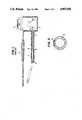
- FIG. 2shows a drilling assembly with a transmitter and housing according to one embodiment of the present invention.
- FIG. 3shows a cross section of the transmitter housing along the lines 3--3 in FIG. 2.
- FIG. 4shows a drilling assembly with a transmitter and housing according to a second embodiment of this invention.
- FIG. 5shows a cross section of the housing along the lines 5--5 in FIG. 4.
- FIG. 2illustrates the invention in the context of a guided percussive boring device.
- drilling assembly 12includes forward end 14 with an angled cutting surface, transmitter housing 16 and hollow connecting element 18 with an open end surface attached within a hollow section at the rear of the transmitter housing.
- Mole 17includes mole body 23 which is fitted into the hollow portion of connecting element 18 and anvil 19.
- Connecting element 18is shown by way of example only, and any suitable means for connecting the mole to the assembly may be used.
- Anvil 19is press fitted into mole body 23 and extends from the forward surface of mole body 23 into the hollow section of housing 16.
- Anvil 19is threadedly engaged with housing 16.
- a hammer or striker(not shown) which is driven by compressed air is located within mole body 23 and repeatedly strikes the anvil causing forward movement of the drilling assembly.
- the mole bodyserves as an anvil or alternatively, the anvil may be a separate part press fit into the tapered forward end of the body and function as a guide or pilot which is repeatedly struck by a hammer.
- the hammeris internal to the mole body and is driven by compressed air.
- the percussive mechanismcan be adapted for whatever the circumstances require and the present invention is not limited to any particular type of percussive mechanism.
- the molemay be of one piece, threadedly connected to the rear of the transmitter housing.
- FIG. 2shows a two piece design for the mole.
- housing 16includes transmitter or sonde 25 located therein.
- the sondemay be of any known type and is commercially available.
- Plastic piece 29is glued to the rear extension surface of sonde 25.
- Screw 27is received within plastic piece 29 and prevents the sonde from rotating with respect to the angled cutting surface. Therefore, the orientation of the sonde with respect to the cutting surface may be known at all times.
- Sonde 25is located beneath window 20 which is transparent to the sonde's transmitting frequency and which extends along the circumferential surface of the housing, for example, for 20°.
- the remaining 340°may be made of material which is not transparent to the frequency.
- the sondemay be controlled by a suitable switch, e.g., a gravity sensitive mercury switch to transmit a continuous signal only when the window is exactly overhead, thus saving energy and providing not only the location of the mole, but also transmitting an accurate description of the orientation of the cutting surface of the boring element with respect to the bore. At all other times the sonde could transmit a pulse signal.
- Sonde 25is securely located between isolators 21 and 22 at both its front and rear ends.
- the isolatorsact as shock absorbers, absorbing the impact of the percussive hammer on the assembly.
- the hammermay strike at a rate of 350-800 blows per minute.
- the isolatorscan be made of any suitable material, for example, a stack of neoprene washers or commercially available ring-type isolators.
- the sondeIn order for the isolation to be effective, the sonde must be free to move slightly in the housing by providing diametric clearance beneath the window. Additionally, the isolation must be maintained by sealing the window against dirt or other contaminants.
- the battery and necessary electronics for the transmitter(not shown) must also be provided in the housing and protected by suitable isolators. These latter elements are commercially available and are known in the art.
- the present inventionnot only allows for effective location of the mole, but also effective direction control when it is desired to change the course.
- the sondemay be provided with a control that emits a continuous signal only when the window is directly overhead, that is, when the sonde is "right-side-up", the exact orientation of the cutting surface can be known with accuracy.
- any orientation of the cutting surfacecan be achieved.
- the forward progress of the molecan be directed by simply stopping progress (terminating percussion) when the window is directly overhead, rotating the mole a desired amount from its overhead orientation, proceeding a desired distance without rotation of the mole until the correct course is achieved, and continuing normal progress with both percussion and rotation.
- Drilling assembly 12' of the second embodimenthas boring element 26 threadedly attached at its forward end.
- the boring elementdoes not include an angled surfaces or other means for providing directional control. Therefore, the drilling assembly is non-guided.
- Sonde 25is shielded between isolators 32 and 34 and is surrounded by three equiangularly located transparent windows 36. These windows, in conjunction with a continually transmitting sonde create a permanent electromagnetic field surrounding the mole near its forward end. Although this mole is not steerable since it does not have an angled cutting surface, the continuous field allows for the precise location of the mole.
- the drilling assemblyincludes a housing for only the battery and control electronics which are isolated as in the previous embodiments.
- the housingdoes not include the window as in the second embodiment. Rather, an externally wound transmitter coil is located in an external groove of the housing and is covered by epoxy to protect it from dirt and rocks. The coil is linked to the isolated battery and electronics within the housing.
Landscapes
- Engineering & Computer Science (AREA)
- Mining & Mineral Resources (AREA)
- Geology (AREA)
- Life Sciences & Earth Sciences (AREA)
- Physics & Mathematics (AREA)
- Fluid Mechanics (AREA)
- Environmental & Geological Engineering (AREA)
- General Life Sciences & Earth Sciences (AREA)
- Geochemistry & Mineralogy (AREA)
- Geophysics (AREA)
- Remote Sensing (AREA)
- Electromagnetism (AREA)
- Earth Drilling (AREA)
Abstract
Description
Claims (7)
Priority Applications (4)
| Application Number | Priority Date | Filing Date | Title |
|---|---|---|---|
| US07/250,954US4907658A (en) | 1988-09-29 | 1988-09-29 | Percussive mole boring device with electronic transmitter |
| CA000612100ACA1335097C (en) | 1988-09-29 | 1989-09-20 | Percussive mole boring device with electronic transmitter |
| EP89309673AEP0361805A1 (en) | 1988-09-29 | 1989-09-22 | Percussive mole boring device with electronic transmitter |
| AU41797/89AAU4179789A (en) | 1988-09-29 | 1989-09-28 | Percussive mole boring device with electronic transmitter |
Applications Claiming Priority (1)
| Application Number | Priority Date | Filing Date | Title |
|---|---|---|---|
| US07/250,954US4907658A (en) | 1988-09-29 | 1988-09-29 | Percussive mole boring device with electronic transmitter |
Publications (1)
| Publication Number | Publication Date |
|---|---|
| US4907658Atrue US4907658A (en) | 1990-03-13 |
Family
ID=22949861
Family Applications (1)
| Application Number | Title | Priority Date | Filing Date |
|---|---|---|---|
| US07/250,954Expired - LifetimeUS4907658A (en) | 1988-09-29 | 1988-09-29 | Percussive mole boring device with electronic transmitter |
Country Status (4)
| Country | Link |
|---|---|
| US (1) | US4907658A (en) |
| EP (1) | EP0361805A1 (en) |
| AU (1) | AU4179789A (en) |
| CA (1) | CA1335097C (en) |
Cited By (55)
| Publication number | Priority date | Publication date | Assignee | Title |
|---|---|---|---|---|
| US5002138A (en)* | 1989-04-28 | 1991-03-26 | Smet Marc J M | Steerable drilling mole |
| US5010965A (en)* | 1989-04-08 | 1991-04-30 | Tracto-Technik Paul Schmidt Maschinenfabrik Kg | Self-propelled ram boring machine |
| US5133417A (en)* | 1990-06-18 | 1992-07-28 | The Charles Machine Works, Inc. | Angle sensor using thermal conductivity for a steerable boring tool |
| US5163520A (en)* | 1991-01-28 | 1992-11-17 | Lag Steering Systems | Apparatus and method for steering a pipe jacking head |
| US5165490A (en)* | 1990-10-03 | 1992-11-24 | Takachiho Sangyo Kabushiki Kaisha | Boring tool having electromagnetic wave generation capability |
| US5255749A (en)* | 1992-03-16 | 1993-10-26 | Steer-Rite, Ltd. | Steerable burrowing mole |
| WO1994005941A1 (en)* | 1992-09-01 | 1994-03-17 | Foster-Miller, Inc. | Guided mole |
| US5350254A (en)* | 1993-11-22 | 1994-09-27 | Foster-Miller, Inc. | Guided mole |
| US5363926A (en)* | 1993-09-21 | 1994-11-15 | Takachiho Sangyo Kabushiki Kaisha | Device for detecting inclination of boring head of boring tool |
| WO1995003472A1 (en)* | 1993-07-20 | 1995-02-02 | Baroid Technology, Inc. | Method and apparatus for controlling the head of a drilling or core-drilling device |
| US5526886A (en)* | 1993-03-23 | 1996-06-18 | Terra Ag Fuer Tiefbautechnik | Ram boring device |
| US5553676A (en)* | 1993-03-22 | 1996-09-10 | Self; Kelvin P. | Reversible expander |
| US5597046A (en)* | 1995-04-12 | 1997-01-28 | Foster-Miller, Inc. | Guided mole |
| US5692576A (en)* | 1994-10-31 | 1997-12-02 | Tracto -Technik Paul Schmidt Spezialmaschinen Kg | Locating device for percussion boring machines |
| US5695014A (en)* | 1994-09-20 | 1997-12-09 | Terra Ag Fuer Tiefbautechnick | Ram boring apparatus |
| US5720354A (en)* | 1996-01-11 | 1998-02-24 | Vermeer Manufacturing Company | Trenchless underground boring system with boring tool location |
| US5720355A (en)* | 1993-07-20 | 1998-02-24 | Baroid Technology, Inc. | Drill bit instrumentation and method for controlling drilling or core-drilling |
| US6002258A (en)* | 1991-03-01 | 1999-12-14 | Digital Control, Inc. | Method for locating a boring tool |
| US6012536A (en)* | 1996-02-27 | 2000-01-11 | Tracto-Technik Schmidt Spezialmaschinen | Method for steering a ground-drilling machine |
| GB2341624A (en)* | 1998-08-27 | 2000-03-22 | Tracto Technik | Method and apparatus for steering ram drills |
| WO2001006085A1 (en)* | 1999-07-16 | 2001-01-25 | Earth Tool Company, L.L.C. | Improved sonde housing structure |
| EP1083292A1 (en) | 1999-09-10 | 2001-03-14 | Earth Tool Company L.L.C. | Interchangeable bit system for directional boring |
| DE19947645C1 (en)* | 1999-10-04 | 2001-03-15 | Tracto Technik | Steering method for directional ground drilling device uses discontinuous rotation of supply line for drilling head for switching between straight and curved drilling modes |
| WO2001025585A2 (en) | 1999-10-04 | 2001-04-12 | Tracto-Technik Gmbh | Guidable land-based rocket |
| US6260634B1 (en) | 1998-08-24 | 2001-07-17 | Earth Tool Company, L.L.C. | Sonde housing for directional drilling |
| US6308787B1 (en) | 1999-09-24 | 2001-10-30 | Vermeer Manufacturing Company | Real-time control system and method for controlling an underground boring machine |
| US6311790B1 (en) | 2000-05-23 | 2001-11-06 | The Charles Machines Works, Inc. | Removable boring head with tapered shank connector |
| US6315062B1 (en) | 1999-09-24 | 2001-11-13 | Vermeer Manufacturing Company | Horizontal directional drilling machine employing inertial navigation control system and method |
| US6349778B1 (en) | 2000-01-04 | 2002-02-26 | Performance Boring Technologies, Inc. | Integrated transmitter surveying while boring entrenching powering device for the continuation of a guided bore hole |
| US6371223B2 (en) | 1999-03-03 | 2002-04-16 | Earth Tool Company, L.L.C. | Drill head for directional boring |
| WO2002035049A1 (en) | 2000-10-23 | 2002-05-02 | Tracto-Technik Gmbh | Steerable soil displacement hammer |
| US6389360B1 (en) | 1999-01-13 | 2002-05-14 | Vermeer Manufacturing Company | Automated bore planning method and apparatus for horizontal directional drilling |
| US6390207B2 (en) | 1999-03-03 | 2002-05-21 | Earth Tool Company, L.L.C. | Method and apparatus for directional boring under mixed conditions |
| US6408952B1 (en) | 1999-12-17 | 2002-06-25 | Vermeer Manufacturing Company | Remote lock-out system and method for a horizontal direction drilling system |
| US6422782B1 (en) | 1999-12-16 | 2002-07-23 | Earth Tool Company, L.L.C. | Apparatus for mounting an electronic device for use in directional drilling |
| US6450269B1 (en) | 2000-09-07 | 2002-09-17 | Earth Tool Company, L.L.C. | Method and bit for directional horizontal boring |
| US6467554B1 (en) | 2001-08-20 | 2002-10-22 | The Charles Machine Works, Inc. | Quick reverse mechanism for pneumatic boring tool |
| US6470979B1 (en) | 1999-07-16 | 2002-10-29 | Earth Tool Company, L.L.C. | Sonde housing structure |
| US6491115B2 (en) | 2000-03-15 | 2002-12-10 | Vermeer Manufacturing Company | Directional drilling machine and method of directional drilling |
| US20030076106A1 (en)* | 1991-03-01 | 2003-04-24 | Mercer John E. | Orientation sensor arrangement and method for use in a system for monitoring the orientation of an underground boring tool |
| US20030152428A1 (en)* | 2001-12-20 | 2003-08-14 | Wentworth Steven W. | Method and apparatus for on-grade boring |
| US20040104046A1 (en)* | 2001-03-01 | 2004-06-03 | Vermeer Manufacturing Company | Macro assisted control system and method for a horizontal directional drilling machine |
| US6761231B1 (en) | 2002-05-06 | 2004-07-13 | The Charles Machines Works, Inc. | Rotary driven drilling hammer |
| US6766869B2 (en) | 1999-12-17 | 2004-07-27 | Vermeer Manufacturing Company | Remote lock-out system and method for a horizontal directional drilling machine |
| US6789635B2 (en) | 2001-06-18 | 2004-09-14 | Earth Tool Company, L.L.C. | Drill bit for directional drilling in cobble formations |
| US6871712B2 (en) | 2001-07-18 | 2005-03-29 | The Charles Machine Works, Inc. | Remote control for a drilling machine |
| US20060006875A1 (en)* | 2004-07-08 | 2006-01-12 | Olsson Mark S | Sondes for locating underground pipes and conduits |
| US20060180244A1 (en)* | 1997-07-24 | 2006-08-17 | Adan Ayala | Portable work bench |
| US20080210468A1 (en)* | 2007-01-29 | 2008-09-04 | Michael Tjader | Drill head connection and method |
| US20090153141A1 (en)* | 1991-03-01 | 2009-06-18 | Mercer John E | Flux Orientation Locating in a Drilling System |
| US20110031018A1 (en)* | 2009-08-04 | 2011-02-10 | Pioneer One, Inc. | Horizontal drilling system |
| US20110155467A1 (en)* | 2009-12-28 | 2011-06-30 | Halliburton Energy Services, Inc. | Timed impact drill bit steering |
| US20110232970A1 (en)* | 2010-03-25 | 2011-09-29 | Halliburton Energy Services, Inc. | Coiled tubing percussion drilling |
| US9121960B2 (en)* | 2006-09-15 | 2015-09-01 | Halliburton Energy Services, Inc. | Multi-axial antenna and method for use in downhole tools |
| US20160356146A1 (en)* | 2014-06-06 | 2016-12-08 | The Charles Machine Works, Inc. | External Hollow Antenna |
Families Citing this family (13)
| Publication number | Priority date | Publication date | Assignee | Title |
|---|---|---|---|---|
| DE3900122C3 (en)* | 1989-01-04 | 1994-02-24 | Schmidt Paul | Ram drilling machine |
| GB8913319D0 (en)* | 1989-06-09 | 1989-07-26 | British Gas Plc | Moling system |
| GB2280463B (en)* | 1990-08-27 | 1995-04-19 | Baroid Technology Inc | Borehole drilling and telemetry |
| FR2674462A1 (en)* | 1991-03-26 | 1992-10-02 | Urbaine Travaux | Method for the manufacture of wear bushes for a drilling device |
| EP0759498B1 (en)* | 1995-08-23 | 2001-11-07 | Tracto-Technik Paul Schmidt Spezialmaschinen | Steerable drlling tool with impact sensitive apparatus |
| DE19534806C2 (en)* | 1995-08-23 | 1999-01-21 | Tracto Technik | Steerable drilling rig |
| DE19650271C2 (en)* | 1996-12-04 | 1999-04-15 | Tracto Technik | Ram drilling machine with at least two sensor or transmitter elements |
| US6234257B1 (en) | 1997-06-02 | 2001-05-22 | Schlumberger Technology Corporation | Deployable sensor apparatus and method |
| US6766854B2 (en) | 1997-06-02 | 2004-07-27 | Schlumberger Technology Corporation | Well-bore sensor apparatus and method |
| DE19823629C2 (en)* | 1998-05-27 | 2001-08-02 | Tracto Technik | Housing for transmitter reception |
| GB9903256D0 (en) | 1999-02-12 | 1999-04-07 | Halco Drilling International L | Directional drilling apparatus |
| US7036609B2 (en)* | 2002-01-14 | 2006-05-02 | Vermeer Manufacturing Company | Sonde housing and method of manufacture |
| DE102009043716B4 (en)* | 2009-10-01 | 2020-04-02 | Tracto-Technik Gmbh & Co. Kg | Drilling element of an earth drilling device |
Citations (15)
| Publication number | Priority date | Publication date | Assignee | Title |
|---|---|---|---|---|
| US3465834A (en)* | 1968-03-18 | 1969-09-09 | Bell Telephone Labor Inc | Guided subterranean penetrator systems |
| US3589454A (en)* | 1968-12-27 | 1971-06-29 | Bell Telephone Labor Inc | Mole guidance system |
| US3712391A (en)* | 1971-06-28 | 1973-01-23 | Bell Telephone Labor Inc | Mole guidance system |
| US3718930A (en)* | 1970-07-06 | 1973-02-27 | Goldak Co Inc | Boring bit locator |
| US3746106A (en)* | 1971-12-27 | 1973-07-17 | Goldak Co Inc | Boring bit locator |
| US4223746A (en)* | 1979-01-29 | 1980-09-23 | Schlumberger Technology Corporation | Shock limiting apparatus |
| US4265305A (en)* | 1979-08-27 | 1981-05-05 | Teleco Oilfield Services Inc. | Mounting and shock absorber assembly for borehole telemetry apparatus |
| US4266606A (en)* | 1979-08-27 | 1981-05-12 | Teleco Oilfield Services Inc. | Hydraulic circuit for borehole telemetry apparatus |
| US4445578A (en)* | 1979-02-28 | 1984-05-01 | Standard Oil Company (Indiana) | System for measuring downhole drilling forces |
| US4592432A (en)* | 1985-06-03 | 1986-06-03 | Williams Russell R | Automatically operated boring head |
| US4621698A (en)* | 1985-04-16 | 1986-11-11 | Gas Research Institute | Percussion boring tool |
| US4632191A (en)* | 1985-04-05 | 1986-12-30 | Gas Research Institute | Steering system for percussion boring tools |
| US4674579A (en)* | 1985-03-07 | 1987-06-23 | Flowmole Corporation | Method and apparatus for installment of underground utilities |
| US4694913A (en)* | 1986-05-16 | 1987-09-22 | Gas Research Institute | Guided earth boring tool |
| US4714118A (en)* | 1986-05-22 | 1987-12-22 | Flowmole Corporation | Technique for steering and monitoring the orientation of a powered underground boring device |
Family Cites Families (8)
| Publication number | Priority date | Publication date | Assignee | Title |
|---|---|---|---|---|
| US3529682A (en)* | 1968-10-03 | 1970-09-22 | Bell Telephone Labor Inc | Location detection and guidance systems for burrowing device |
| FR2058451A5 (en)* | 1969-09-05 | 1971-05-28 | Aquitaine Petrole | |
| DE2847128A1 (en)* | 1978-10-30 | 1980-05-14 | Tracto Technik | Axial position detector for percussion drill - indicates position w.r.t. horizontal using vibration-proofed reference level with electrical sensing and evaluation |
| US4428123A (en)* | 1982-01-28 | 1984-01-31 | Sundstrand Data Control, Inc. | Instrument mounting |
| US4646277A (en)* | 1985-04-12 | 1987-02-24 | Gas Research Institute | Control for guiding a boring tool |
| US4881083A (en)* | 1986-10-02 | 1989-11-14 | Flowmole Corporation | Homing technique for an in-ground boring device |
| DE8804347U1 (en)* | 1987-04-02 | 1988-06-01 | Holloway Equipment Sales Ltd., Gorseinon, West Glamorgan | Locating device for ground displacement hammers |
| US4779852A (en)* | 1987-08-17 | 1988-10-25 | Teleco Oilfield Services Inc. | Vibration isolator and shock absorber device with conical disc springs |
- 1988
- 1988-09-29USUS07/250,954patent/US4907658A/ennot_activeExpired - Lifetime
- 1989
- 1989-09-20CACA000612100Apatent/CA1335097C/ennot_activeExpired - Lifetime
- 1989-09-22EPEP89309673Apatent/EP0361805A1/ennot_activeCeased
- 1989-09-28AUAU41797/89Apatent/AU4179789A/ennot_activeAbandoned
Patent Citations (15)
| Publication number | Priority date | Publication date | Assignee | Title |
|---|---|---|---|---|
| US3465834A (en)* | 1968-03-18 | 1969-09-09 | Bell Telephone Labor Inc | Guided subterranean penetrator systems |
| US3589454A (en)* | 1968-12-27 | 1971-06-29 | Bell Telephone Labor Inc | Mole guidance system |
| US3718930A (en)* | 1970-07-06 | 1973-02-27 | Goldak Co Inc | Boring bit locator |
| US3712391A (en)* | 1971-06-28 | 1973-01-23 | Bell Telephone Labor Inc | Mole guidance system |
| US3746106A (en)* | 1971-12-27 | 1973-07-17 | Goldak Co Inc | Boring bit locator |
| US4223746A (en)* | 1979-01-29 | 1980-09-23 | Schlumberger Technology Corporation | Shock limiting apparatus |
| US4445578A (en)* | 1979-02-28 | 1984-05-01 | Standard Oil Company (Indiana) | System for measuring downhole drilling forces |
| US4265305A (en)* | 1979-08-27 | 1981-05-05 | Teleco Oilfield Services Inc. | Mounting and shock absorber assembly for borehole telemetry apparatus |
| US4266606A (en)* | 1979-08-27 | 1981-05-12 | Teleco Oilfield Services Inc. | Hydraulic circuit for borehole telemetry apparatus |
| US4674579A (en)* | 1985-03-07 | 1987-06-23 | Flowmole Corporation | Method and apparatus for installment of underground utilities |
| US4632191A (en)* | 1985-04-05 | 1986-12-30 | Gas Research Institute | Steering system for percussion boring tools |
| US4621698A (en)* | 1985-04-16 | 1986-11-11 | Gas Research Institute | Percussion boring tool |
| US4592432A (en)* | 1985-06-03 | 1986-06-03 | Williams Russell R | Automatically operated boring head |
| US4694913A (en)* | 1986-05-16 | 1987-09-22 | Gas Research Institute | Guided earth boring tool |
| US4714118A (en)* | 1986-05-22 | 1987-12-22 | Flowmole Corporation | Technique for steering and monitoring the orientation of a powered underground boring device |
Non-Patent Citations (10)
| Title |
|---|
| Publication, "Pierce Arrow", by The Charles Machine Works, Inc., 6/87. |
| Publication, Pierce Arrow , by The Charles Machine Works, Inc., 6/87.* |
| Radiodetection Data Sheet No. 010, 2/87, issued by Radiodetection Corp., "Pipe and Cable Location Theory". |
| Radiodetection Data Sheet No. 010, 2/87, issued by Radiodetection Corp., Pipe and Cable Location Theory .* |
| Radiodetection Data Sheet No. 080, 12/86, issued by Radiodetection Corp., "Sondes for Tracing and Locating Sewers, Drains and Ducts w/the RD300 Drain Locator, the RD400 or RD600 Locating Instruments". |
| Radiodetection Data Sheet No. 080, 12/86, issued by Radiodetection Corp., Sondes for Tracing and Locating Sewers, Drains and Ducts w/the RD300 Drain Locator, the RD400 or RD600 Locating Instruments .* |
| Radiodetection Data Sheet No. 130, 2/87, issued by Radiodetection Corp., "Incorporating a Position Transmitter in a No Dig Tool". |
| Radiodetection Data Sheet No. 130, 2/87, issued by Radiodetection Corp., Incorporating a Position Transmitter in a No Dig Tool .* |
| Radiodetection Data Sheet No. 180, 8/86, issued by Radiodetection Corp., "Safe Working of Horizontal Boring Tools and Maximizing Their Use". |
| Radiodetection Data Sheet No. 180, 8/86, issued by Radiodetection Corp., Safe Working of Horizontal Boring Tools and Maximizing Their Use .* |
Cited By (117)
| Publication number | Priority date | Publication date | Assignee | Title |
|---|---|---|---|---|
| US5010965A (en)* | 1989-04-08 | 1991-04-30 | Tracto-Technik Paul Schmidt Maschinenfabrik Kg | Self-propelled ram boring machine |
| EP0392237A3 (en)* | 1989-04-08 | 1991-11-06 | Tracto-Technik Paul Schmidt, Maschinenfabrik Kg | Self-propelled boring ram |
| US5002138A (en)* | 1989-04-28 | 1991-03-26 | Smet Marc J M | Steerable drilling mole |
| US5078218A (en)* | 1989-04-28 | 1992-01-07 | Marc J. M. Smet | Steerable drilling mole |
| US5133417A (en)* | 1990-06-18 | 1992-07-28 | The Charles Machine Works, Inc. | Angle sensor using thermal conductivity for a steerable boring tool |
| US5165490A (en)* | 1990-10-03 | 1992-11-24 | Takachiho Sangyo Kabushiki Kaisha | Boring tool having electromagnetic wave generation capability |
| US5163520A (en)* | 1991-01-28 | 1992-11-17 | Lag Steering Systems | Apparatus and method for steering a pipe jacking head |
| US20070030006A1 (en)* | 1991-03-01 | 2007-02-08 | Mercer John E | Position and orientation locator/monitor |
| US20080129299A1 (en)* | 1991-03-01 | 2008-06-05 | Mercer John E | Position and Orientation Locator/Monitor |
| US6002258A (en)* | 1991-03-01 | 1999-12-14 | Digital Control, Inc. | Method for locating a boring tool |
| US20030076106A1 (en)* | 1991-03-01 | 2003-04-24 | Mercer John E. | Orientation sensor arrangement and method for use in a system for monitoring the orientation of an underground boring tool |
| US7167005B2 (en) | 1991-03-01 | 2007-01-23 | Merlin Technology, Inc. | Position and orientation locator/monitor |
| US20040140810A1 (en)* | 1991-03-01 | 2004-07-22 | Mercer John E. | Position and orientation locator/monitor |
| US7345486B2 (en) | 1991-03-01 | 2008-03-18 | Merlin Technology, Inc. | Position and orientation locator/monitor |
| US20050073313A1 (en)* | 1991-03-01 | 2005-04-07 | Mercer John E. | Position and orientation locator/monitor |
| US6756784B2 (en) | 1991-03-01 | 2004-06-29 | Merlin Technology, Inc. | Orientation sensor arrangement and method for use in a system for monitoring the orientation of an underground boring tool |
| US6924645B2 (en) | 1991-03-01 | 2005-08-02 | Merlin Technology, Inc. | Position and orientation locator/monitor |
| US7521933B2 (en) | 1991-03-01 | 2009-04-21 | Merlin Technology, Inc. | Position and orientation locator/monitor |
| US20090153141A1 (en)* | 1991-03-01 | 2009-06-18 | Mercer John E | Flux Orientation Locating in a Drilling System |
| US5255749A (en)* | 1992-03-16 | 1993-10-26 | Steer-Rite, Ltd. | Steerable burrowing mole |
| WO1994005941A1 (en)* | 1992-09-01 | 1994-03-17 | Foster-Miller, Inc. | Guided mole |
| US5322391A (en)* | 1992-09-01 | 1994-06-21 | Foster-Miller, Inc. | Guided mole |
| US5553676A (en)* | 1993-03-22 | 1996-09-10 | Self; Kelvin P. | Reversible expander |
| US5526886A (en)* | 1993-03-23 | 1996-06-18 | Terra Ag Fuer Tiefbautechnik | Ram boring device |
| WO1995003472A1 (en)* | 1993-07-20 | 1995-02-02 | Baroid Technology, Inc. | Method and apparatus for controlling the head of a drilling or core-drilling device |
| US5501285A (en)* | 1993-07-20 | 1996-03-26 | Lamine; Etienne | Method for controlling the head of a drilling or core-drilling device and apparatus for carrying out this method |
| US5720355A (en)* | 1993-07-20 | 1998-02-24 | Baroid Technology, Inc. | Drill bit instrumentation and method for controlling drilling or core-drilling |
| US5363926A (en)* | 1993-09-21 | 1994-11-15 | Takachiho Sangyo Kabushiki Kaisha | Device for detecting inclination of boring head of boring tool |
| US5350254A (en)* | 1993-11-22 | 1994-09-27 | Foster-Miller, Inc. | Guided mole |
| US5695014A (en)* | 1994-09-20 | 1997-12-09 | Terra Ag Fuer Tiefbautechnick | Ram boring apparatus |
| US5692576A (en)* | 1994-10-31 | 1997-12-02 | Tracto -Technik Paul Schmidt Spezialmaschinen Kg | Locating device for percussion boring machines |
| US5597046A (en)* | 1995-04-12 | 1997-01-28 | Foster-Miller, Inc. | Guided mole |
| US6435286B1 (en) | 1996-01-11 | 2002-08-20 | Vermeer Manufacturing Company, Inc. | Apparatus and method for detecting a location and an orientation of an underground boring tool |
| US5904210A (en)* | 1996-01-11 | 1999-05-18 | Vermeer Manufacturing Company | Apparatus and method for detecting a location and an orientation of an underground boring tool |
| US6886644B2 (en) | 1996-01-11 | 2005-05-03 | Vermeer Manufacturing Company | Apparatus and method for horizontal drilling |
| US5720354A (en)* | 1996-01-11 | 1998-02-24 | Vermeer Manufacturing Company | Trenchless underground boring system with boring tool location |
| US6161630A (en)* | 1996-01-11 | 2000-12-19 | Vermeer Manufacturing Company | Apparatus and method for controlling an underground boring tool |
| US20050199424A1 (en)* | 1996-01-11 | 2005-09-15 | Vermeer Manufacturing Company, Pella, Ia. | Apparatus and method for horizontal drilling |
| US7182151B2 (en) | 1996-01-11 | 2007-02-27 | Vermeer Manufacturing Company | Apparatus and method for horizontal drilling |
| US5819859A (en)* | 1996-01-11 | 1998-10-13 | Vermeer Manufacturing Company | Apparatus and method for detecting an underground structure |
| US6012536A (en)* | 1996-02-27 | 2000-01-11 | Tracto-Technik Schmidt Spezialmaschinen | Method for steering a ground-drilling machine |
| US20060180244A1 (en)* | 1997-07-24 | 2006-08-17 | Adan Ayala | Portable work bench |
| US6390087B1 (en) | 1998-08-24 | 2002-05-21 | Earth Tool Company. L.L.C. | Drill bit for directional drilling |
| US6588515B2 (en) | 1998-08-24 | 2003-07-08 | Earth Tool Company, L.L.C. | Drill bit for directional drilling |
| US6260634B1 (en) | 1998-08-24 | 2001-07-17 | Earth Tool Company, L.L.C. | Sonde housing for directional drilling |
| US6263983B1 (en) | 1998-08-24 | 2001-07-24 | Earth Tool Company, L.L.C. | Apparatus for directional drilling |
| GB2341624A (en)* | 1998-08-27 | 2000-03-22 | Tracto Technik | Method and apparatus for steering ram drills |
| US6389360B1 (en) | 1999-01-13 | 2002-05-14 | Vermeer Manufacturing Company | Automated bore planning method and apparatus for horizontal directional drilling |
| US20050278123A1 (en)* | 1999-01-13 | 2005-12-15 | Vermeer Manufacturing Company | Automated bore planning system for horizontal directional drilling |
| US6749029B2 (en) | 1999-01-13 | 2004-06-15 | Vermeer Manufacturing Company | Automated bore planning method and apparatus for horizontal directional drilling |
| US6577954B2 (en) | 1999-01-13 | 2003-06-10 | Vermeer Manufacturing Company | Automated bore planning method and apparatus for horizontal directional drilling |
| US6929075B2 (en) | 1999-01-13 | 2005-08-16 | Vermeer Manufacturing Company | Automated bore planning system for horizontal directional drilling |
| US20040243309A1 (en)* | 1999-01-13 | 2004-12-02 | Vermeer Manufacturing Company | Automated bore planning system for horizontal directional drilling |
| US6516899B2 (en) | 1999-03-03 | 2003-02-11 | Earth Tool Company, L.L.C. | Method and apparatus for directional boring under mixed conditions |
| US6439319B1 (en) | 1999-03-03 | 2002-08-27 | Earth Tool Company, L.L.C. | Method and apparatus for directional boring under mixed conditions |
| US6390207B2 (en) | 1999-03-03 | 2002-05-21 | Earth Tool Company, L.L.C. | Method and apparatus for directional boring under mixed conditions |
| US6588516B2 (en) | 1999-03-03 | 2003-07-08 | Vermeer Manufacturing Company | Method and apparatus for directional boring under mixed conditions |
| US6371223B2 (en) | 1999-03-03 | 2002-04-16 | Earth Tool Company, L.L.C. | Drill head for directional boring |
| USRE44427E1 (en) | 1999-03-03 | 2013-08-13 | Vermeer Manufacturing Company | Apparatus for directional boring under mixed conditions |
| GB2360306A (en)* | 1999-07-16 | 2001-09-19 | Earth Tool Co Llc | Improved sonde housing structure |
| WO2001006085A1 (en)* | 1999-07-16 | 2001-01-25 | Earth Tool Company, L.L.C. | Improved sonde housing structure |
| US6470979B1 (en) | 1999-07-16 | 2002-10-29 | Earth Tool Company, L.L.C. | Sonde housing structure |
| EP1083292A1 (en) | 1999-09-10 | 2001-03-14 | Earth Tool Company L.L.C. | Interchangeable bit system for directional boring |
| US6315062B1 (en) | 1999-09-24 | 2001-11-13 | Vermeer Manufacturing Company | Horizontal directional drilling machine employing inertial navigation control system and method |
| US6719069B2 (en) | 1999-09-24 | 2004-04-13 | Vermeer Manufacturing Company | Underground boring machine employing navigation sensor and adjustable steering |
| US7607494B2 (en) | 1999-09-24 | 2009-10-27 | Vermeer Manufacturing Company | Earth penetrating apparatus and method employing radar imaging and rate sensing |
| US6308787B1 (en) | 1999-09-24 | 2001-10-30 | Vermeer Manufacturing Company | Real-time control system and method for controlling an underground boring machine |
| US20050173153A1 (en)* | 1999-09-24 | 2005-08-11 | Vermeer Manufacturing Company, Pella, Ia | Earth penetrating apparatus and method employing radar imaging and rate sensing |
| US7143844B2 (en) | 1999-09-24 | 2006-12-05 | Vermeer Manufacturing Company | Earth penetrating apparatus and method employing radar imaging and rate sensing |
| US6755263B2 (en) | 1999-09-24 | 2004-06-29 | Vermeer Manufacturing Company | Underground drilling device and method employing down-hole radar |
| US6470976B2 (en) | 1999-09-24 | 2002-10-29 | Vermeer Manufacturing Company | Excavation system and method employing adjustable down-hole steering and above-ground tracking |
| US6484818B2 (en) | 1999-09-24 | 2002-11-26 | Vermeer Manufacturing Company | Horizontal directional drilling machine and method employing configurable tracking system interface |
| US20040256159A1 (en)* | 1999-09-24 | 2004-12-23 | Vermeer Manufacturing Company | Underground drilling device employing down-hole radar |
| DE19947645C1 (en)* | 1999-10-04 | 2001-03-15 | Tracto Technik | Steering method for directional ground drilling device uses discontinuous rotation of supply line for drilling head for switching between straight and curved drilling modes |
| WO2001025585A2 (en) | 1999-10-04 | 2001-04-12 | Tracto-Technik Gmbh | Guidable land-based rocket |
| US6422782B1 (en) | 1999-12-16 | 2002-07-23 | Earth Tool Company, L.L.C. | Apparatus for mounting an electronic device for use in directional drilling |
| US6581680B1 (en) | 1999-12-16 | 2003-06-24 | Earth Tool Company, L.L.C. | Apparatus for mounting an electronic device for use in directional drilling |
| US6766869B2 (en) | 1999-12-17 | 2004-07-27 | Vermeer Manufacturing Company | Remote lock-out system and method for a horizontal directional drilling machine |
| US6408952B1 (en) | 1999-12-17 | 2002-06-25 | Vermeer Manufacturing Company | Remote lock-out system and method for a horizontal direction drilling system |
| US6749030B2 (en) | 2000-01-04 | 2004-06-15 | Hunting Performance, Inc. | Integrated transmitter surveying while boring entrenching powering device for the continuation of a guided bore hole |
| US6349778B1 (en) | 2000-01-04 | 2002-02-26 | Performance Boring Technologies, Inc. | Integrated transmitter surveying while boring entrenching powering device for the continuation of a guided bore hole |
| US6491115B2 (en) | 2000-03-15 | 2002-12-10 | Vermeer Manufacturing Company | Directional drilling machine and method of directional drilling |
| US6311790B1 (en) | 2000-05-23 | 2001-11-06 | The Charles Machines Works, Inc. | Removable boring head with tapered shank connector |
| US7392858B2 (en) | 2000-07-18 | 2008-07-01 | The Charles Machine Works, Inc. | Remote control for a drilling machine |
| US20050247483A1 (en)* | 2000-07-18 | 2005-11-10 | Koch Geoff D | Remote control for a drilling machine |
| US6450269B1 (en) | 2000-09-07 | 2002-09-17 | Earth Tool Company, L.L.C. | Method and bit for directional horizontal boring |
| US7270197B2 (en) | 2000-10-23 | 2007-09-18 | Tracto-Technik Gmbh | Steerable soil displacement hammer |
| US20040040748A1 (en)* | 2000-10-23 | 2004-03-04 | Franz-Josef Puttmann | Steerable soil displacement hammer |
| DE10052574C2 (en)* | 2000-10-23 | 2003-02-06 | Tracto Technik | Directable rocket and a method for steering an earth rocket |
| WO2002035049A1 (en) | 2000-10-23 | 2002-05-02 | Tracto-Technik Gmbh | Steerable soil displacement hammer |
| DE10052574A1 (en)* | 2000-10-23 | 2002-05-08 | Tracto Technik | Dirigible Earth Missile |
| US6910541B2 (en) | 2001-03-01 | 2005-06-28 | Vermeer Manufacturing Company | Macro assisted control system and method for a horizontal directional drilling machine |
| US20040104046A1 (en)* | 2001-03-01 | 2004-06-03 | Vermeer Manufacturing Company | Macro assisted control system and method for a horizontal directional drilling machine |
| US6789635B2 (en) | 2001-06-18 | 2004-09-14 | Earth Tool Company, L.L.C. | Drill bit for directional drilling in cobble formations |
| US6871712B2 (en) | 2001-07-18 | 2005-03-29 | The Charles Machine Works, Inc. | Remote control for a drilling machine |
| US6644417B1 (en) | 2001-08-20 | 2003-11-11 | The Charles Machine Works, Inc. | Quick reverse mechanism for pneumatic boring tool |
| US6467554B1 (en) | 2001-08-20 | 2002-10-22 | The Charles Machine Works, Inc. | Quick reverse mechanism for pneumatic boring tool |
| US20030152428A1 (en)* | 2001-12-20 | 2003-08-14 | Wentworth Steven W. | Method and apparatus for on-grade boring |
| US7086808B2 (en) | 2001-12-20 | 2006-08-08 | Earth Tool Company, L.L.C. | Method and apparatus for on-grade boring |
| US6761231B1 (en) | 2002-05-06 | 2004-07-13 | The Charles Machines Works, Inc. | Rotary driven drilling hammer |
| US7298126B1 (en) | 2004-07-08 | 2007-11-20 | Seektech, Inc. | Sondes for locating underground pipes and conduits |
| US7221136B2 (en) | 2004-07-08 | 2007-05-22 | Seektech, Inc. | Sondes for locating underground pipes and conduits |
| US20060006875A1 (en)* | 2004-07-08 | 2006-01-12 | Olsson Mark S | Sondes for locating underground pipes and conduits |
| US7863885B1 (en) | 2004-07-08 | 2011-01-04 | Seektech, Inc. | Sondes for locating underground pipes and conduits |
| US9632201B2 (en) | 2006-09-15 | 2017-04-25 | Halliburton Energy Services, Inc. | Multi-axial antenna and method for use in downhole tools |
| US9121960B2 (en)* | 2006-09-15 | 2015-09-01 | Halliburton Energy Services, Inc. | Multi-axial antenna and method for use in downhole tools |
| US8561721B2 (en)* | 2007-01-29 | 2013-10-22 | Tt Technologies, Inc. | Drill head connection |
| US20080210468A1 (en)* | 2007-01-29 | 2008-09-04 | Michael Tjader | Drill head connection and method |
| US8196677B2 (en) | 2009-08-04 | 2012-06-12 | Pioneer One, Inc. | Horizontal drilling system |
| US8746370B2 (en) | 2009-08-04 | 2014-06-10 | Pioneer One, Inc. | Horizontal drilling system |
| US20110031018A1 (en)* | 2009-08-04 | 2011-02-10 | Pioneer One, Inc. | Horizontal drilling system |
| US20110155467A1 (en)* | 2009-12-28 | 2011-06-30 | Halliburton Energy Services, Inc. | Timed impact drill bit steering |
| US9562394B2 (en) | 2009-12-28 | 2017-02-07 | Halliburton Energy Services, Inc. | Timed impact drill bit steering |
| US20110232970A1 (en)* | 2010-03-25 | 2011-09-29 | Halliburton Energy Services, Inc. | Coiled tubing percussion drilling |
| US20160356146A1 (en)* | 2014-06-06 | 2016-12-08 | The Charles Machine Works, Inc. | External Hollow Antenna |
| US9995132B2 (en)* | 2014-06-06 | 2018-06-12 | The Charles Machine Works, Inc. | External hollow antenna |
| US10677043B2 (en) | 2014-06-06 | 2020-06-09 | The Charles Machine Works, Inc. | External hollow antenna |
Also Published As
| Publication number | Publication date |
|---|---|
| AU4179789A (en) | 1990-04-05 |
| EP0361805A1 (en) | 1990-04-04 |
| CA1335097C (en) | 1995-04-04 |
Similar Documents
| Publication | Publication Date | Title |
|---|---|---|
| US4907658A (en) | Percussive mole boring device with electronic transmitter | |
| EP0247767B1 (en) | Method and apparatus for controlling the direction of a down-hole percussion drilling tool | |
| US4632191A (en) | Steering system for percussion boring tools | |
| US5322391A (en) | Guided mole | |
| US5253721A (en) | Directional boring head | |
| US4621698A (en) | Percussion boring tool | |
| US6659202B2 (en) | Steerable fluid hammer | |
| US7528946B2 (en) | System for detecting deflection of a boring tool | |
| EP0428180B1 (en) | Control system for guiding boring tools and a sensing system for locating the same | |
| US5778987A (en) | Guided drilling system with shock absorber | |
| WO2000052294A3 (en) | Drill head for directional boring | |
| US6397956B1 (en) | Directional drilling tool | |
| PL1682745T3 (en) | Method and device for the drilling of holes in ground or rocky material | |
| RU170031U1 (en) | HORIZONTAL DIRECTIONAL DRILLING INSTALLATION | |
| JP2003066155A (en) | Method and apparatus for detecting ground and mountain states | |
| US20030066685A1 (en) | Steering apparatus | |
| JPH02213585A (en) | Ram boring machine | |
| GB2116723A (en) | Electromagnetic detection of underground objects | |
| US4387776A (en) | Well case driving anvil | |
| SU899792A1 (en) | Percussive device for driving holes in soil by compacting same | |
| GB2188270A (en) | Hammer drill for percussion drilling | |
| Kramer et al. | Steerable Horizontal Boring |
Legal Events
| Date | Code | Title | Description |
|---|---|---|---|
| AS | Assignment | Owner name:GAS RESEARCH INSTITUTE, CHICAGO, IL A NOT-FOR-PROF Free format text:ASSIGNMENT OF ASSIGNORS INTEREST.;ASSIGNORS:STANGI, GERALD A.;LEE, DOUGLAS W.;WILSON, DIRK A.;REEL/FRAME:004978/0721 Effective date:19881118 Owner name:GAS RESEARCH INSTITUTE, A NOT-FOR-PROFIT CORP. OF Free format text:ASSIGNMENT OF ASSIGNORS INTEREST;ASSIGNORS:STANGI, GERALD A.;LEE, DOUGLAS W.;WILSON, DIRK A.;REEL/FRAME:004978/0721 Effective date:19881118 | |
| STCF | Information on status: patent grant | Free format text:PATENTED CASE | |
| FPAY | Fee payment | Year of fee payment:4 | |
| FEPP | Fee payment procedure | Free format text:PAYOR NUMBER ASSIGNED (ORIGINAL EVENT CODE: ASPN); ENTITY STATUS OF PATENT OWNER: LARGE ENTITY | |
| FPAY | Fee payment | Year of fee payment:8 | |
| FPAY | Fee payment | Year of fee payment:12 | |
| AS | Assignment | Owner name:GAS TECHNOLOGY INSTITUTE, ILLINOIS Free format text:ASSIGNMENT OF ASSIGNORS INTEREST;ASSIGNOR:GAS RESEARCH INSTITUTE;REEL/FRAME:017448/0282 Effective date:20060105 |