US4907385A - Drainage apparatus for concrete block walls - Google Patents
Drainage apparatus for concrete block wallsDownload PDFInfo
- Publication number
- US4907385A US4907385AUS07/307,619US30761989AUS4907385AUS 4907385 AUS4907385 AUS 4907385AUS 30761989 AUS30761989 AUS 30761989AUS 4907385 AUS4907385 AUS 4907385A
- Authority
- US
- United States
- Prior art keywords
- fabric
- concrete block
- water
- notch
- block
- Prior art date
- Legal status (The legal status is an assumption and is not a legal conclusion. Google has not performed a legal analysis and makes no representation as to the accuracy of the status listed.)
- Expired - Fee Related
Links
- XLYOFNOQVPJJNP-UHFFFAOYSA-NwaterSubstancesOXLYOFNOQVPJJNP-UHFFFAOYSA-N0.000claimsabstractdescription57
- 239000004744fabricSubstances0.000claimsabstractdescription48
- 239000000463materialSubstances0.000abstractdescription5
- 239000007788liquidSubstances0.000abstractdescription2
- 239000004570mortar (masonry)Substances0.000description10
- 238000010276constructionMethods0.000description6
- 239000011236particulate materialSubstances0.000description2
- 239000002689soilSubstances0.000description2
- 239000004575stoneSubstances0.000description2
- 238000009825accumulationMethods0.000description1
- 238000007792additionMethods0.000description1
- 230000015572biosynthetic processEffects0.000description1
- 238000003780insertionMethods0.000description1
- 230000037431insertionEffects0.000description1
- 238000000034methodMethods0.000description1
- 238000012986modificationMethods0.000description1
- 230000004048modificationEffects0.000description1
- 239000004745nonwoven fabricSubstances0.000description1
- 238000006467substitution reactionMethods0.000description1
Images

Classifications
- E—FIXED CONSTRUCTIONS
- E04—BUILDING
- E04B—GENERAL BUILDING CONSTRUCTIONS; WALLS, e.g. PARTITIONS; ROOFS; FLOORS; CEILINGS; INSULATION OR OTHER PROTECTION OF BUILDINGS
- E04B1/00—Constructions in general; Structures which are not restricted either to walls, e.g. partitions, or floors or ceilings or roofs
- E04B1/62—Insulation or other protection; Elements or use of specified material therefor
- E04B1/70—Drying or keeping dry, e.g. by air vents
- E04B1/703—Evacuating water from walls made from hollow bricks
- E—FIXED CONSTRUCTIONS
- E02—HYDRAULIC ENGINEERING; FOUNDATIONS; SOIL SHIFTING
- E02D—FOUNDATIONS; EXCAVATIONS; EMBANKMENTS; UNDERGROUND OR UNDERWATER STRUCTURES
- E02D31/00—Protective arrangements for foundations or foundation structures; Ground foundation measures for protecting the soil or the subsoil water, e.g. preventing or counteracting oil pollution
- E02D31/02—Protective arrangements for foundations or foundation structures; Ground foundation measures for protecting the soil or the subsoil water, e.g. preventing or counteracting oil pollution against ground humidity or ground water
- E—FIXED CONSTRUCTIONS
- E04—BUILDING
- E04B—GENERAL BUILDING CONSTRUCTIONS; WALLS, e.g. PARTITIONS; ROOFS; FLOORS; CEILINGS; INSULATION OR OTHER PROTECTION OF BUILDINGS
- E04B1/00—Constructions in general; Structures which are not restricted either to walls, e.g. partitions, or floors or ceilings or roofs
- E04B1/0023—Building characterised by incorporated canalisations
- E—FIXED CONSTRUCTIONS
- E04—BUILDING
- E04B—GENERAL BUILDING CONSTRUCTIONS; WALLS, e.g. PARTITIONS; ROOFS; FLOORS; CEILINGS; INSULATION OR OTHER PROTECTION OF BUILDINGS
- E04B1/00—Constructions in general; Structures which are not restricted either to walls, e.g. partitions, or floors or ceilings or roofs
- E04B1/62—Insulation or other protection; Elements or use of specified material therefor
- E04B1/70—Drying or keeping dry, e.g. by air vents
- E04B1/7038—Evacuating water from cavity walls, e.g. by using weep holes
Definitions
- the present inventionrelates to apparatus for draining hollow concrete block walls, and more particularly to an improved drainage apparatus which allows drainage regardless of the extent to which the core of the concrete blocks may be filled with excess mortar and dirt.
- Another object of the present inventionis to provide a wall drainage apparatus which is not subject to plugging by excess mortar or backfill dirt.
- a further objectis to provide drainage apparatus which is simple and economical to install during the construction of the concrete block wall.
- the drainage apparatus of the present inventionis utilized in combination with a hollow core concrete block having a notch extending through one longitudinal wall thereof to allow water to escape the hollow core.
- a fabric pocketis held upright within the hollow core by a wire frame.
- the lower end of the wire frameis bent into a J-shape so as to clip onto the concrete block at the notch in the block.
- the fabricis of a type which will absorb water and permit a high water flow rate, so as to drain water from the surrounding material downwardly through the fabric and out the notch.
- a second embodiment of the inventionutilizes a hollow tubular frame within a fabric pocket.
- the tubular framehas a plurality of slots cut therein to allow water to seep into the tube and be drained out through the notch in the concrete block.
- a third embodiment of the inventionincludes a hollow core concrete block having a notch in its lower edge to drain water from the hollow core, and a channel extending vertically upward from the notch in the core of the block.
- a water conducting fabricis bonded to the concrete block wall over the channel to draw water down the fabric within the channel and thereby drain the liquid through the notch in the concrete block.
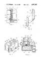
- FIG. 1is a sectional view through a conventional foundation wall and concrete floor slab
- FIG. 2is an exploded perspective view of the drainage apparatus of the present invention
- FIG. 3is a perspective view of the present invention mounted in the lower course of a concrete block wall
- FIG. 4is a sectional view of the lower portion of a basement wall and floor slab with the present invention installed therein;
- FIG. 5is a perspective view of a second embodiment of the present invention installed in the lower course of a concrete block wall.
- FIG. 6is an exploded perspective view of a third embodiment of the invention.
- a conventional concrete block wallis designated generally at 10 and is formed of several vertically-stacked courses of concrete blocks 12 having a hollow interior 14. Each course is separated by a mortar joint 16 such that concrete blocks 12 are stacked with their hollow portions 14 aligned.
- the wall 10is seated on a concrete footing 18, which also supports one edge of the floor slab 20.
- a drainage tile 22is laid in a bed of gravel 24 along the exterior of the wall adjacent to footings 18, to provide some drainage of water from the exterior of the wall.
- Backfill dirt 26then is placed on top of the tile up to ground level 28. Water in the soil is indicated generally by arrows 30 which seeps through mortar joints 16, porous block 12 or cracks or the like so as to flow downwardly through hollow cores 14 within the concrete block wall 10.
- the drainage apparatus of the present inventionis designated generally at 32 and includes a fabric pocket 34 mounted on a wire frame 36.
- Fabric pocket 34preferably consists of a nonwoven fabric with a high water flow rate and high puncture and burst resistance.
- One material which has been found to be suitable for such purposesis produced under the brand name "Mirafi® 140N" by Mirafi, Inc.
- Fabric 34is formed into a pocket shape with an open lower end 38 so as to allow insertion of wire frame 36 therein.
- Wire frame 36includes a pair of parallel and vertically oriented legs 40 connected at their upper end by a cross member 42.
- the lower ends 40a of legs 40are bent into a J-shape orientation having a generally horizontal portion 44 and an upstanding end 46, as shown in the drawings.
- the length of horizontal portion 44is generally equal to the thickness of the wall of the concrete block 48 upon which the drainage apparatus 32 will be mounted. In this way, ends 46 on wire frame 36 will resiliently clip onto the wall of concrete block 48, as shown in FIGS. 3 and 4.
- Wire frame 36is first inserted into fabric pocket 34, such that the lower end 38 of pocket 34 extends completely over legs 40, and thence over horizontal portions 44 at the lower ends 40a of frame 36.
- a pocket 34 of a lengthwhich will extend completely over frame 36 and project upwardly over upstanding ends 46 such that the lower end 38 may be sewed shut as indicated at 40 in FIG. 3, to totally encase the wire frame 36 therein.
- the only critical factor involved with the length of fabric pocket 34is that pocket 34 extend to the lower end 40a of leg members 40.
- Each drainage apparatus 32is installed during construction of a concrete block wall 50, as shown in FIGS. 3 and 4.
- the first, lower course of concrete blocks 48are of a type having a notch 52 cut into the lower edge 54 of one longitudinal wall 48a which extends therethrough into the hollow core 56.
- notches 52were designed to drain water which may collect within cores 56, but were generally ineffective because of excess mortar and backfill dirt, designated generally at 58 in FIG. 4, which would collect and plug notches 52.
- the first course of concrete blocks 48are mounted on footing 18 with notches 52 directed inwardly towards the concrete floor slab 20. As shown in FIG.
- a thin layer of gravel 60is formed adjacent the inner lower edge of concrete blocks 48 and extends across the footing 18 and downwardly to a drainage tile 62. In this fashion, water drained from lower course 48 will flow through gravel 60 to drainage tile 62, and thence to a sump pump or other disposal area.
- a drainage apparatus 32is mounted in each core 56 of each concrete block 48 with the upright legs 46 clipped onto wall 48a of the concrete block.
- fabric pocket 34 and legs 40 of frame 36are of a length which will extend upwardly beyond the first course of concrete blocks 48 partially into the second course of concrete blocks, designated generally at 64, beyond the mortar joint 66 separating the first and second courses.
- the fabric pocket 34 on the drainage device 32acts as a wick to draw water into the material, the water flowing to notch 52 to be drained into gravel 60 and thence to tile 62. Even with the accumulation of excess mortar and backfill dirt 58, the wicking action of fabric pocket 34 will continuously drain water from hollow cores 56.
- FIG. 5A second embodiment of the invention is shown in FIG. 5, and is designated generally at 32'.
- the lower course of concrete blocks 48'each have a notch 52' in the lower edge of one longitudinal face 48a' in a fashion similar to the first embodiment.
- each concrete block 48'is modified by forming a vertical channel 68 on the interior face 70 of longitudinal wall 48a', which extends vertically from notch 52' to the upper edge of block 48'.
- An elongated layer of high water flow rate fabric 72is bonded to wall 70 and extends over channel 68 from the lower edge to slightly above the upper edge of concrete block 48'.
- Fabric 72is of the same type utilized in drainage apparatus 32 of the first embodiment of the invention and serves to draw water through channel 68 and drain the water out through notch 52'.
- fabric 72is preferably bonded to concrete blocks 48' prior to use of the block, such that construction of the concrete wall can proceed without additional time and labor in installing the fabric during construction of the wall.
- a third embodiment of the inventionis designated generally at 32", which differs from the first embodiment 32 in the use of a tubular type frame 74 within the fabric pocket 34".
- Frame 74is formed from an elongated tube 76 which is closed at the upper end 78 and bent at its lower end 80 so as to have a horizontal portion 82 which projects through notch 52" in block 48".
- Elongated tube 76has a series of slots 84 formed therein to allow water to seep into the tube.
- Pocket 34"is fitted over tube 76 so as to act both as a filter and to draw water from the surrounding material into the tube.
Landscapes
- Engineering & Computer Science (AREA)
- Architecture (AREA)
- Civil Engineering (AREA)
- Structural Engineering (AREA)
- Electromagnetism (AREA)
- Life Sciences & Earth Sciences (AREA)
- Physics & Mathematics (AREA)
- Hydrology & Water Resources (AREA)
- General Engineering & Computer Science (AREA)
- Paleontology (AREA)
- Mining & Mineral Resources (AREA)
- General Life Sciences & Earth Sciences (AREA)
- Environmental & Geological Engineering (AREA)
- Underground Structures, Protecting, Testing And Restoring Foundations (AREA)
Abstract
Description
Claims (7)
Priority Applications (2)
| Application Number | Priority Date | Filing Date | Title |
|---|---|---|---|
| US07/307,619US4907385A (en) | 1989-02-07 | 1989-02-07 | Drainage apparatus for concrete block walls |
| CA002009239ACA2009239A1 (en) | 1989-02-07 | 1990-02-02 | Apparatus for draining concrete blocks |
Applications Claiming Priority (1)
| Application Number | Priority Date | Filing Date | Title |
|---|---|---|---|
| US07/307,619US4907385A (en) | 1989-02-07 | 1989-02-07 | Drainage apparatus for concrete block walls |
Publications (1)
| Publication Number | Publication Date |
|---|---|
| US4907385Atrue US4907385A (en) | 1990-03-13 |
Family
ID=23190511
Family Applications (1)
| Application Number | Title | Priority Date | Filing Date |
|---|---|---|---|
| US07/307,619Expired - Fee RelatedUS4907385A (en) | 1989-02-07 | 1989-02-07 | Drainage apparatus for concrete block walls |
Country Status (2)
| Country | Link |
|---|---|
| US (1) | US4907385A (en) |
| CA (1) | CA2009239A1 (en) |
Cited By (38)
| Publication number | Priority date | Publication date | Assignee | Title |
|---|---|---|---|---|
| US5230189A (en)* | 1992-04-02 | 1993-07-27 | Tom Sourlis | Mortar and debris collection device and system |
| US5316410A (en)* | 1992-06-09 | 1994-05-31 | Blume Robert F | Foundation drainage system |
| US5399050A (en)* | 1993-07-06 | 1995-03-21 | Jacobus; James L. | Plastic concrete form for footers |
| US5520481A (en)* | 1994-03-23 | 1996-05-28 | Plastic Tubing Industries, Inc. | Drain field system |
| US5598673A (en)* | 1994-01-18 | 1997-02-04 | Atkins; Mark R. | Masonry cavity wall air space and weeps obstruction prevention system |
| US5694723A (en)* | 1995-05-10 | 1997-12-09 | Parker; Alton F. | Apparatus and method for water drainage and radon removal |
| US5765323A (en)* | 1996-01-04 | 1998-06-16 | Bevilacqua; Joseph | Drainage pipe |
| US5771643A (en)* | 1995-05-10 | 1998-06-30 | Parker; Alton F. | Concrete slab-wall spacer with water and radon removal features |
| US5836115A (en)* | 1996-12-09 | 1998-11-17 | Clay; Randy K. | Foundation waterproofing and drainage system |
| US5845455A (en)* | 1998-01-12 | 1998-12-08 | Masonry Reinforcing Corporation Of America | Mortar collecting device for protecting weep-holes in masonry walls |
| US5870864A (en)* | 1996-10-30 | 1999-02-16 | Snyder; Jeffrey Thomas | Water collection pan for unit masonry wall systems and drainage system incorporating same |
| US5937594A (en)* | 1992-04-02 | 1999-08-17 | Sourlis; Tom | Mortar and debris collection device and system |
| US6112476A (en)* | 1997-11-12 | 2000-09-05 | Masonry Accessories, Llc | Masonry weep hole insert |
| US6202366B1 (en) | 1999-02-11 | 2001-03-20 | Jeffrey Thomas Snyder | Water collection pan for unit masonry wall systems and drainage system incorporating same |
| US20020149482A1 (en)* | 2001-02-12 | 2002-10-17 | Matrics, Inc. | Identification tag utilizing charge pumps for voltage supply generation and data recovery |
| US6550190B2 (en)* | 2001-04-23 | 2003-04-22 | Fas-Flo, Inc. | Drainage system for waterproofing a foundation |
| US20030230035A1 (en)* | 2002-06-17 | 2003-12-18 | Collins P. Michael | Flashing and weep apparatus for masonry wall window and door installations |
| US20040182037A1 (en)* | 2003-03-21 | 2004-09-23 | Tom Sourlis | Drainage system for use in masonry block construction |
| US20040231259A1 (en)* | 2003-05-21 | 2004-11-25 | Tom Sourlis | Drainage system for use in masonry block construction |
| US20040231261A1 (en)* | 2003-03-21 | 2004-11-25 | Mortar Net Uds, Ltd. | Drainage systems for use in masonry block construction |
| US20050055983A1 (en)* | 2003-09-11 | 2005-03-17 | Clear Family Limited Partnership Of C/O Dale Lierman, Esq. | Wall cavity drain panel |
| US6883284B1 (en) | 2003-03-21 | 2005-04-26 | Paul R. Burgunder | Masonry wall device |
| US20050138876A1 (en)* | 2003-05-21 | 2005-06-30 | Tom Sourlis | Drainage system for use in masonry block construction |
| US20050155309A1 (en)* | 2004-01-20 | 2005-07-21 | Anthony Argila | Device for directing mortar droppings/debris, protecting a drainage weep device and draining water from a single wythe wall, the single wythe wall provided with the device, and method of draining water from the single wythe wall |
| US20050262785A1 (en)* | 2004-05-26 | 2005-12-01 | Alexander Ernest E | Masonry wall vent |
| US20080028696A1 (en)* | 2006-08-04 | 2008-02-07 | Octagon Enterprises, Llc | Plug and plate for waterproofing and method for using same |
| US7632408B1 (en) | 2007-06-29 | 2009-12-15 | Plastic Tubing Industries, Inc. | Passive drain field system for wastewater treatment and associated methods |
| US7661903B1 (en) | 2007-04-16 | 2010-02-16 | Plastic Tubing Industries, Inc. | Low-pressure dosing system for sewage disposal and associated methods |
| US7730685B1 (en) | 2003-12-11 | 2010-06-08 | Keene Building Products Co., Inc. | Mortar and debris collection system for masonry cavity walls |
| US8240950B1 (en) | 2007-06-29 | 2012-08-14 | Everson Douglas G | Underground water retention system and associated methods |
| US20120227336A1 (en)* | 2011-03-11 | 2012-09-13 | Trebil Jesse B | Basement waterproofing system compatible with and configured to integrate with radon gas measurement and exhaust components |
| US20150218800A1 (en)* | 2010-10-01 | 2015-08-06 | Christopher John Riggs | Retrofit cavity wall barrier and methods therefor |
| US20150354235A1 (en)* | 2014-06-10 | 2015-12-10 | Harvel K. Crumley | Concrete form tie assembly for monolithic slabs bearing on masonry stem walls |
| US9464429B2 (en)* | 2012-09-05 | 2016-10-11 | Stephen Johnson | Waterproofing system for wet areas |
| US9975272B1 (en) | 2009-04-28 | 2018-05-22 | Natural Stone Wall Solutions | Stone wall construction method |
| US10060126B2 (en) | 2016-02-09 | 2018-08-28 | Ty-Das Building Products, Llc | Starter strip |
| US20190017263A1 (en)* | 2017-07-12 | 2019-01-17 | Nicholas William Myles Burnett | Expansion joint |
| CN112962785A (en)* | 2021-02-03 | 2021-06-15 | 胡鹏 | Precast concrete hollow slab combined building and construction method thereof |
Citations (11)
| Publication number | Priority date | Publication date | Assignee | Title |
|---|---|---|---|---|
| US349735A (en)* | 1886-09-28 | Draining cellars | ||
| US373946A (en)* | 1887-11-29 | The walls of buildings or other structures | ||
| US2292876A (en)* | 1941-02-04 | 1942-08-11 | Glenn V Gladville | Silo |
| US3287866A (en)* | 1963-10-23 | 1966-11-29 | Robert J Rider | Foundation and wall drainage system |
| DE1484461A1 (en)* | 1963-02-20 | 1969-05-29 | Arthur Goehlert | System for draining a building wall |
| US3562982A (en)* | 1969-05-09 | 1971-02-16 | Allen C Parezo | Wall and foundation drain system |
| US3656268A (en)* | 1970-06-23 | 1972-04-18 | Efrahim Murati | Drainage wall system and method of erecting same |
| DE2237707A1 (en)* | 1972-08-01 | 1974-02-07 | Bayer Ag | DRAINAGE ELEMENT FOR EARTH AND GROUND HYDRAULIC ENGINEERING |
| US3852925A (en)* | 1973-06-25 | 1974-12-10 | J Gazzo | Method and means for maintaining a dry basement |
| US4045964A (en)* | 1975-12-15 | 1977-09-06 | Barclay James A | Subterranean panel drain |
| US4523875A (en)* | 1982-12-27 | 1985-06-18 | Difiore Dante | Auxiliary drainage system for eliminating water problems associated with a foundation of a building |
- 1989
- 1989-02-07USUS07/307,619patent/US4907385A/ennot_activeExpired - Fee Related
- 1990
- 1990-02-02CACA002009239Apatent/CA2009239A1/ennot_activeAbandoned
Patent Citations (11)
| Publication number | Priority date | Publication date | Assignee | Title |
|---|---|---|---|---|
| US349735A (en)* | 1886-09-28 | Draining cellars | ||
| US373946A (en)* | 1887-11-29 | The walls of buildings or other structures | ||
| US2292876A (en)* | 1941-02-04 | 1942-08-11 | Glenn V Gladville | Silo |
| DE1484461A1 (en)* | 1963-02-20 | 1969-05-29 | Arthur Goehlert | System for draining a building wall |
| US3287866A (en)* | 1963-10-23 | 1966-11-29 | Robert J Rider | Foundation and wall drainage system |
| US3562982A (en)* | 1969-05-09 | 1971-02-16 | Allen C Parezo | Wall and foundation drain system |
| US3656268A (en)* | 1970-06-23 | 1972-04-18 | Efrahim Murati | Drainage wall system and method of erecting same |
| DE2237707A1 (en)* | 1972-08-01 | 1974-02-07 | Bayer Ag | DRAINAGE ELEMENT FOR EARTH AND GROUND HYDRAULIC ENGINEERING |
| US3852925A (en)* | 1973-06-25 | 1974-12-10 | J Gazzo | Method and means for maintaining a dry basement |
| US4045964A (en)* | 1975-12-15 | 1977-09-06 | Barclay James A | Subterranean panel drain |
| US4523875A (en)* | 1982-12-27 | 1985-06-18 | Difiore Dante | Auxiliary drainage system for eliminating water problems associated with a foundation of a building |
Non-Patent Citations (4)
| Title |
|---|
| Miradrain Advertising Literature.* |
| Miradrain® Advertising Literature. |
| Mirafi 140N Advertising Literature.* |
| Mirafi® 140N Advertising Literature. |
Cited By (50)
| Publication number | Priority date | Publication date | Assignee | Title |
|---|---|---|---|---|
| US5230189A (en)* | 1992-04-02 | 1993-07-27 | Tom Sourlis | Mortar and debris collection device and system |
| US5937594A (en)* | 1992-04-02 | 1999-08-17 | Sourlis; Tom | Mortar and debris collection device and system |
| USRE36676E (en)* | 1992-04-02 | 2000-05-02 | Sourlis; Tom | Mortar and debris collection device and system |
| US5316410A (en)* | 1992-06-09 | 1994-05-31 | Blume Robert F | Foundation drainage system |
| US5399050A (en)* | 1993-07-06 | 1995-03-21 | Jacobus; James L. | Plastic concrete form for footers |
| US5598673A (en)* | 1994-01-18 | 1997-02-04 | Atkins; Mark R. | Masonry cavity wall air space and weeps obstruction prevention system |
| US5520481A (en)* | 1994-03-23 | 1996-05-28 | Plastic Tubing Industries, Inc. | Drain field system |
| US5694723A (en)* | 1995-05-10 | 1997-12-09 | Parker; Alton F. | Apparatus and method for water drainage and radon removal |
| US5771643A (en)* | 1995-05-10 | 1998-06-30 | Parker; Alton F. | Concrete slab-wall spacer with water and radon removal features |
| US5765323A (en)* | 1996-01-04 | 1998-06-16 | Bevilacqua; Joseph | Drainage pipe |
| US5870864A (en)* | 1996-10-30 | 1999-02-16 | Snyder; Jeffrey Thomas | Water collection pan for unit masonry wall systems and drainage system incorporating same |
| US5836115A (en)* | 1996-12-09 | 1998-11-17 | Clay; Randy K. | Foundation waterproofing and drainage system |
| US6112476A (en)* | 1997-11-12 | 2000-09-05 | Masonry Accessories, Llc | Masonry weep hole insert |
| US5845455A (en)* | 1998-01-12 | 1998-12-08 | Masonry Reinforcing Corporation Of America | Mortar collecting device for protecting weep-holes in masonry walls |
| US6202366B1 (en) | 1999-02-11 | 2001-03-20 | Jeffrey Thomas Snyder | Water collection pan for unit masonry wall systems and drainage system incorporating same |
| US20020149482A1 (en)* | 2001-02-12 | 2002-10-17 | Matrics, Inc. | Identification tag utilizing charge pumps for voltage supply generation and data recovery |
| US6550190B2 (en)* | 2001-04-23 | 2003-04-22 | Fas-Flo, Inc. | Drainage system for waterproofing a foundation |
| US20030230035A1 (en)* | 2002-06-17 | 2003-12-18 | Collins P. Michael | Flashing and weep apparatus for masonry wall window and door installations |
| US6964136B2 (en) | 2002-06-17 | 2005-11-15 | Pacc Systems I.P., Llc | Flashing and weep apparatus for masonry wall window and door installations |
| US20040182037A1 (en)* | 2003-03-21 | 2004-09-23 | Tom Sourlis | Drainage system for use in masonry block construction |
| US7726084B2 (en) | 2003-03-21 | 2010-06-01 | Tom Sourlis | Drainage systems for use in masonry block construction |
| US20040231261A1 (en)* | 2003-03-21 | 2004-11-25 | Mortar Net Uds, Ltd. | Drainage systems for use in masonry block construction |
| US7216460B2 (en) | 2003-03-21 | 2007-05-15 | Tom Sourlis | Drainage system for use in masonry block construction |
| US6883284B1 (en) | 2003-03-21 | 2005-04-26 | Paul R. Burgunder | Masonry wall device |
| US6912820B2 (en) | 2003-05-21 | 2005-07-05 | Tom Sourlis | Drainage system for use in masonry block construction |
| US20040231259A1 (en)* | 2003-05-21 | 2004-11-25 | Tom Sourlis | Drainage system for use in masonry block construction |
| US20050138876A1 (en)* | 2003-05-21 | 2005-06-30 | Tom Sourlis | Drainage system for use in masonry block construction |
| US7448175B2 (en) | 2003-05-21 | 2008-11-11 | Tom Sourlis | Drainage system for use in masonry block construction |
| US20050055983A1 (en)* | 2003-09-11 | 2005-03-17 | Clear Family Limited Partnership Of C/O Dale Lierman, Esq. | Wall cavity drain panel |
| US7730685B1 (en) | 2003-12-11 | 2010-06-08 | Keene Building Products Co., Inc. | Mortar and debris collection system for masonry cavity walls |
| US20050155309A1 (en)* | 2004-01-20 | 2005-07-21 | Anthony Argila | Device for directing mortar droppings/debris, protecting a drainage weep device and draining water from a single wythe wall, the single wythe wall provided with the device, and method of draining water from the single wythe wall |
| US7386956B2 (en)* | 2004-01-20 | 2008-06-17 | Anthony Argila | Device for directing mortar droppings/debris, protecting a drainage weep device and draining water from a single wythe wall, the single wythe wall provided with the device, and method of draining water from the single wythe wall |
| US7823349B2 (en) | 2004-05-26 | 2010-11-02 | Alexander Ernest E | Masonry wall vent |
| US20090293394A1 (en)* | 2004-05-26 | 2009-12-03 | Alexander Ernest E | Masonry wall vent |
| US20050262785A1 (en)* | 2004-05-26 | 2005-12-01 | Alexander Ernest E | Masonry wall vent |
| US20080028696A1 (en)* | 2006-08-04 | 2008-02-07 | Octagon Enterprises, Llc | Plug and plate for waterproofing and method for using same |
| US8820013B2 (en)* | 2006-08-04 | 2014-09-02 | Mid-Atlantic Waterproofing Of Md, Inc. | Plug and plate for waterproofing and method for using same |
| US7661903B1 (en) | 2007-04-16 | 2010-02-16 | Plastic Tubing Industries, Inc. | Low-pressure dosing system for sewage disposal and associated methods |
| US7632408B1 (en) | 2007-06-29 | 2009-12-15 | Plastic Tubing Industries, Inc. | Passive drain field system for wastewater treatment and associated methods |
| US8240950B1 (en) | 2007-06-29 | 2012-08-14 | Everson Douglas G | Underground water retention system and associated methods |
| US9975272B1 (en) | 2009-04-28 | 2018-05-22 | Natural Stone Wall Solutions | Stone wall construction method |
| US20150218800A1 (en)* | 2010-10-01 | 2015-08-06 | Christopher John Riggs | Retrofit cavity wall barrier and methods therefor |
| US9309665B2 (en)* | 2010-10-01 | 2016-04-12 | Christopher John Riggs | Retrofit cavity wall barrier and methods therefor |
| US20120227336A1 (en)* | 2011-03-11 | 2012-09-13 | Trebil Jesse B | Basement waterproofing system compatible with and configured to integrate with radon gas measurement and exhaust components |
| US9464429B2 (en)* | 2012-09-05 | 2016-10-11 | Stephen Johnson | Waterproofing system for wet areas |
| US20150354235A1 (en)* | 2014-06-10 | 2015-12-10 | Harvel K. Crumley | Concrete form tie assembly for monolithic slabs bearing on masonry stem walls |
| US9834945B2 (en)* | 2014-06-10 | 2017-12-05 | Harvel K. Crumley | Concrete form tie assembly for monolithic slabs bearing on masonry stem walls |
| US10060126B2 (en) | 2016-02-09 | 2018-08-28 | Ty-Das Building Products, Llc | Starter strip |
| US20190017263A1 (en)* | 2017-07-12 | 2019-01-17 | Nicholas William Myles Burnett | Expansion joint |
| CN112962785A (en)* | 2021-02-03 | 2021-06-15 | 胡鹏 | Precast concrete hollow slab combined building and construction method thereof |
Also Published As
| Publication number | Publication date |
|---|---|
| CA2009239A1 (en) | 1990-08-07 |
Similar Documents
| Publication | Publication Date | Title |
|---|---|---|
| US4907385A (en) | Drainage apparatus for concrete block walls | |
| US10202737B2 (en) | Free-flowing waterproofing system | |
| US4185429A (en) | Apparatus for waterproofing a basement or similar structure | |
| US5845456A (en) | Basement waterproofing | |
| US6550190B2 (en) | Drainage system for waterproofing a foundation | |
| US3852925A (en) | Method and means for maintaining a dry basement | |
| RU2156846C2 (en) | Bank protecting against liquid, process and gear for erection of such protective bank | |
| US5399050A (en) | Plastic concrete form for footers | |
| US4538386A (en) | Drainage system and method | |
| US5784838A (en) | Drain for draining water from a basement floor | |
| US5836115A (en) | Foundation waterproofing and drainage system | |
| US3017722A (en) | Combination hollow footing stringer and foundation drain duct | |
| US20080083175A1 (en) | Method and device for improving drainage away from buildings | |
| US4678369A (en) | Method and arrangement for sealing off dumps to prevent seepage | |
| US5316410A (en) | Foundation drainage system | |
| US5852906A (en) | Internal-wall drain system | |
| US4877350A (en) | Foundation waterproofing method | |
| US6669404B2 (en) | Foundation drain system | |
| KR100616123B1 (en) | Groundwater collection / drainage system of lower ground of underground structure and construction method | |
| US4290252A (en) | Basement waterproofing system | |
| KR101103051B1 (en) | Groundwater drainage | |
| KR100789216B1 (en) | Drainage plate joining structure constructed using nail gun and drainage plate construction method using the same | |
| JPH09119128A (en) | Method for promoting consolidation of soft ground | |
| CN212742561U (en) | Foundation pit supporting structure convenient to modularization installation | |
| KR100658559B1 (en) | Drainage system using drainage plate and perforated pipe |
Legal Events
| Date | Code | Title | Description |
|---|---|---|---|
| FEPP | Fee payment procedure | Free format text:PAYOR NUMBER ASSIGNED (ORIGINAL EVENT CODE: ASPN); ENTITY STATUS OF PATENT OWNER: SMALL ENTITY | |
| FPAY | Fee payment | Year of fee payment:4 | |
| AS | Assignment | Owner name:WITTHUHN, BEVERLY A., NEBRASKA Free format text:ASSIGNMENT OF ASSIGNORS INTEREST;ASSIGNOR:BIODROWSKI, RICHARD E.;REEL/FRAME:007456/0211 Effective date:19940610 Owner name:WITTBUHN, JERRY R., NEBRASKA Free format text:ASSIGNMENT OF ASSIGNORS INTEREST;ASSIGNOR:BIODROWSKI, RICHARD E.;REEL/FRAME:007456/0211 Effective date:19940610 | |
| FEPP | Fee payment procedure | Free format text:PAYER NUMBER DE-ASSIGNED (ORIGINAL EVENT CODE: RMPN); ENTITY STATUS OF PATENT OWNER: SMALL ENTITY | |
| FPAY | Fee payment | Year of fee payment:8 | |
| FEPP | Fee payment procedure | Free format text:PAYOR NUMBER ASSIGNED (ORIGINAL EVENT CODE: ASPN); ENTITY STATUS OF PATENT OWNER: SMALL ENTITY | |
| REMI | Maintenance fee reminder mailed | ||
| LAPS | Lapse for failure to pay maintenance fees | ||
| STCH | Information on status: patent discontinuation | Free format text:PATENT EXPIRED DUE TO NONPAYMENT OF MAINTENANCE FEES UNDER 37 CFR 1.362 | |
| FP | Lapsed due to failure to pay maintenance fee | Effective date:20020313 |