US4907143A - Reflector system for fluorescent troffer - Google Patents
Reflector system for fluorescent trofferDownload PDFInfo
- Publication number
- US4907143A US4907143AUS07/273,093US27309388AUS4907143AUS 4907143 AUS4907143 AUS 4907143AUS 27309388 AUS27309388 AUS 27309388AUS 4907143 AUS4907143 AUS 4907143A
- Authority
- US
- United States
- Prior art keywords
- lamp
- reflector
- louvers
- axis
- pair
- Prior art date
- Legal status (The legal status is an assumption and is not a legal conclusion. Google has not performed a legal analysis and makes no representation as to the accuracy of the status listed.)
- Expired - Fee Related
Links
Images


Classifications
- F—MECHANICAL ENGINEERING; LIGHTING; HEATING; WEAPONS; BLASTING
- F21—LIGHTING
- F21V—FUNCTIONAL FEATURES OR DETAILS OF LIGHTING DEVICES OR SYSTEMS THEREOF; STRUCTURAL COMBINATIONS OF LIGHTING DEVICES WITH OTHER ARTICLES, NOT OTHERWISE PROVIDED FOR
- F21V7/00—Reflectors for light sources
- F21V7/04—Optical design
- F—MECHANICAL ENGINEERING; LIGHTING; HEATING; WEAPONS; BLASTING
- F21—LIGHTING
- F21V—FUNCTIONAL FEATURES OR DETAILS OF LIGHTING DEVICES OR SYSTEMS THEREOF; STRUCTURAL COMBINATIONS OF LIGHTING DEVICES WITH OTHER ARTICLES, NOT OTHERWISE PROVIDED FOR
- F21V11/00—Screens not covered by groups F21V1/00, F21V3/00, F21V7/00 or F21V9/00
- F21V11/06—Screens not covered by groups F21V1/00, F21V3/00, F21V7/00 or F21V9/00 using crossed laminae or strips, e.g. grid-shaped louvers; using lattices or honeycombs
- F—MECHANICAL ENGINEERING; LIGHTING; HEATING; WEAPONS; BLASTING
- F21—LIGHTING
- F21Y—INDEXING SCHEME ASSOCIATED WITH SUBCLASSES F21K, F21L, F21S and F21V, RELATING TO THE FORM OR THE KIND OF THE LIGHT SOURCES OR OF THE COLOUR OF THE LIGHT EMITTED
- F21Y2103/00—Elongate light sources, e.g. fluorescent tubes
- F—MECHANICAL ENGINEERING; LIGHTING; HEATING; WEAPONS; BLASTING
- F21—LIGHTING
- F21Y—INDEXING SCHEME ASSOCIATED WITH SUBCLASSES F21K, F21L, F21S and F21V, RELATING TO THE FORM OR THE KIND OF THE LIGHT SOURCES OR OF THE COLOUR OF THE LIGHT EMITTED
- F21Y2113/00—Combination of light sources
Definitions
- the present inventionrelates to a novel upper reflector system for a fluorescent troffer.
- Troffers of this dimensionhave been produced using two 40 watt u-shaped lamps or four two foot long 20 w lamps.
- 2 ⁇ 2 trofferssupply less than two-thirds of the light of the three lamp 2 ⁇ 4 troffers and must be spaced closer together to produce the same light levels.
- troffers using these lampswould still be unable to serve as a direct replacement for 2 ⁇ 4 troffers because of the poor distribution of light parallel to the lamp axis, i.e. outwardly from the ends of the lamp.
- spacing ratiomay be defined as the horizontal spacing between adjacent troffers divided by the mounting height of the troffers above the working surface. The spacing ratio is used to indicate the maximum spacing which will provide uniform illumination on the surface.
- Existing 2' ⁇ 2' troffersgenerally exhibit spacing ratios of about 1.5 in a plane normal or perpendicular to the lamp axis, but only about 1.2 in a plane parallel to or along the axis of the lamp and intersecting the space to be lighted. For a typical 9' ceiling and a 30" desk height (61/2' mounting height) such 2 ⁇ 2 troffers can therefore be spaced approximately 10' apart perpendicular to the lamp axis, but only 8' apart with the lamps oriented end-to-end.
- Complex electronic devices in the work placeexaccerbate the lighting problem since the floors of such work places are often raised six inches to accommodate cables and wires. Thus, a higher spacing ratio is required in such an area since the floor to ceiling height is decreased.
- glare or brightness from fluorescent troffers at angles of 60° through 90° from nadirmust be controlled in all directions.
- video display terminalsare very susceptible to glare or brightness causing obscuration of characters appearing on the screen.
- the mere adding of additional shielding in a troffer to block this brightnessreduces the overall efficiency of the unit.
- the brightness averaged across the projected area of the troffer(average foot lamberts) could be expected to be twice as great in a 2 ⁇ 2 troffers in a 2 ⁇ 4 troffer at these higher, glare angles.
- U.S. Pat. Nos. 4,065,667, 4,575,788 and 4,651,260describe reflector systems for high intensity discharge lamps generally employed in outdoor environments. Such luminaires in the prior art are generally not adaptable to fluorescent indoor lighting systems.
- U.S. Pat. No. 4,562,517shows an upper reflector system for a fluorescent lighting unit which generally controls distribution of light in the perpendicular or normal plane for use with u-shaped fluorescent tubes and circular fluorescent tubes.
- the fluorescent troffer fixture of the present inventionutilizes an upper reflector system, in combination with conventional louvers running parallel and perpendicular to the axis of the lamp.
- the fixture of the present inventionemploys a double tube fluorescent lamp which is oriented vertically, one tube on top of another tube, in relation to a floor or surface being illuminated a distance from the fixture.
- the conventional louversform a plurality of open cells each containing the upper reflector system of the present invention.
- the double tube lampwould extend through each of the open cells.
- the upper reflector systemmay include a first reflector portion positioned adjacent the twin tube lamp and canted relative to the lamp axis to project light in a "parallel" plane through the lamp axis. Such "parallel" plane would generally intersect the floor surface to be lighted and would generally be perpendicular to the same.
- the first reflectorwould also project light toward one end of the lamp such that the glare cut-off would be provided by a louver transversely oriented relative to the lamp axis.
- the first reflectormay be faceted to obtain better control in the reduction of bands or striations of light on the working surface.
- a second reflector portionmay also be positioned adjacent the lamp and canted relative to the lamp axis to project light in the plane of the tubes and toward the same end of the lamp as the first reflector portion.
- the angle of cant of the second reflectorwould be greater than the first reflector.
- the second reflectorwould be spaced, or gapped, from the first reflector and extend toward the surface to be lighted at greater distance than the first reflector.
- a third reflectormay bridge the gap between the first and second reflectors and also include a reflecting surface for projecting light toward the other end of the lamp, generally longitudinally relative to the fixture.
- each having the first, second, and third reflectorsmay be arranged around each cell of the fixture, two on one side of the lamp, and two on the other side of the lamp.
- a fourth reflector portionmay lie generally parallel to the lamp and span the pairs reflector units on the same side of the lamp.
- an intermediate reflectormay be positioned between cells to link the adjacent first, second and third reflector units therein. Consequently, very little light is lost from the troffer of the present invention, which will be described in detail as the specification continues.
- a glare cut-off memberwhich may be dish shaped, could be positioned atop the cross louvers i.e. perpendicular to the plane of the tubes, to further control glare on brightness in the longitudinal direction.
- This strict glare cut-off featureis especially important in an environment containing video display terminals.
- Another object of the present inventionis to provide a fluorescent troffer which exhibits very high lighting efficiency.
- a further object of the present inventionis to provide a fluorescent troffer which distributes light uniformly in a multi-directional pattern.
- Another object of the present inventionis to provide a fluorescent troffer which includes an upper reflector system that is relatively simple to manufacture.
- Yet another object of the present inventionis to provide a fluorescent troffer which is compatible with ceiling structures and auxiliary enviromental control systems in a work space, such as ventilation ducts, electrical conduits and the like.
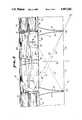
- FIG. 1is a bottom plan view of the troffer of the present invention showing a typical upper reflector system of a single cell and portions of a pair of adjacent cells in broken configuration.
- FIG. 2is a sectional view taken along line 2--2 of FIG. 1.
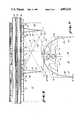
- FIG. 3is a sectional view taken along line 3--3 of FIG. 1 and includes ray lines depicting certain types of light distribution.
- FIG. 4is a bottom plan view of an alternate embodiment of the present invention, including a glare cut-off accessory.
- FIG. 5is a top, right, front, perspective of the glare cut-off accessory depicted in plan view in FIG. 4.
- FIG. 6is a sectional view taken along line 6--6 of FIG 4 illustrating ray lines representing the glare cut-off capabilities of the accessory depicted in FIGS. 4 and 5.
- FIG. 7is a sectional view taken along line 7--7 of FIG. 6.
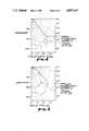
- FIG. 8is a graphical representation of the candle power distribution of the troffer of the present invention in the normal plane compared to the prior art 2 ⁇ 2 troffer.
- FIG. 9is a graphical representation, of the candle power distribution of the troffer of the present invention in the parallel plane compared to the prior art 2 ⁇ 2 troffer.
- lamp 32typically includes a pair of tubes 34 and 36 each having a diameter of 11/16 of an inch and lying between one another, center-to-center, about 3/4 of an inch. This leaves a gap of 1/8 of an inch between the tubes 34 and 36 and provides for an overall vertical height of one and one half inches.
- Lamp 32is oriented along a vertical axis 38 which is perpendicular to the floor or surface 40 (at nadir) being illuminated outwardly from troffer 10.
- lamp 32possesses an axis 42 of elongation which lies parallel to axes 44 and 46 of tubes 34 and 36, respectfully.
- Lamp 32may be of the Biax type, forty watt, manufactured by the General Electric Co., Schenectady, N.Y.
- Multiplicity of cells 13are formed by intersecting louvers such as louvers 48 and 50 being intersected by louvers 52 and 54 to form cell 22.
- Troffer 10includes additional louvers to form multiplicity of cells 13 in the same manner.
- FIG. 2depicts additional louvers 56 and 58.
- louvers 50, 52, 56 and 58 shown in FIG. 2include prior art parabolic reflecting surfaces such as surfaces 60 and 62 of louvers 48 and 50, respectfully.
- louvers 52 and 54include parabolic reflecting surfaces 64 and 66, respectfully, FIG. 3.
- plurality of louvers 47generally lie between surface 40 and lamp 32.
- baffle 102 depicted in its entiretyreveals an elongated base 106 having a pair of wings 108 and 110 extending upwardly at an obtuse angle from base 106.
- Side channels 112 and 114accommodate lamp tube 36.
- Such glare cut-offis very accurate in troffer 10 to reduce brightness or glare over 90% between 45° and 50° relative to the vertical axis 38.
- lightis very efficiently controlled in the "parallel" plane which is coincident with axes 42, 44, and 46 and also intersect surface 40 at generally a right angle.
- upper reflector system 12spreads light outwardly from troffer 10 toward the ends of tubes 34 and 36.
- ray line 122indicates the passage of direct light from lamp 32 escaping reflector by louver 54 up to an angle of 66° from axis 38, which represents the nadir.
- reflector portions 76C, 76D, 90C, and 90Dreflect light directly downwardly.
- Reflector portions 72, 74, 76A, 76B, 90A, and 90Bdo not provide lighting along axis 38.
- reflector portions 74, 76A, 76B, 90A, and 90Bproject light, by direct reflection from lamp 32 the intensity peaking at 25°-30° from nadir in the "normal" plane encompassing axis 68.
- Reflector portions 72 and 74also project light after interreflection.
- the image of the lampbegins to "ride off" reflector portions 74, 76A, 76B, 90A, and 90B until virtually no light is reflected from these reflector elements, at 35°.
- a peak of intensity of 35° from nadir in the normal planeis caused almost entirely by the light being reflected by transverse louvers, such as louvers 48 and 50. It should be noted that only a small section of reflector 72 provides light in the normal direction, FIG. 2.
- FIGS. 8 and 9depict a comparison of the heretofore described prior art 2 ⁇ 2 troffer with the bi-directional troffer 10 of the present invention.
- FIG. 8represents a plot of the "normal" plane encompassing axis 68.
- FIG. 9represents a plot of light projected in the "parallel" plane i.e. a plane encompassing axes 42, 44, and 46, FIG. 2.
- the troffer of the present inventionrepresents a significant improvement in light projection the parallel plane, graph line 130.
- the intensity of lighthas been increased below 55° as compared to prior art with maximum intensities between 15° and 35° to form the batwing curve which permits greater spacing ratios. Glare intensity, at angles over 55°, has been reduced from that of the prior art.
- the normal plane, graph line 128,shows the intensities peaking at 35° with no less efficiency than in the prior art and with reduced intensities at glare angle above 45°.
- the following examplerepresents the source of the data for FIGS. 8 and 9:
- the following candle power distributionwas obtained utilizing 2 ⁇ 2 troffer 10 of the present invention and a Leviton socket #26726 for a 9 cell unit.
- the lampswere rated at 3150 lumens each. Illuminance area was 21.3 ⁇ 7 feet.
- the lamps usedwere bias dual tube fluorescent lamps 221/2 inches in length manufactured by General Electric. The following measurements were acquired:
- the prior art 2 ⁇ 2 troffersmust be spaced no more then eight feet apart in this situation.
- the 2 ⁇ 2 troffer 10, of the present inventionachieves a fixture efficiency of approximately 74% with a specular parabolic louver and 72.9% with a semi-specular louver.
- the material of the upper reflector segmentsis highly specular and possess a reflectivity of 94%.
- the conventional prior art unitachieved only a 61.6% efficiency using a semi-specular louver and a conventional gloss white reflector with 88% reflectivity above the lamp.
- the same illuminationmay be produced with troffer 10 with 20% less fixtures, lamps and energy consumption than the prior art units (based on 8 ⁇ 10 foot spacing of prior art unit). If the prior art unit is placed on 8 ⁇ 8 foot spacing, comparitive energy usage for troffer 10 is less by approximately 36%.
- the Zonal Summary and Average Foot-Lamberts (Avg. FL) in the normal (NORM) and parallel (PARL) planesresults obtained utilizing the same lamps and 2 ⁇ 2 troffers depicted in Example I.
- the P-4 fluorescent fixtureincluded an 18 cell semi-specular louver, three F40T12 CW lamps, and advance ROM-2540-3-TP and HM-140-1-TP ballasts. All angles and zones are measured from nadir.
- troffer 10 of the present inventiononly permits 1.4% of lamp lumens to egress in the zone between 60° and 90°.
- 2 ⁇ 2 and 2 ⁇ 4 trofferspermitted 2.9% and 4.9% lamp lumens in the zones between 60% and 90% from nadir, respectively.
- the accessory baffles 102 and 104may be used as depicted in FIGS. 6 and 7 to intercept high angle rays (above 62° in the parallel direction), such as 134 and 136, representing glare light reflected from upper reflector system 12 and light directly emanating from lamp 32, respectively.
- ray 132, FIG. 6, from the lamp and upper reflector system 12is re-reflected from louver 54 to a non-glare angle.
- Such vigorous blocking of glareis sometimes necessary to prevent image obscuring reflections of the 2 ⁇ 2 troffer 10 on video display terminals. It has been found that use of baffles 102 and 104 reduces the overall efficiency of troffer 10 only by about 4%, an acceptable trade-off for the strict cut-off in the parallel plane.
Landscapes
- Engineering & Computer Science (AREA)
- General Engineering & Computer Science (AREA)
- Non-Portable Lighting Devices Or Systems Thereof (AREA)
Abstract
Description
______________________________________ MEASUREDCANDLEPOWER 2 × 2 TROFFER 10 PARA- NOR- DEGREE LLEL 22.5 45 67.5 MAL ______________________________________ 6 2910 2910 2910 2910 2910 5 2970 2931 2964 2922 2943 10 3012 2991 3000 3123 3168 15 3201 3072 3105 3264 3318 20 3471 3186 3123 3189 3180 25 3426 3207 3030 2970 2931 30 3285 3084 2904 3006 3141 35 3123 2988 2886 2248 3432 40 2952 2856 2886 3006 2733 45 2742 2478 2574 7148 1539 50 2253 1971 1551 381 138 55 1341 1383 528 75 57 60 528 657 72 48 54 65 275 112 39 39 36 70 21 12 12 6 6 75 9 6 6 3 3 80 3 3 3 3 3 85 3 3 0 0 0 90 0 0 0 0 0 ______________________________________
______________________________________ MEASURED CANDLEPOWERPRIOR ART 2 × 2 TROFFER PARA- NOR- DEGREE LLEL 22.5 45 67.5 MAL ______________________________________ 0 2559 2559 2559 2559 2559 5 2545 2550 2559 2566 2568 10 2498 2513 2550 2596 2611 15 2426 2453 2557 2678 2718 20 2335 2389 2581 2779 2855 25 2230 2328 2608 2915 3022 30 2102 2252 2648 2931 3019 35 1948 2157 2601 2791 2811 40 1772 2039 2371 2073 1686 45 1574 1874 1920 959 850 50 1348 1603 1025 667 658 55 1084 1184 569 499 503 60 803 731 377 338 334 65 396 279 194 156 128 70 55 51 54 31 28 75 24 22 19 18 15 80 13 12 10 9 9 85 4 4 4 3 3 90 0 0 0 0 0 ______________________________________
______________________________________ ZONAL SUMMARY AVG. FL. ZONE LUMENS LAMP FIXT. DEG PARL NORM ______________________________________ 2 × 2 TROFFER 10 0-30 873 27.7 37.4 0 2944 2944 0-40 1511 48.0 64.8 45 3923 2203 0-60 2290 72.7 98.3 55 2366 98 0-90 2333 74.1 100.0 65 (650)* 85 90-180 0 0.0 0.0 75 33 14 0-180 2333 74.1 100.0 85 26 10 PRIOR ART COLUMBIA LIGHTING P-4 2 × 2 TROFFER 0-30 2178 23.1 37.4 0 2561 2561 0-40 3788 39.0 63.2 45 2228 1204 0-60 5549 58.7 95.3 55 1892 878 0-90 5823 61.6 100.0 65 938 303 90-180 0 0.0 0.0 75 92 58 0-180 5923 61.6 100.0 85 51 34 PRIOR ART COLUMBIA LIGHTING P-4 2 × 4 TROFFER 0-30 2222 23.2 32.5 45 988 1110 0-40 3785 39.4 55.3 55 988 547 0-60 6365 66.3 93.1 65 611 201 0-90 6838 71.2 100.0 75 55 41 0-180 6838 71.2 100.0 85 20 20 ______________________________________ *approximate value
Claims (23)
Priority Applications (1)
| Application Number | Priority Date | Filing Date | Title |
|---|---|---|---|
| US07/273,093US4907143A (en) | 1988-11-18 | 1988-11-18 | Reflector system for fluorescent troffer |
Applications Claiming Priority (1)
| Application Number | Priority Date | Filing Date | Title |
|---|---|---|---|
| US07/273,093US4907143A (en) | 1988-11-18 | 1988-11-18 | Reflector system for fluorescent troffer |
Publications (1)
| Publication Number | Publication Date |
|---|---|
| US4907143Atrue US4907143A (en) | 1990-03-06 |
Family
ID=23042524
Family Applications (1)
| Application Number | Title | Priority Date | Filing Date |
|---|---|---|---|
| US07/273,093Expired - Fee RelatedUS4907143A (en) | 1988-11-18 | 1988-11-18 | Reflector system for fluorescent troffer |
Country Status (1)
| Country | Link |
|---|---|
| US (1) | US4907143A (en) |
Cited By (10)
| Publication number | Priority date | Publication date | Assignee | Title |
|---|---|---|---|---|
| EP0496920A1 (en)* | 1991-01-31 | 1992-08-05 | Siemens Aktiengesellschaft | Lighting fixture |
| US5264994A (en)* | 1991-03-21 | 1993-11-23 | Choi Yoong J | Recessed illuminating apparatus |
| US5394317A (en)* | 1992-11-03 | 1995-02-28 | Grenga; John J. | Lamp reflector |
| US5412551A (en)* | 1993-11-15 | 1995-05-02 | Mark Lighting Co., Inc. | Luminaire fixture |
| US5967648A (en)* | 1998-02-09 | 1999-10-19 | Lexalite International Corporation | Lighting fixture including a neutral density polymeric material for controlled light distribution |
| US20020096643A1 (en)* | 1996-02-08 | 2002-07-25 | Bright Solutions, Inc., A Michigan Corporation | Portable light source and system for use in leak detection |
| US6626560B1 (en)* | 2000-11-22 | 2003-09-30 | Ronald N. Caferro | Lighting louver |
| US9086521B2 (en) | 2011-04-14 | 2015-07-21 | Bright View Technologies Corporation | Light transmissive structures and fabrication methods for controlling far-field light distribution |
| US10317583B2 (en) | 2013-12-19 | 2019-06-11 | Bright View Technologies Corporation | 2D deglaring diffusers increasing axial luminous intensity |
| US20190346096A1 (en)* | 2016-09-29 | 2019-11-14 | Signify Holding B.V. | Core troffer lens-retainer with built in air functionality |
Citations (12)
| Publication number | Priority date | Publication date | Assignee | Title |
|---|---|---|---|---|
| US3591798A (en)* | 1968-11-04 | 1971-07-06 | Lightolier Inc | Lighting fixture |
| US4065667A (en)* | 1975-11-13 | 1977-12-27 | Donald L. Goulet | Indirect lighting fixture including improved reflector |
| US4384318A (en)* | 1980-12-24 | 1983-05-17 | Kidde Consumer Durables Corp. | Task light |
| US4562517A (en)* | 1983-02-28 | 1985-12-31 | Maximum Technology | Reflector systems for lighting fixtures and method of installation |
| US4575788A (en)* | 1984-04-30 | 1986-03-11 | Ql, Inc. | Segmented luminaire |
| US4617612A (en)* | 1985-01-22 | 1986-10-14 | Pritchett John C | High efficiency task lighting fixture |
| US4651260A (en)* | 1984-10-24 | 1987-03-17 | Prescolite Inc. | Roadway luminaire |
| US4683526A (en)* | 1985-11-06 | 1987-07-28 | Jac Jacobsen A/S | Asymmetric lamp |
| GB2190735A (en)* | 1986-06-06 | 1987-11-25 | Philips Electronic Associated | Light fitting |
| US4747027A (en)* | 1986-05-22 | 1988-05-24 | Friedhelm Hirt Leuchten | Fluorescent lamp light unit |
| US4760505A (en)* | 1987-05-04 | 1988-07-26 | Litecontrol Corporation | Indirect lighting fixture |
| EP0264857B1 (en)* | 1986-10-21 | 1991-01-16 | Siemens Aktiengesellschaft | Elongated lamp fixture for linear lighting |
- 1988
- 1988-11-18USUS07/273,093patent/US4907143A/ennot_activeExpired - Fee Related
Patent Citations (12)
| Publication number | Priority date | Publication date | Assignee | Title |
|---|---|---|---|---|
| US3591798A (en)* | 1968-11-04 | 1971-07-06 | Lightolier Inc | Lighting fixture |
| US4065667A (en)* | 1975-11-13 | 1977-12-27 | Donald L. Goulet | Indirect lighting fixture including improved reflector |
| US4384318A (en)* | 1980-12-24 | 1983-05-17 | Kidde Consumer Durables Corp. | Task light |
| US4562517A (en)* | 1983-02-28 | 1985-12-31 | Maximum Technology | Reflector systems for lighting fixtures and method of installation |
| US4575788A (en)* | 1984-04-30 | 1986-03-11 | Ql, Inc. | Segmented luminaire |
| US4651260A (en)* | 1984-10-24 | 1987-03-17 | Prescolite Inc. | Roadway luminaire |
| US4617612A (en)* | 1985-01-22 | 1986-10-14 | Pritchett John C | High efficiency task lighting fixture |
| US4683526A (en)* | 1985-11-06 | 1987-07-28 | Jac Jacobsen A/S | Asymmetric lamp |
| US4747027A (en)* | 1986-05-22 | 1988-05-24 | Friedhelm Hirt Leuchten | Fluorescent lamp light unit |
| GB2190735A (en)* | 1986-06-06 | 1987-11-25 | Philips Electronic Associated | Light fitting |
| EP0264857B1 (en)* | 1986-10-21 | 1991-01-16 | Siemens Aktiengesellschaft | Elongated lamp fixture for linear lighting |
| US4760505A (en)* | 1987-05-04 | 1988-07-26 | Litecontrol Corporation | Indirect lighting fixture |
Cited By (10)
| Publication number | Priority date | Publication date | Assignee | Title |
|---|---|---|---|---|
| EP0496920A1 (en)* | 1991-01-31 | 1992-08-05 | Siemens Aktiengesellschaft | Lighting fixture |
| US5264994A (en)* | 1991-03-21 | 1993-11-23 | Choi Yoong J | Recessed illuminating apparatus |
| US5394317A (en)* | 1992-11-03 | 1995-02-28 | Grenga; John J. | Lamp reflector |
| US5412551A (en)* | 1993-11-15 | 1995-05-02 | Mark Lighting Co., Inc. | Luminaire fixture |
| US20020096643A1 (en)* | 1996-02-08 | 2002-07-25 | Bright Solutions, Inc., A Michigan Corporation | Portable light source and system for use in leak detection |
| US5967648A (en)* | 1998-02-09 | 1999-10-19 | Lexalite International Corporation | Lighting fixture including a neutral density polymeric material for controlled light distribution |
| US6626560B1 (en)* | 2000-11-22 | 2003-09-30 | Ronald N. Caferro | Lighting louver |
| US9086521B2 (en) | 2011-04-14 | 2015-07-21 | Bright View Technologies Corporation | Light transmissive structures and fabrication methods for controlling far-field light distribution |
| US10317583B2 (en) | 2013-12-19 | 2019-06-11 | Bright View Technologies Corporation | 2D deglaring diffusers increasing axial luminous intensity |
| US20190346096A1 (en)* | 2016-09-29 | 2019-11-14 | Signify Holding B.V. | Core troffer lens-retainer with built in air functionality |
Similar Documents
| Publication | Publication Date | Title |
|---|---|---|
| US10323824B1 (en) | LED light fixture with light shaping features | |
| US5416684A (en) | Luminaire having predominantly refractive downlight capabilities | |
| US6505953B1 (en) | Luminaire optical system | |
| US4698734A (en) | Lensed indirect luminaire with side angle brightness control | |
| US4390930A (en) | Indirect lighting fixture with improved light control | |
| US7048416B2 (en) | Free-cavity, double-diffusing indirect lighting luminaire | |
| US4229782A (en) | High efficiency lighting units with beam cut-off angle | |
| US3591798A (en) | Lighting fixture | |
| US7585088B2 (en) | Fluorescent lamp fixture | |
| US5251116A (en) | Luminaire for creating a primary beam and a secondary beam | |
| CA1140903A (en) | Luminaire | |
| US20140268747A1 (en) | Standardized troffer fixture | |
| US8960958B1 (en) | Solid-state lighting troffer with readily retrofittable structure | |
| US4644454A (en) | Lensed indirect luminaire having improved light distribution control | |
| JPS61284003A (en) | indirect reflective lighting fixtures | |
| EP0514963B1 (en) | Line illumination device and mounting member for this device | |
| US6837592B1 (en) | Indirect luminaire optical system | |
| US4907143A (en) | Reflector system for fluorescent troffer | |
| AU677410B2 (en) | Luminaire | |
| US4748547A (en) | Uplight luminaire for achieving uniform illuminance across a ceiling | |
| US4975812A (en) | Indirect lighting fixture | |
| US5032959A (en) | Indirect luminaire with midpoint zoned imaging reflectors | |
| CA2175554C (en) | Indirect asymmetric luminaire assembly | |
| US6733154B1 (en) | Indirect luminaire | |
| US7029148B2 (en) | Luminaire having symmetrically opposed asymmetrical reflectors |
Legal Events
| Date | Code | Title | Description |
|---|---|---|---|
| AS | Assignment | Owner name:COLUMBIA LIGHTING, INC., N. 3808 SULLIVAN RD, SPOK Free format text:ASSIGNMENT OF ASSIGNORS INTEREST.;ASSIGNOR:LASKER, MARTIN L.;REEL/FRAME:004976/0050 Effective date:19881104 Owner name:COLUMBIA LIGHTING, INC., A DE. CORP., WASHINGTON Free format text:ASSIGNMENT OF ASSIGNORS INTEREST;ASSIGNOR:LASKER, MARTIN L.;REEL/FRAME:004976/0050 Effective date:19881104 | |
| REMI | Maintenance fee reminder mailed | ||
| LAPS | Lapse for failure to pay maintenance fees | ||
| FP | Lapsed due to failure to pay maintenance fee | Effective date:19940306 | |
| AS | Assignment | Owner name:WILMINGTON TRUST COMPANY, DELAWARE Free format text:SECURITY AGREEMENT;ASSIGNORS:AMES TRUE TEMPER PROPERTIES, INC;AMES TRUE TEMPER, INC;ARCHITECTURAL AREA LIGHTING, INC.;AND OTHERS;REEL/FRAME:011731/0097 Effective date:20010430 | |
| AS | Assignment | Owner name:PROGRESSIVE LIGHTING PROPERTIES, INC., FLORIDA Free format text:RELEASE OF SECURITY INTEREST IN INTELLECTUAL PROPERTY;ASSIGNOR:WILMINGTON TRUST COMPANY AS CORPORATE TRUSTEE;REEL/FRAME:015134/0225 Effective date:20030715 Owner name:PROGRESS LIGHTING, INC., FLORIDA Free format text:RELEASE OF SECURITY INTEREST IN INTELLECTUAL PROPERTY;ASSIGNOR:WILMINGTON TRUST COMPANY AS CORPORATE TRUSTEE;REEL/FRAME:015134/0225 Effective date:20030715 Owner name:SELKIRK CANADA U.S.A., INC., FLORIDA Free format text:RELEASE OF SECURITY INTEREST IN INTELLECTUAL PROPERTY;ASSIGNOR:WILMINGTON TRUST COMPANY AS CORPORATE TRUSTEE;REEL/FRAME:015134/0225 Effective date:20030715 Owner name:ENVIRONMENTAL ENERGY COMPANY, FLORIDA Free format text:RELEASE OF SECURITY INTEREST IN INTELLECTUAL PROPERTY;ASSIGNOR:WILMINGTON TRUST COMPANY AS CORPORATE TRUSTEE;REEL/FRAME:015134/0225 Effective date:20030715 Owner name:MOBILITE INC., FLORIDA Free format text:RELEASE OF SECURITY INTEREST IN INTELLECTUAL PROPERTY;ASSIGNOR:WILMINGTON TRUST COMPANY AS CORPORATE TRUSTEE;REEL/FRAME:015134/0225 Effective date:20030715 Owner name:JUSI HOLDINGS, INC., FLORIDA Free format text:RELEASE OF SECURITY INTEREST IN INTELLECTUAL PROPERTY;ASSIGNOR:WILMINGTON TRUST COMPANY AS CORPORATE TRUSTEE;REEL/FRAME:015134/0225 Effective date:20030715 Owner name:LOKELANI DEVELOPMENT CORPORATION, FLORIDA Free format text:RELEASE OF SECURITY INTEREST IN INTELLECTUAL PROPERTY;ASSIGNOR:WILMINGTON TRUST COMPANY AS CORPORATE TRUSTEE;REEL/FRAME:015134/0225 Effective date:20030715 Owner name:USI CAPITAL, INC., FLORIDA Free format text:RELEASE OF SECURITY INTEREST IN INTELLECTUAL PROPERTY;ASSIGNOR:WILMINGTON TRUST COMPANY AS CORPORATE TRUSTEE;REEL/FRAME:015134/0225 Effective date:20030715 Owner name:KLI, INC., FLORIDA Free format text:RELEASE OF SECURITY INTEREST IN INTELLECTUAL PROPERTY;ASSIGNOR:WILMINGTON TRUST COMPANY AS CORPORATE TRUSTEE;REEL/FRAME:015134/0225 Effective date:20030715 Owner name:NEPCO OF AUSTRALIA, INC., FLORIDA Free format text:RELEASE OF SECURITY INTEREST IN INTELLECTUAL PROPERTY;ASSIGNOR:WILMINGTON TRUST COMPANY AS CORPORATE TRUSTEE;REEL/FRAME:015134/0225 Effective date:20030715 Owner name:LUXOR INDUSRIES, INC., FLORIDA Free format text:RELEASE OF SECURITY INTEREST IN INTELLECTUAL PROPERTY;ASSIGNOR:WILMINGTON TRUST COMPANY AS CORPORATE TRUSTEE;REEL/FRAME:015134/0225 Effective date:20030715 Owner name:USI AMERICAN HOLDINGS, INC., FLORIDA Free format text:RELEASE OF SECURITY INTEREST IN INTELLECTUAL PROPERTY;ASSIGNOR:WILMINGTON TRUST COMPANY AS CORPORATE TRUSTEE;REEL/FRAME:015134/0225 Effective date:20030715 Owner name:LIGHTING CORPORATION OF AMERICA, INC., FLORIDA Free format text:RELEASE OF SECURITY INTEREST IN INTELLECTUAL PROPERTY;ASSIGNOR:WILMINGTON TRUST COMPANY AS CORPORATE TRUSTEE;REEL/FRAME:015134/0225 Effective date:20030715 Owner name:PROGRESSIVE LIGHTING, INC. (SC), FLORIDA Free format text:RELEASE OF SECURITY INTEREST IN INTELLECTUAL PROPERTY;ASSIGNOR:WILMINGTON TRUST COMPANY AS CORPORATE TRUSTEE;REEL/FRAME:015134/0225 Effective date:20030715 Owner name:COLUMBIA LIGHTING-LCA, INC., FLORIDA Free format text:RELEASE OF SECURITY INTEREST IN INTELLECTUAL PROPERTY;ASSIGNOR:WILMINGTON TRUST COMPANY AS CORPORATE TRUSTEE;REEL/FRAME:015134/0225 Effective date:20030715 Owner name:AMES TRUE TEMPER, INC., FLORIDA Free format text:RELEASE OF SECURITY INTEREST IN INTELLECTUAL PROPERTY;ASSIGNOR:WILMINGTON TRUST COMPANY AS CORPORATE TRUSTEE;REEL/FRAME:015134/0225 Effective date:20030715 Owner name:SELKIRK EUROPE U.S.A., INC., FLORIDA Free format text:RELEASE OF SECURITY INTEREST IN INTELLECTUAL PROPERTY;ASSIGNOR:WILMINGTON TRUST COMPANY AS CORPORATE TRUSTEE;REEL/FRAME:015134/0225 Effective date:20030715 Owner name:JACUZZI INC., FLORIDA Free format text:RELEASE OF SECURITY INTEREST IN INTELLECTUAL PROPERTY;ASSIGNOR:WILMINGTON TRUST COMPANY AS CORPORATE TRUSTEE;REEL/FRAME:015134/0225 Effective date:20030715 Owner name:PH PROPERTY DEVELOPMENT COMPANY, FLORIDA Free format text:RELEASE OF SECURITY INTEREST IN INTELLECTUAL PROPERTY;ASSIGNOR:WILMINGTON TRUST COMPANY AS CORPORATE TRUSTEE;REEL/FRAME:015134/0225 Effective date:20030715 Owner name:SELKIRK, INC., FLORIDA Free format text:RELEASE OF SECURITY INTEREST IN INTELLECTUAL PROPERTY;ASSIGNOR:WILMINGTON TRUST COMPANY AS CORPORATE TRUSTEE;REEL/FRAME:015134/0225 Effective date:20030715 Owner name:UGE LIQUIDATION INC., FLORIDA Free format text:RELEASE OF SECURITY INTEREST IN INTELLECTUAL PROPERTY;ASSIGNOR:WILMINGTON TRUST COMPANY AS CORPORATE TRUSTEE;REEL/FRAME:015134/0225 Effective date:20030715 Owner name:USI ATLANTIC CORP., FLORIDA Free format text:RELEASE OF SECURITY INTEREST IN INTELLECTUAL PROPERTY;ASSIGNOR:WILMINGTON TRUST COMPANY AS CORPORATE TRUSTEE;REEL/FRAME:015134/0225 Effective date:20030715 Owner name:MAILIKAI LAND DEVELOPMENT CORPORATION, FLORIDA Free format text:RELEASE OF SECURITY INTEREST IN INTELLECTUAL PROPERTY;ASSIGNOR:WILMINGTON TRUST COMPANY AS CORPORATE TRUSTEE;REEL/FRAME:015134/0225 Effective date:20030715 Owner name:HL CAPITAL CORP., FLORIDA Free format text:RELEASE OF SECURITY INTEREST IN INTELLECTUAL PROPERTY;ASSIGNOR:WILMINGTON TRUST COMPANY AS CORPORATE TRUSTEE;REEL/FRAME:015134/0225 Effective date:20030715 Owner name:SUNDANCE SPAS, INC., FLORIDA Free format text:RELEASE OF SECURITY INTEREST IN INTELLECTUAL PROPERTY;ASSIGNOR:WILMINGTON TRUST COMPANY AS CORPORATE TRUSTEE;REEL/FRAME:015134/0225 Effective date:20030715 Owner name:TA LIQUIDATION CORP., FLORIDA Free format text:RELEASE OF SECURITY INTEREST IN INTELLECTUAL PROPERTY;ASSIGNOR:WILMINGTON TRUST COMPANY AS CORPORATE TRUSTEE;REEL/FRAME:015134/0225 Effective date:20030715 Owner name:GARY CONCRETE PRODUCTS, INC., FLORIDA Free format text:RELEASE OF SECURITY INTEREST IN INTELLECTUAL PROPERTY;ASSIGNOR:WILMINGTON TRUST COMPANY AS CORPORATE TRUSTEE;REEL/FRAME:015134/0225 Effective date:20030715 Owner name:LCA GROUP INC., FLORIDA Free format text:RELEASE OF SECURITY INTEREST IN INTELLECTUAL PROPERTY;ASSIGNOR:WILMINGTON TRUST COMPANY AS CORPORATE TRUSTEE;REEL/FRAME:015134/0225 Effective date:20030715 Owner name:DUAL-LITE MANUFACTURING, INC., FLORIDA Free format text:RELEASE OF SECURITY INTEREST IN INTELLECTUAL PROPERTY;ASSIGNOR:WILMINGTON TRUST COMPANY AS CORPORATE TRUSTEE;REEL/FRAME:015134/0225 Effective date:20030715 Owner name:TRIMFOOT CO., FLORIDA Free format text:RELEASE OF SECURITY INTEREST IN INTELLECTUAL PROPERTY;ASSIGNOR:WILMINGTON TRUST COMPANY AS CORPORATE TRUSTEE;REEL/FRAME:015134/0225 Effective date:20030715 Owner name:PROGRESSIVE LIGHTING, INC. (NC), FLORIDA Free format text:RELEASE OF SECURITY INTEREST IN INTELLECTUAL PROPERTY;ASSIGNOR:WILMINGTON TRUST COMPANY AS CORPORATE TRUSTEE;REEL/FRAME:015134/0225 Effective date:20030715 Owner name:JACUZZI WHIRLPOOL BATH, INC., FLORIDA Free format text:RELEASE OF SECURITY INTEREST IN INTELLECTUAL PROPERTY;ASSIGNOR:WILMINGTON TRUST COMPANY AS CORPORATE TRUSTEE;REEL/FRAME:015134/0225 Effective date:20030715 Owner name:KIM LIGHTING INC., FLORIDA Free format text:RELEASE OF SECURITY INTEREST IN INTELLECTUAL PROPERTY;ASSIGNOR:WILMINGTON TRUST COMPANY AS CORPORATE TRUSTEE;REEL/FRAME:015134/0225 Effective date:20030715 Owner name:REDMONT, INC., FLORIDA Free format text:RELEASE OF SECURITY INTEREST IN INTELLECTUAL PROPERTY;ASSIGNOR:WILMINGTON TRUST COMPANY AS CORPORATE TRUSTEE;REEL/FRAME:015134/0225 Effective date:20030715 Owner name:NEPCO OF CANADA, INC., FLORIDA Free format text:RELEASE OF SECURITY INTEREST IN INTELLECTUAL PROPERTY;ASSIGNOR:WILMINGTON TRUST COMPANY AS CORPORATE TRUSTEE;REEL/FRAME:015134/0225 Effective date:20030715 Owner name:AMES TRUE TEMPER PROPRETIES, INC., FLORIDA Free format text:RELEASE OF SECURITY INTEREST IN INTELLECTUAL PROPERTY;ASSIGNOR:WILMINGTON TRUST COMPANY AS CORPORATE TRUSTEE;REEL/FRAME:015134/0225 Effective date:20030715 Owner name:PRESCOLITE LITE CONTROLS, INC., FLORIDA Free format text:RELEASE OF SECURITY INTEREST IN INTELLECTUAL PROPERTY;ASSIGNOR:WILMINGTON TRUST COMPANY AS CORPORATE TRUSTEE;REEL/FRAME:015134/0225 Effective date:20030715 Owner name:GATSBY SPAS, INC., FLORIDA Free format text:RELEASE OF SECURITY INTEREST IN INTELLECTUAL PROPERTY;ASSIGNOR:WILMINGTON TRUST COMPANY AS CORPORATE TRUSTEE;REEL/FRAME:015134/0225 Effective date:20030715 Owner name:SANITARY-DASH MANUFACTURING CO. INC., FLORIDA Free format text:RELEASE OF SECURITY INTEREST IN INTELLECTUAL PROPERTY;ASSIGNOR:WILMINGTON TRUST COMPANY AS CORPORATE TRUSTEE;REEL/FRAME:015134/0225 Effective date:20030715 Owner name:EZ HOLDING, INC., FLORIDA Free format text:RELEASE OF SECURITY INTEREST IN INTELLECTUAL PROPERTY;ASSIGNOR:WILMINGTON TRUST COMPANY AS CORPORATE TRUSTEE;REEL/FRAME:015134/0225 Effective date:20030715 Owner name:ZURN EPC SERVICES, INC., FLORIDA Free format text:RELEASE OF SECURITY INTEREST IN INTELLECTUAL PROPERTY;ASSIGNOR:WILMINGTON TRUST COMPANY AS CORPORATE TRUSTEE;REEL/FRAME:015134/0225 Effective date:20030715 Owner name:SPAULDING LIGHTING, INC., FLORIDA Free format text:RELEASE OF SECURITY INTEREST IN INTELLECTUAL PROPERTY;ASSIGNOR:WILMINGTON TRUST COMPANY AS CORPORATE TRUSTEE;REEL/FRAME:015134/0225 Effective date:20030715 Owner name:U.S. INDUSTRIES, INC., FLORIDA Free format text:RELEASE OF SECURITY INTEREST IN INTELLECTUAL PROPERTY;ASSIGNOR:WILMINGTON TRUST COMPANY AS CORPORATE TRUSTEE;REEL/FRAME:015134/0225 Effective date:20030715 Owner name:LCA (NS) INC., FLORIDA Free format text:RELEASE OF SECURITY INTEREST IN INTELLECTUAL PROPERTY;ASSIGNOR:WILMINGTON TRUST COMPANY AS CORPORATE TRUSTEE;REEL/FRAME:015134/0225 Effective date:20030715 Owner name:ZURNACQ OF CALIFORNIA, INC., FLORIDA Free format text:RELEASE OF SECURITY INTEREST IN INTELLECTUAL PROPERTY;ASSIGNOR:WILMINGTON TRUST COMPANY AS CORPORATE TRUSTEE;REEL/FRAME:015134/0225 Effective date:20030715 Owner name:UNITED STATES BRASS CORP., FLORIDA Free format text:RELEASE OF SECURITY INTEREST IN INTELLECTUAL PROPERTY;ASSIGNOR:WILMINGTON TRUST COMPANY AS CORPORATE TRUSTEE;REEL/FRAME:015134/0225 Effective date:20030715 Owner name:ZURN GOLF HOLDING CORPORATION, FLORIDA Free format text:RELEASE OF SECURITY INTEREST IN INTELLECTUAL PROPERTY;ASSIGNOR:WILMINGTON TRUST COMPANY AS CORPORATE TRUSTEE;REEL/FRAME:015134/0225 Effective date:20030715 Owner name:ZURN INDUSTRIES, INC., FLORIDA Free format text:RELEASE OF SECURITY INTEREST IN INTELLECTUAL PROPERTY;ASSIGNOR:WILMINGTON TRUST COMPANY AS CORPORATE TRUSTEE;REEL/FRAME:015134/0225 Effective date:20030715 Owner name:TT LIQUIDATION CORP., FLORIDA Free format text:RELEASE OF SECURITY INTEREST IN INTELLECTUAL PROPERTY;ASSIGNOR:WILMINGTON TRUST COMPANY AS CORPORATE TRUSTEE;REEL/FRAME:015134/0225 Effective date:20030715 Owner name:STRATEGIC CAPITAL MANAGEMENT, INC., FLORIDA Free format text:RELEASE OF SECURITY INTEREST IN INTELLECTUAL PROPERTY;ASSIGNOR:WILMINGTON TRUST COMPANY AS CORPORATE TRUSTEE;REEL/FRAME:015134/0225 Effective date:20030715 Owner name:USI FUNDING, INC., FLORIDA Free format text:RELEASE OF SECURITY INTEREST IN INTELLECTUAL PROPERTY;ASSIGNOR:WILMINGTON TRUST COMPANY AS CORPORATE TRUSTEE;REEL/FRAME:015134/0225 Effective date:20030715 Owner name:NEPCO OF FULTON, INC., FLORIDA Free format text:RELEASE OF SECURITY INTEREST IN INTELLECTUAL PROPERTY;ASSIGNOR:WILMINGTON TRUST COMPANY AS CORPORATE TRUSTEE;REEL/FRAME:015134/0225 Effective date:20030715 Owner name:USI GLOBAL CORP., FLORIDA Free format text:RELEASE OF SECURITY INTEREST IN INTELLECTUAL PROPERTY;ASSIGNOR:WILMINGTON TRUST COMPANY AS CORPORATE TRUSTEE;REEL/FRAME:015134/0225 Effective date:20030715 Owner name:ARCHITECTURAL AREA LIGHTING, INC., FLORIDA Free format text:RELEASE OF SECURITY INTEREST IN INTELLECTUAL PROPERTY;ASSIGNOR:WILMINGTON TRUST COMPANY AS CORPORATE TRUSTEE;REEL/FRAME:015134/0225 Effective date:20030715 Owner name:ARROW CONSOLIDATED CORPORATION, FLORIDA Free format text:RELEASE OF SECURITY INTEREST IN INTELLECTUAL PROPERTY;ASSIGNOR:WILMINGTON TRUST COMPANY AS CORPORATE TRUSTEE;REEL/FRAME:015134/0225 Effective date:20030715 Owner name:ZURN DEVCO, INC., FLORIDA Free format text:RELEASE OF SECURITY INTEREST IN INTELLECTUAL PROPERTY;ASSIGNOR:WILMINGTON TRUST COMPANY AS CORPORATE TRUSTEE;REEL/FRAME:015134/0225 Effective date:20030715 Owner name:BATHCRAFT INC., FLORIDA Free format text:RELEASE OF SECURITY INTEREST IN INTELLECTUAL PROPERTY;ASSIGNOR:WILMINGTON TRUST COMPANY AS CORPORATE TRUSTEE;REEL/FRAME:015134/0225 Effective date:20030715 Owner name:BRUCKNER MANUFACTURING COP., FLORIDA Free format text:RELEASE OF SECURITY INTEREST IN INTELLECTUAL PROPERTY;ASSIGNOR:WILMINGTON TRUST COMPANY AS CORPORATE TRUSTEE;REEL/FRAME:015134/0225 Effective date:20030715 Owner name:PRESCOLITE, INC., FLORIDA Free format text:RELEASE OF SECURITY INTEREST IN INTELLECTUAL PROPERTY;ASSIGNOR:WILMINGTON TRUST COMPANY AS CORPORATE TRUSTEE;REEL/FRAME:015134/0225 Effective date:20030715 Owner name:ASTERIA COMPANY, FLORIDA Free format text:RELEASE OF SECURITY INTEREST IN INTELLECTUAL PROPERTY;ASSIGNOR:WILMINGTON TRUST COMPANY AS CORPORATE TRUSTEE;REEL/FRAME:015134/0225 Effective date:20030715 Owner name:BAYLIS BROTHERS, INC., FLORIDA Free format text:RELEASE OF SECURITY INTEREST IN INTELLECTUAL PROPERTY;ASSIGNOR:WILMINGTON TRUST COMPANY AS CORPORATE TRUSTEE;REEL/FRAME:015134/0225 Effective date:20030715 Owner name:COLUBMIA LIGHTING PROPERTIES, INC., FLORIDA Free format text:RELEASE OF SECURITY INTEREST IN INTELLECTUAL PROPERTY;ASSIGNOR:WILMINGTON TRUST COMPANY AS CORPORATE TRUSTEE;REEL/FRAME:015134/0225 Effective date:20030715 Owner name:NEPCO OF PAKISTAN, INC., FLORIDA Free format text:RELEASE OF SECURITY INTEREST IN INTELLECTUAL PROPERTY;ASSIGNOR:WILMINGTON TRUST COMPANY AS CORPORATE TRUSTEE;REEL/FRAME:015134/0225 Effective date:20030715 Owner name:IXL MANUFACTURING COMPANY, INC., FLORIDA Free format text:RELEASE OF SECURITY INTEREST IN INTELLECTUAL PROPERTY;ASSIGNOR:WILMINGTON TRUST COMPANY AS CORPORATE TRUSTEE;REEL/FRAME:015134/0225 Effective date:20030715 Owner name:NEPCO OF FORD HIGHTS, INC., FLORIDA Free format text:RELEASE OF SECURITY INTEREST IN INTELLECTUAL PROPERTY;ASSIGNOR:WILMINGTON TRUST COMPANY AS CORPORATE TRUSTEE;REEL/FRAME:015134/0225 Effective date:20030715 Owner name:COLUMBIA LIGHTING MFG., INC., FLORIDA Free format text:RELEASE OF SECURITY INTEREST IN INTELLECTUAL PROPERTY;ASSIGNOR:WILMINGTON TRUST COMPANY AS CORPORATE TRUSTEE;REEL/FRAME:015134/0225 Effective date:20030715 Owner name:COLUMBIA LIGHTING, INC., FLORIDA Free format text:RELEASE OF SECURITY INTEREST IN INTELLECTUAL PROPERTY;ASSIGNOR:WILMINGTON TRUST COMPANY AS CORPORATE TRUSTEE;REEL/FRAME:015134/0225 Effective date:20030715 Owner name:OUTDOOR PRODUCTS LLC, FLORIDA Free format text:RELEASE OF SECURITY INTEREST IN INTELLECTUAL PROPERTY;ASSIGNOR:WILMINGTON TRUST COMPANY AS CORPORATE TRUSTEE;REEL/FRAME:015134/0225 Effective date:20030715 Owner name:NISSEN UNIVERSAL HOLDINGS INC., FLORIDA Free format text:RELEASE OF SECURITY INTEREST IN INTELLECTUAL PROPERTY;ASSIGNOR:WILMINGTON TRUST COMPANY AS CORPORATE TRUSTEE;REEL/FRAME:015134/0225 Effective date:20030715 Owner name:COLUMBIA MATERIALS, LLC, FLORIDA Free format text:RELEASE OF SECURITY INTEREST IN INTELLECTUAL PROPERTY;ASSIGNOR:WILMINGTON TRUST COMPANY AS CORPORATE TRUSTEE;REEL/FRAME:015134/0225 Effective date:20030715 Owner name:STREAMWOOD CORPORATION, FLORIDA Free format text:RELEASE OF SECURITY INTEREST IN INTELLECTUAL PROPERTY;ASSIGNOR:WILMINGTON TRUST COMPANY AS CORPORATE TRUSTEE;REEL/FRAME:015134/0225 Effective date:20030715 Owner name:USI PROPERTIES, INC., FLORIDA Free format text:RELEASE OF SECURITY INTEREST IN INTELLECTUAL PROPERTY;ASSIGNOR:WILMINGTON TRUST COMPANY AS CORPORATE TRUSTEE;REEL/FRAME:015134/0225 Effective date:20030715 Owner name:ZURN CONSTRUCTORS, INC., FLORIDA Free format text:RELEASE OF SECURITY INTEREST IN INTELLECTUAL PROPERTY;ASSIGNOR:WILMINGTON TRUST COMPANY AS CORPORATE TRUSTEE;REEL/FRAME:015134/0225 Effective date:20030715 Owner name:CARLSBAD CORP., FLORIDA Free format text:RELEASE OF SECURITY INTEREST IN INTELLECTUAL PROPERTY;ASSIGNOR:WILMINGTON TRUST COMPANY AS CORPORATE TRUSTEE;REEL/FRAME:015134/0225 Effective date:20030715 Owner name:COMPAX CORP., FLORIDA Free format text:RELEASE OF SECURITY INTEREST IN INTELLECTUAL PROPERTY;ASSIGNOR:WILMINGTON TRUST COMPANY AS CORPORATE TRUSTEE;REEL/FRAME:015134/0225 Effective date:20030715 Owner name:ZURCO, INC., FLORIDA Free format text:RELEASE OF SECURITY INTEREST IN INTELLECTUAL PROPERTY;ASSIGNOR:WILMINGTON TRUST COMPANY AS CORPORATE TRUSTEE;REEL/FRAME:015134/0225 Effective date:20030715 Owner name:ELJER INDUSTRIES, INC., FLORIDA Free format text:RELEASE OF SECURITY INTEREST IN INTELLECTUAL PROPERTY;ASSIGNOR:WILMINGTON TRUST COMPANY AS CORPORATE TRUSTEE;REEL/FRAME:015134/0225 Effective date:20030715 Owner name:ELJER PLUMBINGWARE, INC., FLORIDA Free format text:RELEASE OF SECURITY INTEREST IN INTELLECTUAL PROPERTY;ASSIGNOR:WILMINGTON TRUST COMPANY AS CORPORATE TRUSTEE;REEL/FRAME:015134/0225 Effective date:20030715 Owner name:ZURN (CAYMAN ISLANDS), INC., FLORIDA Free format text:RELEASE OF SECURITY INTEREST IN INTELLECTUAL PROPERTY;ASSIGNOR:WILMINGTON TRUST COMPANY AS CORPORATE TRUSTEE;REEL/FRAME:015134/0225 Effective date:20030715 Owner name:DUAL-LITE INC., FLORIDA Free format text:RELEASE OF SECURITY INTEREST IN INTELLECTUAL PROPERTY;ASSIGNOR:WILMINGTON TRUST COMPANY AS CORPORATE TRUSTEE;REEL/FRAME:015134/0225 Effective date:20030715 Owner name:USI REALTY CORP., FLORIDA Free format text:RELEASE OF SECURITY INTEREST IN INTELLECTUAL PROPERTY;ASSIGNOR:WILMINGTON TRUST COMPANY AS CORPORATE TRUSTEE;REEL/FRAME:015134/0225 Effective date:20030715 | |
| STCH | Information on status: patent discontinuation | Free format text:PATENT EXPIRED DUE TO NONPAYMENT OF MAINTENANCE FEES UNDER 37 CFR 1.362 |