US4907004A - Power versatile satellite transmitter - Google Patents
Power versatile satellite transmitterDownload PDFInfo
- Publication number
- US4907004A US4907004AUS07/197,328US19732888AUS4907004AUS 4907004 AUS4907004 AUS 4907004AUS 19732888 AUS19732888 AUS 19732888AUS 4907004 AUS4907004 AUS 4907004A
- Authority
- US
- United States
- Prior art keywords
- hybrid matrix
- power amplifier
- input
- ports
- radiating elements
- Prior art date
- Legal status (The legal status is an assumption and is not a legal conclusion. Google has not performed a legal analysis and makes no representation as to the accuracy of the status listed.)
- Expired - Fee Related
Links
Images


Classifications
- H—ELECTRICITY
- H01—ELECTRIC ELEMENTS
- H01Q—ANTENNAS, i.e. RADIO AERIALS
- H01Q3/00—Arrangements for changing or varying the orientation or the shape of the directional pattern of the waves radiated from an antenna or antenna system
- H01Q3/26—Arrangements for changing or varying the orientation or the shape of the directional pattern of the waves radiated from an antenna or antenna system varying the relative phase or relative amplitude of energisation between two or more active radiating elements; varying the distribution of energy across a radiating aperture
- H01Q3/30—Arrangements for changing or varying the orientation or the shape of the directional pattern of the waves radiated from an antenna or antenna system varying the relative phase or relative amplitude of energisation between two or more active radiating elements; varying the distribution of energy across a radiating aperture varying the relative phase between the radiating elements of an array
- H01Q3/34—Arrangements for changing or varying the orientation or the shape of the directional pattern of the waves radiated from an antenna or antenna system varying the relative phase or relative amplitude of energisation between two or more active radiating elements; varying the distribution of energy across a radiating aperture varying the relative phase between the radiating elements of an array by electrical means
- H01Q3/40—Arrangements for changing or varying the orientation or the shape of the directional pattern of the waves radiated from an antenna or antenna system varying the relative phase or relative amplitude of energisation between two or more active radiating elements; varying the distribution of energy across a radiating aperture varying the relative phase between the radiating elements of an array by electrical means with phasing matrix
Definitions
- This inventionrelates to satellite communications and, more particularly, to an improved transmitter section of a communications satellite.
- a fundamental requirement of the design of communications satellitesis the efficient use of the available RF power. This requirement becomes even more important in the design of power intensive mobile satellite systems.
- Such mobile systemsuse low gain omni antennas on the mobile and require a high EIRP (effective isotropically radiated power) and G/T (gain/temperature ratio) on the satellite to provide satisfactory performance.
- This performanceis obtained by means of high gain spot beams on the spacecraft with area coverage obtained with multiple spot beams. Since the traffic density is non-uniform on the ground some beams will carry more traffic and require more power than other beams. Because the traffic distribution is expected to vary with time and may not be known before the satellite is launched, it is very desirable to be able to move power from one beam to another, while the satellite is in orbit, to maximize the use of the spacecraft resources.
- An important spacecraft parameteris the minimum antenna gain at the cross over point between beam. This gain is maximized if the distance between beam centers is kept small and is normally accomplished by a beam forming network followed by a separate power amplifier driving each antenna radiating element. This allows each beam to be formed by a cluster of elements with the cluster for adjacent beams sharing some of the elements. Such a system has no capability of moving power from one beam to another unless a complicated switching system is implemented.
- a low level beam forming network followed by the power amplifiershas an additional penalty when the amplifiers are unequally loaded.
- the phase and gain performance of a power amplifierdepend upon the operating power level of the amplifier. Thus if amplifiers driving different elements of a beam cluster have different power levels, because some amplifiers carry signals for adjacent beams, the phase and amplitude at the antenna radiating elements will depart from ideal causing a loss in antenna gain.
- This inventiondescribes how the concept of overlapping feed clusters can be combined with the hybrid matrix transponder thus maximizing the antenna gain at the cross-over point while retaining flexible power distribution capability.
- the present inventionsucceeds in providing both optimum overall coverage area gain and almost unlimited power assignment flexibility. It does this by succeeding to combine the following two powerful design techniques:
- the inventionprovides an overlapping beam, power versatile system for a communications satellite, comprising a low level beam forming network having inputs to which a plurality of individual beam signals are respectively applied, the beam forming network having a plurality of outputs, some of which respectively carry the sum of components of more than one input signal, a hybrid matrix power amplifier having input ports respectively connected to the outputs of the low level beam forming network and having complementary output ports respectively connected to a plurality of radiating elements of the same number as the outputs of the beam forming network, the manner in which the beam signals are combined within the beam forming network, the connections between the outputs of the beam forming network and the input ports of the hybrid matrix power amplifier and the connections between the output ports of the hybrid matrix power amplifier and the radiating elements being determined to achieve equal power amplifier loading and to achieve beam overlap.
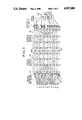
- FIG. 1shows schematically the basics of a system according to the invention
- FIG. 2shows how coherent signal phases are selected at the power amplifiers in the system of FIG. 1;
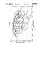
- FIG. 3is a diagram similar to FIG. 1 but involving the use of many more beams.
- FIG. 4illustrates the antenna coverage obtained by the system of FIG. 3.
- the system shown in FIG. 1is a simplified hypothetical 3 beam system.
- a low level beam forming network (LLBFN) 10has three input ports and four output ports interconnected by couplers 12. Three beam signals each having a unique frequency are applied, respectively to the three input ports of LLBFN 10.
- the couplers 12are arranged so as to divide the beam signals each into two components and then combine selected ones of the individual signal components into a single output port. Specifically, it will be understood by tracing the signal paths from the three inputs to LLBFN outputs 1, 2, 3 and 4 that only a portion of signal 1 appears at output 1, portions of signals 1 and 2 appear at output 2, portions of signals 2 and 3 appear at output 3 and only a portion of signal 3 appears at output 4.
- the two signal components of each beamare independently phased and level adjusted within the LLBFN 10 so as to reach the output ports at the same phase and level. What the LLBFN achieves then is to process the original beam signals into an arrangement whereby signals from two beams can be combined into a common radiating element. The co-existence of two beam signals on a single radiating element generates beam overlap at that point.
- the outputs from the LLBFN 10are appropriately connected to the input ports of a hybrid matrix Power Amplifier (HMPA) 14 the functions of which are described below.
- HMPAhybrid matrix Power Amplifier
- the hybrid matrix power amplifier 14comprises a 4 ⁇ 4 input hybrid matrix 16 feeding a power amplifier section 18 which in turn feeds a 4 ⁇ 4 output hybrid matrix 20 which is identical to matrix 16.
- the power amplifier section 18comprises individual amplifiers (PA) 22 respectively connected between each output port of matrix 16 and the corresponding input port of matrix 20.
- the output ports of matrix 20are connected respectively to four radiating elements 24 in a particular manner described below.
- the radiating elements 24, which may be horns or other types of radiator,are clustered about the focal point of a parabolic reflector 26. The fact that the radiating elements 24 are positioned at different physical locations with respect to the reflector focal point gives rise to the formation of separate beams.
- the hybrid matrix for this type of applicationconsists of 90 degree, 3 dB hybrids.
- the properties of the matrixare such that:
- the output phases of the signal corresponding to each of the input ports of the input matrix 16are presented in FIG. 2.
- the indicated phase valuesassume equal paths of interconnecting transmission lines between hybrids.
- the implied positive phase anglehas no significance in this analysis since it is only the phase difference which is important.
- each PA 22would see an average power loading equal to the arithmetic sum of the four power components associated with the input ports.
- loadingmight not be uniform across all PA's 22. For example, if two equal signals at matrix input ports 1 and 4 were coherent and had the same phase, complete signal cancellation would have taken place at PA's 1 and 4 while in PA's 2 and 3 two in-phase components would have generated twice the average loading. Maintaining equal or as nearly equal as possible loading on the PA's 22 in the presence of coherent signals is the essence of this invention.
- Equal PA loadingimplies that the smallest, lightest and most power efficient PA can be used for a given application. Major cost savings can result from this, mainly due to lower mass and power requirements on the spacecraft bus and partly due to lower production costs of a smaller PA unit.
- the radiating elements 24 numbered upwardly from the bottom as 1, 2, 3 and 4are connected to the output ports of output matrix as follows: radiating element 1 is connected to port 3, radiating element 2 is connected to port 1, radiating element 3 is connected to port 2 and radiating element 4 is connected to port 4.
- radiating elements 1 and 2are connected to input ports 3 and 1, respectively of input matrix 16.
- all of beam signal 1is radiated as beam B1 from radiating elements 1 and 2.
- radiating elements 2 and 3are effectively supplied by ports 1 and 2 of input matrix 16 meaning that these two radiating elements radiate beam B2 carrying all of beam signal 2.
- radiating elements 3 and 4radiate a beam B3 which carries all of beam signal 3.
- RF power assignment flexibilityis one of the key properties of the hybrid matrix PA.
- a signal applied to any input portis divided equally across the PA's and summed again at the complementary output port.
- the amount of power taken from the PA's by such signalcan be varied arbitrarily from zero to the combined maximum of all the PA's.
- the same degree of power assignment flexibilitycan be provided in the case of beam forming signals going through the matrix PA as long as the coherence problem has been addressed as in the example of FIG. 1.
- Power assignment with beam forming signalshas, of course, significance only on a beam basis. By varying the beam drive level more or less power is assigned to that beam.
- the system of FIG. 3consists of eleven overlapping beams and employs unequal power split between the feed elements of a beam. Selection of valid matrix port combinations and fitting of valid combinations to generate the desired system beam pattern is done by appropriate computer programs. (See Appendix A attached hereto.)
- a cluster of fourteen radiating elements 24'is used to generate the eleven beams.
- the radiating elements 24'are positioned as appropriate with reference to the focal point of the antenna reflector (not shown).
- the input and output hybrid matrices 16' and 18'are each 16 port hybrids rather than the 4 port hybrids shown in FIGS. 1 and 2. Two of the ports (namely 9 and 13) have no input signal applied to them and, therefore, no output signal obtained therefrom.
- the LLBFN 10'has eleven input ports and fourteen output ports interconnected by couplers 12'. It is noted that, as in the generalized configuration of FIG. 1, the number of radiating elements 24' is the same as the number of output ports of LLBFN 10'.
- FIG. 3illustrates the use of output filters 30 which, although not a part of the inventive concept, are essential to the operation of a real system.
- Such filtersalthough not shown in FIG. 1, would be present in a practical system.
- the developed computer programshelp with the selection of the most uniform loading configurations. With some judicious choice of feed elements per beam and beam power split over these feed elements per beam the key advantages of this concept can be maintained essentially intact.
- the individual componentssuch as the LLBFN and the HMPA, could be implemented in different forms without affecting the inventive concept.
- Particular illustrative examplesare (a) discrete coaxial components interconnected with detachable cables, (b) stripline construction with all couplers and lines continuously laid out, (c) discrete waveguide components and (d) continuous TEM line box assembly.
- the radiating elementscould, for example, be in the form of (a) waveguide horns, (b) cross dipole horns, (c) helices and (d) patch radiators and could be circular, square or have another shape of aperture.
- the number of radiating elementsexceeds the number of beams, this need not necessarily be so and, for example, a four beam system could be implemented using three radiating elements.
- the ratio of beams to radiating elementsdepends on the amount of overlap, the complexity of the coverage area and possibly the electrical size (number of wavelengths) of the radiating elements.
- each radiating element 24 or 24'could in reality be constituted by a pair of radiating elements (or even more) both located at approximately the same position with reference to the antenna focal point.
- Appendix Acomprises three technical memoranda, 600-03 entitled OPTIMUM INPUT GROUPINGS OF THE HYBRID MATRIX AMPLIFIER, 600-05 entitled DETERMINATION OF MATRIX AMPLIFIER INPUT COMBINATIONS and 600-06 entitled OPTIMUM INPUT GROUPINGS OF THE HYBRID MATRIX AMPLIFIER FOR UNEQUAL INPUT VOLTAGES.
Landscapes
- Radio Relay Systems (AREA)
- Variable-Direction Aerials And Aerial Arrays (AREA)
Abstract
Description
Claims (11)
Priority Applications (1)
| Application Number | Priority Date | Filing Date | Title |
|---|---|---|---|
| US07/197,328US4907004A (en) | 1988-05-23 | 1988-05-23 | Power versatile satellite transmitter |
Applications Claiming Priority (1)
| Application Number | Priority Date | Filing Date | Title |
|---|---|---|---|
| US07/197,328US4907004A (en) | 1988-05-23 | 1988-05-23 | Power versatile satellite transmitter |
Publications (1)
| Publication Number | Publication Date |
|---|---|
| US4907004Atrue US4907004A (en) | 1990-03-06 |
Family
ID=22728950
Family Applications (1)
| Application Number | Title | Priority Date | Filing Date |
|---|---|---|---|
| US07/197,328Expired - Fee RelatedUS4907004A (en) | 1988-05-23 | 1988-05-23 | Power versatile satellite transmitter |
Country Status (1)
| Country | Link |
|---|---|
| US (1) | US4907004A (en) |
Cited By (36)
| Publication number | Priority date | Publication date | Assignee | Title |
|---|---|---|---|---|
| US5034752A (en)* | 1989-07-04 | 1991-07-23 | Thomson Csf | Multiple-beam antenna system with active modules and digital beam-forming |
| US5038150A (en)* | 1990-05-14 | 1991-08-06 | Hughes Aircraft Company | Feed network for a dual circular and dual linear polarization antenna |
| US5430452A (en)* | 1990-06-19 | 1995-07-04 | Thomson-Csf | Device for supply to the radiating elements of an array antenna, and application thereof to an antenna of an MLS type landing system |
| US5604462A (en)* | 1995-11-17 | 1997-02-18 | Lucent Technologies Inc. | Intermodulation distortion detection in a power shared amplifier network |
| WO1997023017A1 (en)* | 1995-12-15 | 1997-06-26 | Telefonaktiebolaget Lm Ericsson (Publ) | Antenna assembly and associated method for radio communication device |
| US5646631A (en)* | 1995-12-15 | 1997-07-08 | Lucent Technologies Inc. | Peak power reduction in power sharing amplifier networks |
| WO1998008321A1 (en)* | 1996-08-19 | 1998-02-26 | Motorola Inc. | Apparatus and method for providing a beacon signal in a wireless communication system |
| US5734345A (en)* | 1996-04-23 | 1998-03-31 | Trw Inc. | Antenna system for controlling and redirecting communications beams |
| WO1998013950A1 (en)* | 1996-09-24 | 1998-04-02 | Motorola Inc. | Apparatus and method for providing wireless communication to a sectorized coverage area |
| US5745077A (en)* | 1996-06-17 | 1998-04-28 | Das; Satyendranath | High efficiency satellite equally loaded transmitting communication system |
| US5751250A (en)* | 1995-10-13 | 1998-05-12 | Lucent Technologies, Inc. | Low distortion power sharing amplifier network |
| US5760741A (en)* | 1996-04-09 | 1998-06-02 | Trw Inc. | Beam forming network for multiple-beam-feed sharing antenna system |
| US5784030A (en)* | 1996-06-06 | 1998-07-21 | Hughes Electronics Corporation | Calibration method for satellite communications payloads using hybrid matrices |
| US5812088A (en)* | 1994-12-19 | 1998-09-22 | Agence Spatiale Europeenne | Beam forming network for radiofrequency antennas |
| US5818388A (en)* | 1996-06-06 | 1998-10-06 | Hughes Electronics Corporation | Satellite communications apparatus using active redundancy |
| EP0877444A1 (en)* | 1997-05-05 | 1998-11-11 | Nortel Networks Corporation | Downlink beam forming architecture for heavily overlapped beam configuration |
| US5854611A (en)* | 1995-07-24 | 1998-12-29 | Lucent Technologies Inc. | Power shared linear amplifier network |
| US5859610A (en)* | 1994-06-16 | 1999-01-12 | Alcatel N.V. | Method and a system for locating ground equipment transmitting via satellites |
| RU2155460C2 (en)* | 1995-03-29 | 2000-08-27 | Телефонактиеболагет Лм Эрикссон (Пабл) | Antenna with wide lobe of directivity pattern |
| US6173155B1 (en)* | 1997-10-17 | 2001-01-09 | Hughes Electronics Corporation | Method and apparatus for spacecraft amplification of multi-channel signals |
| EP0963005A3 (en)* | 1998-06-05 | 2001-03-28 | Hughes Electronics Corporation | Reconfigurable multiple beam satellite reflector antenna with an array feed |
| US6243038B1 (en)* | 1998-12-17 | 2001-06-05 | Metawave Communications Corporation | System and method providing amplification of narrow band signals with multi-channel amplifiers |
| US6259899B1 (en)* | 1998-11-04 | 2001-07-10 | Hughes Electrical Corporation | System and method for analysis of intermodulation dispersion |
| US6445343B1 (en) | 2000-02-16 | 2002-09-03 | Hughes Electronics Corporation | Antenna element array alignment system |
| US6633551B1 (en)* | 1999-09-29 | 2003-10-14 | Lockheed Martin Corporation | High-rel beacon signal sequencer |
| US6650281B2 (en)* | 2000-07-06 | 2003-11-18 | Alcatel | Telecommunications antenna intended to cover a large terrestrial area |
| US6670918B2 (en)* | 2001-06-21 | 2003-12-30 | Alcatel | Method of repointing a reflector array antenna |
| WO2004025774A3 (en)* | 2002-09-11 | 2009-06-18 | Lockheed Corp | Partly interleaved phased arrays with different antenna elements in central and outer region |
| JP2011139268A (en)* | 2009-12-28 | 2011-07-14 | Fujitsu Ltd | Wireless relay apparatus, and wireless relay method |
| US20110189948A1 (en)* | 2010-02-03 | 2011-08-04 | Viasat, Inc. | Flexible coverage areas for forward link signals in a spot beam satellite communication system |
| CN102556368A (en)* | 2010-12-07 | 2012-07-11 | 波音公司 | Power management scheme for protecting components on board a spacecraft |
| US20150009069A1 (en)* | 2013-07-05 | 2015-01-08 | Electronics And Telecommunications Research Institute | Multi-beam antenna system and method for controlling output power thereof |
| US9848370B1 (en)* | 2015-03-16 | 2017-12-19 | Rkf Engineering Solutions Llc | Satellite beamforming |
| US10284308B1 (en) | 2017-12-06 | 2019-05-07 | Space Systems/Loral, Llc | Satellite system calibration in active operational channels |
| US10320349B1 (en) | 2017-12-06 | 2019-06-11 | Space Systems/Loral, Llc | Multiport amplifier input network with compensation for output network gain and phase frequency response imbalance |
| US10361762B2 (en) | 2017-12-06 | 2019-07-23 | Space Systems/Loral, Llc | Calibration of satellite beamforming channels |
Citations (3)
| Publication number | Priority date | Publication date | Assignee | Title |
|---|---|---|---|---|
| US4414550A (en)* | 1981-08-04 | 1983-11-08 | The Bendix Corporation | Low profile circular array antenna and microstrip elements therefor |
| US4638317A (en)* | 1984-06-19 | 1987-01-20 | Westinghouse Electric Corp. | Orthogonal beam forming network |
| US4652879A (en)* | 1985-02-11 | 1987-03-24 | Eaton Corporation | Phased array antenna system to produce wide-open coverage of a wide angular sector with high directive gain and strong capability to resolve multiple signals |
- 1988
- 1988-05-23USUS07/197,328patent/US4907004A/ennot_activeExpired - Fee Related
Patent Citations (3)
| Publication number | Priority date | Publication date | Assignee | Title |
|---|---|---|---|---|
| US4414550A (en)* | 1981-08-04 | 1983-11-08 | The Bendix Corporation | Low profile circular array antenna and microstrip elements therefor |
| US4638317A (en)* | 1984-06-19 | 1987-01-20 | Westinghouse Electric Corp. | Orthogonal beam forming network |
| US4652879A (en)* | 1985-02-11 | 1987-03-24 | Eaton Corporation | Phased array antenna system to produce wide-open coverage of a wide angular sector with high directive gain and strong capability to resolve multiple signals |
Non-Patent Citations (2)
| Title |
|---|
| "An Adaptive Multiple Beam System Concept", IEEE Journal of Selected Areas in Communications, vol. SAC-4, No. 5, May 1987, by Egami and Kawai. |
| An Adaptive Multiple Beam System Concept , IEEE Journal of Selected Areas in Communications , vol. SAC 4, No. 5, May 1987, by Egami and Kawai.* |
Cited By (55)
| Publication number | Priority date | Publication date | Assignee | Title |
|---|---|---|---|---|
| US5034752A (en)* | 1989-07-04 | 1991-07-23 | Thomson Csf | Multiple-beam antenna system with active modules and digital beam-forming |
| JPH0787414B2 (en) | 1990-05-14 | 1995-09-20 | ヒューズ・エアクラフト・カンパニー | Supply network for dual circular polarization and dual linear polarization antennas |
| US5038150A (en)* | 1990-05-14 | 1991-08-06 | Hughes Aircraft Company | Feed network for a dual circular and dual linear polarization antenna |
| EP0457500A3 (en)* | 1990-05-14 | 1992-06-10 | Hughes Aircraft Company | Dual linear and dual circular polarization antenna |
| US5430452A (en)* | 1990-06-19 | 1995-07-04 | Thomson-Csf | Device for supply to the radiating elements of an array antenna, and application thereof to an antenna of an MLS type landing system |
| US5859610A (en)* | 1994-06-16 | 1999-01-12 | Alcatel N.V. | Method and a system for locating ground equipment transmitting via satellites |
| US5812088A (en)* | 1994-12-19 | 1998-09-22 | Agence Spatiale Europeenne | Beam forming network for radiofrequency antennas |
| RU2155460C2 (en)* | 1995-03-29 | 2000-08-27 | Телефонактиеболагет Лм Эрикссон (Пабл) | Antenna with wide lobe of directivity pattern |
| US5854611A (en)* | 1995-07-24 | 1998-12-29 | Lucent Technologies Inc. | Power shared linear amplifier network |
| US5751250A (en)* | 1995-10-13 | 1998-05-12 | Lucent Technologies, Inc. | Low distortion power sharing amplifier network |
| US5604462A (en)* | 1995-11-17 | 1997-02-18 | Lucent Technologies Inc. | Intermodulation distortion detection in a power shared amplifier network |
| WO1997023017A1 (en)* | 1995-12-15 | 1997-06-26 | Telefonaktiebolaget Lm Ericsson (Publ) | Antenna assembly and associated method for radio communication device |
| US5646631A (en)* | 1995-12-15 | 1997-07-08 | Lucent Technologies Inc. | Peak power reduction in power sharing amplifier networks |
| AU708284B2 (en)* | 1995-12-15 | 1999-07-29 | Telefonaktiebolaget Lm Ericsson (Publ) | Antenna assembly and associated method for radio communication device |
| US5924020A (en)* | 1995-12-15 | 1999-07-13 | Telefonaktiebolaget L M Ericsson (Publ) | Antenna assembly and associated method for radio communication device |
| JP3046941B2 (en) | 1996-04-09 | 2000-05-29 | ティアールダブリュー インコーポレイテッド | Beamforming networks for multi-beam fed shared antenna systems |
| US5760741A (en)* | 1996-04-09 | 1998-06-02 | Trw Inc. | Beam forming network for multiple-beam-feed sharing antenna system |
| US5734345A (en)* | 1996-04-23 | 1998-03-31 | Trw Inc. | Antenna system for controlling and redirecting communications beams |
| US5818388A (en)* | 1996-06-06 | 1998-10-06 | Hughes Electronics Corporation | Satellite communications apparatus using active redundancy |
| US5784030A (en)* | 1996-06-06 | 1998-07-21 | Hughes Electronics Corporation | Calibration method for satellite communications payloads using hybrid matrices |
| EP0812072A3 (en)* | 1996-06-06 | 2004-04-14 | Hughes Electronics Corporation | Satellite communications apparatus using active redundancy |
| US5745077A (en)* | 1996-06-17 | 1998-04-28 | Das; Satyendranath | High efficiency satellite equally loaded transmitting communication system |
| WO1998008321A1 (en)* | 1996-08-19 | 1998-02-26 | Motorola Inc. | Apparatus and method for providing a beacon signal in a wireless communication system |
| US5805575A (en)* | 1996-08-19 | 1998-09-08 | Motorola, Inc. | Apparatus and method for providing a beacon signal in a wireless communication system |
| US5825762A (en)* | 1996-09-24 | 1998-10-20 | Motorola, Inc. | Apparatus and methods for providing wireless communication to a sectorized coverage area |
| CN1111974C (en)* | 1996-09-24 | 2003-06-18 | 摩托罗拉公司 | Apparatus and method for providing wireless communication to a sector-shaped coverage area |
| GB2322264A (en)* | 1996-09-24 | 1998-08-19 | Motorola Inc | Apparatus and method for providing wireless communication to a sectorized coverage area |
| WO1998013950A1 (en)* | 1996-09-24 | 1998-04-02 | Motorola Inc. | Apparatus and method for providing wireless communication to a sectorized coverage area |
| KR100299773B1 (en)* | 1996-09-24 | 2001-09-06 | 비센트 비.인그라시아, 알크 엠 아헨 | Apparatus and method for providing wireless communication to a sectorized coverage area |
| GB2322264B (en)* | 1996-09-24 | 2001-03-14 | Motorola Inc | Apparatus and method for providing wireless communication to a sectorized coverage area |
| US6104935A (en)* | 1997-05-05 | 2000-08-15 | Nortel Networks Corporation | Down link beam forming architecture for heavily overlapped beam configuration |
| EP0877444A1 (en)* | 1997-05-05 | 1998-11-11 | Nortel Networks Corporation | Downlink beam forming architecture for heavily overlapped beam configuration |
| US6173155B1 (en)* | 1997-10-17 | 2001-01-09 | Hughes Electronics Corporation | Method and apparatus for spacecraft amplification of multi-channel signals |
| EP0963005A3 (en)* | 1998-06-05 | 2001-03-28 | Hughes Electronics Corporation | Reconfigurable multiple beam satellite reflector antenna with an array feed |
| US6259899B1 (en)* | 1998-11-04 | 2001-07-10 | Hughes Electrical Corporation | System and method for analysis of intermodulation dispersion |
| US6243038B1 (en)* | 1998-12-17 | 2001-06-05 | Metawave Communications Corporation | System and method providing amplification of narrow band signals with multi-channel amplifiers |
| US6633551B1 (en)* | 1999-09-29 | 2003-10-14 | Lockheed Martin Corporation | High-rel beacon signal sequencer |
| US6445343B1 (en) | 2000-02-16 | 2002-09-03 | Hughes Electronics Corporation | Antenna element array alignment system |
| US6650281B2 (en)* | 2000-07-06 | 2003-11-18 | Alcatel | Telecommunications antenna intended to cover a large terrestrial area |
| US6670918B2 (en)* | 2001-06-21 | 2003-12-30 | Alcatel | Method of repointing a reflector array antenna |
| WO2004025774A3 (en)* | 2002-09-11 | 2009-06-18 | Lockheed Corp | Partly interleaved phased arrays with different antenna elements in central and outer region |
| JP2011139268A (en)* | 2009-12-28 | 2011-07-14 | Fujitsu Ltd | Wireless relay apparatus, and wireless relay method |
| US20110189948A1 (en)* | 2010-02-03 | 2011-08-04 | Viasat, Inc. | Flexible coverage areas for forward link signals in a spot beam satellite communication system |
| US8494445B2 (en)* | 2010-02-03 | 2013-07-23 | Viasat, Inc. | Flexible coverage areas for forward link signals in a spot beam satellite communication system |
| CN102556368B (en)* | 2010-12-07 | 2016-08-10 | 波音公司 | The Power management scheme of on-board components on protection spacecraft |
| CN102556368A (en)* | 2010-12-07 | 2012-07-11 | 波音公司 | Power management scheme for protecting components on board a spacecraft |
| US8792822B2 (en) | 2010-12-07 | 2014-07-29 | The Boeing Company | Power management scheme for protecting components on board a spacecraft |
| US20150009069A1 (en)* | 2013-07-05 | 2015-01-08 | Electronics And Telecommunications Research Institute | Multi-beam antenna system and method for controlling output power thereof |
| US9774384B2 (en)* | 2013-07-05 | 2017-09-26 | Electronics And Telecommunications Research Institute | Multi-beam antenna system and method for controlling output power thereof |
| US9848370B1 (en)* | 2015-03-16 | 2017-12-19 | Rkf Engineering Solutions Llc | Satellite beamforming |
| US10555236B1 (en)* | 2015-03-16 | 2020-02-04 | Rkf Engineering Solutions Llc | Satellite beamforming |
| US10284308B1 (en) | 2017-12-06 | 2019-05-07 | Space Systems/Loral, Llc | Satellite system calibration in active operational channels |
| US10320349B1 (en) | 2017-12-06 | 2019-06-11 | Space Systems/Loral, Llc | Multiport amplifier input network with compensation for output network gain and phase frequency response imbalance |
| US10361762B2 (en) | 2017-12-06 | 2019-07-23 | Space Systems/Loral, Llc | Calibration of satellite beamforming channels |
| US10673399B2 (en) | 2017-12-06 | 2020-06-02 | Space Systems/Loral, Llc | Multiport amplifier input network with compensation for output network gain and phase frequency response imbalance |
Similar Documents
| Publication | Publication Date | Title |
|---|---|---|
| US4907004A (en) | Power versatile satellite transmitter | |
| US4901085A (en) | Divided LLBFN/HMPA transmitted architecture | |
| US5151706A (en) | Apparatus for electronically controlling the radiation pattern of an antenna having one or more beams of variable width and/or direction | |
| US5115248A (en) | Multibeam antenna feed device | |
| US4814775A (en) | Reconfigurable beam-forming network that provides in-phase power to each region | |
| EP0756762B1 (en) | Antenna system | |
| CN101803113B (en) | System for simplification of reconfigurable beam-forming network processing within a phased array antenna for a telecommunications satellite | |
| EP3213371B1 (en) | Antenna apparatus supporting adjustability of an antenna beam direction | |
| US8427370B2 (en) | Methods and apparatus for multiple beam aperture | |
| EP0600715B1 (en) | Active transmit phased array antenna | |
| CN1879254B (en) | Phased array antenna system with controllable electrical tilt | |
| US8451172B2 (en) | Reconfigurable beam-forming-network architecture | |
| CN106602265B (en) | Beam forming network and input structure, input and output method and three-beam antenna thereof | |
| US6897829B2 (en) | Phased array antenna providing gradual changes in beam steering and beam reconfiguration and related methods | |
| US4451831A (en) | Circular array scanning network | |
| JPH11127021A (en) | Multi-beam phased array antenna system | |
| US6295026B1 (en) | Enhanced direct radiating array | |
| CN116318278B (en) | Multi-beam forming network and six-beam base station antenna | |
| US5548295A (en) | Multishaped beam direct radiating array antenna | |
| KR20010072866A (en) | One-dimensional interleaved multi-beam antenna | |
| US4949092A (en) | Modularized contoured beam direct radiating antenna | |
| CN115567147A (en) | Radio interference system | |
| Tugend et al. | Hybrid beamforming with reduced grating lobes for satellite applications | |
| US6255990B1 (en) | Processor for two-dimensional array antenna | |
| EP0786826A2 (en) | Intermodulation scattering communications apparatus |
Legal Events
| Date | Code | Title | Description |
|---|---|---|---|
| AS | Assignment | Owner name:SPAR AEROSPACE LIMITED, 6303 AIRPORT ROAD, SUITE 4 Free format text:ASSIGNMENT OF ASSIGNORS INTEREST.;ASSIGNORS:ZACHARATOS, JOHN;WILLIAMSON, ROBERT B.;REEL/FRAME:004928/0587 Effective date:19880810 Owner name:SPAR AEROSPACE LIMITED,CANADA Free format text:ASSIGNMENT OF ASSIGNORS INTEREST;ASSIGNORS:ZACHARATOS, JOHN;WILLIAMSON, ROBERT B.;REEL/FRAME:004928/0587 Effective date:19880810 | |
| FEPP | Fee payment procedure | Free format text:PAYOR NUMBER ASSIGNED (ORIGINAL EVENT CODE: ASPN); ENTITY STATUS OF PATENT OWNER: LARGE ENTITY | |
| FPAY | Fee payment | Year of fee payment:4 | |
| FEPP | Fee payment procedure | Free format text:PAYER NUMBER DE-ASSIGNED (ORIGINAL EVENT CODE: RMPN); ENTITY STATUS OF PATENT OWNER: LARGE ENTITY Free format text:PAYOR NUMBER ASSIGNED (ORIGINAL EVENT CODE: ASPN); ENTITY STATUS OF PATENT OWNER: LARGE ENTITY | |
| AS | Assignment | Owner name:BANK OF NOVA SCOTIA, THE, CANADA Free format text:SECURITY INTEREST;ASSIGNOR:SPAR AEROSPACE LIMITED;REEL/FRAME:008495/0439 Effective date:19970415 | |
| FPAY | Fee payment | Year of fee payment:8 | |
| AS | Assignment | Owner name:EMS TECHNOLOGIES CANADA, LTD., CANADA Free format text:ASSIGNMENT OF ASSIGNORS INTEREST;ASSIGNOR:SPAR AEROSPACE LIMITED;REEL/FRAME:010164/0297 Effective date:19990730 | |
| REMI | Maintenance fee reminder mailed | ||
| LAPS | Lapse for failure to pay maintenance fees | ||
| STCH | Information on status: patent discontinuation | Free format text:PATENT EXPIRED DUE TO NONPAYMENT OF MAINTENANCE FEES UNDER 37 CFR 1.362 | |
| FP | Lapsed due to failure to pay maintenance fee | Effective date:20020306 |