US4905909A - Fluidic oscillating nozzle - Google Patents
Fluidic oscillating nozzleDownload PDFInfo
- Publication number
- US4905909A US4905909AUS07/092,186US9218687AUS4905909AUS 4905909 AUS4905909 AUS 4905909AUS 9218687 AUS9218687 AUS 9218687AUS 4905909 AUS4905909 AUS 4905909A
- Authority
- US
- United States
- Prior art keywords
- jet
- nozzle
- fluidic
- fluid
- interaction region
- Prior art date
- Legal status (The legal status is an assumption and is not a legal conclusion. Google has not performed a legal analysis and makes no representation as to the accuracy of the status listed.)
- Expired - Lifetime
Links
Images


Classifications
- B—PERFORMING OPERATIONS; TRANSPORTING
- B05—SPRAYING OR ATOMISING IN GENERAL; APPLYING FLUENT MATERIALS TO SURFACES, IN GENERAL
- B05B—SPRAYING APPARATUS; ATOMISING APPARATUS; NOZZLES
- B05B1/00—Nozzles, spray heads or other outlets, with or without auxiliary devices such as valves, heating means
- B05B1/02—Nozzles, spray heads or other outlets, with or without auxiliary devices such as valves, heating means designed to produce a jet, spray, or other discharge of particular shape or nature, e.g. in single drops, or having an outlet of particular shape
- B05B1/08—Nozzles, spray heads or other outlets, with or without auxiliary devices such as valves, heating means designed to produce a jet, spray, or other discharge of particular shape or nature, e.g. in single drops, or having an outlet of particular shape of pulsating nature, e.g. delivering liquid in successive separate quantities
- F—MECHANICAL ENGINEERING; LIGHTING; HEATING; WEAPONS; BLASTING
- F15—FLUID-PRESSURE ACTUATORS; HYDRAULICS OR PNEUMATICS IN GENERAL
- F15C—FLUID-CIRCUIT ELEMENTS PREDOMINANTLY USED FOR COMPUTING OR CONTROL PURPOSES
- F15C1/00—Circuit elements having no moving parts
- F15C1/22—Oscillators
- Y—GENERAL TAGGING OF NEW TECHNOLOGICAL DEVELOPMENTS; GENERAL TAGGING OF CROSS-SECTIONAL TECHNOLOGIES SPANNING OVER SEVERAL SECTIONS OF THE IPC; TECHNICAL SUBJECTS COVERED BY FORMER USPC CROSS-REFERENCE ART COLLECTIONS [XRACs] AND DIGESTS
- Y10—TECHNICAL SUBJECTS COVERED BY FORMER USPC
- Y10T—TECHNICAL SUBJECTS COVERED BY FORMER US CLASSIFICATION
- Y10T137/00—Fluid handling
- Y10T137/206—Flow affected by fluid contact, energy field or coanda effect [e.g., pure fluid device or system]
- Y10T137/212—System comprising plural fluidic devices or stages
- Y10T137/2125—Plural power inputs [e.g., parallel inputs]
- Y10T137/2147—To cascaded plural devices
- Y10T137/2153—With feedback passage[s] between devices of cascade
- Y—GENERAL TAGGING OF NEW TECHNOLOGICAL DEVELOPMENTS; GENERAL TAGGING OF CROSS-SECTIONAL TECHNOLOGIES SPANNING OVER SEVERAL SECTIONS OF THE IPC; TECHNICAL SUBJECTS COVERED BY FORMER USPC CROSS-REFERENCE ART COLLECTIONS [XRACs] AND DIGESTS
- Y10—TECHNICAL SUBJECTS COVERED BY FORMER USPC
- Y10T—TECHNICAL SUBJECTS COVERED BY FORMER US CLASSIFICATION
- Y10T137/00—Fluid handling
- Y10T137/206—Flow affected by fluid contact, energy field or coanda effect [e.g., pure fluid device or system]
- Y10T137/2229—Device including passages having V over T configuration
- Y10T137/2234—And feedback passage[s] or path[s]
Definitions
- This inventionrelates to nozzles that disperse a fluid or fluids to a surface for cleaning, washing, blasting, or allied processes in which fluid impact with the surface is important.
- these nozzleshave the ability to provide a spray over a large area with a liquid droplet size larger than conventional fan-type nozzles having the same pressure and flow. Consequently, a spray over a large area with low overspray and atomization is obtained.
- pressurized fluidsthere has been long-term interest in the use of pressurized fluids to impact surfaces.
- An example of one such application of pressurized fluidsis the use of pressurized water for cleaning and washing of cars, trucks, industrial equipment, floors, driveways, and buildings.
- any cleaning operationthere are three functions to be performed: (1) the application of water or water and chemicals to soak dirt and film on the surface to be cleaned (soaking function), (2) the removal of dirt and film by the impact of the water jet (removal function), and (3) the application of water for rinsing the cleaned surface (rinsing function).
- the relative relationships between water pressure, velocity, flow rate, and impact energyare proportional: the higher the pressure, the higher the velocity; the higher the velocity, the higher the flow rate; the higher the velocity and flow rate, the higher the impact energy.
- the impact energy actually generateddepends on the area of the surface impacted. This relationship between the impact energy and the area to be cleaned may be termed the impact energy density. To achieve a higher impact energy density, either the velocity and flow rate must be increased or the area impacted must be decreased.
- the flow rate of waterIn the soaking and rinsing functions, the flow rate of water, and thus the velocity and water pressure, must be sufficiently large to apply the necessary amount of water to cover the surface to be cleaned and to do so in a given amount of time. Particularly for the rinsing function, there is a minimum flow rate that is efficient in terms of time and water usage.
- the water pressuremust be sufficiently large to project the water to the surface to be cleaned at a high velocity so that the impact energy of the water will be sufficient to dislodge dirt and other particles to perform the removal function.
- a balance between the flow rate and the impact energyFor water usage to be the most economical, a balance between the flow rate and the impact energy must be achieved. This balance must also be taken into account for each of the three cleaning functions.
- the fan-type nozzleuses a small opening to limit the flow rate and expand the jet over a large area.
- the small openingcauses the jet to break up into small droplets.
- the velocity of these dropletsdecreases as they impact the air. This decreased velocity means that the fan-type jet has a low impact energy.
- the impact energy densityis low.
- a zero-degree jetis a jet that does not expand radially with respect to the direction of travel as it is projected from the nozzle. Because the droplets in a zero-degree jet follow the same path, the effects of air drag are decreased and the jet retains much more of its initial velocity than does a fan-type jet. Thus, the impact energy of a zero-degree jet is larger than that of a fan-type jet for two reasons.
- a zero-degree jetimpacts a smaller area, and thus, the impact energy density of a zero-degree jet is larger than that of a fan-type jet.
- the aerodynamic dragaffects the fan-type jet more, the fan-type jet loses its momentum more drastically as a function of distance travelled. Consequently, the zero-degree ]et produces a larger impact energy and a larger impact energy density than a fan-type jet.
- pressurized fluidsAnother use of pressurized fluids is the application of chemicals such as insecticides and herbicides to a selected area.
- chemicalssuch as insecticides and herbicides
- itis important to direct the chemicals to the target area with a minimum of direct overspray or atomization of liquid to avoid susceptibility to drift. Consequently, in addition to requiring high pressure (for distance) and low flow, this application requires large droplet size which is inconsistent with that provided by conventional fan-type nozzle configurations.
- Both techniques for injecting upstream and downstream of the main mechanical pumpare sought to enhance cleaning effectiveness.
- the object of the later techniqueis to introduce such chemicals directly into the oscillating jet to avoid damage to the pump and cavitation.
- Still another object of the inventionis to minimize overspray and maximize the reach of the fluid stream.
- a fluidic oscillating nozzlecomprising a supply port connected to a primary fluid flow passage converging to a throat, a nozzle, and control means.
- These elementsmay be connected to a fluidic oscillator comprising a pressure source connected to a secondary fluid flow passage converging to a throat, nozzle means, an interaction region including inlet and outlet openings, and feedback passages originating at receivers and terminating at control ports.
- the interaction regionmay be vented or unvented to the surrounding atmosphere.
- the interaction regionmay be connected to a venturi jet pump comprising a plenum area and fluid flow chamber comprising a converging-diverging venturi, and a suction inlet jet.
- a fluid flow control valvemay be connected to the venturi jet pump. Cleaning chemicals or other fluids may be introduced at the suction inlet jet.
- FIG. 1illustrates a fluidic jet-deflection amplifying device
- FIG. 2illustrates a fluidic oscillator with feedback that provides pressure oscillation
- FIG. 3illustrates the fluidic device that comprises the present invention, a fluidic oscillating nozzle
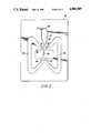
- FIG. 4illustrates the flow pattern of the oscillating jet as it issues from the fluidic oscillating nozzle
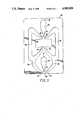
- FIG. 5illustrates the configuration of a venturi jet pump that may be used to create suction to inject fluids into the jet stream
- FIG. 6illustrates a schematic of an embodiment of the present invention with soap or chemical injector means positioned upstream of the main mechanical pump.
- the jet issuing from the fluidic oscillating nozzleis a coherent zero-degree jet that has a high impact energy density and moves in a sweeping pattern to cover a large area.
- the jethas the appearance of a fan-type jet.
- FIG. 1illustrates a preferred embodiment of a deflected-jet fluidic nozzle 10 which may be utilized as the second stage of the two-stage system of the present invention.
- Nozzle 10has an output nozzle 28 so as to form a zero-degree jet that can be deflected in at least one plane.
- Nozzle 10includes a supply port 12 that supplies water through a manifold (not shown) to the entrance of a fluid flow passage 14 that converges to form a throat 16.
- the fluid through port 16constitutes what will be referred to as a power jet.
- Downstream from throat 16is an output nozzle 28 from which issues an output jet 26. If the power jet in throat 16 is undisturbed, it will issue from nozzle 28 undeflected as output jet 26.
- Two transverse control nozzles 22 and 24are positioned one on either side of throat 16 to form a set of differential control jets.
- Nozzles 22 and 24are supplied working fluid from control ports 18 and 20, respectively, from which are formed the differential control jets.
- the control jets from nozzles 22 and 24may have momentum and pressure interactions with the power jet that issues from the throat 16 of the fluid flow passage 14. If the pressures and momenta of the control jets are equal, then the output jet 26 exits undeflected from the output nozzle 28 in substantially the same direction of travel as in the throat 16. However, applying differential fluid pressures to the control ports 18 and 20 results in control jets in control nozzles 22 and 24 having differential pressures. This pressure differential, in turn, causes output jet 26 to be deflected at an angle ⁇ .
- the angle ⁇ of that deflectionis determined by the relative magnitudes of the pressures and momenta in the power jet in throat 16 and the control jets in control nozzles 22 and 24. Because the pressure of the fluid in the supply port 12 is preferably much larger than the pressure of the fluid in the control jets in control nozzles 22 and 24, the deflection angle ⁇ will be acute (e.g., 15 degrees). Further, because the control jets in control nozzles 22 and 24 have relatively low momenta, the power jet velocity and flow characteristics will not be significantly disrupted.
- the output jet 26 that issues from the fluidic nozzle 10is thus a combination of the power jet and the differential control jets.
- This combined output jet 26 from nozzle 28is a zero-degree jet that does not spread radially in the direction of flow into a larger flow area as does a fan-type jet.
- the angle of deflection ⁇forms the basis for the apparent fan angle of the invention as the output jet 26 is deflected back-and-forth at high frequency by controlling the control jets 22 and 24 pressures.
- FIG. 2illustrates a preferred embodiment of another component of the present invention, namely a planar fluidic amplifier 30.
- a pressure supply source 32supplies fluid-to-fluid flow passage 34 and throat 36. These components produce a jet 38 which traverses interaction region 40.
- the ]et 38is directed toward two receivers 42 and 44 which split the flow of jet 38. From an initial disturbance, the flow, and consequently, the pressure in receivers 42 and 44 are larger in one receiver than the other receiver. For example, receiver 42 will be designated as the receiver that receives the larger flow. Because of the differences in flow into the receivers, differential pressure signals are created. These differential pressure signals are fed back through feedback passages 46 and 48 to the control ports 50 and 52, respectively. Control ports 50 and 52 are positioned one on either side of throat 36.
- the pressure signal in feedback passage 46will be greater than the pressure signal in feedback passage 48.
- the larger pressure signalimpacts jet 38 to a greater extent than the smaller signal.
- jet 38is deflected away from the control port exerting the larger pressure toward the opposite control port.
- jet 38is deflected away from control port 50 and toward control port 52. This deflection of jet 38 causes jet 38 to enter the other receiver 44 which previously received less of the flow.
- a differential pressure signalis again transmitted through the feedback passages 46 and 48 as previously described.
- the flow in receiver 44will be greater than the flow in receiver 42, so the pressure in feedback passage 48 will be greater than the pressure in feedback passage 46.
- jet 38is deflected toward control port 50. This deflection causes a greater amount of the flow of jet 38 to enter receiver 42. This process repeats to form an oscillatory pressure signal.
- the oscillatory pressure signal generated by the fluidic oscillator 30is a differential pressure signal that varies in a periodic fashion (e.g., sinusoidally).
- the frequency of the oscillatory pressure signalis determined by the time delays in the movement across the interaction region 40, through receivers 42 and 44, and back through feedback passages 46 and 48.
- FIG. 3there is illustrated a fluidic circuit 60 that results from the interconnection of the deflected-jet fluidic nozzle 10 of FIG. 1 and the fluidic oscillator 30 of FIG. 2.
- the oscillatory pressure signal of the fluidic oscillator 30drives the power jet of output nozzle 28 in a sweeping pattern.
- the aforementioned fluidic devicescan be interconnected in a variety of means such as: a solid planar part with indentations for the flow paths, a laminated overlay stackup, or other similar means. For purposes of explanation, a planar technique is illustrated in FIG. 3.
- the oscillatory pressure signal generated in the receivers 42 and 44 of the fluidic oscillator 30is split to provide feedback pressure required for oscillation of the fluidic oscillator 30 and the pressure required to deflect the output jet 26 in the deflected-jet fluidic nozzle 10.
- a balance of pressure and flowcan be met that will permit oscillation of the fluidic oscillator 30 with sufficient pressure remaining to deflect the power jet of the deflected-jet fluidic nozzle 10.
- the fluidic circuit 60 shown in FIG. 3represents a two-stage fluidic amplifier circuit.
- the staging parameters that affect the input impedances and the jet deflection gainsinclude the ratio of the supply pressures at 12 and 32, the ratio of flow areas at the throats 16 and 36, as well as the dimensions of the control ports 50 and 52 and in control nozzles 22 and 24. Acceptable performance has been observed with a wide range of operational parameter values.
- a typical desirable set of parametersis a supply pressure at port 32 less than or equal to the supply pressure at port 12 and a flow area of throat 16 two to five times the flow area of throat 36.
- Variation of these staging parametersaffect the quality of the oscillating jet in terms of its coherence and spread angle, 2 ⁇ .
- the distance from throat 36 and receivers 42 and 44, as well as the length of feedback passages 46 and 48,determine the oscillating frequency for a given pressure at supply port 32. Additionally, the frequency varies as a function of supply pressure.
- the resulting flow pattern that issues from the combined fluidic circuit illustrated in FIG. 3will have the pattern illustrated in FIG. 4.
- the output jet 26, being a coherent zero-degree jet,does not expand its flow area significantly during its path of flow. In the absence of an oscillatory pressure signal generated by the fluidic oscillator 30, the jet would travel a long distance in a tight pattern. As the oscillating pressure signal from the fluidic oscillator 30 is applied to the deflected-jet fluidic nozzle 10, the output jet 26 is deflected in a sweeping pattern. If the fluidic oscillator 30 produces a square-wave signal (such as generated by a bistable amplifier), then the output jet 26 will switch from full deflection to the left to full deflection to the right.
- a square-wave signalsuch as generated by a bistable amplifier
- This patternwill produce long dwell times and higher weighting on the extreme left and right edges of the impact pattern. If the signal from oscillator 30 is a sine wave (such as produced by a proportional amplifier), then the sweeping pattern will be as shown in FIG. 4.
- One optimum patternis a trianglular wave such that the dwell time at the two extremes would be minimized and the fan pattern would produce an equal impact energy density pattern on the surface being cleaned.
- the pressure and flow in the interaction region 40is relieved to ambient pressure by venting.
- the fluidic oscillator 30with the deflected-jet nozzle 10
- Such an unvented systemcomprises a second embodiment of this invention.
- the aforementioned matching of the fluidic oscillator 30 with the deflected-jet nozzle 10can be accomplished by appropriate selection of the staging parameters. If the pressure ratio and the flow areas are selected such that the flows from the receivers 42 and 44 match the sum of the flows required for feedback to the control ports 50 and 52 and for deflection of the output jet 26 with sufficient gain to cause full deflection, then flow venting of the interaction area 40 to the ambient pressure will not be necessary. Alternatively, if the fluidic circuit 60 is operated with excess flow from receivers 42 and 44, the pressure in the interaction region 40 will be raised in unvented.
- a substantial vacuum signalcan be generated.
- This vacuum signalcan be used to draw soap or other chemicals into the vented stream by a suction effect and then joined with the power jet 26.
- a venturi jet pump 70utilizes the return flow from the interaction region 40 of the fluidic oscillator 30 (not shown). This return flow passes through an interconnecting path to a plenum area 72.
- Plenum area 72acts as a supply pressure to a converging section 74 and a diverging section 82 of a venturi.
- the lowest pressure in the flowoccurs at a throat 76 which joins the two venturi sections 74 and 82.
- a suction inlet jet 78is placed adjacent to throat 76 and communicates the sub-ambient pressure created by the venturi flow in sections 74 and 82 to a suction port 80.
- Soap or other chemicals stored in a container 85are preferably mixed with the flow stream in the venturi jet pump 70 for application to the surface being cleaned.
- One advantage of the introduction of soap or chemicals at a venturi suction port (such as port 80) on the nozzleis that the soap does not have to pass through the pump. This technique is significant for two reasons. First, the chemicals being used could be harmful to the pump materials and parts such that the life of the pump would be reduced. Second, the introduction of chemicals at the inlet of the pump requires a sub-ambient pressure that increases the possibility of cavitation at the pump inlet. Cavitation is an undesirable phenomenon due to the noise generated and the reduction in pump life. Therefore, one additional feature of this invention is that the chemical suction effect at the nozzle eliminates cavitation in the pump. Additionally, the introduction of soap or chemicals may be controlled by a valve means in the manifold either placed at the inlet to the venturi pump (not shown) or between the suction port 80 and container 85. The later embodiment is illustrated in FIG. 5.
- bypass valve means 88can be added to the subject invention in order to reduce the downstream pressure.
- the bypass valve means 88connects the pump outlet pressure to ambient pressure. This feature may be activated by a gate valve in the manifold of the invention.
Landscapes
- Engineering & Computer Science (AREA)
- General Engineering & Computer Science (AREA)
- Theoretical Computer Science (AREA)
- Physics & Mathematics (AREA)
- Fluid Mechanics (AREA)
- Mechanical Engineering (AREA)
- Nozzles (AREA)
- Jet Pumps And Other Pumps (AREA)
- Organic Low-Molecular-Weight Compounds And Preparation Thereof (AREA)
- Particle Formation And Scattering Control In Inkjet Printers (AREA)
Abstract
Description
Claims (8)
Priority Applications (8)
| Application Number | Priority Date | Filing Date | Title |
|---|---|---|---|
| US07/092,186US4905909A (en) | 1987-09-02 | 1987-09-02 | Fluidic oscillating nozzle |
| EP19880114196EP0305996B1 (en) | 1987-09-02 | 1988-08-31 | Fluidic oscillating nozzle |
| DE8888114196TDE3870103D1 (en) | 1987-09-02 | 1988-08-31 | NOZZLE FOR AN OSCILLATING FLOW. |
| AT88114196TATE74802T1 (en) | 1987-09-02 | 1988-08-31 | NOZZLE FOR AN OSCILLATING FLOW. |
| AU21747/88AAU613081B2 (en) | 1987-09-02 | 1988-09-01 | Fluidic oscillating nozzle |
| CA 576277CA1303100C (en) | 1987-09-02 | 1988-09-01 | Fluidic oscillating nozzle |
| JP22025188AJP2700166B2 (en) | 1987-09-02 | 1988-09-02 | Fluid vibration nozzle |
| US07/398,374US4955547A (en) | 1987-09-02 | 1989-08-24 | Fluidic oscillating nozzle |
Applications Claiming Priority (1)
| Application Number | Priority Date | Filing Date | Title |
|---|---|---|---|
| US07/092,186US4905909A (en) | 1987-09-02 | 1987-09-02 | Fluidic oscillating nozzle |
Related Child Applications (1)
| Application Number | Title | Priority Date | Filing Date |
|---|---|---|---|
| US07/398,374ContinuationUS4955547A (en) | 1987-09-02 | 1989-08-24 | Fluidic oscillating nozzle |
Publications (1)
| Publication Number | Publication Date |
|---|---|
| US4905909Atrue US4905909A (en) | 1990-03-06 |
Family
ID=22232058
Family Applications (1)
| Application Number | Title | Priority Date | Filing Date |
|---|---|---|---|
| US07/092,186Expired - LifetimeUS4905909A (en) | 1987-09-02 | 1987-09-02 | Fluidic oscillating nozzle |
Country Status (7)
| Country | Link |
|---|---|
| US (1) | US4905909A (en) |
| EP (1) | EP0305996B1 (en) |
| JP (1) | JP2700166B2 (en) |
| AT (1) | ATE74802T1 (en) |
| AU (1) | AU613081B2 (en) |
| CA (1) | CA1303100C (en) |
| DE (1) | DE3870103D1 (en) |
Cited By (34)
| Publication number | Priority date | Publication date | Assignee | Title |
|---|---|---|---|---|
| US5412950A (en)* | 1993-07-27 | 1995-05-09 | Hu; Zhimin | Energy recovery system |
| US5882573A (en)* | 1997-09-29 | 1999-03-16 | Illinois Tool Works Inc. | Adhesive dispensing nozzles for producing partial spray patterns and method therefor |
| US5902540A (en)* | 1996-10-08 | 1999-05-11 | Illinois Tool Works Inc. | Meltblowing method and apparatus |
| US5904298A (en)* | 1996-10-08 | 1999-05-18 | Illinois Tool Works Inc. | Meltblowing method and system |
| US5906317A (en)* | 1997-11-25 | 1999-05-25 | Bowles Fluidics Corporation | Method and apparatus for improving improved fluidic oscillator and method for windshield washers |
| US6051180A (en)* | 1998-08-13 | 2000-04-18 | Illinois Tool Works Inc. | Extruding nozzle for producing non-wovens and method therefor |
| WO2000023197A1 (en)* | 1998-10-16 | 2000-04-27 | Bowles Fluidics Corporation | Feedback-free fluidic oscillator and method |
| US6089026A (en)* | 1999-03-26 | 2000-07-18 | Hu; Zhimin | Gaseous wave refrigeration device with flow regulator |
| US6197406B1 (en) | 1998-08-31 | 2001-03-06 | Illinois Tool Works Inc. | Omega spray pattern |
| US6602554B1 (en) | 2000-01-14 | 2003-08-05 | Illinois Tool Works Inc. | Liquid atomization method and system |
| US6680021B1 (en) | 1996-07-16 | 2004-01-20 | Illinois Toolworks Inc. | Meltblowing method and system |
| US7128082B1 (en)* | 2005-08-10 | 2006-10-31 | General Electric Company | Method and system for flow control with fluidic oscillators |
| USD550261S1 (en) | 2006-12-13 | 2007-09-04 | Nordson Corporation | Adhesive dispensing nozzle |
| US20080145530A1 (en)* | 2006-12-13 | 2008-06-19 | Nordson Corporation | Multi-plate nozzle and method for dispensing random pattern of adhesive filaments |
| CN100427214C (en)* | 2005-11-30 | 2008-10-22 | 孙厚钧 | jet oscillator |
| USD588617S1 (en) | 2008-04-14 | 2009-03-17 | Nordson Corporation | Nozzle assembly |
| US20090258138A1 (en)* | 2008-04-14 | 2009-10-15 | Nordson Corporation | Nozzle and method for dispensing random pattern of adhesive filaments |
| US20100224702A1 (en)* | 2009-03-09 | 2010-09-09 | Illinois Tool Works Inc. | Pneumatic atomization nozzle for web moistening |
| US20100224703A1 (en)* | 2009-03-09 | 2010-09-09 | Illinois Tool Works Inc. | Pneumatic Atomization Nozzle for Web Moistening |
| US20100224122A1 (en)* | 2009-03-09 | 2010-09-09 | Illinois Tool Works Inc. | Low pressure regulation for web moistening systems |
| US8381817B2 (en) | 2011-05-18 | 2013-02-26 | Thru Tubing Solutions, Inc. | Vortex controlled variable flow resistance device and related tools and methods |
| US8424605B1 (en) | 2011-05-18 | 2013-04-23 | Thru Tubing Solutions, Inc. | Methods and devices for casing and cementing well bores |
| US9186881B2 (en) | 2009-03-09 | 2015-11-17 | Illinois Tool Works Inc. | Thermally isolated liquid supply for web moistening |
| US9212522B2 (en) | 2011-05-18 | 2015-12-15 | Thru Tubing Solutions, Inc. | Vortex controlled variable flow resistance device and related tools and methods |
| US9316065B1 (en) | 2015-08-11 | 2016-04-19 | Thru Tubing Solutions, Inc. | Vortex controlled variable flow resistance device and related tools and methods |
| US20160263591A1 (en)* | 2015-03-10 | 2016-09-15 | Bum Je WOO | Purge gas injection plate and manufacturing method thereof |
| US9605484B2 (en) | 2013-03-04 | 2017-03-28 | Drilformance Technologies, Llc | Drilling apparatus and method |
| CN110382098A (en)* | 2017-02-21 | 2019-10-25 | Dlh鲍尔斯公司 | Vacuum source/amplifier and brake booster generation method for gas application |
| US10532367B2 (en) | 2014-07-15 | 2020-01-14 | Dlhbowles, Inc. | Three-jet fluidic oscillator circuit, method and nozzle assembly |
| DE102019102635A1 (en)* | 2019-02-04 | 2020-08-06 | Bayerische Motoren Werke Aktiengesellschaft | Spray nozzle arrangement of an optical sensor attachable to a motor vehicle and sensor cleaning device equipped therewith |
| US10781654B1 (en) | 2018-08-07 | 2020-09-22 | Thru Tubing Solutions, Inc. | Methods and devices for casing and cementing wellbores |
| US11668682B2 (en) | 2017-12-20 | 2023-06-06 | Fdx Fluid Dynamix Gmbh | Fluidic component, ultrasonic measurement device having a fluidic component of this type, and applications of the ultrasonic measurement device |
| US11679422B2 (en) | 2017-08-15 | 2023-06-20 | Denso Corporation | On-board sensor cleaning device |
| LU103019B1 (en)* | 2022-09-22 | 2024-03-22 | Stratec Se | Method and device for the cleaning pipetting tips |
Families Citing this family (9)
| Publication number | Priority date | Publication date | Assignee | Title |
|---|---|---|---|---|
| GB9211366D0 (en)* | 1992-05-29 | 1992-07-15 | Cambridge Consultants | Method and apparatus for producing a liquid spray |
| DE4343009C2 (en)* | 1993-12-16 | 1996-06-13 | Daimler Benz Aerospace Ag | Injection device, in particular for a jet engine |
| US5860603A (en)* | 1996-09-12 | 1999-01-19 | Bowles Fluidics Corporation | Low pressure, full coverage fluidic spray device |
| JP4720382B2 (en)* | 2005-08-31 | 2011-07-13 | Toto株式会社 | Fluid oscillation nozzle |
| JP4752627B2 (en)* | 2006-06-05 | 2011-08-17 | パナソニック電工株式会社 | Jet jet direction control device |
| DE102017206849A1 (en)* | 2017-04-24 | 2018-10-25 | Fdx Fluid Dynamix Gmbh | Fluidic assembly |
| JP7020001B2 (en)* | 2017-08-31 | 2022-02-16 | 株式会社デンソー | In-vehicle sensor cleaning device |
| CN113294122B (en)* | 2021-05-07 | 2022-10-28 | 中海油田服务股份有限公司 | Oscillating jet element and oscillating jet device |
| CN116921089B (en)* | 2023-08-02 | 2025-08-08 | 重庆大学 | A nozzle based on multi-cavity combined reflux feedback regulation |
Citations (17)
| Publication number | Priority date | Publication date | Assignee | Title |
|---|---|---|---|---|
| US3228410A (en)* | 1963-09-30 | 1966-01-11 | Raymond W Warren | Fluid pulse width modulation |
| US3423026A (en)* | 1967-10-30 | 1969-01-21 | Gen Motors Corp | Windshield cleaning device utilizing an oscillatory fluid stream |
| US3468326A (en)* | 1967-10-19 | 1969-09-23 | Bailey Meter Co | Triggerable flip-flop fluid device |
| US3575348A (en)* | 1968-09-09 | 1971-04-20 | Lincoln Mfg Co | Device for washing and rinsing |
| US3584635A (en)* | 1969-04-07 | 1971-06-15 | Us Army | Settable fluidic counter |
| US3719195A (en)* | 1970-07-30 | 1973-03-06 | Hitachi Ltd | Fluidic pulse counter |
| US3998386A (en)* | 1976-02-23 | 1976-12-21 | The United States Of America As Represented By The Secretary Of The Air Force | Oscillating liquid nozzle |
| US4052002A (en)* | 1974-09-30 | 1977-10-04 | Bowles Fluidics Corporation | Controlled fluid dispersal techniques |
| US4107990A (en)* | 1976-11-02 | 1978-08-22 | General Electric Company | Fluidic flow and velocity sensor |
| US4157161A (en)* | 1975-09-30 | 1979-06-05 | Bowles Fluidics Corporation | Windshield washer |
| US4184636A (en)* | 1977-12-09 | 1980-01-22 | Peter Bauer | Fluidic oscillator and spray-forming output chamber |
| US4185777A (en)* | 1976-05-28 | 1980-01-29 | Bowles Fluidics Corporation | Fluidic spray device of simple construction |
| US4227550A (en)* | 1975-05-12 | 1980-10-14 | Bowles Fluidics Corporation | Liquid oscillator having control passages continuously communicating with ambient air |
| US4231519A (en)* | 1979-03-09 | 1980-11-04 | Peter Bauer | Fluidic oscillator with resonant inertance and dynamic compliance circuit |
| US4277026A (en)* | 1980-02-20 | 1981-07-07 | Garvey Peter M | Liquid chemical spraying apparatus movable by a tower-type water irrigation system |
| US4463904A (en)* | 1978-11-08 | 1984-08-07 | Bowles Fluidics Corporation | Cold weather fluidic fan spray devices and method |
| US4526321A (en)* | 1981-05-12 | 1985-07-02 | Gerni A/S | Apparatus for cleaning surfaces |
Family Cites Families (5)
| Publication number | Priority date | Publication date | Assignee | Title |
|---|---|---|---|---|
| DE1600577A1 (en)* | 1967-02-22 | 1971-02-04 | Siemens Ag | Symmetrically controlled bistable fluid element |
| DE7504093U (en)* | 1974-09-30 | 1977-07-07 | Bowles Fluidics Corp., Silver Spring, Md. (V.St.A.) | FLUIDIC OSCILLATOR FOR SPRAYING A FLUID |
| JPS60245813A (en)* | 1984-05-22 | 1985-12-05 | Matsushita Electric Ind Co Ltd | Two-phase fluid oscillator |
| JPS6241410A (en)* | 1985-08-20 | 1987-02-23 | Canon Inc | Particulate flow control device |
| JPS62148735A (en)* | 1985-12-23 | 1987-07-02 | 松下電工株式会社 | Vibration type hot water washing nozzle apparatus |
- 1987
- 1987-09-02USUS07/092,186patent/US4905909A/ennot_activeExpired - Lifetime
- 1988
- 1988-08-31ATAT88114196Tpatent/ATE74802T1/ennot_activeIP Right Cessation
- 1988-08-31EPEP19880114196patent/EP0305996B1/ennot_activeExpired - Lifetime
- 1988-08-31DEDE8888114196Tpatent/DE3870103D1/ennot_activeExpired - Fee Related
- 1988-09-01CACA 576277patent/CA1303100C/ennot_activeExpired - Lifetime
- 1988-09-01AUAU21747/88Apatent/AU613081B2/ennot_activeCeased
- 1988-09-02JPJP22025188Apatent/JP2700166B2/ennot_activeExpired - Lifetime
Patent Citations (18)
| Publication number | Priority date | Publication date | Assignee | Title |
|---|---|---|---|---|
| US3228410A (en)* | 1963-09-30 | 1966-01-11 | Raymond W Warren | Fluid pulse width modulation |
| US3468326A (en)* | 1967-10-19 | 1969-09-23 | Bailey Meter Co | Triggerable flip-flop fluid device |
| US3423026A (en)* | 1967-10-30 | 1969-01-21 | Gen Motors Corp | Windshield cleaning device utilizing an oscillatory fluid stream |
| US3575348A (en)* | 1968-09-09 | 1971-04-20 | Lincoln Mfg Co | Device for washing and rinsing |
| US3584635A (en)* | 1969-04-07 | 1971-06-15 | Us Army | Settable fluidic counter |
| US3719195A (en)* | 1970-07-30 | 1973-03-06 | Hitachi Ltd | Fluidic pulse counter |
| US4052002A (en)* | 1974-09-30 | 1977-10-04 | Bowles Fluidics Corporation | Controlled fluid dispersal techniques |
| US4227550A (en)* | 1975-05-12 | 1980-10-14 | Bowles Fluidics Corporation | Liquid oscillator having control passages continuously communicating with ambient air |
| US4157161A (en)* | 1975-09-30 | 1979-06-05 | Bowles Fluidics Corporation | Windshield washer |
| US4157161B1 (en)* | 1975-09-30 | 1986-04-08 | ||
| US3998386A (en)* | 1976-02-23 | 1976-12-21 | The United States Of America As Represented By The Secretary Of The Air Force | Oscillating liquid nozzle |
| US4185777A (en)* | 1976-05-28 | 1980-01-29 | Bowles Fluidics Corporation | Fluidic spray device of simple construction |
| US4107990A (en)* | 1976-11-02 | 1978-08-22 | General Electric Company | Fluidic flow and velocity sensor |
| US4184636A (en)* | 1977-12-09 | 1980-01-22 | Peter Bauer | Fluidic oscillator and spray-forming output chamber |
| US4463904A (en)* | 1978-11-08 | 1984-08-07 | Bowles Fluidics Corporation | Cold weather fluidic fan spray devices and method |
| US4231519A (en)* | 1979-03-09 | 1980-11-04 | Peter Bauer | Fluidic oscillator with resonant inertance and dynamic compliance circuit |
| US4277026A (en)* | 1980-02-20 | 1981-07-07 | Garvey Peter M | Liquid chemical spraying apparatus movable by a tower-type water irrigation system |
| US4526321A (en)* | 1981-05-12 | 1985-07-02 | Gerni A/S | Apparatus for cleaning surfaces |
Cited By (52)
| Publication number | Priority date | Publication date | Assignee | Title |
|---|---|---|---|---|
| US5412950A (en)* | 1993-07-27 | 1995-05-09 | Hu; Zhimin | Energy recovery system |
| US6680021B1 (en) | 1996-07-16 | 2004-01-20 | Illinois Toolworks Inc. | Meltblowing method and system |
| US5902540A (en)* | 1996-10-08 | 1999-05-11 | Illinois Tool Works Inc. | Meltblowing method and apparatus |
| US5904298A (en)* | 1996-10-08 | 1999-05-18 | Illinois Tool Works Inc. | Meltblowing method and system |
| US6074597A (en)* | 1996-10-08 | 2000-06-13 | Illinois Tool Works Inc. | Meltblowing method and apparatus |
| US6890167B1 (en) | 1996-10-08 | 2005-05-10 | Illinois Tool Works Inc. | Meltblowing apparatus |
| US5882573A (en)* | 1997-09-29 | 1999-03-16 | Illinois Tool Works Inc. | Adhesive dispensing nozzles for producing partial spray patterns and method therefor |
| US5906317A (en)* | 1997-11-25 | 1999-05-25 | Bowles Fluidics Corporation | Method and apparatus for improving improved fluidic oscillator and method for windshield washers |
| US6051180A (en)* | 1998-08-13 | 2000-04-18 | Illinois Tool Works Inc. | Extruding nozzle for producing non-wovens and method therefor |
| US6200635B1 (en) | 1998-08-31 | 2001-03-13 | Illinois Tool Works Inc. | Omega spray pattern and method therefor |
| US6461430B1 (en) | 1998-08-31 | 2002-10-08 | Illinois Tool Works Inc. | Omega spray pattern and method therefor |
| US6197406B1 (en) | 1998-08-31 | 2001-03-06 | Illinois Tool Works Inc. | Omega spray pattern |
| WO2000023197A1 (en)* | 1998-10-16 | 2000-04-27 | Bowles Fluidics Corporation | Feedback-free fluidic oscillator and method |
| US6089026A (en)* | 1999-03-26 | 2000-07-18 | Hu; Zhimin | Gaseous wave refrigeration device with flow regulator |
| US6602554B1 (en) | 2000-01-14 | 2003-08-05 | Illinois Tool Works Inc. | Liquid atomization method and system |
| US7128082B1 (en)* | 2005-08-10 | 2006-10-31 | General Electric Company | Method and system for flow control with fluidic oscillators |
| CN100427214C (en)* | 2005-11-30 | 2008-10-22 | 孙厚钧 | jet oscillator |
| US7798434B2 (en) | 2006-12-13 | 2010-09-21 | Nordson Corporation | Multi-plate nozzle and method for dispensing random pattern of adhesive filaments |
| USD550261S1 (en) | 2006-12-13 | 2007-09-04 | Nordson Corporation | Adhesive dispensing nozzle |
| US20080145530A1 (en)* | 2006-12-13 | 2008-06-19 | Nordson Corporation | Multi-plate nozzle and method for dispensing random pattern of adhesive filaments |
| US8074902B2 (en) | 2008-04-14 | 2011-12-13 | Nordson Corporation | Nozzle and method for dispensing random pattern of adhesive filaments |
| US20090258138A1 (en)* | 2008-04-14 | 2009-10-15 | Nordson Corporation | Nozzle and method for dispensing random pattern of adhesive filaments |
| USD588617S1 (en) | 2008-04-14 | 2009-03-17 | Nordson Corporation | Nozzle assembly |
| US8435600B2 (en) | 2008-04-14 | 2013-05-07 | Nordson Corporation | Method for dispensing random pattern of adhesive filaments |
| US20100224702A1 (en)* | 2009-03-09 | 2010-09-09 | Illinois Tool Works Inc. | Pneumatic atomization nozzle for web moistening |
| US20100224703A1 (en)* | 2009-03-09 | 2010-09-09 | Illinois Tool Works Inc. | Pneumatic Atomization Nozzle for Web Moistening |
| US20100224122A1 (en)* | 2009-03-09 | 2010-09-09 | Illinois Tool Works Inc. | Low pressure regulation for web moistening systems |
| US20100224123A1 (en)* | 2009-03-09 | 2010-09-09 | Illinois Tool Works Inc. | Modular nozzle unit for web moistening |
| US9186881B2 (en) | 2009-03-09 | 2015-11-17 | Illinois Tool Works Inc. | Thermally isolated liquid supply for web moistening |
| US8979004B2 (en) | 2009-03-09 | 2015-03-17 | Illinois Tool Works Inc. | Pneumatic atomization nozzle for web moistening |
| US8517106B2 (en) | 2011-05-18 | 2013-08-27 | Thru Tubing Solutions, Inc. | Vortex controlled variable flow resistance device and related tools and methods |
| US8453745B2 (en) | 2011-05-18 | 2013-06-04 | Thru Tubing Solutions, Inc. | Vortex controlled variable flow resistance device and related tools and methods |
| US8517107B2 (en) | 2011-05-18 | 2013-08-27 | Thru Tubing Solutions, Inc. | Vortex controlled variable flow resistance device and related tools and methods |
| US8517105B2 (en) | 2011-05-18 | 2013-08-27 | Thru Tubing Solutions, Inc. | Vortex controlled variable flow resistance device and related tools and methods |
| US8517108B2 (en) | 2011-05-18 | 2013-08-27 | Thru Tubing Solutions, Inc. | Vortex controlled variable flow resistance device and related tools and methods |
| US8439117B2 (en) | 2011-05-18 | 2013-05-14 | Thru Tubing Solutions, Inc. | Vortex controlled variable flow resistance device and related tools and methods |
| US8424605B1 (en) | 2011-05-18 | 2013-04-23 | Thru Tubing Solutions, Inc. | Methods and devices for casing and cementing well bores |
| US8381817B2 (en) | 2011-05-18 | 2013-02-26 | Thru Tubing Solutions, Inc. | Vortex controlled variable flow resistance device and related tools and methods |
| US9212522B2 (en) | 2011-05-18 | 2015-12-15 | Thru Tubing Solutions, Inc. | Vortex controlled variable flow resistance device and related tools and methods |
| US9605484B2 (en) | 2013-03-04 | 2017-03-28 | Drilformance Technologies, Llc | Drilling apparatus and method |
| US10532367B2 (en) | 2014-07-15 | 2020-01-14 | Dlhbowles, Inc. | Three-jet fluidic oscillator circuit, method and nozzle assembly |
| US20160263591A1 (en)* | 2015-03-10 | 2016-09-15 | Bum Je WOO | Purge gas injection plate and manufacturing method thereof |
| US10358736B2 (en)* | 2015-03-10 | 2019-07-23 | Bum Je WOO | Purge gas spraying plate for fume removing of a semiconductor manufacturing apparatus |
| US9316065B1 (en) | 2015-08-11 | 2016-04-19 | Thru Tubing Solutions, Inc. | Vortex controlled variable flow resistance device and related tools and methods |
| US10865605B1 (en) | 2015-08-11 | 2020-12-15 | Thru Tubing Solutions, Inc. | Vortex controlled variable flow resistance device and related tools and methods |
| CN110382098A (en)* | 2017-02-21 | 2019-10-25 | Dlh鲍尔斯公司 | Vacuum source/amplifier and brake booster generation method for gas application |
| US11679422B2 (en) | 2017-08-15 | 2023-06-20 | Denso Corporation | On-board sensor cleaning device |
| US11668682B2 (en) | 2017-12-20 | 2023-06-06 | Fdx Fluid Dynamix Gmbh | Fluidic component, ultrasonic measurement device having a fluidic component of this type, and applications of the ultrasonic measurement device |
| US10781654B1 (en) | 2018-08-07 | 2020-09-22 | Thru Tubing Solutions, Inc. | Methods and devices for casing and cementing wellbores |
| DE102019102635A1 (en)* | 2019-02-04 | 2020-08-06 | Bayerische Motoren Werke Aktiengesellschaft | Spray nozzle arrangement of an optical sensor attachable to a motor vehicle and sensor cleaning device equipped therewith |
| LU103019B1 (en)* | 2022-09-22 | 2024-03-22 | Stratec Se | Method and device for the cleaning pipetting tips |
| EP4343338A1 (en)* | 2022-09-22 | 2024-03-27 | Stratec SE | Method and device for the cleaning of pipetting tips |
Also Published As
| Publication number | Publication date |
|---|---|
| EP0305996B1 (en) | 1992-04-15 |
| ATE74802T1 (en) | 1992-05-15 |
| DE3870103D1 (en) | 1992-05-21 |
| JP2700166B2 (en) | 1998-01-19 |
| JPH01145406A (en) | 1989-06-07 |
| AU2174788A (en) | 1989-03-02 |
| AU613081B2 (en) | 1991-07-25 |
| EP0305996A1 (en) | 1989-03-08 |
| CA1303100C (en) | 1992-06-09 |
Similar Documents
| Publication | Publication Date | Title |
|---|---|---|
| US4905909A (en) | Fluidic oscillating nozzle | |
| US4955547A (en) | Fluidic oscillating nozzle | |
| US6253782B1 (en) | Feedback-free fluidic oscillator and method | |
| CA1059918A (en) | Controlled fluid dispersal techniques | |
| US4052002A (en) | Controlled fluid dispersal techniques | |
| US4122845A (en) | Personal care spray device | |
| US6497375B1 (en) | Fluidic nozzle with multiple operating modes | |
| US5219120A (en) | Apparatus and method for applying a stream of atomized fluid | |
| US7354008B2 (en) | Fluidic nozzle for trigger spray applications | |
| US7621463B2 (en) | Fluid nozzle system using self-propelling toroidal vortices for long-range jet impact | |
| US5104042A (en) | Ultrasonic dispersion nozzle with internal shut-off mechanism having barrier-fluid separation means incorporated therewith | |
| DE3070544D1 (en) | Fluidic oscillator device | |
| WO2008076346A3 (en) | Full coverage fluidic oscillator with automated cleaning system and method | |
| JPS5849300B2 (en) | vibrating spray device | |
| US6729564B2 (en) | Fluidic SPA Nozzles with dual operating modes and methods | |
| AU723232B2 (en) | Low pressure, full coverage fluidic spray device | |
| US5346134A (en) | CO2 -assisted spray gun and nozzle | |
| RU2132611C1 (en) | Superlow volume sprayer | |
| EP0044331A1 (en) | OSCILLATOR FOR LIQUID. | |
| JPS63152703A (en) | Fluid oscillator | |
| JPH0418950A (en) | Fluid oscillating element nozzle | |
| JPH0810003B2 (en) | Fluid oscillation element | |
| JPH0463251B2 (en) |
Legal Events
| Date | Code | Title | Description |
|---|---|---|---|
| AS | Assignment | Owner name:STORY, JAMES, B., 21 OAK BEND, DENTON, TEXAS 76201 Free format text:ASSIGNS TO EACH ASSIGNEE A ONE QUARTER INTEREST IN SAID INVENTION;ASSIGNOR:WOODS, ROBERT L.;REEL/FRAME:004831/0415 Effective date:19880204 Owner name:LAMMONS, CARL, S., 1308 CHEROKEE ST, ARLINGTON, TE Free format text:ASSIGNS TO EACH ASSIGNEE A ONE QUARTER INTEREST IN SAID INVENTION;ASSIGNOR:WOODS, ROBERT L.;REEL/FRAME:004831/0415 Effective date:19880204 Owner name:MURRAY, DONALD, W., 6120 GREENFIELD ROAD, FORT WOR Free format text:ASSIGNS TO EACH ASSIGNEE A ONE QUARTER INTEREST IN SAID INVENTION;ASSIGNOR:WOODS, ROBERT L.;REEL/FRAME:004831/0415 Effective date:19880204 Owner name:STORY, JAMES, B.,TEXAS Free format text:ASSIGNS TO EACH ASSIGNEE A ONE QUARTER INTEREST IN SAID INVENTION;ASSIGNOR:WOODS, ROBERT L.;REEL/FRAME:004831/0415 Effective date:19880204 Owner name:LAMMONS, CARL, S.,TEXAS Free format text:ASSIGNS TO EACH ASSIGNEE A ONE QUARTER INTEREST IN SAID INVENTION;ASSIGNOR:WOODS, ROBERT L.;REEL/FRAME:004831/0415 Effective date:19880204 Owner name:MURRAY, DONALD, W.,TEXAS Free format text:ASSIGNS TO EACH ASSIGNEE A ONE QUARTER INTEREST IN SAID INVENTION;ASSIGNOR:WOODS, ROBERT L.;REEL/FRAME:004831/0415 Effective date:19880204 | |
| AS | Assignment | Owner name:SPECTRA TECHNOLOGIES INC., 3619-B4 GRAVES BLVD., A Free format text:ASSIGNMENT OF ASSIGNORS INTEREST.;ASSIGNORS:STORY, JAMES, B.,;LAMMONS, CARL, S.,;MURRAY, DONALD, W.,;AND OTHERS;REEL/FRAME:004920/0663 Effective date:19880718 | |
| STCF | Information on status: patent grant | Free format text:PATENTED CASE | |
| FPAY | Fee payment | Year of fee payment:4 | |
| SULP | Surcharge for late payment | ||
| FPAY | Fee payment | Year of fee payment:8 | |
| REMI | Maintenance fee reminder mailed | ||
| FPAY | Fee payment | Year of fee payment:12 | |
| SULP | Surcharge for late payment | Year of fee payment:11 |