US4905680A - Absorbable bone plate - Google Patents
Absorbable bone plateDownload PDFInfo
- Publication number
- US4905680A US4905680AUS07/224,047US22404788AUS4905680AUS 4905680 AUS4905680 AUS 4905680AUS 22404788 AUS22404788 AUS 22404788AUS 4905680 AUS4905680 AUS 4905680A
- Authority
- US
- United States
- Prior art keywords
- plate
- bone
- screw hole
- unreinforced
- reinforcement
- Prior art date
- Legal status (The legal status is an assumption and is not a legal conclusion. Google has not performed a legal analysis and makes no representation as to the accuracy of the status listed.)
- Expired - Lifetime
Links
- 210000000988bone and boneAnatomy0.000titleclaimsabstractdescription102
- 230000002787reinforcementEffects0.000claimsdescription39
- 238000002513implantationMethods0.000claimsdescription2
- 229920000642polymerPolymers0.000description17
- 229910052751metalInorganic materials0.000description12
- 239000002184metalSubstances0.000description12
- 238000005452bendingMethods0.000description7
- 208000010392Bone FracturesDiseases0.000description5
- 229920000747poly(lactic acid)Polymers0.000description5
- 230000003014reinforcing effectEffects0.000description5
- 206010017076FractureDiseases0.000description3
- 239000000463materialSubstances0.000description3
- 229910000684Cobalt-chromeInorganic materials0.000description2
- 208000006670Multiple fracturesDiseases0.000description2
- RTAQQCXQSZGOHL-UHFFFAOYSA-NTitaniumChemical compound[Ti]RTAQQCXQSZGOHL-UHFFFAOYSA-N0.000description2
- 230000008901benefitEffects0.000description2
- 238000005266castingMethods0.000description2
- 230000000694effectsEffects0.000description2
- 150000002739metalsChemical class0.000description2
- 230000008439repair processEffects0.000description2
- 239000010935stainless steelSubstances0.000description2
- 229910001220stainless steelInorganic materials0.000description2
- 238000001356surgical procedureMethods0.000description2
- 239000010936titaniumSubstances0.000description2
- 229910052719titaniumInorganic materials0.000description2
- 229910045601alloyInorganic materials0.000description1
- 239000000956alloySubstances0.000description1
- 238000005260corrosionMethods0.000description1
- 230000007797corrosionEffects0.000description1
- 230000001054cortical effectEffects0.000description1
- 230000001419dependent effectEffects0.000description1
- 230000001627detrimental effectEffects0.000description1
- 230000035876healingEffects0.000description1
- 238000000034methodMethods0.000description1
- 238000012986modificationMethods0.000description1
- 230000004048modificationEffects0.000description1
- 238000013001point bendingMethods0.000description1
- 210000004872soft tissueAnatomy0.000description1
Images


Classifications
- A—HUMAN NECESSITIES
- A61—MEDICAL OR VETERINARY SCIENCE; HYGIENE
- A61L—METHODS OR APPARATUS FOR STERILISING MATERIALS OR OBJECTS IN GENERAL; DISINFECTION, STERILISATION OR DEODORISATION OF AIR; CHEMICAL ASPECTS OF BANDAGES, DRESSINGS, ABSORBENT PADS OR SURGICAL ARTICLES; MATERIALS FOR BANDAGES, DRESSINGS, ABSORBENT PADS OR SURGICAL ARTICLES
- A61L31/00—Materials for other surgical articles, e.g. stents, stent-grafts, shunts, surgical drapes, guide wires, materials for adhesion prevention, occluding devices, surgical gloves, tissue fixation devices
- A61L31/14—Materials characterised by their function or physical properties, e.g. injectable or lubricating compositions, shape-memory materials, surface modified materials
- A61L31/148—Materials at least partially resorbable by the body
- A—HUMAN NECESSITIES
- A61—MEDICAL OR VETERINARY SCIENCE; HYGIENE
- A61B—DIAGNOSIS; SURGERY; IDENTIFICATION
- A61B17/00—Surgical instruments, devices or methods
- A61B17/56—Surgical instruments or methods for treatment of bones or joints; Devices specially adapted therefor
- A61B17/58—Surgical instruments or methods for treatment of bones or joints; Devices specially adapted therefor for osteosynthesis, e.g. bone plates, screws or setting implements
- A61B17/68—Internal fixation devices, including fasteners and spinal fixators, even if a part thereof projects from the skin
- A61B17/80—Cortical plates, i.e. bone plates; Instruments for holding or positioning cortical plates, or for compressing bones attached to cortical plates
- A—HUMAN NECESSITIES
- A61—MEDICAL OR VETERINARY SCIENCE; HYGIENE
- A61L—METHODS OR APPARATUS FOR STERILISING MATERIALS OR OBJECTS IN GENERAL; DISINFECTION, STERILISATION OR DEODORISATION OF AIR; CHEMICAL ASPECTS OF BANDAGES, DRESSINGS, ABSORBENT PADS OR SURGICAL ARTICLES; MATERIALS FOR BANDAGES, DRESSINGS, ABSORBENT PADS OR SURGICAL ARTICLES
- A61L31/00—Materials for other surgical articles, e.g. stents, stent-grafts, shunts, surgical drapes, guide wires, materials for adhesion prevention, occluding devices, surgical gloves, tissue fixation devices
- A61L31/04—Macromolecular materials
- A61L31/06—Macromolecular materials obtained otherwise than by reactions only involving carbon-to-carbon unsaturated bonds
- A—HUMAN NECESSITIES
- A61—MEDICAL OR VETERINARY SCIENCE; HYGIENE
- A61B—DIAGNOSIS; SURGERY; IDENTIFICATION
- A61B17/00—Surgical instruments, devices or methods
- A61B17/56—Surgical instruments or methods for treatment of bones or joints; Devices specially adapted therefor
- A61B17/58—Surgical instruments or methods for treatment of bones or joints; Devices specially adapted therefor for osteosynthesis, e.g. bone plates, screws or setting implements
- A61B17/68—Internal fixation devices, including fasteners and spinal fixators, even if a part thereof projects from the skin
- A61B17/84—Fasteners therefor or fasteners being internal fixation devices
- A61B17/86—Pins or screws or threaded wires; nuts therefor
- A—HUMAN NECESSITIES
- A61—MEDICAL OR VETERINARY SCIENCE; HYGIENE
- A61B—DIAGNOSIS; SURGERY; IDENTIFICATION
- A61B17/00—Surgical instruments, devices or methods
- A61B2017/00004—(bio)absorbable, (bio)resorbable or resorptive
Definitions
- the present inventionrelates to a bone plate used as an aid for osteosynthesis and which is made of a material which will be absorbed in the body.
- Metallic bone plates and screwshave been used for sometime in osteosynthesis to approximate fractured or broken bones in the body. These plates are generally made of materials such as stainless steel, chrome cobalt, titanium and various alloys of such metals.
- the bone platesare used to hold fractured bones in position so that they may heal in a proper manner.
- the bone platesoffer advantages over the immobilization of the bone using only simple casting techniques.
- the use of internal fixationeliminates long periods of casting and allows early active joint movement which provides greater or earlier mobility to the patient.
- Bone plates fabricated from metalhave been made in various designs. Generally, the design consists of a bar of the particular metal which is curved on the surface which will be placed against the bone.
- the platehas a number of screw holes in the plate and screws are introduced through the holes to secure the plate to the bone
- U.S. Pat. No. 3,463,148discloses a metallic bone plate which has a substantially constant cross-sectional area.
- the platehas screw holes through the plate which are spaced on either side of a longitudinal center line.
- the metal in the area of the screw holesis thicker than the area of the metal between the screw holes.
- U.S. Pat. No. 4,429,690discloses a metal plate for the fixation of broken bones comprising two longitudinal bars joined by an array of humped bridges or crossed brackets evenly spaced along the length of the bars and having holes to set cortical screws. The design of this plate is indicated to resists fracture to a greater degree than the plates previously used.
- All of the above mentioned bone platesare designed to be fabricated from a relatively strong metal, such as stainless steel, chrome cobalt or titanium.
- the absorbable polymer from which the present bone plates are madedoes not have the strength of these metals.
- the strength of the absorbable polymeris significantly less than the strength of the metal from which the metallic bone plates are fabricated and, for that reason, the design of the metallic bone plates are not necessarily usable in a bone plate fabricated from an absorbable polymer.
- any bone plateit is necessary to minimize the thickness of any bone plate so that the plate will not sit too high on the bone and cause difficulty in the coverage of the bone plate with soft tissue following a surgical procedure. If the plate is too thick, it simply cannot be used. Similarly, anatomical restrictions also limit the width of a bone plate. The bone plate cannot be too much wider than the width of the bone for which it is designed to repair.
- the present inventionprovides a bone plate made from absorbable polymer which can be used in the fixation of bones without fear of the bone plate breaking.
- the present bone plateis constructed so that the stresses developed when the bone plate is used are relatively constant and are below the yield strength of the absorbable polymer from which the plate is fabricated.
- the area of the plate around the screw holesis reinforced in both the width and height of the plate. The reinforcement areas are optimized to insure that when the plate is subjected to the stresses generated upon fixation of the bone, the plate will not break and that the dimensions of the plate will be a minimum thickness and width.
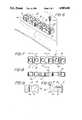
- FIG. 1is an perspective view of one of the embodiments of the bone plate of the present invention.
- FIG. 2is a top plan view of the bone plate shown in FIG. 1.
- FIG. 3is a side elevational view of the bone plate shown in FIG. 2.
- FIG. 4is a cross-sectional view taken along lines 4--4 of FIG. 2.
- FIG. 5is a cross-sectional view taken along lines 5--5 of FIG. 2.
- FIG. 6is a perspective view of another embodiment of the bone plate of the present invention.
- FIG. 7is a top plan view of the bone plate shown in FIG. 6.
- FIG. 8is a side elevation of view of the bone plate shown in FIG. 6.
- FIG. 9is a cross-sectional view taken along lines 9--9 of FIG. 7.
- FIG. 10is a cross-sectional view taken along the lines 10--10 of FIG. 7.
- FIG. 11is an enlarged fragmenting top view of the bone plate of FIG. 1.
- FIG. 12is a partial cross-sectional view taken along lines 12--12 of FIG. 11.
- FIG. 13is an enlarged cross-sectional end view of the plate similar to FIG. 4.
- the bone plate of the present inventionis made from the absorbable polylactide polymer disclosed in U.S. Pat. Nos. 4,539,981 and 4,550,449.
- the polymeris a polylactide polymer which has a very high molecular weight and is strong enough to be fabricated into bone plates, screws and other internal fixation devices.
- the polymerwill maintain its strength for a long enough period of time for the bone, onto which it is placed, to heal and it will be absorbed by the body over an extended period of time.
- the bone platewill lose its strength.
- the bonewill be healing and be capable of assuming its normal load. There is no benefit to the patient in maintaining the bone plate supporting the fracture site after the bone has healed.
- metal bone plateson the bone after the bone has healed is considered to be detrimental because of possible corrosion and because the rigid metal plates prevent the bone from responding to normal load carrying activity.
- Metal platesare generally surgically removed between one and one-half to two years after implantation.
- the bone plate of the present inventioncould also be fabricated from other absorbable polymers which have the necessary strength and which have the characteristics of maintaining a strength in the body for the required time period.
- the particular design of the bone plate of the present inventionis such that the bending stress at any point along the length of the bone plate does not exceed the level of stress through the center of a screw hole where the plate is fixed to the bone.
- the bending stressis determined by fixing the bone plate at one screw hole and bending the plate downward by loading weight at the next screw hole.
- the maximum stress at any point of the plateshould not exceed the yield strength of the polymer when the bending load applied by the tightening of the screw is 300 Newtons.
- the Yield strength of the polylactide polymeris 55 mpa.
- the stresses developed when the plate is loadedshould be relatively constant throughout the plate.
- relatively constantis meant that the stress, developed at the screw hole does not vary by more than 20%, preferably not more than 10%, from the highest stress at any other point in the plate when the plate is loaded by affixing the plate to a bone.
- the area around the screw holeis reinforced both at the top of the screw hole and along the sides of the bone plate.
- the reinforcementis minimized in both the top and side to insure that the total bone plate is not excessively wide or thick.
- Tis the unreinforced plate thickness measured at the side edge of the plate
- Wis one half the width of the unreinforced plate
- His the height of the top reinforcement measured from the unreinforced top surface of the plate
- Ris the radius of the side reinforcement of the plate measured from the centerline of a screw hole
- ris the radius of the top reinforcement measured along the centerline of a screw hole
- d' 2is the distance from the centerline of the screw hole to the point where the top reinforcement intersects the unreinforced top of the plate
- d 2is the distance from the transverse centerline of the screw hole to the point where the side reinforcement intersects the unreinforced side of the plate
- Lis the distance between adjacent screw holes measured from the screw hole centerlines
- R 1is the radius of the countersink measured from the screw hole centerline
- r 2is the radius of curvature of the bottom of the plate
- kis the minimum unreinforced thickness of the plate measured from the top of the radius of curvature of the bottom of the plate to the unreinforced top of the plate
- his the difference between T and k.
- the bone plate of the present inventionmay take different configurations.
- the plate shown in FIGS. 1-5is one typical configuration and the plate shown in FIGS. 6-10 is a second typical and preferred configuration. Both of these plates can be considered to have a generally rectangular main portion with a curved or arcuate lower surface to be placed on the surface of the bone to be repaired. There are reinforcing areas in the side and top of the plate around the screw holes. The difference between the plates of FIG. 1-5 and FIG. 6-10 is the shape of the top reinforcement area.
- the bone plate 20 shown in FIGS. 1-5is of a sufficient length to bridge the fracture site in the bone.
- the platehas a number of screw holes 21 on either side of a center section 22.
- the lower surface 23is arcuate to allow the plate to better fit the curvature of the bone to which the plate is attached.
- the unreinforced thickness of the plateis shown as T in the drawing FIG. 13 and the top reinforcement is shown as H.
- the unreinforced half width of the plateis shown as W and the radius of reinforced width as R in the drawings of FIG. 11.
- the centerline of the screw hole 29 or 30, in the direction through the thickness of the plateis referred to as the screw hole centerline.
- the centerline of the screw hole in the direction perpendicular to the length of the plateis referred to as the transverse centerline.
- the side reinforcing areacan be considered to be a right circular cylinder of a radius R, FIG. 11, which is concentric with the screw hole and which intersects the side of the rectangular main portion of the plate at a distance d 2 from the transverse centerline of the screw hole.
- the top reinforcing areacan be considered to be a portion of a sphere, which has a radius which intersects the top of the unreinforced rectangular portion of the plate at a distance d' 2 from the screw hole centerline of the screw hole.
- the dimension of d' 2is greater than the dimension of d 2 in order to obtain the desired properties of the plate.
- the top portion of the sphereis flattened at the countersink 24 to reduce the total height of the plate.
- top reinforcing element in the plate of FIGS. 6-10differs from the plate shown in FIGS. 1-5 only in the shape of the top reinforcing element.
- the top reinforcing element in the plate of FIGS. 6-10can be considered to be a portion of a right circular cylinder with its axis perpendicular to the length of the plate and extending through the side edges of the plate.
- the upper portion of the cylinderis removed for the countersink 24 and the top of the reinforcement area 28 has a flat surface 33 to reduce the thickness of the plate.
- a bone plateis affixed to a fractured bone on the tension side of the bone, i.e., on the convex side of the curve in the long dimension of the bone.
- the platewill be bent to conform to the curvature of the bone.
- the platewill be stressed as the screws are inserted into the bone. Assuming that the plate is first attached to the bone with a screw through screw hole 29, the maximum stress will be developed at the screw hole 29 when a screw placed through screw hole 30 is affixed to the bone.
- the side reinforcement 26 and the top reinforcement 27prevents the plate from breaking at the screw hole 29.
- the stressesare determined or calculated along various lines across the width of the plate where the plate is most likely to break when the plate is loaded as it is affixed to a bone.
- the line S 1is located through the screw hole.
- the line S 2 apasses through the intersection of the side reinforcement and the unreinforced side of the plate around screw hole 30.
- the line S 2 'apasses through the intersection of the top reinforcement area and the unreinforced top of the plate around the screw hole 30.
- the line S 2 'bpasses through the point where the top reinforcement around the next adjacent screw hole 29 intersects the unreinforced top of the plate.
- the line S 2 bpasses through the point where the side reinforcement of the next adjacent screw hole 29 intersects the unreinforced side of the plate.
- the plateis first fixed at screw hole 29 and the load is applied at screw hole 30.
- bone plateshave a length of between about 50 and 200 millimeters.
- the minimum lengthis dictated by the desirability to have at least four screw holes in the plate.
- the width of the bone plateis dependent on the size of the bone to which the plate will be attached.
- the unreinforced width of the platesare between 5 and 15 millimeters.
- the unreinforced height of the plates of the present inventionare between 4 and 10 millimeters. The unreinforced height is measured from the bottom of the plate to the unreinforced surface at the top of the plate.
- the reinforcement in the width of the plateshould be between 1 and 4 millimeters.
- the reinforcement in the height of the plateshould be between 1 to 5 millimeters depending on the unreinforced thickness of the plate.
- the following Examplesare show designs of various bone plates which are reinforced in different areas and show the effect of the reinforcement on the stresses that would be developed in the bone plate.
- the ultimate tensile strength of the polylactide polymeris about 70 MPA.
- the stress at the screw holeexceeds the yield strength of the polymer and the plate would fail at the screw hole if implanted.
- Example IIThe stresses are calculated for a plate as in Example I.
- the platehas a uniform thickness of 6.4 millimeters.
- the resultsare shown in the following Table:
- the stresses generated at the screw hole due to 300 N and at 535 N loadare greater than the yield and the ultimate strength of the polymer.
- the stress generated due to 535 N loading around the screw holeis greater than the ultimate strength of the polymer.
- Example IA plate was fabricated as in Example I in the form shown in FIGS. 1-5 of the drawings.
- the unreinforced thicknesswas 5.0 millimeters
- the top reinforcementwas 4.8 millimeters in maximum thickness
- the side reinforcementwas 3.0 millimeters in width.
- the stresswas determined at a load 300 N and of 535 N as in Example I and the results as shown in the following Table:
- a bone platewas fabricated of the design shown in FIG. 6-10.
- the platehad a unreinforced thickness of 5 millimeters and a top reinforcement of 2.6 millimeters.
- the platewas 12 millimeters wide and had a side reinforcement of 3.2 millimeters, 1.6 millimeters on each side.
- the platewas 73.20 millimeters in length and had six screw holes spaced 12 millimeters from center line to center line with a space of 15 millimeters between the center holes.
- the platewas loaded with a force of 300 Newtons. in a three point bending configuration with the force applied at a screw hole.
- the stresses developedwere:
Landscapes
- Health & Medical Sciences (AREA)
- Orthopedic Medicine & Surgery (AREA)
- Life Sciences & Earth Sciences (AREA)
- Surgery (AREA)
- Heart & Thoracic Surgery (AREA)
- Animal Behavior & Ethology (AREA)
- General Health & Medical Sciences (AREA)
- Public Health (AREA)
- Veterinary Medicine (AREA)
- Epidemiology (AREA)
- Vascular Medicine (AREA)
- Neurology (AREA)
- Nuclear Medicine, Radiotherapy & Molecular Imaging (AREA)
- Engineering & Computer Science (AREA)
- Biomedical Technology (AREA)
- Medical Informatics (AREA)
- Molecular Biology (AREA)
- Chemical & Material Sciences (AREA)
- Chemical Kinetics & Catalysis (AREA)
- Surgical Instruments (AREA)
Abstract
Description
This application is a continuation-in-part of application Ser. No. 923,234 filed Oct. 27, 1986.
The present invention relates to a bone plate used as an aid for osteosynthesis and which is made of a material which will be absorbed in the body.
Metallic bone plates and screws have been used for sometime in osteosynthesis to approximate fractured or broken bones in the body. These plates are generally made of materials such as stainless steel, chrome cobalt, titanium and various alloys of such metals. The bone plates are used to hold fractured bones in position so that they may heal in a proper manner. The bone plates offer advantages over the immobilization of the bone using only simple casting techniques. The use of internal fixation eliminates long periods of casting and allows early active joint movement which provides greater or earlier mobility to the patient.
It has been suggested that it would be desirable to form such bone plates from materials which would be absorbed by the body to eliminate the necessity of a second surgical procedure to remove the bone plates after the bone has healed. An absorbable polymer capable of being fabricated into a bone fixation device or bone plate is disclosed in U.S. Pat. Nos. 4,539,981 and 4,550,449.
Bone plates fabricated from metal have been made in various designs. Generally, the design consists of a bar of the particular metal which is curved on the surface which will be placed against the bone. The plate has a number of screw holes in the plate and screws are introduced through the holes to secure the plate to the bone U.S. Pat. No. 3,463,148 discloses a metallic bone plate which has a substantially constant cross-sectional area. The plate has screw holes through the plate which are spaced on either side of a longitudinal center line. The metal in the area of the screw holes is thicker than the area of the metal between the screw holes.
U.S Pat. No. 4,219,015 discloses a metallic bone plate in which the bending resistance moment, W=I/e, is relatively constant throughout the plate and the stress is variable. Specifically, the lower limiting value of the bending resistance moment is, at most, 30% smaller than the upper limiting value. In the plate of the present invention the stress is relatively constant and the bending resistance moment is variable.
U.S. Pat. No. 4,429,690 discloses a metal plate for the fixation of broken bones comprising two longitudinal bars joined by an array of humped bridges or crossed brackets evenly spaced along the length of the bars and having holes to set cortical screws. The design of this plate is indicated to resists fracture to a greater degree than the plates previously used.
All of the above mentioned bone plates are designed to be fabricated from a relatively strong metal, such as stainless steel, chrome cobalt or titanium. The absorbable polymer from which the present bone plates are made does not have the strength of these metals. The strength of the absorbable polymer is significantly less than the strength of the metal from which the metallic bone plates are fabricated and, for that reason, the design of the metallic bone plates are not necessarily usable in a bone plate fabricated from an absorbable polymer. Although it would be theoretically possible to simply increase the thickness of an absorbable bone plate to compensate for the difference in strength when compared to a metallic bone plate, such simple modifications are not desirable. It is necessary to minimize the thickness of any bone plate so that the plate will not sit too high on the bone and cause difficulty in the coverage of the bone plate with soft tissue following a surgical procedure. If the plate is too thick, it simply cannot be used. Similarly, anatomical restrictions also limit the width of a bone plate. The bone plate cannot be too much wider than the width of the bone for which it is designed to repair.
The present invention provides a bone plate made from absorbable polymer which can be used in the fixation of bones without fear of the bone plate breaking.
The present bone plate is constructed so that the stresses developed when the bone plate is used are relatively constant and are below the yield strength of the absorbable polymer from which the plate is fabricated. To maintain the stresses relatively constant, the area of the plate around the screw holes is reinforced in both the width and height of the plate. The reinforcement areas are optimized to insure that when the plate is subjected to the stresses generated upon fixation of the bone, the plate will not break and that the dimensions of the plate will be a minimum thickness and width.
FIG. 1 is an perspective view of one of the embodiments of the bone plate of the present invention.
FIG. 2 is a top plan view of the bone plate shown in FIG. 1.
FIG. 3 is a side elevational view of the bone plate shown in FIG. 2.
FIG. 4 is a cross-sectional view taken along lines 4--4 of FIG. 2.
FIG. 5 is a cross-sectional view taken alonglines 5--5 of FIG. 2.
FIG. 6 is a perspective view of another embodiment of the bone plate of the present invention.
FIG. 7 is a top plan view of the bone plate shown in FIG. 6.
FIG. 8 is a side elevation of view of the bone plate shown in FIG. 6.
FIG. 9 is a cross-sectional view taken alonglines 9--9 of FIG. 7.
FIG. 10 is a cross-sectional view taken along the lines 10--10 of FIG. 7.
FIG. 11 is an enlarged fragmenting top view of the bone plate of FIG. 1.
FIG. 12 is a partial cross-sectional view taken alonglines 12--12 of FIG. 11.
FIG. 13 is an enlarged cross-sectional end view of the plate similar to FIG. 4.
The bone plate of the present invention is made from the absorbable polylactide polymer disclosed in U.S. Pat. Nos. 4,539,981 and 4,550,449. The polymer is a polylactide polymer which has a very high molecular weight and is strong enough to be fabricated into bone plates, screws and other internal fixation devices. The polymer will maintain its strength for a long enough period of time for the bone, onto which it is placed, to heal and it will be absorbed by the body over an extended period of time. As the polymer is absorbed, the bone plate will lose its strength. At the same time, the bone will be healing and be capable of assuming its normal load. There is no benefit to the patient in maintaining the bone plate supporting the fracture site after the bone has healed. The presence of metal bone plates on the bone after the bone has healed is considered to be detrimental because of possible corrosion and because the rigid metal plates prevent the bone from responding to normal load carrying activity. Metal plates are generally surgically removed between one and one-half to two years after implantation. The bone plate of the present invention could also be fabricated from other absorbable polymers which have the necessary strength and which have the characteristics of maintaining a strength in the body for the required time period.
The particular design of the bone plate of the present invention is such that the bending stress at any point along the length of the bone plate does not exceed the level of stress through the center of a screw hole where the plate is fixed to the bone. The bending stress is determined by fixing the bone plate at one screw hole and bending the plate downward by loading weight at the next screw hole. In the plate of the present invention, the maximum stress at any point of the plate should not exceed the yield strength of the polymer when the bending load applied by the tightening of the screw is 300 Newtons. The Yield strength of the polylactide polymer is 55 mpa.
In addition, the stresses developed when the plate is loaded should be relatively constant throughout the plate. By relatively constant is meant that the stress, developed at the screw hole does not vary by more than 20%, preferably not more than 10%, from the highest stress at any other point in the plate when the plate is loaded by affixing the plate to a bone.
The area around the screw hole is reinforced both at the top of the screw hole and along the sides of the bone plate. The reinforcement is minimized in both the top and side to insure that the total bone plate is not excessively wide or thick.
In order to provide a plate of constant strength, it is necessary to maintain a relationship between certain dimensions of the plate and in particular the reinforced areas of the plate. The dimensions are shown in FIG. 11-13 using the following designations:
T is the unreinforced plate thickness measured at the side edge of the plate
W is one half the width of the unreinforced plate
H is the height of the top reinforcement measured from the unreinforced top surface of the plate
R is the radius of the side reinforcement of the plate measured from the centerline of a screw hole
r is the radius of the top reinforcement measured along the centerline of a screw hole
d'2 is the distance from the centerline of the screw hole to the point where the top reinforcement intersects the unreinforced top of the plate
d2 is the distance from the transverse centerline of the screw hole to the point where the side reinforcement intersects the unreinforced side of the plate
L is the distance between adjacent screw holes measured from the screw hole centerlines
R1 is the radius of the countersink measured from the screw hole centerline
r2 is the radius of curvature of the bottom of the plate
k is the minimum unreinforced thickness of the plate measured from the top of the radius of curvature of the bottom of the plate to the unreinforced top of the plate
h is the difference between T and k.
In order to provide a plate with acceptable strength and optimum thickness, the following relationships must be met. ##EQU1## The bone plate of the present invention may take different configurations. The plate shown in FIGS. 1-5 is one typical configuration and the plate shown in FIGS. 6-10 is a second typical and preferred configuration. Both of these plates can be considered to have a generally rectangular main portion with a curved or arcuate lower surface to be placed on the surface of the bone to be repaired. There are reinforcing areas in the side and top of the plate around the screw holes. The difference between the plates of FIG. 1-5 and FIG. 6-10 is the shape of the top reinforcement area. Thebone plate 20 shown in FIGS. 1-5 is of a sufficient length to bridge the fracture site in the bone. The plate has a number of screw holes 21 on either side of acenter section 22. Thelower surface 23 is arcuate to allow the plate to better fit the curvature of the bone to which the plate is attached. The unreinforced thickness of the plate is shown as T in the drawing FIG. 13 and the top reinforcement is shown as H. The unreinforced half width of the plate is shown as W and the radius of reinforced width as R in the drawings of FIG. 11. There is acountersink 24 at the top of the screw holes 21 so thescrew 25 may be almost flush with the upper surface of the plate when the plate is attached to the bone. For purposes of orientation, the centerline of thescrew hole
The side reinforcing area can be considered to be a right circular cylinder of a radius R, FIG. 11, which is concentric with the screw hole and which intersects the side of the rectangular main portion of the plate at a distance d2 from the transverse centerline of the screw hole. The top reinforcing area can be considered to be a portion of a sphere, which has a radius which intersects the top of the unreinforced rectangular portion of the plate at a distance d'2 from the screw hole centerline of the screw hole. The dimension of d'2 is greater than the dimension of d2 in order to obtain the desired properties of the plate. The top portion of the sphere is flattened at thecountersink 24 to reduce the total height of the plate. The plate shown in FIGS. 6-10 differs from the plate shown in FIGS. 1-5 only in the shape of the top reinforcing element. The top reinforcing element in the plate of FIGS. 6-10 can be considered to be a portion of a right circular cylinder with its axis perpendicular to the length of the plate and extending through the side edges of the plate. The upper portion of the cylinder is removed for thecountersink 24 and the top of thereinforcement area 28 has aflat surface 33 to reduce the thickness of the plate.
The stresses that are developed when a bone plate is in use can be best explained with reference to FIGS. 11-13. A bone plate is affixed to a fractured bone on the tension side of the bone, i.e., on the convex side of the curve in the long dimension of the bone. In order to firmly affix the plate to the bone, the plate will be bent to conform to the curvature of the bone. The plate will be stressed as the screws are inserted into the bone. Assuming that the plate is first attached to the bone with a screw throughscrew hole 29, the maximum stress will be developed at thescrew hole 29 when a screw placed throughscrew hole 30 is affixed to the bone. Theside reinforcement 26 and thetop reinforcement 27 prevents the plate from breaking at thescrew hole 29. In the Examples that follow, the stresses are determined or calculated along various lines across the width of the plate where the plate is most likely to break when the plate is loaded as it is affixed to a bone. The line S1 is located through the screw hole. The line S2 a passes through the intersection of the side reinforcement and the unreinforced side of the plate aroundscrew hole 30. The line S2 'a passes through the intersection of the top reinforcement area and the unreinforced top of the plate around thescrew hole 30. The line S2 'b passes through the point where the top reinforcement around the nextadjacent screw hole 29 intersects the unreinforced top of the plate. The line S2 b passes through the point where the side reinforcement of the nextadjacent screw hole 29 intersects the unreinforced side of the plate. In the Examples the plate is first fixed atscrew hole 29 and the load is applied atscrew hole 30.
Generally, bone plates have a length of between about 50 and 200 millimeters. The minimum length is dictated by the desirability to have at least four screw holes in the plate. There is no limitation on the maximum length of the plates other than the maximum length of a bone to be repaired. For most repairs, the bone plates will be between 50 and 200 millimeters in length. The width of the bone plate is dependent on the size of the bone to which the plate will be attached. Generally, the unreinforced width of the plates are between 5 and 15 millimeters. The unreinforced height of the plates of the present invention are between 4 and 10 millimeters. The unreinforced height is measured from the bottom of the plate to the unreinforced surface at the top of the plate. In order to obtain the desirable strength properties in the plates of the present invention, the reinforcement in the width of the plate should be between 1 and 4 millimeters. The reinforcement in the height of the plate should be between 1 to 5 millimeters depending on the unreinforced thickness of the plate.
The following Examples are show designs of various bone plates which are reinforced in different areas and show the effect of the reinforcement on the stresses that would be developed in the bone plate. The ultimate tensile strength of the polylactide polymer is about 70 MPA.
The stress in a polylactide plate, 4.0 millimeters thick is calculated. The stress in the plate at a screw hole and the highest stress at any other point in the plate are calculated at different loads. The results are shown in the following Table:
______________________________________ Stress LOAD 300 N 535 N ______________________________________ Screw Hole 150.3 M Pa 267 M Pa Highest Stress 59.7 M Pa 106 M Pa at any other point ______________________________________
The stress at the screw hole exceeds the yield strength of the polymer and the plate would fail at the screw hole if implanted.
The stresses are calculated for a plate as in Example I. The plate has a uniform thickness of 6.4 millimeters. The results are shown in the following Table:
______________________________________ Stress LOAD 300 N 535 N ______________________________________ Screw Hole 66.4 M Pa 118.2 M Pa Highest Stress 29.3 M Pa 52.1 M Pa at any other point ______________________________________
The stresses generated at the screw hole due to 300 N and at 535 N load are greater than the yield and the ultimate strength of the polymer.
The stresses are calculated for a bone plate having a thickness of 4 millimeters and additional thickness of 2.4 millimeters around the top of the screw holes. The results are shown in the following Table:
______________________________________ Stress LOAD 300 N 535 N ______________________________________ Screw Hole 66.4 M Pa 118.2 M Pa Highest Stress 43.8 M Pa 78.0 M Pa at any other point ______________________________________
The stress generated due to 535 N loading around the screw hole is greater than the ultimate strength of the polymer.
The stresses are calculated for a plate having a thickness of 4 millimeters and an additional thickness of 2.8 millimeters around the sides of the screw holes. The results are shown in the following Table:
______________________________________ Stress LOAD 300 N 535 N ______________________________________ Screw Hole 100.3 M Pa 178.6 M Pa ______________________________________
The stresses exceeded the ultimate strength of the polymer.
The stresses are calculated for a plate having a thickness of 4.0 millimeters and a reinforcement around the top of the screw hole of 2.4 millimeters and a reinforcement around the side of the screw hole of 2.8 millimeters. The results are shown in the following Table:
______________________________________ Stress LOAD 300 N 535 N ______________________________________ Screw Hole 43.4 M Pa 77.4 M Pa Highest Stress 43.8 M Pa 78.0 M Pa at any other point ______________________________________
The stresses in this plate are well balanced and within the yield strength of the polymer. A plate of this design would be suitable for use in fixation of bones.
The stresses were calculated for a plate having a thickness of 3.0 millimeters, a top reinforcement of 2.4 millimeters and a side reinforcement of 2.8 millimeters. The results are shown in the following Table:
______________________________________ Stress LOAD 300 N 535 N ______________________________________ Screw Hole 58.1 M Pa 103.6 M Pa Highest Stress 70.5 M Pa 125.6 M Pa at any other point ______________________________________
In this plate, the stress in the unreinforced area of the plate exceeded the yield strength of the polymer.
The stresses were calculated for a plate having a thickness of 4 millimeters, a top reinforcement of 3.4 millimeters and a side reinforcement of 4.8 millimeters. The results are shown in the following Table:
______________________________________ Stress LOAD 300 N 535 N ______________________________________ Screw Hole 27.1 M Pa 48.3 M Pa Highest Stress 48.0 M Pa 85.4 M Pa at any other point ______________________________________
Although this plate is acceptable in terms of strength, it is anatomically less desirable since it is thicker and wider than the plate of Example V.
A plate was fabricated as in Example I in the form shown in FIGS. 1-5 of the drawings. The unreinforced thickness was 5.0 millimeters, the top reinforcement was 4.8 millimeters in maximum thickness and the side reinforcement was 3.0 millimeters in width. The stress was determined at a load 300 N and of 535 N as in Example I and the results as shown in the following Table:
______________________________________ Stress LOAD 300 N 535 N ______________________________________ Screw Hole 32.4 M Pa 57.8 M Pa Highest Stress 37.3 M Pa 66.5 M Pa at any other point ______________________________________
A bone plate was fabricated of the design shown in FIG. 6-10. The plate had a unreinforced thickness of 5 millimeters and a top reinforcement of 2.6 millimeters. The plate was 12 millimeters wide and had a side reinforcement of 3.2 millimeters, 1.6 millimeters on each side. The plate was 73.20 millimeters in length and had six screw holes spaced 12 millimeters from center line to center line with a space of 15 millimeters between the center holes. The plate was loaded with a force of 300 Newtons. in a three point bending configuration with the force applied at a screw hole. The stresses developed were:
______________________________________ Location Stress M Pa ______________________________________ S.sub.2 a 14.26 S.sub.2 'a 31.81 S.sub.2 'b 29.67 S.sub.2 b 22.39 S.sub.1 31.1 ______________________________________
The force was increased to 535 Newtons and the stresses determined
______________________________________ Location Stress M pa ______________________________________ S.sub.2 a 25.41 S.sub.2 'a 56.79 S.sub.2 'b 52.97 S.sub.2 b 39.96 S.sub.1 55.52 ______________________________________
Claims (8)
1. An absorbable bone plate comprising an elongated bar-like body having a lower surface, an upper surface, opposite sides and opposite ends, a plurality of screw holes extending through said plate from the upper surface through the lower surface, the width of the plate being extended around the screw holes as a reinforcement and in which the thickness of the plate is extended on the upper surface of the plate in an arcuate shape around the screw holes as a reinforcement area so that the stresses developed around the screw holes on implantation are not significantly greater than the highest stresses developed in any unreinforced area of the plate, and in which the dimensions of the plate meet the limitations: ##EQU2## where: W is one half the width of the unreinforced plate
R is the radius of the side reinforcement of the plate measured from the centerline of a screw hole
H is the height of the top reinforcement measured from the unreinforced top surface of the plate
r is the radius of the top reinforcement of the plate measured from a point on the centerline of a screw hole
d'2 is the distance from the centerline of the screw hole to the point where the top reinforcement intersects the unreinforced top of the plate
d2 is the distance from the transverse centerline of the screw hole to the point where the side reinforcement intersects the unreinforced side of the plate
L is the distance between adjacent screw holes measured from the screw hole centerlines
R1 is the radius of the countersink measured from the screw hole centerline
r2 is the radius of curvature of the bottom of the plate
k is the minimum unreinforced thickness of the plate measured from the top of the radius of curvature of the bottom of the plate to the unreinforced top of the plate
T is the unreinforced plate thickness at the side edge of the plate
h is the difference between T and k.
2. The bone plate of claim 1 in which the top of the reinforced area of the plate around the screw holes is flattened and countersunk around the screw holes.
3. The bone plate of claim 1 in which the top reinforced area is a section of a sphere.
4. The bone plate of claim 1 in which the top reinforced area is a section of the right cylinder having an axis along the transverse centerline of the screw hole.
5. The bone plate of claim 1 in which the stresses in the plate across a screw hole where the plate is attached to bone is not different by more than 20% from the highest stresses developed anywhere else in the plate up to the next screw hole when the plate is subjected to force.
6. The bone plate of claim 1 in which the stresses in the plate across a screw hole where the plate is attached to bone is not different by more than 10% from the highest stresses developed anywhere else in the plate up to the next screw hole when the plate is subjected to force.
7. The bone plate of claim 4 in which the stresses in the plate across a screw hole where the plate is attached to bone is not different by more than 20% from the highest stresses developed anywhere else in the plate up to the next screw hole when the plate is subjected to force.
8. The bone plate of claim 4 in which the stresses in the plate across a screw hole where the plate is attached to bone is not different by more than 10% from the highest stresses developed anywhere else in the plate up to the next screw hole when the plate is subjected to force.
Priority Applications (1)
| Application Number | Priority Date | Filing Date | Title |
|---|---|---|---|
| US07/224,047US4905680A (en) | 1986-10-27 | 1988-07-25 | Absorbable bone plate |
Applications Claiming Priority (2)
| Application Number | Priority Date | Filing Date | Title |
|---|---|---|---|
| US92323486A | 1986-10-27 | 1986-10-27 | |
| US07/224,047US4905680A (en) | 1986-10-27 | 1988-07-25 | Absorbable bone plate |
Related Parent Applications (1)
| Application Number | Title | Priority Date | Filing Date |
|---|---|---|---|
| US92323486AContinuation-In-Part | 1986-10-27 | 1986-10-27 |
Publications (1)
| Publication Number | Publication Date |
|---|---|
| US4905680Atrue US4905680A (en) | 1990-03-06 |
Family
ID=26918379
Family Applications (1)
| Application Number | Title | Priority Date | Filing Date |
|---|---|---|---|
| US07/224,047Expired - LifetimeUS4905680A (en) | 1986-10-27 | 1988-07-25 | Absorbable bone plate |
Country Status (1)
| Country | Link |
|---|---|
| US (1) | US4905680A (en) |
Cited By (127)
| Publication number | Priority date | Publication date | Assignee | Title |
|---|---|---|---|---|
| US5108399A (en)* | 1988-09-17 | 1992-04-28 | Boehringer Ingelheim Gmbh | Device for osteosynthesis and process for producing it |
| US5275601A (en)* | 1991-09-03 | 1994-01-04 | Synthes (U.S.A) | Self-locking resorbable screws and plates for internal fixation of bone fractures and tendon-to-bone attachment |
| US5275602A (en)* | 1989-12-04 | 1994-01-04 | Gunze Limited | Bone-joining articles |
| US5290281A (en)* | 1992-06-15 | 1994-03-01 | Medicon Eg | Surgical system |
| US5324519A (en)* | 1989-07-24 | 1994-06-28 | Atrix Laboratories, Inc. | Biodegradable polymer composition |
| US5342395A (en)* | 1990-07-06 | 1994-08-30 | American Cyanamid Co. | Absorbable surgical repair devices |
| US5368859A (en)* | 1989-07-24 | 1994-11-29 | Atrix Laboratories, Inc. | Biodegradable system for regenerating the periodontium |
| US5372598A (en)* | 1987-05-14 | 1994-12-13 | Howmedica Gmbh | Small bone plate for cranial or facial fractures or the like |
| US5387243A (en)* | 1992-11-23 | 1995-02-07 | Zimmer, Inc. | Method for converting a cementable implant to a press fit implant |
| DE4425441A1 (en)* | 1993-09-09 | 1995-03-16 | Synthes Ag | Osteosynthetic pressure plate |
| US5413577A (en)* | 1987-04-07 | 1995-05-09 | Pollock; Richard A. | Anatomical precontoured plating |
| WO1995031147A1 (en)* | 1994-05-12 | 1995-11-23 | Advanced Spine Fixation Systems, Inc. | Cervical spine rod fixation system |
| US5475063A (en)* | 1991-02-12 | 1995-12-12 | United States Surgical Corporation | Blends of glycolide and/or lactide polymers and caprolactone and/or trimethylene carbonate polymers and absorbable surgical devices made |
| US5487897A (en)* | 1989-07-24 | 1996-01-30 | Atrix Laboratories, Inc. | Biodegradable implant precursor |
| US5501684A (en)* | 1992-06-25 | 1996-03-26 | Synthes (U.S.A.) | Osteosynthetic fixation device |
| US5527341A (en)* | 1991-05-24 | 1996-06-18 | Synthes (U.S.A) | Resorbable tendon and bone augmentation device |
| US5634926A (en)* | 1995-04-25 | 1997-06-03 | Jobe; Richard P. | Surgical bone fixation apparatus |
| US5674222A (en)* | 1994-06-01 | 1997-10-07 | Synthes (U.S.A.) | Forked plate |
| US5674286A (en)* | 1991-02-12 | 1997-10-07 | United States Surgical Corporation | Bioabsorbable medical implants |
| US5681873A (en)* | 1993-10-14 | 1997-10-28 | Atrix Laboratories, Inc. | Biodegradable polymeric composition |
| US5690631A (en)* | 1996-09-11 | 1997-11-25 | Walter Lorenz Surgical, Inc. | Multi-configurable plating system |
| US5766176A (en)* | 1996-09-11 | 1998-06-16 | Walter Lorenz Surgical, Inc. | Formable mesh |
| US5779706A (en)* | 1992-06-15 | 1998-07-14 | Medicon Eg | Surgical system |
| US5785712A (en)* | 1996-04-16 | 1998-07-28 | Terray Corporation | Reconstruction bone plate |
| USD402032S (en) | 1996-02-20 | 1998-12-01 | Walter Lorenz Surgical, Inc. | Neuro gap plate for osteosynthesis |
| US5868746A (en)* | 1994-03-01 | 1999-02-09 | Biomet, Inc. | Method and apparatus for securing adjacent bone portions |
| US5868749A (en)* | 1996-04-05 | 1999-02-09 | Reed; Thomas M. | Fixation devices |
| USD406646S (en)* | 1996-02-20 | 1999-03-09 | Walter Lorenz Surgical, Inc. | Neuro sub-temporal plate for osteosynthesis |
| US5916200A (en)* | 1997-10-01 | 1999-06-29 | Walter Lorenz Surgical, Inc. | Apparatus and method for stabilization of a cranial shunt |
| KR19990069699A (en)* | 1998-02-12 | 1999-09-06 | 엠. 제이크스-바우만 | Bone Plate |
| US5993475A (en)* | 1998-04-22 | 1999-11-30 | Bristol-Myers Squibb Co. | Tissue repair device |
| US6017345A (en)* | 1997-05-09 | 2000-01-25 | Spinal Innovations, L.L.C. | Spinal fixation plate |
| US6093201A (en)* | 1999-01-19 | 2000-07-25 | Ethicon, Inc. | Biocompatible absorbable polymer plating system for tissue fixation |
| US6187008B1 (en) | 1999-07-07 | 2001-02-13 | Bristol-Myers Squibb | Device for temporarily fixing bones |
| DE19936133A1 (en)* | 1999-07-31 | 2001-02-15 | Aesculap Ag & Co Kg | Plastic cruciform bone-plate has central arm and two arms at each end, recesses for centering, with sloping rims and flat base |
| US6206883B1 (en) | 1999-03-05 | 2001-03-27 | Stryker Technologies Corporation | Bioabsorbable materials and medical devices made therefrom |
| US6228954B1 (en) | 1991-02-12 | 2001-05-08 | United States Surgical Corporation | Blends of glycolide and/or lactide polymers and caprolactone and/or trimethylene carbonate polymers and absorabable surgical devices made therefrom |
| US6258091B1 (en) | 1996-02-14 | 2001-07-10 | Walter Lorenz Surgical Inc. | Bone fastener and instrument for insertion thereof |
| US6270500B1 (en) | 1996-02-03 | 2001-08-07 | Karl-Dieter Lerch | Device for postoperative fixation back into the cranium of a plug of bone removed therefrom during a surgical operation |
| WO2001062136A3 (en)* | 2000-02-24 | 2002-02-21 | Stryker Instr | Bioabsorbable plates, fasteners, tools and method of using same |
| US6379363B1 (en) | 1999-09-24 | 2002-04-30 | Walter Lorenz Surgical, Inc. | Method and apparatus for reattachment of a cranial flap using a cranial clamp |
| US6466822B1 (en) | 2000-04-05 | 2002-10-15 | Neuropace, Inc. | Multimodal neurostimulator and process of using it |
| US6473639B1 (en) | 2000-03-02 | 2002-10-29 | Neuropace, Inc. | Neurological event detection procedure using processed display channel based algorithms and devices incorporating these procedures |
| US20030004515A1 (en)* | 1999-12-06 | 2003-01-02 | Raymond Curtis | Resorbable bone plate |
| US6529774B1 (en) | 2000-11-09 | 2003-03-04 | Neuropace, Inc. | Extradural leads, neurostimulator assemblies, and processes of using them for somatosensory and brain stimulation |
| US20030149433A1 (en)* | 2000-06-09 | 2003-08-07 | Markus Hehli | Plastic implant for osteosynthesis |
| US6607548B2 (en) | 2001-05-17 | 2003-08-19 | Inion Ltd. | Resorbable polymer compositions |
| US6685707B2 (en) | 2001-09-25 | 2004-02-03 | Walter Lorenz Surgical, Inc. | Cranial clamp and method for fixating a bone plate |
| US20040068262A1 (en)* | 2002-10-02 | 2004-04-08 | Mark Lemos | Soft tissue fixation implant |
| US6747121B2 (en) | 2001-09-05 | 2004-06-08 | Synthes (Usa) | Poly(L-lactide-co-glycolide) copolymers, methods for making and using same, and devices containing same |
| US20040127846A1 (en)* | 1999-09-24 | 2004-07-01 | Dunn Richard L. | Coupling syringe system and methods for obtaining a mixed composition |
| US20040167521A1 (en)* | 2001-04-24 | 2004-08-26 | Paul De Windt | Fixing device for fixing vertebra parts |
| US20040254579A1 (en)* | 2003-03-20 | 2004-12-16 | Stryker Trauma S.A. | Bone connection device |
| US20050010226A1 (en)* | 2003-05-30 | 2005-01-13 | Grady Mark P. | Bone plate |
| US6869432B2 (en) | 2000-04-19 | 2005-03-22 | Synthes (U.S.A.) | Device for the articulated connection of two bodies |
| US20050080421A1 (en)* | 1999-09-13 | 2005-04-14 | Synthes (Usa) | Bone plating system |
| US20050085812A1 (en)* | 2003-10-21 | 2005-04-21 | Sherman Michael C. | Apparatus and method for providing dynamizable translations to orthopedic implants |
| US20050085814A1 (en)* | 2003-10-21 | 2005-04-21 | Sherman Michael C. | Dynamizable orthopedic implants and their use in treating bone defects |
| US20050136764A1 (en)* | 2003-12-18 | 2005-06-23 | Sherman Michael C. | Designed composite degradation for spinal implants |
| US20050177162A1 (en)* | 2002-07-23 | 2005-08-11 | Fondel Finance B.V. | Supporting element for attachment to bone |
| US6944501B1 (en) | 2000-04-05 | 2005-09-13 | Neurospace, Inc. | Neurostimulator involving stimulation strategies and process for using it |
| US20050228386A1 (en)* | 2004-04-08 | 2005-10-13 | Tara Ziolo | Bone fixation device |
| US20060004361A1 (en)* | 2004-06-21 | 2006-01-05 | Garry Hayeck | Bone plate |
| US20060149250A1 (en)* | 2004-12-14 | 2006-07-06 | Castaneda Javier E | Bone plate with pre-assembled drill guide tips |
| US20060149251A1 (en)* | 2004-12-22 | 2006-07-06 | Tara Ziolo | Bone fixation system |
| US7128927B1 (en) | 1998-04-14 | 2006-10-31 | Qlt Usa, Inc. | Emulsions for in-situ delivery systems |
| US20070083207A1 (en)* | 2005-09-21 | 2007-04-12 | Tara Ziolo | Variable angle bone fixation assembly |
| US20070118130A1 (en)* | 2005-11-22 | 2007-05-24 | Depuy Spine, Inc. | Implant fixation methods and apparatus |
| US20070118127A1 (en)* | 2005-11-22 | 2007-05-24 | Depuy Spine, Inc. | Implant fixation methods and apparatus |
| US20070118121A1 (en)* | 2005-10-07 | 2007-05-24 | Alphatec Spine, Inc. | Adjustable occipital plate |
| US20070118129A1 (en)* | 2005-11-22 | 2007-05-24 | Depuy Spine, Inc. | Implant fixation methods and apparatus |
| US20070118128A1 (en)* | 2005-11-22 | 2007-05-24 | Depuy Spine, Inc. | Implant fixation methods and apparatus |
| US20070162026A1 (en)* | 2001-10-18 | 2007-07-12 | Fxdevices Llc | System and method for a cap used in the fixation of bone fractures |
| US20070233111A1 (en)* | 2006-03-20 | 2007-10-04 | Orbay Jorge L | Bone Plate Shaping System |
| US20070233112A1 (en)* | 2006-03-20 | 2007-10-04 | Orbay Jorge L | Method of Bone Plate Shaping |
| US20070260248A1 (en)* | 2001-10-18 | 2007-11-08 | Fxdevices, Llc | Cannulated bone screw system and method |
| US20080021452A1 (en)* | 2006-07-18 | 2008-01-24 | Dustin Ducharme | Calcaneal plate |
| US20080147127A1 (en)* | 2001-10-18 | 2008-06-19 | Fxdevices, Llc | Bone screw system and method |
| US20080147126A1 (en)* | 2001-10-18 | 2008-06-19 | Fxdevices, Llc | System and method for a cap used in the fixation of bone fractures |
| US20080243132A1 (en)* | 2001-10-18 | 2008-10-02 | Fx Devices, Llc | Tensioning system and method for the fixation of bone fractures |
| US20080243191A1 (en)* | 2001-10-18 | 2008-10-02 | Fx Devices, Llc | Adjustable bone plate fixation system and metho |
| US20090048606A1 (en)* | 2001-10-18 | 2009-02-19 | Fxdevices Llc | Guide system and method for the fixation of bone fractures |
| US20090076553A1 (en)* | 1999-09-14 | 2009-03-19 | Dietmar Wolter | Fixation system for bones |
| US20090082816A1 (en)* | 2007-09-20 | 2009-03-26 | Graham Matthew R | Remodelable orthopaedic spacer and method of using the same |
| US20090118769A1 (en)* | 2007-11-02 | 2009-05-07 | Sixto Jr Robert | Fracture Fixation Plate for the Proximal Radius |
| US20090131936A1 (en)* | 2001-10-18 | 2009-05-21 | Kishore Tipirneni | System and method for the fixation of bone fractures |
| US20090131990A1 (en)* | 2001-10-18 | 2009-05-21 | Kishore Tipirneni | Bone screw system and method |
| US20090131991A1 (en)* | 2001-10-18 | 2009-05-21 | Kishore Tipirneni | System and method for the fixation of bone fractures |
| US20090177199A1 (en)* | 2001-10-18 | 2009-07-09 | Lagwire, Llc | Cap device for use in the fixation of bone structures |
| US20090254129A1 (en)* | 2007-04-30 | 2009-10-08 | Kishore Tipirneni | Bone screw system and method for the fixation of bone fractures |
| US20090306718A1 (en)* | 2001-10-18 | 2009-12-10 | Orthoip, Llc | Filament and cap systems and methods for the fixation of bone fractures |
| US7682392B2 (en) | 2002-10-30 | 2010-03-23 | Depuy Spine, Inc. | Regenerative implants for stabilizing the spine and devices for attachment of said implants |
| US20100121382A1 (en)* | 2008-11-07 | 2010-05-13 | Mark Weiman | Vertical inline plate |
| US20100211111A1 (en)* | 2007-09-18 | 2010-08-19 | Stryker Trauma Gmbh | Angularly Stable Fixation Of An Implant |
| US20100268285A1 (en)* | 2001-10-18 | 2010-10-21 | Orthoip, Llc | Bone screw system and method for the fixation of bone fractures |
| US20100292697A1 (en)* | 2004-06-07 | 2010-11-18 | Degima Gmbh | Polymeric plate bendable without thermal energy and methods of manufacture |
| US20110034925A1 (en)* | 2001-10-18 | 2011-02-10 | Orthoip, Llc | Lagwire system and method for the fixation of bone fractures |
| US7905909B2 (en) | 2005-09-19 | 2011-03-15 | Depuy Products, Inc. | Bone stabilization system including multi-directional threaded fixation element |
| US20110144698A1 (en)* | 2009-12-11 | 2011-06-16 | Daniel Buchbinder | Mandibular Fixation Plate |
| US7966073B2 (en) | 2000-04-05 | 2011-06-21 | Neuropace, Inc. | Differential neurostimulation therapy driven by physiological therapy |
| US8419745B2 (en) | 2010-04-23 | 2013-04-16 | Biomet C.V. | Bone plate bender system |
| US8506608B2 (en) | 2009-03-24 | 2013-08-13 | Douglas Cerynik | Orthopedic fixation device with bioresorbable layer |
| US9060809B2 (en) | 2001-10-18 | 2015-06-23 | Orthoip, Llc | Lagwire system and method for the fixation of bone fractures |
| US20150297273A1 (en)* | 2014-04-22 | 2015-10-22 | Stryker European Holdings I, Llc | Plates with countersinks |
| US20160235444A1 (en)* | 2009-10-05 | 2016-08-18 | Stryker European Holdings I, Llc | Dynamic external fixator and methods for use |
| US9510940B2 (en) | 2011-02-17 | 2016-12-06 | Ethicon, Inc. | Bioabsorbable multilayer nasal valve spreader graft |
| US9949823B2 (en) | 2012-05-22 | 2018-04-24 | Ethicon, Inc | Universal bioabsorbable nasal implant kit |
| US10080585B2 (en) | 2010-08-11 | 2018-09-25 | Stryker European Holdings I, Llc | External fixator system |
| US10335211B2 (en) | 2004-01-26 | 2019-07-02 | DePuy Synthes Products, Inc. | Highly-versatile variable-angle bone plate system |
| US10342586B2 (en) | 2003-08-26 | 2019-07-09 | DePuy Synthes Products, Inc. | Bone plate |
| USD856786S1 (en)* | 2018-10-05 | 2019-08-20 | Door County Rustic LLC | Threaded receiver for tenon |
| US10405888B2 (en) | 2012-08-23 | 2019-09-10 | Stryker European Holdings I, Llc | Bone transport external fixation frame |
| US10575883B2 (en) | 2014-12-15 | 2020-03-03 | Smith & Nephew, Inc. | Active fracture compression implants |
| US10624686B2 (en) | 2016-09-08 | 2020-04-21 | DePuy Synthes Products, Inc. | Variable angel bone plate |
| US10690164B2 (en) | 2018-09-14 | 2020-06-23 | Door County Rustic, LLC | Fasteners, systems, and methods for wood construction |
| US10772665B2 (en) | 2018-03-29 | 2020-09-15 | DePuy Synthes Products, Inc. | Locking structures for affixing bone anchors to a bone plate, and related systems and methods |
| US20200315776A1 (en)* | 2019-04-08 | 2020-10-08 | Lifecell Corporation | Composite tissue product anchor bolster for three-dimensional biologic scaffolds and related methods |
| US10820930B2 (en) | 2016-09-08 | 2020-11-03 | DePuy Synthes Products, Inc. | Variable angle bone plate |
| US10905476B2 (en) | 2016-09-08 | 2021-02-02 | DePuy Synthes Products, Inc. | Variable angle bone plate |
| US10925651B2 (en) | 2018-12-21 | 2021-02-23 | DePuy Synthes Products, Inc. | Implant having locking holes with collection cavity for shavings |
| US11013541B2 (en) | 2018-04-30 | 2021-05-25 | DePuy Synthes Products, Inc. | Threaded locking structures for affixing bone anchors to a bone plate, and related systems and methods |
| US11026727B2 (en) | 2018-03-20 | 2021-06-08 | DePuy Synthes Products, Inc. | Bone plate with form-fitting variable-angle locking hole |
| US11039870B2 (en)* | 2012-08-15 | 2021-06-22 | DePuy Synthes Products, Inc. | Drug eluting surgical screw |
| US11141196B2 (en) | 2010-08-11 | 2021-10-12 | Stryker European Operations Holdings Llc | External fixator system |
| US11259851B2 (en) | 2003-08-26 | 2022-03-01 | DePuy Synthes Products, Inc. | Bone plate |
| US11291484B2 (en) | 2004-01-26 | 2022-04-05 | DePuy Synthes Products, Inc. | Highly-versatile variable-angle bone plate system |
| US11406434B2 (en)* | 2017-03-20 | 2022-08-09 | Orthofix S.R.L. | Bone plate |
Citations (7)
| Publication number | Priority date | Publication date | Assignee | Title |
|---|---|---|---|---|
| US1105105A (en)* | 1912-02-10 | 1914-07-28 | William O'n Sherman | Surgical appliance. |
| US3463148A (en)* | 1966-01-20 | 1969-08-26 | Richards Mfg Co | Bone plate |
| US3528085A (en)* | 1968-03-22 | 1970-09-08 | Walker Reynolds Jr | Bone compression plate |
| US4219015A (en)* | 1977-04-22 | 1980-08-26 | Institut Straumann Ag | Plates for osteosynthesis |
| US4403607A (en)* | 1980-05-09 | 1983-09-13 | The Regents Of The University Of California | Compatible internal bone fixation plate |
| US4411027A (en)* | 1979-04-27 | 1983-10-25 | University Of Medicine And Dentistry Of New Jersey | Bio-absorbable composite tissue scaffold |
| US4429690A (en)* | 1980-09-15 | 1984-02-07 | Cise Centro Informazioni Studi Esperienze Spa | Plate for broken bone fixation |
- 1988
- 1988-07-25USUS07/224,047patent/US4905680A/ennot_activeExpired - Lifetime
Patent Citations (7)
| Publication number | Priority date | Publication date | Assignee | Title |
|---|---|---|---|---|
| US1105105A (en)* | 1912-02-10 | 1914-07-28 | William O'n Sherman | Surgical appliance. |
| US3463148A (en)* | 1966-01-20 | 1969-08-26 | Richards Mfg Co | Bone plate |
| US3528085A (en)* | 1968-03-22 | 1970-09-08 | Walker Reynolds Jr | Bone compression plate |
| US4219015A (en)* | 1977-04-22 | 1980-08-26 | Institut Straumann Ag | Plates for osteosynthesis |
| US4411027A (en)* | 1979-04-27 | 1983-10-25 | University Of Medicine And Dentistry Of New Jersey | Bio-absorbable composite tissue scaffold |
| US4403607A (en)* | 1980-05-09 | 1983-09-13 | The Regents Of The University Of California | Compatible internal bone fixation plate |
| US4429690A (en)* | 1980-09-15 | 1984-02-07 | Cise Centro Informazioni Studi Esperienze Spa | Plate for broken bone fixation |
Non-Patent Citations (1)
| Title |
|---|
| Vitallium Surgical Appliances, 128 92YP, Mar. 1948, p. 7.* |
Cited By (235)
| Publication number | Priority date | Publication date | Assignee | Title |
|---|---|---|---|---|
| US5413577A (en)* | 1987-04-07 | 1995-05-09 | Pollock; Richard A. | Anatomical precontoured plating |
| US5372598A (en)* | 1987-05-14 | 1994-12-13 | Howmedica Gmbh | Small bone plate for cranial or facial fractures or the like |
| US5108399A (en)* | 1988-09-17 | 1992-04-28 | Boehringer Ingelheim Gmbh | Device for osteosynthesis and process for producing it |
| US5487897A (en)* | 1989-07-24 | 1996-01-30 | Atrix Laboratories, Inc. | Biodegradable implant precursor |
| US5324519A (en)* | 1989-07-24 | 1994-06-28 | Atrix Laboratories, Inc. | Biodegradable polymer composition |
| US5368859A (en)* | 1989-07-24 | 1994-11-29 | Atrix Laboratories, Inc. | Biodegradable system for regenerating the periodontium |
| US6071530A (en)* | 1989-07-24 | 2000-06-06 | Atrix Laboratories, Inc. | Method and composition for treating a bone tissue defect |
| US6395293B2 (en) | 1989-07-24 | 2002-05-28 | Atrix Laboratories | Biodegradable implant precursor |
| US5660849A (en)* | 1989-07-24 | 1997-08-26 | Atrix Laboratories, Inc. | Apparatus for forming a biodegradable implant precursor |
| US5599552A (en)* | 1989-07-24 | 1997-02-04 | Atrix Laboratories, Inc. | Biodegradable polymer composition |
| US5275602A (en)* | 1989-12-04 | 1994-01-04 | Gunze Limited | Bone-joining articles |
| US5342395A (en)* | 1990-07-06 | 1994-08-30 | American Cyanamid Co. | Absorbable surgical repair devices |
| US6228954B1 (en) | 1991-02-12 | 2001-05-08 | United States Surgical Corporation | Blends of glycolide and/or lactide polymers and caprolactone and/or trimethylene carbonate polymers and absorabable surgical devices made therefrom |
| US5674286A (en)* | 1991-02-12 | 1997-10-07 | United States Surgical Corporation | Bioabsorbable medical implants |
| US5475063A (en)* | 1991-02-12 | 1995-12-12 | United States Surgical Corporation | Blends of glycolide and/or lactide polymers and caprolactone and/or trimethylene carbonate polymers and absorbable surgical devices made |
| US5527341A (en)* | 1991-05-24 | 1996-06-18 | Synthes (U.S.A) | Resorbable tendon and bone augmentation device |
| US5275601A (en)* | 1991-09-03 | 1994-01-04 | Synthes (U.S.A) | Self-locking resorbable screws and plates for internal fixation of bone fractures and tendon-to-bone attachment |
| US5607427A (en)* | 1992-06-15 | 1997-03-04 | Medicon Eg | Surgical system |
| US5459298A (en)* | 1992-06-15 | 1995-10-17 | Tschakaloff; Alexander | Surgical system temperature controlled electric heating tool |
| US5779706A (en)* | 1992-06-15 | 1998-07-14 | Medicon Eg | Surgical system |
| US5290281A (en)* | 1992-06-15 | 1994-03-01 | Medicon Eg | Surgical system |
| US5501684A (en)* | 1992-06-25 | 1996-03-26 | Synthes (U.S.A.) | Osteosynthetic fixation device |
| US5387243A (en)* | 1992-11-23 | 1995-02-07 | Zimmer, Inc. | Method for converting a cementable implant to a press fit implant |
| US5545164A (en)* | 1992-12-28 | 1996-08-13 | Advanced Spine Fixation Systems, Incorporated | Occipital clamp assembly for cervical spine rod fixation |
| DE4425441A1 (en)* | 1993-09-09 | 1995-03-16 | Synthes Ag | Osteosynthetic pressure plate |
| US5681873A (en)* | 1993-10-14 | 1997-10-28 | Atrix Laboratories, Inc. | Biodegradable polymeric composition |
| US5868746A (en)* | 1994-03-01 | 1999-02-09 | Biomet, Inc. | Method and apparatus for securing adjacent bone portions |
| WO1995031147A1 (en)* | 1994-05-12 | 1995-11-23 | Advanced Spine Fixation Systems, Inc. | Cervical spine rod fixation system |
| US5674222A (en)* | 1994-06-01 | 1997-10-07 | Synthes (U.S.A.) | Forked plate |
| US5634926A (en)* | 1995-04-25 | 1997-06-03 | Jobe; Richard P. | Surgical bone fixation apparatus |
| US6328743B2 (en) | 1996-02-03 | 2001-12-11 | Karl-Dieter Lerch | Device for postoperative fixation back into the cranium of a plug of bone removed therefrom during a surgical operation |
| US6726688B2 (en) | 1996-02-03 | 2004-04-27 | Karl-Dieter Lerch | Device for postoperative fixation back into the cranium of a plug of bone removed therefrom during a surgical operation |
| US20040172029A1 (en)* | 1996-02-03 | 2004-09-02 | Karl-Dieter Lerch | Device for postoperative fixation back into the cranium of a plug of bone removed therefrom during a surgical operation |
| US6962591B2 (en) | 1996-02-03 | 2005-11-08 | Karl-Dieter Lerch | Device for postoperative fixation back into the cranium of a plug of bone removed therefrom during a surgical operation |
| US6270500B1 (en) | 1996-02-03 | 2001-08-07 | Karl-Dieter Lerch | Device for postoperative fixation back into the cranium of a plug of bone removed therefrom during a surgical operation |
| US6589244B1 (en) | 1996-02-14 | 2003-07-08 | Walter Lorenz Surgical, Inc. | Bone fastener and instrument for insertion thereof |
| US6258091B1 (en) | 1996-02-14 | 2001-07-10 | Walter Lorenz Surgical Inc. | Bone fastener and instrument for insertion thereof |
| USD406646S (en)* | 1996-02-20 | 1999-03-09 | Walter Lorenz Surgical, Inc. | Neuro sub-temporal plate for osteosynthesis |
| USD402032S (en) | 1996-02-20 | 1998-12-01 | Walter Lorenz Surgical, Inc. | Neuro gap plate for osteosynthesis |
| US5968047A (en)* | 1996-04-05 | 1999-10-19 | Reed; Thomas Mills | Fixation devices |
| US5868749A (en)* | 1996-04-05 | 1999-02-09 | Reed; Thomas M. | Fixation devices |
| US5785712A (en)* | 1996-04-16 | 1998-07-28 | Terray Corporation | Reconstruction bone plate |
| US5766176A (en)* | 1996-09-11 | 1998-06-16 | Walter Lorenz Surgical, Inc. | Formable mesh |
| US5690631A (en)* | 1996-09-11 | 1997-11-25 | Walter Lorenz Surgical, Inc. | Multi-configurable plating system |
| US6017345A (en)* | 1997-05-09 | 2000-01-25 | Spinal Innovations, L.L.C. | Spinal fixation plate |
| US5916200A (en)* | 1997-10-01 | 1999-06-29 | Walter Lorenz Surgical, Inc. | Apparatus and method for stabilization of a cranial shunt |
| KR19990069699A (en)* | 1998-02-12 | 1999-09-06 | 엠. 제이크스-바우만 | Bone Plate |
| US7128927B1 (en) | 1998-04-14 | 2006-10-31 | Qlt Usa, Inc. | Emulsions for in-situ delivery systems |
| US5993475A (en)* | 1998-04-22 | 1999-11-30 | Bristol-Myers Squibb Co. | Tissue repair device |
| US6093201A (en)* | 1999-01-19 | 2000-07-25 | Ethicon, Inc. | Biocompatible absorbable polymer plating system for tissue fixation |
| US6206883B1 (en) | 1999-03-05 | 2001-03-27 | Stryker Technologies Corporation | Bioabsorbable materials and medical devices made therefrom |
| US6716957B2 (en) | 1999-03-05 | 2004-04-06 | Stryker Technologies Corporation | Bioabsorbable materials and medical devices made therefrom |
| US6187008B1 (en) | 1999-07-07 | 2001-02-13 | Bristol-Myers Squibb | Device for temporarily fixing bones |
| DE19936133A1 (en)* | 1999-07-31 | 2001-02-15 | Aesculap Ag & Co Kg | Plastic cruciform bone-plate has central arm and two arms at each end, recesses for centering, with sloping rims and flat base |
| DE19936133C2 (en)* | 1999-07-31 | 2002-11-21 | Aesculap Ag & Co Kg | Plastic bone plate |
| US20080132960A1 (en)* | 1999-09-13 | 2008-06-05 | Weaver Paul C | Bone Plating System |
| US20050080421A1 (en)* | 1999-09-13 | 2005-04-14 | Synthes (Usa) | Bone plating system |
| US8641744B2 (en) | 1999-09-13 | 2014-02-04 | DePuy Synthes Products, LLC | Bone plating system |
| US9211151B2 (en) | 1999-09-13 | 2015-12-15 | DePuy Synthes Products, Inc. | Bone plating system |
| US20090076553A1 (en)* | 1999-09-14 | 2009-03-19 | Dietmar Wolter | Fixation system for bones |
| US6379363B1 (en) | 1999-09-24 | 2002-04-30 | Walter Lorenz Surgical, Inc. | Method and apparatus for reattachment of a cranial flap using a cranial clamp |
| US20040127846A1 (en)* | 1999-09-24 | 2004-07-01 | Dunn Richard L. | Coupling syringe system and methods for obtaining a mixed composition |
| US8226598B2 (en) | 1999-09-24 | 2012-07-24 | Tolmar Therapeutics, Inc. | Coupling syringe system and methods for obtaining a mixed composition |
| US20030004515A1 (en)* | 1999-12-06 | 2003-01-02 | Raymond Curtis | Resorbable bone plate |
| WO2001062136A3 (en)* | 2000-02-24 | 2002-02-21 | Stryker Instr | Bioabsorbable plates, fasteners, tools and method of using same |
| US6592578B2 (en) | 2000-02-24 | 2003-07-15 | Howmedica Leibinger, Inc. | Device for locally heating a bioabsorbable plate |
| US6473639B1 (en) | 2000-03-02 | 2002-10-29 | Neuropace, Inc. | Neurological event detection procedure using processed display channel based algorithms and devices incorporating these procedures |
| US20050222641A1 (en)* | 2000-04-05 | 2005-10-06 | Pless Benjamin D | Neurostimulator involving stimulation strategies and process for using it |
| US8412333B2 (en) | 2000-04-05 | 2013-04-02 | Neuropace, Inc. | Neurostimulator involving stimulation strategies and process for using it |
| US9451891B2 (en) | 2000-04-05 | 2016-09-27 | Neuropace Inc. | Differential neurostimulation therapy driven by physiological therapy |
| US7966073B2 (en) | 2000-04-05 | 2011-06-21 | Neuropace, Inc. | Differential neurostimulation therapy driven by physiological therapy |
| US20110213441A1 (en)* | 2000-04-05 | 2011-09-01 | Neuropace, Inc. | Neurostimulator involving stimulation strategies and process for using it |
| US20110213442A1 (en)* | 2000-04-05 | 2011-09-01 | Neuropace, Inc. | Neurostimulator involving stimulation strategies and process for using it |
| US8934980B2 (en) | 2000-04-05 | 2015-01-13 | Neuropace, Inc. | Differential neurostimulation therapy driven by physiological therapy |
| US8694106B2 (en) | 2000-04-05 | 2014-04-08 | Neuropace, Inc. | Neurostimulator involving stimulation strategies and process for using it |
| US20110218591A1 (en)* | 2000-04-05 | 2011-09-08 | Neuropace, Inc. | Differential Neurostimulation Therapy Driven By Physiological Therapy |
| US6944501B1 (en) | 2000-04-05 | 2005-09-13 | Neurospace, Inc. | Neurostimulator involving stimulation strategies and process for using it |
| US9943690B2 (en) | 2000-04-05 | 2018-04-17 | Neuropace, Inc. | Differential neurostimulation therapy driven by physiological therapy |
| US8423145B2 (en) | 2000-04-05 | 2013-04-16 | Neuropace, Inc. | Differential neurostimulation therapy driven by physiological therapy |
| US6466822B1 (en) | 2000-04-05 | 2002-10-15 | Neuropace, Inc. | Multimodal neurostimulator and process of using it |
| US9878160B2 (en) | 2000-04-05 | 2018-01-30 | Neuropace, Inc. | Differential neurostimulation therapy driven by physiological therapy |
| US8326417B2 (en) | 2000-04-05 | 2012-12-04 | Neuropace, Inc. | Neurostimulator involving stimulation strategies and process for using it |
| US8073544B2 (en) | 2000-04-05 | 2011-12-06 | Neuropace, Inc. | Neurostimulator involving stimulation strategies and process for using it |
| US8224452B2 (en) | 2000-04-05 | 2012-07-17 | Neuropace Inc. | Differential neurostimulation therapy driven by physiological therapy |
| US6869432B2 (en) | 2000-04-19 | 2005-03-22 | Synthes (U.S.A.) | Device for the articulated connection of two bodies |
| US20110071574A1 (en)* | 2000-06-09 | 2011-03-24 | Synthes Usa, Llc | Plastic Implant for Osteosynthesis |
| US7862596B2 (en)* | 2000-06-09 | 2011-01-04 | Synthes Usa, Llc | Plastic implant for osteosynthesis |
| US20030149433A1 (en)* | 2000-06-09 | 2003-08-07 | Markus Hehli | Plastic implant for osteosynthesis |
| US6529774B1 (en) | 2000-11-09 | 2003-03-04 | Neuropace, Inc. | Extradural leads, neurostimulator assemblies, and processes of using them for somatosensory and brain stimulation |
| US20040167521A1 (en)* | 2001-04-24 | 2004-08-26 | Paul De Windt | Fixing device for fixing vertebra parts |
| US6607548B2 (en) | 2001-05-17 | 2003-08-19 | Inion Ltd. | Resorbable polymer compositions |
| US6747121B2 (en) | 2001-09-05 | 2004-06-08 | Synthes (Usa) | Poly(L-lactide-co-glycolide) copolymers, methods for making and using same, and devices containing same |
| US20040127908A1 (en)* | 2001-09-25 | 2004-07-01 | Roman Shawn David | Cranial clamp with torque-limiting feature |
| US6685707B2 (en) | 2001-09-25 | 2004-02-03 | Walter Lorenz Surgical, Inc. | Cranial clamp and method for fixating a bone plate |
| US20090306718A1 (en)* | 2001-10-18 | 2009-12-10 | Orthoip, Llc | Filament and cap systems and methods for the fixation of bone fractures |
| US20070162026A1 (en)* | 2001-10-18 | 2007-07-12 | Fxdevices Llc | System and method for a cap used in the fixation of bone fractures |
| US20070260248A1 (en)* | 2001-10-18 | 2007-11-08 | Fxdevices, Llc | Cannulated bone screw system and method |
| US20080147127A1 (en)* | 2001-10-18 | 2008-06-19 | Fxdevices, Llc | Bone screw system and method |
| US20080147126A1 (en)* | 2001-10-18 | 2008-06-19 | Fxdevices, Llc | System and method for a cap used in the fixation of bone fractures |
| US20080243132A1 (en)* | 2001-10-18 | 2008-10-02 | Fx Devices, Llc | Tensioning system and method for the fixation of bone fractures |
| US20080243191A1 (en)* | 2001-10-18 | 2008-10-02 | Fx Devices, Llc | Adjustable bone plate fixation system and metho |
| US8679167B2 (en) | 2001-10-18 | 2014-03-25 | Orthoip, Llc | System and method for a cap used in the fixation of bone fractures |
| US20090048606A1 (en)* | 2001-10-18 | 2009-02-19 | Fxdevices Llc | Guide system and method for the fixation of bone fractures |
| US8702768B2 (en) | 2001-10-18 | 2014-04-22 | Orthoip, Llc | Cannulated bone screw system and method |
| US8109936B2 (en) | 2001-10-18 | 2012-02-07 | Orthoip, Llc | Cap device for use in the fixation of bone structures |
| US8828067B2 (en) | 2001-10-18 | 2014-09-09 | Orthoip, Llc | Bone screw system and method |
| US9028534B2 (en) | 2001-10-18 | 2015-05-12 | Orthoip, Llc | Bone screw system and method |
| US9060809B2 (en) | 2001-10-18 | 2015-06-23 | Orthoip, Llc | Lagwire system and method for the fixation of bone fractures |
| US20110034925A1 (en)* | 2001-10-18 | 2011-02-10 | Orthoip, Llc | Lagwire system and method for the fixation of bone fractures |
| US20100312245A1 (en)* | 2001-10-18 | 2010-12-09 | Orthoip, Llc | Bone screw system and method for the fixation of bone fractures |
| US20090131936A1 (en)* | 2001-10-18 | 2009-05-21 | Kishore Tipirneni | System and method for the fixation of bone fractures |
| US20090131990A1 (en)* | 2001-10-18 | 2009-05-21 | Kishore Tipirneni | Bone screw system and method |
| US20090131991A1 (en)* | 2001-10-18 | 2009-05-21 | Kishore Tipirneni | System and method for the fixation of bone fractures |
| US20090177199A1 (en)* | 2001-10-18 | 2009-07-09 | Lagwire, Llc | Cap device for use in the fixation of bone structures |
| US20100268285A1 (en)* | 2001-10-18 | 2010-10-21 | Orthoip, Llc | Bone screw system and method for the fixation of bone fractures |
| US20090254089A1 (en)* | 2001-10-18 | 2009-10-08 | Pogo Screw, Llc | Stabilization system and method for the fixation of bone fractures |
| US20050177162A1 (en)* | 2002-07-23 | 2005-08-11 | Fondel Finance B.V. | Supporting element for attachment to bone |
| US20040068262A1 (en)* | 2002-10-02 | 2004-04-08 | Mark Lemos | Soft tissue fixation implant |
| US7682392B2 (en) | 2002-10-30 | 2010-03-23 | Depuy Spine, Inc. | Regenerative implants for stabilizing the spine and devices for attachment of said implants |
| US20040254579A1 (en)* | 2003-03-20 | 2004-12-16 | Stryker Trauma S.A. | Bone connection device |
| US8142485B2 (en) | 2003-03-20 | 2012-03-27 | Stryker Trauma Sa | Bone connection device |
| US20080249573A1 (en)* | 2003-03-20 | 2008-10-09 | Stryker Trauma Sa | Bone Connection Device |
| US10231768B2 (en) | 2003-05-30 | 2019-03-19 | DePuy Synthes Products, Inc. | Methods for implanting bone plates |
| US9931148B2 (en) | 2003-05-30 | 2018-04-03 | DePuy Synthes Products, Inc. | Bone plate |
| US11419647B2 (en) | 2003-05-30 | 2022-08-23 | DePuy Synthes Products, Inc. | Bone plate |
| US20050010226A1 (en)* | 2003-05-30 | 2005-01-13 | Grady Mark P. | Bone plate |
| US10653466B2 (en) | 2003-05-30 | 2020-05-19 | DePuy Synthes Products, Inc. | Bone plate |
| US7951176B2 (en) | 2003-05-30 | 2011-05-31 | Synthes Usa, Llc | Bone plate |
| US9308034B2 (en) | 2003-05-30 | 2016-04-12 | DePuy Synthes Products, Inc. | Bone plate |
| US10342586B2 (en) | 2003-08-26 | 2019-07-09 | DePuy Synthes Products, Inc. | Bone plate |
| US11259851B2 (en) | 2003-08-26 | 2022-03-01 | DePuy Synthes Products, Inc. | Bone plate |
| US7699879B2 (en) | 2003-10-21 | 2010-04-20 | Warsaw Orthopedic, Inc. | Apparatus and method for providing dynamizable translations to orthopedic implants |
| US20050085812A1 (en)* | 2003-10-21 | 2005-04-21 | Sherman Michael C. | Apparatus and method for providing dynamizable translations to orthopedic implants |
| US20050085814A1 (en)* | 2003-10-21 | 2005-04-21 | Sherman Michael C. | Dynamizable orthopedic implants and their use in treating bone defects |
| US20050136764A1 (en)* | 2003-12-18 | 2005-06-23 | Sherman Michael C. | Designed composite degradation for spinal implants |
| US11291484B2 (en) | 2004-01-26 | 2022-04-05 | DePuy Synthes Products, Inc. | Highly-versatile variable-angle bone plate system |
| US10335211B2 (en) | 2004-01-26 | 2019-07-02 | DePuy Synthes Products, Inc. | Highly-versatile variable-angle bone plate system |
| US8828064B2 (en) | 2004-04-08 | 2014-09-09 | Ebi, Llc | Bone fixation device |
| US10010357B2 (en) | 2004-04-08 | 2018-07-03 | Zimmer Biomet Spine, Inc. | Bone fixation device |
| US7942913B2 (en) | 2004-04-08 | 2011-05-17 | Ebi, Llc | Bone fixation device |
| US20110196423A1 (en)* | 2004-04-08 | 2011-08-11 | Ebi, L.P. | Bone fixation device |
| US20050228386A1 (en)* | 2004-04-08 | 2005-10-13 | Tara Ziolo | Bone fixation device |
| US20100292697A1 (en)* | 2004-06-07 | 2010-11-18 | Degima Gmbh | Polymeric plate bendable without thermal energy and methods of manufacture |
| US20060004361A1 (en)* | 2004-06-21 | 2006-01-05 | Garry Hayeck | Bone plate |
| US7229445B2 (en) | 2004-06-21 | 2007-06-12 | Synthes (Usa) | Bone plate with bladed portion |
| US8545540B2 (en) | 2004-12-14 | 2013-10-01 | Biomet C.V. | Bone plate with pre-assembled drill guide tips |
| US9220515B2 (en) | 2004-12-14 | 2015-12-29 | Biomet C.V. | Bone plate with pre-assembled drill guide tips |
| US8241338B2 (en) | 2004-12-14 | 2012-08-14 | Biomet C.V. | Bone plate with pre-assembled drill guide tips |
| US8172886B2 (en) | 2004-12-14 | 2012-05-08 | Depuy Products, Inc. | Bone plate with pre-assembled drill guide tips |
| US8834537B2 (en) | 2004-12-14 | 2014-09-16 | Biomet C.V. | Drill guides for bone plate |
| US9370376B2 (en) | 2004-12-14 | 2016-06-21 | Biomet C.V. | Drill guides and extension therefor for simultaneous use on a bone plate |
| US20110172669A1 (en)* | 2004-12-14 | 2011-07-14 | Castaneda Javier E | Bone Plate With Pre-Assembled Drill Guide Tips |
| US20110166607A1 (en)* | 2004-12-14 | 2011-07-07 | Castaneda Javier E | Bone Plate With Pre-Assembled Drill Guide Tips |
| US20060149250A1 (en)* | 2004-12-14 | 2006-07-06 | Castaneda Javier E | Bone plate with pre-assembled drill guide tips |
| US7887570B2 (en) | 2004-12-22 | 2011-02-15 | Ebi, Llc | Bone fixation system |
| US20060149251A1 (en)* | 2004-12-22 | 2006-07-06 | Tara Ziolo | Bone fixation system |
| US20090210014A1 (en)* | 2004-12-22 | 2009-08-20 | Ebi, Llc | Bone fixation system |
| US7527640B2 (en) | 2004-12-22 | 2009-05-05 | Ebi, Llc | Bone fixation system |
| US7905909B2 (en) | 2005-09-19 | 2011-03-15 | Depuy Products, Inc. | Bone stabilization system including multi-directional threaded fixation element |
| US7955364B2 (en) | 2005-09-21 | 2011-06-07 | Ebi, Llc | Variable angle bone fixation assembly |
| US20070083207A1 (en)* | 2005-09-21 | 2007-04-12 | Tara Ziolo | Variable angle bone fixation assembly |
| US20070118121A1 (en)* | 2005-10-07 | 2007-05-24 | Alphatec Spine, Inc. | Adjustable occipital plate |
| US8900276B2 (en)* | 2005-10-07 | 2014-12-02 | Alphatec Spine, Inc. | Adjustable occipital plate |
| US20070118130A1 (en)* | 2005-11-22 | 2007-05-24 | Depuy Spine, Inc. | Implant fixation methods and apparatus |
| US20070118129A1 (en)* | 2005-11-22 | 2007-05-24 | Depuy Spine, Inc. | Implant fixation methods and apparatus |
| US20070118128A1 (en)* | 2005-11-22 | 2007-05-24 | Depuy Spine, Inc. | Implant fixation methods and apparatus |
| US20070118127A1 (en)* | 2005-11-22 | 2007-05-24 | Depuy Spine, Inc. | Implant fixation methods and apparatus |
| US8858562B2 (en) | 2006-03-20 | 2014-10-14 | Biomet C.V. | Bone plate shaping system |
| US20070233111A1 (en)* | 2006-03-20 | 2007-10-04 | Orbay Jorge L | Bone Plate Shaping System |
| US7935126B2 (en)* | 2006-03-20 | 2011-05-03 | Depuy Products, Inc. | Bone plate shaping system |
| US9615874B2 (en) | 2006-03-20 | 2017-04-11 | Biomet C.V. | Bone plate shaping system |
| US20110178522A1 (en)* | 2006-03-20 | 2011-07-21 | Orbay Jorge L | Bone Plate Shaping System |
| US20070233112A1 (en)* | 2006-03-20 | 2007-10-04 | Orbay Jorge L | Method of Bone Plate Shaping |
| US7740634B2 (en)* | 2006-03-20 | 2010-06-22 | Depuy Products, Inc. | Method of bone plate shaping |
| US8057520B2 (en)* | 2006-07-18 | 2011-11-15 | Orthohelix Surgical Designs, Inc. | Calcaneal plate |
| US20080021452A1 (en)* | 2006-07-18 | 2008-01-24 | Dustin Ducharme | Calcaneal plate |
| US20090254129A1 (en)* | 2007-04-30 | 2009-10-08 | Kishore Tipirneni | Bone screw system and method for the fixation of bone fractures |
| US8758415B2 (en) | 2007-09-18 | 2014-06-24 | Stryker Trauma Gmbh | Angularly stable fixation of an implant |
| US20100211111A1 (en)* | 2007-09-18 | 2010-08-19 | Stryker Trauma Gmbh | Angularly Stable Fixation Of An Implant |
| US9387023B2 (en) | 2007-09-18 | 2016-07-12 | Stryker European Holdings I, Llc | Angularly stable fixation of an implant |
| US20090082816A1 (en)* | 2007-09-20 | 2009-03-26 | Graham Matthew R | Remodelable orthopaedic spacer and method of using the same |
| US8182517B2 (en) | 2007-11-02 | 2012-05-22 | Depuy Products, Inc. | Fracture fixation plate for the olecranon of the proximal ulna |
| US20090125069A1 (en)* | 2007-11-02 | 2009-05-14 | Sixto Jr Robert | Fracture Fixation Plates for the Distal Humerus |
| US8439955B2 (en)* | 2007-11-02 | 2013-05-14 | Biomet C.V. | Fracture fixation plates for the distal humerus |
| US20090125070A1 (en)* | 2007-11-02 | 2009-05-14 | Sixto Jr Robert | Fracture Fixation Plate for the Coronoid of the Proximal Ulna |
| US20090118768A1 (en)* | 2007-11-02 | 2009-05-07 | Sixto Jr Robert | Elbow Fracture Fixation System |
| US20090118769A1 (en)* | 2007-11-02 | 2009-05-07 | Sixto Jr Robert | Fracture Fixation Plate for the Proximal Radius |
| US8192472B2 (en) | 2007-11-02 | 2012-06-05 | Depuy Products, Inc. | Fracture fixation plate for the coronoid of the proximal ulna |
| US8197521B2 (en) | 2007-11-02 | 2012-06-12 | Depuy Products, Inc. | Fracture fixation plate for the proximal radius |
| US8603147B2 (en) | 2007-11-02 | 2013-12-10 | Biomet C.V. | Bone plate with two different sizes of discrete drill guides connected to the plate |
| US8568462B2 (en)* | 2007-11-02 | 2013-10-29 | Biomet C.V. | Bone plate system with two different types of drill guides |
| US9750549B2 (en) | 2007-11-02 | 2017-09-05 | Biomet C.V. | Plate benders for bone plates |
| US20100121382A1 (en)* | 2008-11-07 | 2010-05-13 | Mark Weiman | Vertical inline plate |
| US20140257406A1 (en)* | 2008-11-07 | 2014-09-11 | Globus Medical, Inc | Vertical Inline Plate |
| US8795340B2 (en)* | 2008-11-07 | 2014-08-05 | Globus Medical, Inc. | Vertical inline plate |
| US9005256B2 (en)* | 2008-11-07 | 2015-04-14 | Globus Medical, Inc. | Vertical inline plate |
| US9113965B2 (en)* | 2008-11-07 | 2015-08-25 | Globus Medical, Inc. | Vertical inline plate |
| US9179956B2 (en) | 2009-03-24 | 2015-11-10 | Stabiliz Orthopedics, LLC | Orthopedic fixation pin with bioresorbable layer |
| US8506608B2 (en) | 2009-03-24 | 2013-08-13 | Douglas Cerynik | Orthopedic fixation device with bioresorbable layer |
| US11389216B2 (en) | 2009-03-24 | 2022-07-19 | Stabiliz Orthopaedics, LLC | Orthopedic fixation screw with bioresorbable layer |
| US10149701B2 (en)* | 2009-10-05 | 2018-12-11 | Stryker European Holdings I, Llc | Dynamic external fixator and methods for use |
| US20160235444A1 (en)* | 2009-10-05 | 2016-08-18 | Stryker European Holdings I, Llc | Dynamic external fixator and methods for use |
| US9066767B2 (en)* | 2009-12-11 | 2015-06-30 | DePuy Synthes Products, Inc. | Mandibular fixation plate |
| US9743967B2 (en) | 2009-12-11 | 2017-08-29 | DePuy Synthes Products, Inc. | Mandibular fixation plate |
| US20110144698A1 (en)* | 2009-12-11 | 2011-06-16 | Daniel Buchbinder | Mandibular Fixation Plate |
| US8419745B2 (en) | 2010-04-23 | 2013-04-16 | Biomet C.V. | Bone plate bender system |
| US10080585B2 (en) | 2010-08-11 | 2018-09-25 | Stryker European Holdings I, Llc | External fixator system |
| US10285734B2 (en) | 2010-08-11 | 2019-05-14 | Stryker European Holdings I, Llc | External fixator system |
| US10376285B2 (en) | 2010-08-11 | 2019-08-13 | Stryker European Holdings I, Llc | External fixator system |
| US12035944B2 (en) | 2010-08-11 | 2024-07-16 | Stryker European Operations Holdings Llc | External fixator system |
| US11141196B2 (en) | 2010-08-11 | 2021-10-12 | Stryker European Operations Holdings Llc | External fixator system |
| US10149753B2 (en) | 2011-02-17 | 2018-12-11 | Ethicon, Inc. | Bioabsorbable multilayer nasal valve spreader graft |
| US9510940B2 (en) | 2011-02-17 | 2016-12-06 | Ethicon, Inc. | Bioabsorbable multilayer nasal valve spreader graft |
| US9949823B2 (en) | 2012-05-22 | 2018-04-24 | Ethicon, Inc | Universal bioabsorbable nasal implant kit |
| US11039870B2 (en)* | 2012-08-15 | 2021-06-22 | DePuy Synthes Products, Inc. | Drug eluting surgical screw |
| US11744616B2 (en) | 2012-08-23 | 2023-09-05 | Stryker European Operations Holdings Llc | Bone transport external fixation frame |
| US10405888B2 (en) | 2012-08-23 | 2019-09-10 | Stryker European Holdings I, Llc | Bone transport external fixation frame |
| US11090086B2 (en) | 2012-08-23 | 2021-08-17 | Stryker European Operations Holdings Llc | Bone transport external fixation frame |
| US9987063B2 (en)* | 2014-04-22 | 2018-06-05 | Stryker European Holdings I, Llc | Plates with countersinks |
| US20150297273A1 (en)* | 2014-04-22 | 2015-10-22 | Stryker European Holdings I, Llc | Plates with countersinks |
| US10575883B2 (en) | 2014-12-15 | 2020-03-03 | Smith & Nephew, Inc. | Active fracture compression implants |
| US10624686B2 (en) | 2016-09-08 | 2020-04-21 | DePuy Synthes Products, Inc. | Variable angel bone plate |
| US10905476B2 (en) | 2016-09-08 | 2021-02-02 | DePuy Synthes Products, Inc. | Variable angle bone plate |
| US10820930B2 (en) | 2016-09-08 | 2020-11-03 | DePuy Synthes Products, Inc. | Variable angle bone plate |
| US11529176B2 (en) | 2016-09-08 | 2022-12-20 | DePuy Synthes Products, Inc. | Variable angle bone plate |
| US11406434B2 (en)* | 2017-03-20 | 2022-08-09 | Orthofix S.R.L. | Bone plate |
| US20220370106A1 (en)* | 2017-03-20 | 2022-11-24 | Orthofix S.R.L. | Bone plate |
| US11986226B2 (en)* | 2017-03-20 | 2024-05-21 | Orthofix S.R.L. | Bone plate |
| US11026727B2 (en) | 2018-03-20 | 2021-06-08 | DePuy Synthes Products, Inc. | Bone plate with form-fitting variable-angle locking hole |
| US10772665B2 (en) | 2018-03-29 | 2020-09-15 | DePuy Synthes Products, Inc. | Locking structures for affixing bone anchors to a bone plate, and related systems and methods |
| US11013541B2 (en) | 2018-04-30 | 2021-05-25 | DePuy Synthes Products, Inc. | Threaded locking structures for affixing bone anchors to a bone plate, and related systems and methods |
| US10690164B2 (en) | 2018-09-14 | 2020-06-23 | Door County Rustic, LLC | Fasteners, systems, and methods for wood construction |
| USD856786S1 (en)* | 2018-10-05 | 2019-08-20 | Door County Rustic LLC | Threaded receiver for tenon |
| US10925651B2 (en) | 2018-12-21 | 2021-02-23 | DePuy Synthes Products, Inc. | Implant having locking holes with collection cavity for shavings |
| US20200315776A1 (en)* | 2019-04-08 | 2020-10-08 | Lifecell Corporation | Composite tissue product anchor bolster for three-dimensional biologic scaffolds and related methods |
Similar Documents
| Publication | Publication Date | Title |
|---|---|---|
| US4905680A (en) | Absorbable bone plate | |
| EP0266146B1 (en) | Absorbable bone plate | |
| US6001099A (en) | Bone plate with varying rigidity | |
| US5002544A (en) | Osteosynthetic pressure plate osteosynthetic compression plate | |
| US6309393B1 (en) | Bone plate | |
| US6712820B2 (en) | Fixation plate system for dorsal wrist fracture fixation | |
| US7344538B2 (en) | Mid-foot fixation plate | |
| US20060015103A1 (en) | I-beam configuration bone plate | |
| US6458133B1 (en) | Spinal fixation and retrieval device | |
| US6508819B1 (en) | Method of dorsal wrist fracture fixation | |
| US4905679A (en) | Bone fracture reduction device and method of internal fixation of bone fractures | |
| AU2007329398B2 (en) | Volar plate fixation device | |
| US7938849B2 (en) | Method for treating long bone fractures | |
| AU775910B2 (en) | Bone plate | |
| KR100282786B1 (en) | Bone fixation plate | |
| JP5079250B2 (en) | Scaphoid fixation device | |
| US8529608B2 (en) | Bone plate with a transfixation screw hole | |
| JP4421474B2 (en) | Intramedullary fixation device for long bone metaphyseal fractures | |
| JPH0320252B2 (en) | ||
| JPH0558340B2 (en) | ||
| US20220280211A1 (en) | Plate for temporarily bridging fragments of a fracture | |
| WO2003020007A2 (en) | Method and apparatus for dorsal wrist fracture fixation |
Legal Events
| Date | Code | Title | Description |
|---|---|---|---|
| AS | Assignment | Owner name:JOHNSON & JOHNSON ORTHOPAEDICS, INC., A CORP. OF N Free format text:ASSIGNMENT OF ASSIGNORS INTEREST.;ASSIGNOR:TUNC, DEGER;REEL/FRAME:004927/0050 Effective date:19880721 | |
| STCF | Information on status: patent grant | Free format text:PATENTED CASE | |
| FPAY | Fee payment | Year of fee payment:4 | |
| AS | Assignment | Owner name:JOHNSON & JOHNSON PROFESSIONAL, INC., NEW JERSEY Free format text:CERTIFIED COPY OF MERGER ATTACHED (6 PP. LAST PAGE DOUBLE-SIDED) WITH EFFECT FROM JANUARY 1, 1994;ASSIGNOR:JOHNSON & JOHNSON ORTHOPAEDICS, INC.;REEL/FRAME:007709/0708 Effective date:19931216 | |
| FPAY | Fee payment | Year of fee payment:8 | |
| AS | Assignment | Owner name:DEPUY ORTHOPAEDICS, INC., NEW JERSEY Free format text:MERGER;ASSIGNOR:CASES TO BE RECORDED IN THE NAME OF DEPUY ORTHOPAEDICS, INC.;REEL/FRAME:010725/0402 Effective date:19990703 | |
| FPAY | Fee payment | Year of fee payment:12 |