US4903307A - Audio apparatus having electronic graphic equalizer - Google Patents
Audio apparatus having electronic graphic equalizerDownload PDFInfo
- Publication number
- US4903307A US4903307AUS07/365,828US36582889AUS4903307AUS 4903307 AUS4903307 AUS 4903307AUS 36582889 AUS36582889 AUS 36582889AUS 4903307 AUS4903307 AUS 4903307A
- Authority
- US
- United States
- Prior art keywords
- frequency characteristics
- selection means
- audio apparatus
- frequency
- car
- Prior art date
- Legal status (The legal status is an assumption and is not a legal conclusion. Google has not performed a legal analysis and makes no representation as to the accuracy of the status listed.)
- Expired - Lifetime
Links
- 239000002131composite materialSubstances0.000claimsdescription18
- 238000004891communicationMethods0.000claimsdescription11
- 230000000994depressogenic effectEffects0.000description12
- 230000000694effectsEffects0.000description5
- 238000012937correctionMethods0.000description3
- 238000010586diagramMethods0.000description3
- 230000004913activationEffects0.000description2
- 238000007796conventional methodMethods0.000description2
- 239000011435rockSubstances0.000description2
- 238000010276constructionMethods0.000description1
Images


Classifications
- H—ELECTRICITY
- H03—ELECTRONIC CIRCUITRY
- H03G—CONTROL OF AMPLIFICATION
- H03G5/00—Tone control or bandwidth control in amplifiers
- H03G5/02—Manually-operated control
- H03G5/025—Equalizers; Volume or gain control in limited frequency bands
Definitions
- the present inventionrelates to an audio apparatus having an electronic graphic equalizer and, particularly, to a car audio apparatus of such type capable of easily setting a frequency characteristics thereof suitably to any of various sound sources by compensating for an effect of a sound field.
- an original equalizing curve having characteristics compensating for insufficient amplitudes of low and high frequency sounds when a volume is small(2) an original equalizing curve having characteristics suitable to listen a sound source of mainly voice, such as narration and/or anouncement of news, and (3) an original equalizing curve having characteristics compensating for frequency characteristics of a specific car room, etc., are stored preliminarily and a user selects one them according to demand.
- the curve itemed in (3)is set by checking frequency characteristics of various room configulations and sound characteristics of sedan type and hatchback type cars so that a flat characteristics can be obtain in most of them.
- the optimum frequency characteristicsbecomes different even if the spatial configulation of the room is identical.
- An object of the present inventionis to solve the problems of the conventional technique and to provide an audio apparatus having electronic graphic equalizer by which a frequency characteristics of a sound source can be obtained which is suitable for both a spatial configulation of a room in which the sound source is to be reproduced and the kind or genre of sound source.
- first memory meansfor storing a first group of frequency characteristics for compensating for a difference in sound effect between different spaces
- second memory meansfor storing a second group of frequency characteristics suitable for the kinds of sound source
- One of frequency characteristics of the first group which is closest to characteristics suitable to compensate for a sound characteristics of a specific spatial configulationis selected from the first memory means and one of frequency characteristics of the second group which is suitable for the kind of sound source is selected from the second memory means.
- these selected frequency characteristicsare combined to obtain a composite frequency characteristics and a sound reproduction of a specific sound source such as music is performed on the basis of the composite frequency characteristics.
- a user in the spaceis enough to select the closest frequency characteristics to that for compensating for the sound characteristics of the specific spatial configulation from the first group of frequency characteristics in the first memory means and the suitable frequency characteristics to the kind of sound source from the second memory means. Therefore, the sophisticated operation of the equalizer becomes unnecessary.
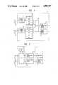
- FIG. 1is a functional block of an embodiment of the present invention
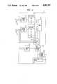
- FIG. 2is a block diagram showing a hard construction of the present invention
- FIGS. 3 and 4show examples of display on an operation display portion thereof
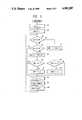
- FIG. 5is a flowchart for explanation of an operation of a microcomputer of this embodiment
- FIG. 6is a functional block diagram of a second embodiment of the present invention.
- FIG. 7is a flowchart for explanation of an operation of a microcomputer of the second embodiment.
- FIGS. 8 and 9show examples of display on an operation display portion.
- FIG. 2is a block diagram of a main portion of the present embodiment.
- the present embodimentincludes a car type selection switch (referred to as CAR key hereinafter) 1-1 which is peferably a push button, a music genre selection switch (referred to as "MJNL key”, hereinafter) 1-2 which is preferably a push button, an equalizer 3, an operation display portion 4 and a microcomputer 2.
- the microcomputer 2includes a CPU 2-1, a RAM 2-2, a serial communication portion 2-3 and a display control portion 2-4.
- FIG. 1A functional block of the microcomputer 2 of the present embodiment is shown in FIG. 1.
- a first address counter 11receives an output of the CAR key 1-1 and a second address counter 13 receives an output of the MJNL key 1-2.
- a car type data memory device 12, a music genre data (referred to as MJNL data) memory device 14, an adder 15 for adding the car type data and the MJNL dataare shown as well as the serial communication portion and the control display portion.
- data(a first group of frequency characteristics) related to compensation for sound characteristics of spatial configulations of different car rooms are stored.
- An example of the data for the frequency characteristicsis shown in Table 1.
- SDN, HTH and CUPrepresent sedan type car, hatchback type car and coupe type car, respectively.
- correction data(second group of frequency characteristics) related to optimum frequency characteristics for musical genre are stored.
- An example of such correction datais shown in Table 2.
- FLTrepresents a flatness in which gains in respective frequency ranges become flat
- POPrepresents pop music
- SNHrepresents synthesized music
- ROCrock music
- FIG. 3shows an example of the operation display portion 4 of this embodiment, which is shown in FIG. 1 and 2.
- Indicatorssuch as lamps or LED's labeled SDN, HTH and CUP on the operation display portion 4 are related to the respective frequency characteristics of the first group, an activation of any one of them showing a selected frequency characteristics for correcting sound characteristics of a specific spatial configulation of car room of a sedan type car, hatchback type car or coupe type car, respectively.
- indicators labeled FLT, POP, SNH and ROCare related to the respective frequency characteristics of the second group, an activation thereof showing a selected frequency characteristics providing a flat gain in the frequency range or frequency characteristics optimum for pop music, synthesized music or rock music.
- a car type frequency characteristics HTH(hatchback) is selected from the first group of frequency characteristics stored in the RAM 2-2, i.e., the car type data memory device 12 of the micro computer 2.
- This characteristics HTHhas values shown in Table 1. These values and the characteristics of FLT of the second group of frequency characteristics which has been set preliminally are added in the adder 15, a result being sent to the serial communication portion 2-3.
- the serial communication portion 2-3converts this sum into a suitable data form and transfers it to the equalizer 3. Upon this, a frequency characteristics of a reproducd sound is changed to a desired frequency characteristics for the hatchback type car room.
- a display on the operation display portion 4becomes as shown in FIG. 4.
- the 6th lineindicates a 0 level and each level shift from the 0 level line indicates a level change of 2. That is, the 5th level is +2 level and the 7th level is -2 level. For the levels higher than +10 and lower than -10, they are displayed as the top level and the bottom level, respectively.
- FIG. 5shows only portions which are necessary to explain the operation of this embodiment, the remaining portions being omitted.
- the first and the second adderss counters 11 and 13are set with initial values 1 in the steps S1 and S2, respectively.
- step S3it is checked in the step S3 whether the CAR key 1-1 is depressed. If no, then it is checked in the step S4 whether the MJNL key 1-2 is depressed. If no, the operation is shifted to the step S8.
- the data of the SDN, HTH or CUP of the car type data memory 12is accessed, respectively, while, when the value of the second address counter 13 is 1, 2, 3 or 4, the data of FLT, POP, SNH or ROC of the MJNL data memory 14 is accessed, respectively.
- step S9the data of the composite frequency characteristics f0 is transmitted to the equalizer 3 to make the audio apparatus ready to reproduce the composite frequency characteristics of the SDN and FLT.
- a display operation on the operation display portion 4is performed in the step S10 to obtain a display shown in FIG. 3.
- step S3when the decision in the step S3 is yes, that is, the CAR key 1-1 is depressed, the value of the address counter 11 is incremented by 1 in the step S11, resulting in a value 2 set in the counter 11.
- step S12it is checked whether the content of the address counter 11 is 4. Since it is no because the current value of the address counter 11 is 2, the counter value 2 is kept unchanged. If the decision in the step S12 is yes, the operation is moved to the step S13 to reset the address counter 11 to 1.
- step S8the composite frequency characteristics f0 of HTH and FLT is obtained in the similar way to that mentioned previously and, in the step S9, the frequency characteristics f0 is transferred to the equalizer 3. Further, in the step S10, a display output is sent to the operation display portion 4, so that the display shown in FIG. 3 is changed to that shown in FIG. 4.
- the decision in the step S4is yes, that is, the MJNL key 1-2 is depressed
- the second address counter 13is incremented by 1 through the steps S5, S6 and S7, similarly, to change the frequency characteristics from the current state of FLT to a preceding POP.
- the composite frequency characteristics of HTH and POPis obtained.
- the frequency characteristics to the equalizer 3is set and, in the step S10, a display output is sent to the operation display portion.
- FIG. 6shows a functional block of the microcomputer 2 shown in FIG. 1 according to a second embodiment of the present invention.
- FIG. 6a first data selection portion 2-5, a second data selection portion 2-6 and a 5 second timer 2-7 are added to the first embodiment shown in FIG. 1.
- a difference of this embodiment from the first embodimentis that, when either the CAR key 1-1 or the MJNL key 1-2 is depressed to perform the change of frequency characteristics, sound having frequency characteristics assigned by the CAR key or the MJNL key can be listened for a certain time period, say, 5 seconds, and subsequently a sound having a composite frequency characteristics obtained as mentioned previously is available. Thus, it is possible to recognize a difference in the reproduced sound therebetween.
- the 5 second timer 2-7is inactive and the second data selection portion 2-6 selects the data of the adder portion 15 and sends them to the serial communication portion 2-3 and to the display control portion 2-4.
- the operationis shifted from the step S4 to the step S5 in which the address counter 13 is incremented by 1, resulting in the content of the address counter 13 being 2. Then, since the decision in the step S6 is no because the current value of the counter 13 is 2, the value of the address counter 13 remains 2.
- the value 2 of the address counter 13is transferred, in the step S8, to the equalizer 3 in which the frequency characteristics for POP corresponding to this value is set. Further, in the step S13, the POP frequency characteristics is displayed on the operation display portion 4. The setting and display of this POP frequency characteristics are performed in the step S14 for a certain time, in this embodiment, for 5 seconds. The display in this case becomes as shown in FIG. 8.
- the first data selection portion 2-5operates to select the data in the MJNL data memory device 14.
- the 5 second timer 2-7is actuated and the second data selection portion 2-6 selects an output of the first data selection portion for 5 seconds. Therefore, the POP frequency characteristics is sent to the serial communication portion 2-3 and the display control portion 2-4 as mentioned previously.
- the operationis shifted to the step S15 to obtain a composite frequency characteristics f0 of the unchanged car type frequency characteristics data f1 and the changed MJNL type frequency characteristics data f2 obtained in the step S16.
- the composite frequency characteristics f0is serially transferred to and set in the equalizer 3 in the step S16 and displayed on the operation display portion 4 in the step S17, similarly.
- the displayin this case bacomes as shown in FIG. 9.
- the operationis shifted to the step S9 in which the first address counter 11 is incremented by 1.
- the frequency characeristics data f1 corresponding to a car of the type assigned by the address counter 11is serially transferred to the equalizer 3 in the step S12 and displayed in the step S13.
- This stateis maintained for 5 seconds in the step S14 and thereafter the operation is shifted to the step S15 in which the operations for obtaining the composite frequency characteristics f0, for transferring this to the equalizer 3 in the step S16 and displaying this on the operation display portion 4 in the step S17 are performed, as in the previous case.
- the first data selection portion 2-5 in FIG. 6selects the output of the car type data memory device 12 and the second data selection portion 2-6 selects the output data of the first data selection portion 2-5 for 5 seconds given by the 5 second timer 2-7 and sends it to the serial communication portion 2-3 and the display control portion 2-4. It is clear that the second data selection portion 2-6 selects the output of the adder portion 15 and sends it to the serial communication portion 2-3 and the display control portion 2-4 after the 5 second timer becomes inoperative.
Landscapes
- Tone Control, Compression And Expansion, Limiting Amplitude (AREA)
- Control Of Amplification And Gain Control (AREA)
Abstract
Description
TABLE 1 ______________________________________ frequency (Hz)car type 60 250 1K 3.3K 10K ______________________________________ SDN +10 0 0 0 +10 HTH +8 -2 +4 0 +4 CUP +6 -4 0 0 +10 ______________________________________
TABLE 2 ______________________________________ frequency (Hz)genre 60 250 1K 3.3K 10K ______________________________________ FLT 0 0 0 0 0 POP 0 +4 +8 +4 0 SNH +4 0 -2 +2 +4 ROC +8 +4 0 -2 0 ______________________________________
Claims (6)
Applications Claiming Priority (2)
| Application Number | Priority Date | Filing Date | Title |
|---|---|---|---|
| JP63-151138 | 1988-06-21 | ||
| JP15113888AJP2649948B2 (en) | 1988-06-21 | 1988-06-21 | Audio device with electronic glyco |
Publications (1)
| Publication Number | Publication Date |
|---|---|
| US4903307Atrue US4903307A (en) | 1990-02-20 |
Family
ID=15512199
Family Applications (1)
| Application Number | Title | Priority Date | Filing Date |
|---|---|---|---|
| US07/365,828Expired - LifetimeUS4903307A (en) | 1988-06-21 | 1989-06-14 | Audio apparatus having electronic graphic equalizer |
Country Status (3)
| Country | Link |
|---|---|
| US (1) | US4903307A (en) |
| EP (1) | EP0347719B1 (en) |
| JP (1) | JP2649948B2 (en) |
Cited By (21)
| Publication number | Priority date | Publication date | Assignee | Title |
|---|---|---|---|---|
| US5119420A (en)* | 1989-11-29 | 1992-06-02 | Pioneer Electronic Corporation | Device for correcting a sound field in a narrow space |
| US5146507A (en)* | 1989-02-23 | 1992-09-08 | Yamaha Corporation | Audio reproduction characteristics control device |
| US5263188A (en)* | 1991-08-16 | 1993-11-16 | Delco Electronics Corporation | Fade compensated tone control method and apparatus |
| US5271063A (en)* | 1990-11-19 | 1993-12-14 | Staar S.A. | Controls for a vehicle audio/video apparatus |
| US5434923A (en)* | 1990-08-07 | 1995-07-18 | Kabushiki Kaisha Kenwood | Acoustic apparatus |
| US5446505A (en)* | 1989-05-06 | 1995-08-29 | Daewoo Electronics Co., Ltd. | Color television system having broadcast program adaptive video/audio adjustment apparatus |
| US5680468A (en)* | 1995-02-21 | 1997-10-21 | Chrysler Corporation | Methods of and systems for speaker equalization in automotive vehicles having convertible tops |
| US5745583A (en)* | 1994-04-04 | 1998-04-28 | Honda Giken Kogyo Kabushiki Kaisha | Audio playback system |
| US6195438B1 (en)* | 1995-01-09 | 2001-02-27 | Matsushita Electric Corporation Of America | Method and apparatus for leveling and equalizing the audio output of an audio or audio-visual system |
| US20030028385A1 (en)* | 2001-06-30 | 2003-02-06 | Athena Christodoulou | Audio reproduction and personal audio profile gathering apparatus and method |
| US6704421B1 (en)* | 1997-07-24 | 2004-03-09 | Ati Technologies, Inc. | Automatic multichannel equalization control system for a multimedia computer |
| US20040091123A1 (en)* | 2002-11-08 | 2004-05-13 | Stark Michael W. | Automobile audio system |
| US20040114771A1 (en)* | 2002-12-12 | 2004-06-17 | Mitchell Vaughan | Multimedia system with pre-stored equalization sets for multiple vehicle environments |
| US20040247141A1 (en)* | 2003-06-09 | 2004-12-09 | Holmi Douglas J. | Convertible automobile sound system equalizing |
| US20050100174A1 (en)* | 2002-11-08 | 2005-05-12 | Damian Howard | Automobile audio system |
| US20060013423A1 (en)* | 2004-07-13 | 2006-01-19 | Wieczorek Alfred B | Method and system for selective coupling of a communication unit to a hearing enhancement device |
| US20090110210A1 (en)* | 2007-10-29 | 2009-04-30 | Bose Corporation | Vehicle Audio System Including Door-Mounted Components |
| US20100169945A1 (en)* | 2008-12-31 | 2010-07-01 | Echostar Technologies L.L.C. | Virtual Control Device |
| US7805751B1 (en)* | 2004-04-28 | 2010-09-28 | Michael T Dugan | Automatic reconfiguration device |
| US9043006B2 (en) | 2012-07-27 | 2015-05-26 | Alpine Electronics, Inc. | Acoustic characteristics setting support system and acoustic characteristics setting apparatus |
| US9210356B2 (en) | 2008-12-08 | 2015-12-08 | Echostar Technologies L.L.C. | System and method for entertainment system reconfiguration |
Families Citing this family (6)
| Publication number | Priority date | Publication date | Assignee | Title |
|---|---|---|---|---|
| JPH03278603A (en)* | 1990-03-28 | 1991-12-10 | Kenwood Corp | Graphic equalizer |
| DE69616139T2 (en)* | 1995-04-25 | 2002-03-14 | Matsushita Electric Industrial Co., Ltd. | System for adjusting the sound quality |
| JP2907066B2 (en)* | 1995-08-03 | 1999-06-21 | 松下電器産業株式会社 | Input device for sound quality adjustment device |
| US7123728B2 (en)* | 2001-08-15 | 2006-10-17 | Apple Computer, Inc. | Speaker equalization tool |
| JP2006068070A (en)* | 2004-08-31 | 2006-03-16 | Aruze Corp | Game machine |
| JP4579215B2 (en)* | 2006-09-21 | 2010-11-10 | アルパイン株式会社 | Audio apparatus and sound quality correction method for audio apparatus |
Citations (3)
| Publication number | Priority date | Publication date | Assignee | Title |
|---|---|---|---|---|
| US4458362A (en)* | 1982-05-13 | 1984-07-03 | Teledyne Industries, Inc. | Automatic time domain equalization of audio signals |
| US4559569A (en)* | 1983-03-08 | 1985-12-17 | Thomson-Brandt | Circuit arrangement for correcting frequency response in accordance with frequency response of a sound field |
| US4661982A (en)* | 1984-03-24 | 1987-04-28 | Sony Corporation | Digital graphic equalizer |
Family Cites Families (1)
| Publication number | Priority date | Publication date | Assignee | Title |
|---|---|---|---|---|
| JPS5718110A (en)* | 1980-07-09 | 1982-01-29 | Arupain Kk | Equalizer device |
- 1988
- 1988-06-21JPJP15113888Apatent/JP2649948B2/ennot_activeExpired - Lifetime
- 1989
- 1989-06-13EPEP89110667Apatent/EP0347719B1/ennot_activeExpired - Lifetime
- 1989-06-14USUS07/365,828patent/US4903307A/ennot_activeExpired - Lifetime
Patent Citations (3)
| Publication number | Priority date | Publication date | Assignee | Title |
|---|---|---|---|---|
| US4458362A (en)* | 1982-05-13 | 1984-07-03 | Teledyne Industries, Inc. | Automatic time domain equalization of audio signals |
| US4559569A (en)* | 1983-03-08 | 1985-12-17 | Thomson-Brandt | Circuit arrangement for correcting frequency response in accordance with frequency response of a sound field |
| US4661982A (en)* | 1984-03-24 | 1987-04-28 | Sony Corporation | Digital graphic equalizer |
Cited By (33)
| Publication number | Priority date | Publication date | Assignee | Title |
|---|---|---|---|---|
| US5146507A (en)* | 1989-02-23 | 1992-09-08 | Yamaha Corporation | Audio reproduction characteristics control device |
| US5446505A (en)* | 1989-05-06 | 1995-08-29 | Daewoo Electronics Co., Ltd. | Color television system having broadcast program adaptive video/audio adjustment apparatus |
| US5119420A (en)* | 1989-11-29 | 1992-06-02 | Pioneer Electronic Corporation | Device for correcting a sound field in a narrow space |
| US5434923A (en)* | 1990-08-07 | 1995-07-18 | Kabushiki Kaisha Kenwood | Acoustic apparatus |
| US5271063A (en)* | 1990-11-19 | 1993-12-14 | Staar S.A. | Controls for a vehicle audio/video apparatus |
| US5263188A (en)* | 1991-08-16 | 1993-11-16 | Delco Electronics Corporation | Fade compensated tone control method and apparatus |
| US5745583A (en)* | 1994-04-04 | 1998-04-28 | Honda Giken Kogyo Kabushiki Kaisha | Audio playback system |
| US6195438B1 (en)* | 1995-01-09 | 2001-02-27 | Matsushita Electric Corporation Of America | Method and apparatus for leveling and equalizing the audio output of an audio or audio-visual system |
| US5680468A (en)* | 1995-02-21 | 1997-10-21 | Chrysler Corporation | Methods of and systems for speaker equalization in automotive vehicles having convertible tops |
| US6704421B1 (en)* | 1997-07-24 | 2004-03-09 | Ati Technologies, Inc. | Automatic multichannel equalization control system for a multimedia computer |
| US20030028385A1 (en)* | 2001-06-30 | 2003-02-06 | Athena Christodoulou | Audio reproduction and personal audio profile gathering apparatus and method |
| US20080117070A1 (en)* | 2002-11-08 | 2008-05-22 | Bose Corporation | Automobile Audio System |
| US20050100174A1 (en)* | 2002-11-08 | 2005-05-12 | Damian Howard | Automobile audio system |
| US20040091123A1 (en)* | 2002-11-08 | 2004-05-13 | Stark Michael W. | Automobile audio system |
| US20080117038A1 (en)* | 2002-11-08 | 2008-05-22 | Bose Corporation | Automobile Audio System |
| US7724909B2 (en) | 2002-11-08 | 2010-05-25 | Stark Michael W | Automobile audio system |
| US20080122602A1 (en)* | 2002-11-08 | 2008-05-29 | Westley Brandon B | Automobile Audio System |
| US7483539B2 (en) | 2002-11-08 | 2009-01-27 | Bose Corporation | Automobile audio system |
| US7957540B2 (en) | 2002-11-08 | 2011-06-07 | Bose Corporation | Automobile audio system |
| US20040114771A1 (en)* | 2002-12-12 | 2004-06-17 | Mitchell Vaughan | Multimedia system with pre-stored equalization sets for multiple vehicle environments |
| US7583806B2 (en) | 2003-06-09 | 2009-09-01 | Bose Corporation | Convertible automobile sound system equalizing |
| US20040247141A1 (en)* | 2003-06-09 | 2004-12-09 | Holmi Douglas J. | Convertible automobile sound system equalizing |
| US8341690B2 (en)* | 2004-04-28 | 2012-12-25 | Echostar Corporation | Automatic reconfiguration device |
| US7805751B1 (en)* | 2004-04-28 | 2010-09-28 | Michael T Dugan | Automatic reconfiguration device |
| US20110040856A1 (en)* | 2004-04-28 | 2011-02-17 | Dugan Michael T | Automatic reconfiguration device |
| US7106874B2 (en) | 2004-07-13 | 2006-09-12 | Motorola, Inc. | Method and system for selective coupling of a communication unit to a hearing enhancement device |
| US20060013423A1 (en)* | 2004-07-13 | 2006-01-19 | Wieczorek Alfred B | Method and system for selective coupling of a communication unit to a hearing enhancement device |
| US20090110210A1 (en)* | 2007-10-29 | 2009-04-30 | Bose Corporation | Vehicle Audio System Including Door-Mounted Components |
| US8126187B2 (en) | 2007-10-29 | 2012-02-28 | Bose Corporation | Vehicle audio system including door-mounted components |
| US9210356B2 (en) | 2008-12-08 | 2015-12-08 | Echostar Technologies L.L.C. | System and method for entertainment system reconfiguration |
| US20100169945A1 (en)* | 2008-12-31 | 2010-07-01 | Echostar Technologies L.L.C. | Virtual Control Device |
| US9800837B2 (en) | 2008-12-31 | 2017-10-24 | Echostar Technologies L.L.C. | Virtual control device |
| US9043006B2 (en) | 2012-07-27 | 2015-05-26 | Alpine Electronics, Inc. | Acoustic characteristics setting support system and acoustic characteristics setting apparatus |
Also Published As
| Publication number | Publication date |
|---|---|
| JPH01319312A (en) | 1989-12-25 |
| EP0347719B1 (en) | 1994-11-30 |
| EP0347719A3 (en) | 1991-02-20 |
| EP0347719A2 (en) | 1989-12-27 |
| JP2649948B2 (en) | 1997-09-03 |
Similar Documents
| Publication | Publication Date | Title |
|---|---|---|
| US4903307A (en) | Audio apparatus having electronic graphic equalizer | |
| US5745583A (en) | Audio playback system | |
| JP5380804B2 (en) | Audio signal output device | |
| JPH05102770A (en) | Signal processing circuit in audio equipment | |
| US7110550B2 (en) | Sound system | |
| US20040068402A1 (en) | Digital audio processor | |
| KR100230102B1 (en) | How to adjust the volume according to the volume level | |
| US5271063A (en) | Controls for a vehicle audio/video apparatus | |
| US6411335B1 (en) | Image reproducing apparatus and method for setting and automatically changing audio and visual settings for a plurality of channels | |
| EP1061655B1 (en) | An audio system conducting digital signal processing, and a control method thereof | |
| JPH10145157A (en) | Display device for sound volume | |
| US10506340B2 (en) | Digital signal processor for audio, in-vehicle audio system and electronic apparatus including the same | |
| JPS6184200A (en) | Automatic correcting device of sound field | |
| JP2694041B2 (en) | Sound equipment | |
| JPS63177699A (en) | Acoustic device for automobile | |
| JP2001301536A (en) | Main unit of on-vehicle audio device | |
| JP2004064172A (en) | Audio playback device | |
| JP4747830B2 (en) | Audio apparatus and output switching method | |
| KR920007750Y1 (en) | Audio speaker system having multi-surround speakers | |
| JPH10261928A (en) | Graphic equalizer and its adjustment method | |
| JPH03274914A (en) | Audio equipment | |
| KR100203308B1 (en) | Adjustable voice level integrated reproduction control device of television and method thereof | |
| JPH01164111A (en) | Sound characteristic control device | |
| JPH07284185A (en) | Audio player | |
| JPH0718181Y2 (en) | Graphic equalizer |
Legal Events
| Date | Code | Title | Description |
|---|---|---|---|
| AS | Assignment | Owner name:HITACHI AUTOMOTIVE ENGINEERING COMPANY, JAPAN Free format text:ASSIGNMENT OF ASSIGNORS INTEREST.;ASSIGNORS:OZAWA, HIROSHI;HORII, SHIRO;HONDO, ICHIRO;REEL/FRAME:005090/0222 Effective date:19890317 Owner name:HITACHI, LTD., JAPAN Free format text:ASSIGNMENT OF ASSIGNORS INTEREST.;ASSIGNORS:OZAWA, HIROSHI;HORII, SHIRO;HONDO, ICHIRO;REEL/FRAME:005090/0222 Effective date:19890317 | |
| STCF | Information on status: patent grant | Free format text:PATENTED CASE | |
| FPAY | Fee payment | Year of fee payment:4 | |
| FEPP | Fee payment procedure | Free format text:PAYOR NUMBER ASSIGNED (ORIGINAL EVENT CODE: ASPN); ENTITY STATUS OF PATENT OWNER: LARGE ENTITY | |
| FPAY | Fee payment | Year of fee payment:8 | |
| FEPP | Fee payment procedure | Free format text:PAYOR NUMBER ASSIGNED (ORIGINAL EVENT CODE: ASPN); ENTITY STATUS OF PATENT OWNER: LARGE ENTITY Free format text:PAYER NUMBER DE-ASSIGNED (ORIGINAL EVENT CODE: RMPN); ENTITY STATUS OF PATENT OWNER: LARGE ENTITY | |
| REFU | Refund | Free format text:REFUND - PAYMENT OF MAINTENANCE FEE, 12TH YEAR, LARGE ENTITY (ORIGINAL EVENT CODE: R185); ENTITY STATUS OF PATENT OWNER: LARGE ENTITY | |
| FPAY | Fee payment | Year of fee payment:12 |