US4903292A - System for transmitting low frequency tones through a digital loop carrier system - Google Patents
System for transmitting low frequency tones through a digital loop carrier systemDownload PDFInfo
- Publication number
- US4903292A US4903292AUS07/265,718US26571888AUS4903292AUS 4903292 AUS4903292 AUS 4903292AUS 26571888 AUS26571888 AUS 26571888AUS 4903292 AUS4903292 AUS 4903292A
- Authority
- US
- United States
- Prior art keywords
- tone
- analog signal
- signal
- amplitude
- low frequency
- Prior art date
- Legal status (The legal status is an assumption and is not a legal conclusion. Google has not performed a legal analysis and makes no representation as to the accuracy of the status listed.)
- Expired - Lifetime
Links
Images


Classifications
- H—ELECTRICITY
- H04—ELECTRIC COMMUNICATION TECHNIQUE
- H04M—TELEPHONIC COMMUNICATION
- H04M11/00—Telephonic communication systems specially adapted for combination with other electrical systems
- H04M11/06—Simultaneous speech and data transmission, e.g. telegraphic transmission over the same conductors
- H04M11/062—Simultaneous speech and data transmission, e.g. telegraphic transmission over the same conductors using different frequency bands for speech and other data
Definitions
- This inventionconcerns itself generally with the transmission of low frequency sub-audible tones over digital loop carrier, and related thereto, with providing alarm services over digital loop carrier (DLC). More specifically, it is concerned with the transmission of alarm related signals over DLC channels which simultaneously provide facilities for the subscriber's normal residence or business plain ordinary telephone service (POTS).
- DLCdigital loop carrier
- the specific type of alarm reporting and collecting system concernedtransmits a pilot tone, at a frequency in the sub-audible range below the normal voice band, as an "all is well" indication to scanning equipment in the central office.
- the scanning equipmentcommunicates with the subscriber terminal unit (STU) provided by an alarm company at the subscriber's premises by means of bi-directional frequency shift keying (FSK) data transmission, using carrier frequencies at the upper end of the telephone voice band, in the 2700 to 3000 Hz range.
- STUsubscriber terminal unit
- FSKfrequency shift keying
- the subscriberdoes not wish to be bothered by these audible tones when engaged in conversation or non-alarm related data transmission, or at least wants the frequency of their occurrence to be substantially reduced. Accordingly, when the subscriber is off-hook and low tone is present, the scanner either does not attempt to communicate with the STU at all, or only polls it at much longer intervals. If an alarm is registered by the STU, the STU cuts its low tone, and the scanner, on detection of low tone loss, scans the off-hook line. The scanner, or equipment associated with it, passes the alarm indication to the alarm company, which then initiates further communication with the STU, via the scanner, using the previously mentioned FSK data signals, with the central office located equipment relaying the information.
- this alarm serviceuses the same transmission facilities as the subscriber's POTS service, it can be provided more cheaply than more conventional alarm systems such as McCulloh loops, which require a separate, dedicated facility. Prior to the present invention, however, this service could not be provided over DLC channels because they have excessive transmission losses at the low tone frequency, and often do not provide bidirectional voice frequency transmission in the on-hook state. Since the use of DLC by telephone companies to provide POTS is increasing rapidly, the incompatibility of conventional DLC channels with this type of alarm service is becoming increasingly troublesome to them. If a subscriber is currently served via DLC when the alarm service is ordered, they must either deny service, or switch the subscriber to a more expensive metallic facility, if in fact one is available.
- a one-way transmission path at the low tone frequency, with acceptable transmission loss,must be provided in both the on-hook and off-hook states, from the STU to the CO through the DLC channel,
- a two-way voice band path for transmission of the FSK signalsmust be maintained, both in the on-hook and the off-hook states, through the DLC channel. It is a general requirement that DLC systems provide a two-way voice frequency transmission path at all times on non-concentrated channels.
- any modification to the DLC so that it is compatible with such alarm servicebe in the form of circuitry which can be added as needed to both the subscriber and central office portions of the DLC. It is also desirable that any such added circuitry not impair the performance of the two-way path in the DLC. It is further desirable that any such circuitry not respond to the low tone in any way other than to ensure that it can be transmitted "as is" from the remote terminal to the central office. The circuitry will then not cause a spurious signals to be received which indicates the presence of the low tone when the same is not present.
- the system of the present inventionnot only allows the DLC to be compatible with such alarm service and meets the other requirements described above but is also in the form of circuitry that can be added to the DLC when needed.
- a digital loop carrierwhich has two ends and a transmission media connecting the ends.
- the first endhas a circuit which passes to its output only that part of an analog signal at its input which is in a predetermined frequency band.
- the first endalso has a circuit which passes only a tone in the analog signal which has a frequency below the predetermined frequency band.
- the tone passing circuitalso controls the amplitude of the tone to fall within a predetermined amplitude range.
- the first endalso has a circuit which responds to the analog signal at the output of the first circuit and the amplitude controlled tone for encoding the analog signal and tone into a digital signal for transmission by the transmission media to the second end.
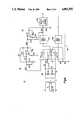
- FIG. 1is a block diagram of a typical digital loop carrier system that also includes an alarm system.
- FIG. 2is a block diagram of the remote terminal of the typical digital loop carrier system which is alarm system compatible in accordance with the present invention.
- FIG. 3is a block diagram of the central office terminal of the typical digital loop carrier system which is alarm system compatible in accordance with the present invention.
- FIG. 4is a simplified schematic circuit diagram for the remote terminal of FIG. 2.
- FIG. 5is a simplified schematic circuit diagram for the central office terminal of FIG. 3.
- FIG. 1shows a block diagram of a telephone circuit 10 embodied in accordance with the present invention for furnishing the above described alarm service with a DLC channel interposed.
- the STU 12which monitors its alarm inputs and communicates with the central office located alarm equipment, and through it with the alarm agency, is connected to the tip (T) and ring (R) conductors of the telephone cable pair 16 in parallel with a telephone 14.
- Ttip
- Rring
- the customer premisesis connected to the remote channel unit (RT) 18 of the DLC by means of cable pair 16 which can range in length from very short to 12 kilofeet.
- the DLC channel unit 18has an interface with the DLC common equipment 20 which processes signals received from the channel unit as required, and then delivers them to the transmission media 19 in suitable form.
- the common equipmentalso proceeds signals received from the transmission media 19 as required, and delivers them to the channel unit in suitable form.
- the transmission media 19 between the DLC remote terminal (RT) and DLC central office terminal (COT) 22may be copper pairs, optical fibers, a radio link, or other media.
- the low toneis processed in the channel unit 18, and delivered with the voice signals to the common equipment 20 for transmission to the central office.
- the COT DLC channel unit 22has an interface, similar to that existing at the remote location, with the DLC system COT common equipment 21 which is connected to the transmission media.
- the central office side of the COT channel unit 22is connected to both the central office switching equipment 24 and the alarm receiving equipment 26.
- the low tone signalis recovered and processed by the channel unit 22, and then delivered to the alarm receiving equipment 26 at a suitable voltage level.
- the alarm receiving equipmentcontains means for detecting the low tone, for transmitting and receiving FSK signals between itself and the STU, and for communicating with the alarm agency.
- the scheme used in North America, excluding Mexico, for encoding analog signals into digital form for transmission over the public networkis called mu255. It employs a 15 segment companding law, and has an approximately 72 dB dynamic range.
- a reference digital signal, the digital milliwatt,has been defined.
- the digital milliwattwhen decoded by an ideal zero level decoder, will produce a zero dBm, 1000 Hz sinusoidal signal into the reference impedance of the decoder.
- the highest level sinusoidal signal which can be encoded by an ideal zero level encoderis +3.17 dBm.
- a signal with a peak value less than that of a sinusoid at approximately -69dBmhas no effect on the output of a zero level encoder and will not be encoded at all.
- a digital signalhas an equivalent power of X dBm (X EdBm), if when decoded by a zero level decoder it produces an analog signal at X dBm.
- the frequency response, with respect to 1000 Hz loss, for a digital transmission system intended for POTS,is generally required to be flat ⁇ 1 dB from 400 to 2800 Hz, with the requirement generally being allocated 50% to each end, and at least 20 dB down at 60 Hz, considering the transmitting end only.
- Commercially available low frequency integrated circuit filters used for this purposeare generally quite flat from 300 to 3000 Hz, down 1.25 to 1.5 dB at 3400 Hz, down perhaps one dB at 200 Hz transmit only, and down much more than 20 dB at 60 Hz and below transmit only.
- the low frequency filtersare at least 14 dB down at 4000 Hz, and at least 32 dB down (transmit) or 28 dB down (receive) at 4600 Hz.
- the transformers used to couple the electronics to the subscriber or CO linealso introduce substantial losses at frequencies of 60 Hz and below.
- the above described low frequency filter and transformer characteristicsare the primary reason for the inability of digital transmission systems to pass very low frequency signals; the mu255 companding law, per se, imposes no low frequency restrictions.
- the requirement for good rejection at 60 Hzstems from the fact that currents at this frequency are nearly always longitudinally induced at some level, no matter how low, into the telephone conductors from the commercial power system.
- the limited dynamic range and other non-linearities of digital systemscan enhance the noise which results from these currents, compared with the noise which would have been produced in a completely linear system with equal longitudinal-to-metallic balance.
- the background noise in the channelis too low to encode without any induced AC being present.
- a low level 60 Hz signalbe introduced such that the noise plus 60 Hz just crosses the first, or first several decision thresholds of the encoder at or near the peaks of the 60 Hz signal.
- the noisebecomes encodeable near the peaks of the 60 Hz signal, or with increasing 60 Hz interference, a combination of noise and 60 Hz is encoded.
- bursts of noiseare transmitted at a 60 Hz rate. This manifests itself as an audible 60 Hz raspiness.
- the unwanted signalis basically voiceband noise interrupted at a 60 Hz rate, it passes through the receiving circuits and transformers at the distant end practically unattenuated, which the 60 Hz itself could not have done.
- the interfering levelwere higher, the effect would be less objectionable, since the 60 Hz would be accurately encoded, very little distortion would be produced, and the entire system from end to end would behave in a more linear fashion. If the 60 Hz level were further increased, a point would be reached at which the quantizing distortion of the 60 Hz signal would become objectionable, even though the fundamental itself might not be. Quantizing distortion due to low frequency signals is generally more troublesome than that due to higher frequencies, since more of its components fall in band, and cannot be filtered out. Since induced 60 Hz levels are not controlled, and it is an unwanted signal to begin with, it is clear that attempting to prevent 60 Hz signals from being encoded is a reasonable strategy.
- the low toneis coupled to a narrowband filter, to reject all signals except a narrow band centered at the low tone frequency.
- the transmitting low tone filterhas sufficient rejection at 60 Hz to assure that the 60 Hz relative attenuation requirement is met.
- the low toneis then reduced to a suitable level for encoding and combined with the void frequency signals emerging from the normal voice frequency bandpass filter.
- the composite signalsis then encoded.
- the output of the normal voice frequency low pass and sample and hold compensation filteris applied to a second narrowband filter to permit the extraction and selective amplification of the attenuated low tune signal.
- the filtered amplified low tone signalis then combined with the other voice signals and transmitted through the voiceband line interface to the CO switching equipment and alarm collecting equipment.
- the low tone frequencyis 36.075 Hz, hereinafter to be referred to as 36 Hz, but it will be understood that the embodiment can be adapted to other frequencies simply by changing component values.
- FIGS. 4 and 5The circuit schematic for the preferred embodiment of the invention is illustrated in FIGS. 4 and 5 with block diagrams therefor being shown in FIGS. 2 and 3, respectively. It will be seen that the topology of the low tone transmission and combining circuitry is identical at both the RT and COT, a development permitting use of identical printed wiring arrangements for those circuit parts at both the COT and RT.
- RT 18includes line interface and access circuit 28 which is connected to the T and R conductors to receive both the voiceband signals and the low tone to be transmitted to the central office.
- Circuit 28has one output connected to the input of low tone filter and level control circuit 30.
- Circuit 28has another output connected to the input of transmit voiceband filter and level control circuit 32a.
- Circuit 30is a narrowband bandpass filter centered at the 36 Hz frequency of the low tone to reject signals which are not the low tone. Circuit 30 also provides control of the amplitude level of the low tone so as to ensure that its encoded level falls within the amplitude window described above.
- Circuit 32ais a low pass filter whose passband is in the telephone voiceband to reject signals which are not in the telephone voiceband. Therefore, circuit 32 rejects the low tone from the signal at its input while circuit 30 rejects voiceband signals from its input signal. Circuit 32a also provides control of the amplitude level of the voiceband signals. Circuits 30 and 32a both reject 60 Hz signals.
- circuit 30 and 32aare both connected to the input of combining and level control circuit 34.
- Circuit 34functions to combine the filtered and level controlled low tone with the filtered and level controlled voiceband signals.
- Circuit 34provides a fine adjustment to the level controls provided by circuits 30 and 32a.
- the output of circuit 34is connected to the RT common equipment 20 which among other things encodes the combined low tone and voiceband signals for transmission to the central office.
- the level of the low tone in the combined signalsis such that the encoded level is within the previously described amplitude window. It should further be appreciated that while circuit 34 has been described as providing level control to the combined signal, that all such control can be provided by circuits 30 and 32a.
- Receive voiceband filter and level control circuit 32bis not associated with the transmission of the low tone. As described above, the low tone is transmitted only from the subscriber to the central office. Therefore, circuit 32b functions in a manner identical to the receive voiceband filter and level control circuit in the RT of a DLC which does not have the alarm system compatibility of the present invention.
- COT 22includes receive voiceband filter circuit 38a.
- the encoded composite low tone and voiceband signal received at the central office from the subscriberis first decoded into PAM samples by the COT common equipment 21.
- the PAM samplesare then reconstructed by a sample and hold circuit into a stair step approximation to the original signal encoded at the RT.
- Receive voiceband filter circuit 38areconstructs the encoded composite low tone and voiceband signal by both removing any distortion introduced by the sample and hold circuit and any high frequency components in the stair step approximation.
- Circuit 40has a narrow passband centered about the low tone frequency to thereby reject all frequencies in the combined signal other than the low tone. Circuit 40 also provides gain to the low tone to substantially increase its amplitude as compared to the low tone amplitude at the output of circuit 38a.
- circuits 38 and 40are both received at the input to combining and level control circuit 42.
- Circuit 42recombines the amplified and filtered low tone from circuit 40 with the combined signal from circuit 38a.
- Circuit 42also provides appropriate level control so that the low tone is delivered to the interface circuit 44 with the proper level.
- the transmission path in COT 22is not associated with the low tone. Therefore, transmit voiceband filter and level control circuit 38b functions in a manner identical to the same circuit in a DLC which does not have the alarm system compatibility of the present invention.
- FIG. 4there is shown a simplified schematic diagram for that part of RT 18 which is associated with transmission of the low tone and voiceband signals to the central office.
- the low tone and voiceband signalsare coupled through transformer T 1 to the two wire to four wire hybrid formed by resistors R3, R4, R6 and R7, and the amplifiers inside the integrated circuit (IC) chip which has been used to implement the voiceband filter and level control circuit 32.
- ICintegrated circuit
- circuit 32includes a transmit voiceband bandpass filter 32a, a receive voiceband lowpass filter 32b and operational amplifiers 32c, 32d and 32e.
- the low tone and voiceband signalsare connected to amplifier 32d which functions as an inverting amplifier.
- the input to the low frequency narrowband filter and level control circuit 30is connected to the output of inverting operational amplifier 32d.
- the output of amplifier 32dis also connected to the input of circuit 32a which functions to band limit the voiceband signals.
- the bandpass characteristics of circuit 32aseverely attenuate the low tone.
- Circuit 30acts as a low tone filter and provides level control to the low tone so that the encoded level of the low tone falls within the amplitude window.
- Operational amplifier A1 and associated components, i.e., resistors R17, R18, R19, R20, R21 and R25, and capacitors C5 and C6, of circuit 30function as the low tone bandpass filter.
- the resistance of resistor R25is selected to fine tune the filter center frequency.
- the transformer T 1is selected to have a reasonably large and fairly constant inductance. These characteristics make is possible to internally access the voiceband path in order to deliver the low tone signal to the 36 Hz filter 30. Since the IC 32 is powered by ⁇ 5V, and the low tone filter 30 is powered by ⁇ 12V, the low tone filter 30 cannot be overloaded. The output of the transmitting amplifier in the IC, therefore, drives both the transmit voiceband bandpass filter 32a and the 36 Hz bandpass filter.
- 36 Hz levels at all points, and to voiceband signal levels at points interior to the RT or COT channel unitsthe following convention is adopted:
- a low tone signal applied to the T and R terminals at -27 dBtypically appears at the low tone filter input at -38 dB.
- the filter 30is operated at 3.5 dB loss.
- Circuit 34is embodied in the form of a combining amplifier A2.
- the output of filter 30is connected to the input of amplifier A2 through resistor R22.
- the output of IC 32is connected to the input of amplifier A2 through resistor R23.
- the combining amplifier A2is operated in a non-inverting configuration.
- the transmit voiceband bandpass filter 32adrives both the second input of the combining amplifier through resistor R23, and an attenuator (formed by resistors R27 and R28) which is superfluous when the low tone transmission circuitry is provided.
- resistors R22 and R23are selected to be of equal value, they introduce a 6 dB loss at the combining amplifier input, to both the low tone and voiceband inputs.
- the amplifieritself is operated at a 2.5 dB gain, so that the low tone signal emerges at -45 dB, and the 1000 Hz tone emerges at -1.4 dB.
- Circuit 34afunctions both as a buffer and to remove any DC offset in the combined signal. Failure to remove any such offset will adversely affect the encoding of the combined signal.
- the combining amplifierSince the combining amplifier has a near-zero output impedance, the signal driven through resistor R27 from the voiceband bandpass filter 32a is reduced to zero, and only the signals from the combining amplifier output drive the buffer amplifier and dc offset control circuit 34a.
- the 1000 Hz signalafter passing through the buffer amplifier and dc offset control circuit, is encoded at -2 EdBm, so that at 1000 Hz, the output of the combining amplifier is a +0.6 encode level point (ELP), i.e., a voltage level of +0.6 dB causes a digital milliwatt to be encoded.
- ELP+0.6 encode level point
- the buffer amplifier and dc offset control circuitintroduce an additional 2.2 dB loss at 36 Hz, so that the low tone signal is encoded at -47.8 EdBm, which is suitably located in the "amplitude window".
- the 60 Hz signals arriving at the low tone filter outputare typically down 37 dB; those arriving at the output of the transmit voiceband filter are typically down 43 dB. Allowing for the combining amplifier's net 3.5 dB loss, and for an additional one dB of 60 Hz loss in the buffer amplifier and dc offset control circuit, encoded 60 Hz signals are down at least 38 dB, even if they have combined in phase; thus, the 60 Hz rejection requirement (20 dB) is easily met.
- the receive directionis not associated with the low tone transmission path. It is clear that since the RT circuitry is energized at all times in accordance with the general requirement that a DLC maintain a two-way path that a bi-directional voiceband path for FSK signals always exists at and within the RT channel unit. The present invention does not impair the operation of the RT channel unit.
- FIG. 5depicts the simplified schematic diagram for COT channel unit 22 of the present invention.
- Circuit 38is embodied in the form of an integrated circuit (IC) chip which includes a receive lowpass sample and hold compensation filter 38a.
- the IC used to embody circuit 38is the same as the IC used to embody circuit 32 and may, for example, but the type TP 3040 PCM monolithic filter chip available from National Semiconductor Corporation of Santa Clara, Calif.
- a digital milliwattis decoded as a sampled and held voltage of +4 dB.
- the low toneis decoded as -43.8 dB at the input to the receive lowpass sample and hold compensation filter 38a, and emerges from the filter at the same level to drive the low tone bandpass filter 40 embodied in the form of operational amplifier A1, the voiceband input to the combining amplifier A2 through resistor R23, and the attenuator formed by resistors R8 and R9.
- the same reference designatorsare used wherever possible in FIG. 5 for the components of circuit 22 as was used in FIG. 4 for the components of circuit 18 in order to show the functional similarity between circuits 18 and 22.
- the low tone filteris operated at a gain of 20 dB, and the low tone emerges from it at a level of -23.8 dB to drive the low tone input of the combining amplifier through resistor R22.
- resistors R22 and R23are not equal, and serve to adjust the voiceband and low tone signals to the proper relative levels at the input to the combining amplifier.
- Resistors R24 and R26set the gain of the combining amplifier, which compensates for the loss of the combining network formed by resistors R22 and R23, and delivers the low tone signal at a level of -15.6 dB to the center of the voltage divider formed by resistors R8 and R9 at the input to the differential amplifier 38c.
- a 1000 Hz signal applied to the RT at zero levelwould appear at this same point at a level of +0.2 dB.
- the attenuator formed by resistors R8 and R9serves no purpose when the low tone transmission circuitry is provided, and only the signal emanating from the combining amplifier reaches the differential amplifier.
- the differential amplifierimpresses the composite signal on the hybrid circuitry and transformer T1 (selected in the manner described for transformer T1 of FIG. 4), with the result that the low tone is delivered to a 900 ohm termination across T and R terminals at a typical level of -26.3 dBm. Since the low tone signal has been fed through the normal hybrid circuit path, voiceband components which pass through the filter skirts are subjected to a normal transhybrid loss, and the return loss seen looking into the channel unit at the RT is not significantly affected.
- the 36 Hz loss through the transmit voiceband bandpass filter 38bis at least 55 dB, and it alone is more than sufficient to prevent the low tone signal from returning to the RT at significant levels.
- the loss at 36 Hz through the transformer and hybrid circuitryincreases by about 4 dB so that the on-hook loss measured between 900 ohm terminations is about 3.3 dB.
- the low tone input level at the RTtypically increases by 18 dB or so, since the loading effect of the off-hook telephone is eliminated. Accordingly, the level actually increases, rather than decreases at the COT, by about 14 dB, when the COT is terminated in 900 ohms.
- the increase in off-hook levelis usually 17 dB or more.
- the increased transmit level in the on-hook statecauses the encoded low tone signal to exceed the upper limits of the previously mentioned "amplitude window", causing an increase in noise at the COT which might amount to 5 dB or slightly more. Since the channel is not used for conversation in the on-hook state, and since the resulting noise level is far too low to interfere with the FSK signals, the increase in noise is of no consequence.
- Capacitor C1guarantees that a voiceband path through transformer T1 exists in both the on and off-hook states, and since all circuitry is continuously energized in accordance with the general requirement, it is clear that a bidirectional voiceband path is always available for the FSK signals. The present invention does not impair that operation.
- the transmit circuitry at the COTis not involved in the low tone transmission path.
- the filtered and level controlled low toneis combined with the filtered and level controlled voiceband signals prior to being encoded at the RT
- the filtered and level controlled low tone and the filtered and level controlled voiceband signalsmay each be separately encoded at the RT and then the digital signals resulting therefrom combined into a single digital signal for transmission to the central office.
Landscapes
- Engineering & Computer Science (AREA)
- Computer Networks & Wireless Communication (AREA)
- Signal Processing (AREA)
- Interface Circuits In Exchanges (AREA)
Abstract
Description
0 dB means 0.948 VRMS
Claims (20)
Priority Applications (2)
| Application Number | Priority Date | Filing Date | Title |
|---|---|---|---|
| US07/265,718US4903292A (en) | 1988-11-01 | 1988-11-01 | System for transmitting low frequency tones through a digital loop carrier system |
| CA000590153ACA1299790C (en) | 1988-11-01 | 1989-02-03 | System for transmitting low frequency tones through a digital loop carrier system |
Applications Claiming Priority (1)
| Application Number | Priority Date | Filing Date | Title |
|---|---|---|---|
| US07/265,718US4903292A (en) | 1988-11-01 | 1988-11-01 | System for transmitting low frequency tones through a digital loop carrier system |
Publications (1)
| Publication Number | Publication Date |
|---|---|
| US4903292Atrue US4903292A (en) | 1990-02-20 |
Family
ID=23011612
Family Applications (1)
| Application Number | Title | Priority Date | Filing Date |
|---|---|---|---|
| US07/265,718Expired - LifetimeUS4903292A (en) | 1988-11-01 | 1988-11-01 | System for transmitting low frequency tones through a digital loop carrier system |
Country Status (2)
| Country | Link |
|---|---|
| US (1) | US4903292A (en) |
| CA (1) | CA1299790C (en) |
Cited By (52)
| Publication number | Priority date | Publication date | Assignee | Title |
|---|---|---|---|---|
| US5263081A (en)* | 1989-11-01 | 1993-11-16 | Hubbell Incorporated | Method and apparatus for providing on-hook transmission for digital loop carrier channel units |
| EP0535561A3 (en)* | 1991-09-28 | 1995-05-03 | Bosch Telecom | |
| US5528663A (en)* | 1992-06-24 | 1996-06-18 | Siemens Rolin Communication Inc. | DTMF detection for voice processing equipment |
| GB2306818A (en)* | 1995-10-31 | 1997-05-07 | Mitsubishi Electric Corp | Portable analog/digital radio transmitter/receiver with switchable filters |
| US5646940A (en)* | 1992-05-04 | 1997-07-08 | Novi International, Inc. | System for simultaneous analog and digital communications over an analog channel |
| WO1997035418A1 (en)* | 1996-03-20 | 1997-09-25 | Numerex Investment Corporation | Apparatus and method for supervising derived channel communications |
| WO1997039535A3 (en)* | 1996-04-12 | 1997-12-24 | Johnson Co E F | Bandwidth management system for a remote repeater network |
| WO1998048564A1 (en)* | 1997-04-22 | 1998-10-29 | Digital Security Controls Limited | Security system with two signal reporting |
| US5896560A (en)* | 1996-04-12 | 1999-04-20 | Transcrypt International/E. F. Johnson Company | Transmit control system using in-band tone signalling |
| US5901201A (en)* | 1997-05-14 | 1999-05-04 | Bellsouth Corporation | Switch-based line continuity verification method and system |
| US5953374A (en)* | 1997-03-03 | 1999-09-14 | Pc-Tel, Inc. | Bandpass spectral shaping of data signals |
| US5991309A (en)* | 1996-04-12 | 1999-11-23 | E.F. Johnson Company | Bandwidth management system for a remote repeater network |
| US6157640A (en)* | 1996-06-25 | 2000-12-05 | Ericsson Inc | Providing feature logic control in parallel with voice over a single subscriber access |
| US6229886B1 (en)* | 1997-01-22 | 2001-05-08 | Ciena Corporation | Method and apparatus for providing 56K modem technology for public switched telephone networks |
| US20020015203A1 (en)* | 1999-05-11 | 2002-02-07 | Buabbud George H. | Optical communication system for transmitting RF signals downstream and bidirectional telephony signals which also include RF control signals upstream |
| US6353609B1 (en) | 1998-06-19 | 2002-03-05 | Marconi Communications, Inc. | Digital packet network for the local access loop |
| US20020029147A1 (en)* | 1999-02-02 | 2002-03-07 | James Parker | Alarm system using local data channel |
| US6362908B1 (en) | 1998-12-02 | 2002-03-26 | Marconi Communications, Inc. | Multi-service adaptable optical network unit |
| US6404763B1 (en) | 2000-02-11 | 2002-06-11 | General Bandwidth Inc. | System and method for communicating telecommunication information between network equipment and a plurality of local loop circuits |
| US6466573B1 (en) | 2000-02-11 | 2002-10-15 | General Bandwidth Inc. | System and method for communicating telecommunication information between a telecommunication switch and customer premises equipment |
| US6512764B1 (en) | 1999-07-16 | 2003-01-28 | General Bandwidth Inc. | Method and apparatus for providing voice signals to and from a telecommunications switch |
| US6512762B1 (en) | 2000-02-11 | 2003-01-28 | General Bandwidth, Inc. | System and method for communicating telecommunication information between customer premises equipment and network equipment |
| US6526046B1 (en) | 2001-04-24 | 2003-02-25 | General Bandwidth Inc. | System and method for communicating telecommunication information using asynchronous transfer mode |
| US20030128983A1 (en)* | 1999-05-11 | 2003-07-10 | Buabbud George H. | Digital RF return over fiber |
| US20030236916A1 (en)* | 2002-04-23 | 2003-12-25 | Adcox Timothy D. | Media access control address translation for a fiber to the home system |
| US6754221B1 (en) | 2001-02-15 | 2004-06-22 | General Bandwidth Inc. | System and method for selecting a compression algorithm according to an available bandwidth |
| US6781981B1 (en) | 1998-09-11 | 2004-08-24 | Advanced Fibre Access Corporation | Adding DSL services to a digital loop carrier system |
| US6839342B1 (en) | 2000-10-09 | 2005-01-04 | General Bandwidth Inc. | System and method for interfacing signaling information and voice traffic |
| US20050024499A1 (en)* | 2000-07-05 | 2005-02-03 | Luciano Joseph W. | Photoprinter control of peripheral devices |
| US6879667B1 (en) | 2001-05-07 | 2005-04-12 | General Bandwidth Inc. | System and method for interfacing telephony voice signals with a broadband access network |
| US6996134B1 (en) | 2001-05-07 | 2006-02-07 | General Bandwidth Inc. | System and method for reliably communicating telecommunication information |
| US20060072741A1 (en)* | 2003-01-30 | 2006-04-06 | Serconet Ltd | Method and system for providing DC power on local telephone lines |
| US20060092962A1 (en)* | 1998-07-28 | 2006-05-04 | Serconet, Ltd | Local area network of serial intelligent cells |
| US7103907B1 (en) | 1999-05-11 | 2006-09-05 | Tellabs Bedford, Inc. | RF return optical transmission |
| US20060203981A1 (en)* | 2000-03-20 | 2006-09-14 | Serconet Ltd. | Telephone outlet for implementing a local area network over telephone lines and a local area network using such outlets |
| US7149182B1 (en) | 2001-04-24 | 2006-12-12 | Genband Inc. | System and method for providing lifeline telecommunication service |
| US7170854B1 (en) | 2001-10-02 | 2007-01-30 | Genband Inc. | System and method using switch fabric to support redundant network ports |
| US20070041340A1 (en)* | 2003-09-07 | 2007-02-22 | Serconet Ltd. | Modular outlet |
| US7184427B1 (en) | 2000-11-28 | 2007-02-27 | Genband Inc. | System and method for communicating telecommunication information from a broadband network to a telecommunication network |
| US7239628B1 (en) | 2002-05-01 | 2007-07-03 | Genband Inc. | Line-powered network interface device |
| US7245583B1 (en) | 2001-09-04 | 2007-07-17 | Genband Inc. | System and method for providing lifeline telecommunication service to line-powered customer premises equipment |
| US7385963B1 (en) | 2000-11-28 | 2008-06-10 | Genband Inc. | System and method for communicating telecommunication information from a telecommunication network to a broadband network |
| US20080232579A1 (en)* | 2000-04-18 | 2008-09-25 | Serconet Ltd. | Telephone communication system over a single telephone line |
| US20090060151A1 (en)* | 1999-07-20 | 2009-03-05 | Serconet, Ltd | Network for telephony and data communication |
| US7633966B2 (en) | 2000-04-19 | 2009-12-15 | Mosaid Technologies Incorporated | Network combining wired and non-wired segments |
| US7675900B1 (en) | 2000-10-09 | 2010-03-09 | Genband Inc. | System and method for interfacing between signaling protocols |
| US7680255B2 (en) | 2001-07-05 | 2010-03-16 | Mosaid Technologies Incorporated | Telephone outlet with packet telephony adaptor, and a network using same |
| US7746905B2 (en) | 2003-03-13 | 2010-06-29 | Mosaid Technologies Incorporated | Private telephone network connected to more than one public network |
| US20110016505A1 (en)* | 2004-01-13 | 2011-01-20 | May Patents Ltd. | Information device |
| US7990908B2 (en) | 2002-11-13 | 2011-08-02 | Mosaid Technologies Incorporated | Addressable outlet, and a network using the same |
| US8582598B2 (en) | 1999-07-07 | 2013-11-12 | Mosaid Technologies Incorporated | Local area network for distributing data communication, sensing and control signals |
| US8611528B2 (en) | 2004-02-16 | 2013-12-17 | Mosaid Technologies Incorporated | Outlet add-on module |
Citations (3)
| Publication number | Priority date | Publication date | Assignee | Title |
|---|---|---|---|---|
| US4262283A (en)* | 1977-03-04 | 1981-04-14 | The Post Office | System for transmitting alarm information over telephone lines |
| US4442320A (en)* | 1981-12-04 | 1984-04-10 | Base Ten Systems, Inc. | Remote subscriber interaction system |
| US4521643A (en)* | 1983-01-10 | 1985-06-04 | Northern Telecom Limited | Apparatus for transmitting information via telephone lines |
- 1988
- 1988-11-01USUS07/265,718patent/US4903292A/ennot_activeExpired - Lifetime
- 1989
- 1989-02-03CACA000590153Apatent/CA1299790C/ennot_activeExpired - Lifetime
Patent Citations (3)
| Publication number | Priority date | Publication date | Assignee | Title |
|---|---|---|---|---|
| US4262283A (en)* | 1977-03-04 | 1981-04-14 | The Post Office | System for transmitting alarm information over telephone lines |
| US4442320A (en)* | 1981-12-04 | 1984-04-10 | Base Ten Systems, Inc. | Remote subscriber interaction system |
| US4521643A (en)* | 1983-01-10 | 1985-06-04 | Northern Telecom Limited | Apparatus for transmitting information via telephone lines |
Non-Patent Citations (2)
| Title |
|---|
| National Semiconductor Corporation catalog entitled, "Telecommunications Data Book", 1987 edition, pp. 1-119 and 1-125 entitled TP3040/TP3040-1/TP3040A/TP3040A-1 PCM Monolithic Filter. |
| National Semiconductor Corporation catalog entitled, Telecommunications Data Book , 1987 edition, pp. 1 119 and 1 125 entitled TP3040/TP3040 1/TP3040A/TP3040A 1 PCM Monolithic Filter.* |
Cited By (102)
| Publication number | Priority date | Publication date | Assignee | Title |
|---|---|---|---|---|
| US5263081A (en)* | 1989-11-01 | 1993-11-16 | Hubbell Incorporated | Method and apparatus for providing on-hook transmission for digital loop carrier channel units |
| EP0535561A3 (en)* | 1991-09-28 | 1995-05-03 | Bosch Telecom | |
| US5646940A (en)* | 1992-05-04 | 1997-07-08 | Novi International, Inc. | System for simultaneous analog and digital communications over an analog channel |
| US5528663A (en)* | 1992-06-24 | 1996-06-18 | Siemens Rolin Communication Inc. | DTMF detection for voice processing equipment |
| US5978658A (en)* | 1995-10-31 | 1999-11-02 | Mitsubishi Denki Kabushiki Kaisha | Portable analog communication device with selectable voice and data filters |
| GB2306818A (en)* | 1995-10-31 | 1997-05-07 | Mitsubishi Electric Corp | Portable analog/digital radio transmitter/receiver with switchable filters |
| GB2306818B (en)* | 1995-10-31 | 2000-03-22 | Mitsubishi Electric Corp | Portable analog communication device |
| WO1997035418A1 (en)* | 1996-03-20 | 1997-09-25 | Numerex Investment Corporation | Apparatus and method for supervising derived channel communications |
| US5822423A (en)* | 1996-03-20 | 1998-10-13 | Numerex Investment Corporation | Apparatus and method for supervising derived channel communications |
| US5896560A (en)* | 1996-04-12 | 1999-04-20 | Transcrypt International/E. F. Johnson Company | Transmit control system using in-band tone signalling |
| WO1997039535A3 (en)* | 1996-04-12 | 1997-12-24 | Johnson Co E F | Bandwidth management system for a remote repeater network |
| US5991309A (en)* | 1996-04-12 | 1999-11-23 | E.F. Johnson Company | Bandwidth management system for a remote repeater network |
| US6157640A (en)* | 1996-06-25 | 2000-12-05 | Ericsson Inc | Providing feature logic control in parallel with voice over a single subscriber access |
| US6229886B1 (en)* | 1997-01-22 | 2001-05-08 | Ciena Corporation | Method and apparatus for providing 56K modem technology for public switched telephone networks |
| US5953374A (en)* | 1997-03-03 | 1999-09-14 | Pc-Tel, Inc. | Bandpass spectral shaping of data signals |
| US5956388A (en)* | 1997-04-22 | 1999-09-21 | Digital Security Controls Ltd. | Security system with two signal reporting |
| WO1998048564A1 (en)* | 1997-04-22 | 1998-10-29 | Digital Security Controls Limited | Security system with two signal reporting |
| US5901201A (en)* | 1997-05-14 | 1999-05-04 | Bellsouth Corporation | Switch-based line continuity verification method and system |
| US20020054589A1 (en)* | 1998-06-19 | 2002-05-09 | Ethridge Barry Joe | Digital packet network for the local access loop |
| US6353609B1 (en) | 1998-06-19 | 2002-03-05 | Marconi Communications, Inc. | Digital packet network for the local access loop |
| US7085261B2 (en) | 1998-06-19 | 2006-08-01 | Tellabs Bedford, Inc. | Digital packet network for the local access loop |
| US20060092962A1 (en)* | 1998-07-28 | 2006-05-04 | Serconet, Ltd | Local area network of serial intelligent cells |
| US8885659B2 (en) | 1998-07-28 | 2014-11-11 | Conversant Intellectual Property Management Incorporated | Local area network of serial intelligent cells |
| US7965735B2 (en) | 1998-07-28 | 2011-06-21 | Mosaid Technologies Incorporated | Local area network of serial intelligent cells |
| US8867523B2 (en) | 1998-07-28 | 2014-10-21 | Conversant Intellectual Property Management Incorporated | Local area network of serial intelligent cells |
| US7986708B2 (en) | 1998-07-28 | 2011-07-26 | Mosaid Technologies Incorporated | Local area network of serial intelligent cells |
| US8885660B2 (en) | 1998-07-28 | 2014-11-11 | Conversant Intellectual Property Management Incorporated | Local area network of serial intelligent cells |
| US8325636B2 (en) | 1998-07-28 | 2012-12-04 | Mosaid Technologies Incorporated | Local area network of serial intelligent cells |
| US8908673B2 (en) | 1998-07-28 | 2014-12-09 | Conversant Intellectual Property Management Incorporated | Local area network of serial intelligent cells |
| US6781981B1 (en) | 1998-09-11 | 2004-08-24 | Advanced Fibre Access Corporation | Adding DSL services to a digital loop carrier system |
| US6362908B1 (en) | 1998-12-02 | 2002-03-26 | Marconi Communications, Inc. | Multi-service adaptable optical network unit |
| US20020029147A1 (en)* | 1999-02-02 | 2002-03-07 | James Parker | Alarm system using local data channel |
| US6895082B2 (en)* | 1999-02-02 | 2005-05-17 | Digital Security Controls Ltd. | Alarm system using local data channel |
| US20030128983A1 (en)* | 1999-05-11 | 2003-07-10 | Buabbud George H. | Digital RF return over fiber |
| US20020015203A1 (en)* | 1999-05-11 | 2002-02-07 | Buabbud George H. | Optical communication system for transmitting RF signals downstream and bidirectional telephony signals which also include RF control signals upstream |
| US20070083909A1 (en)* | 1999-05-11 | 2007-04-12 | Tellabs Bedford, Inc. | RF Return Optical Transmission |
| US20060242682A1 (en)* | 1999-05-11 | 2006-10-26 | Tellabs Bedford, Inc. | An Optical Communication System for Transmitting RF Signals Downstream and Bidirectional Telephony Signals Which Also Include RF Control Signals Upstream |
| US7103907B1 (en) | 1999-05-11 | 2006-09-05 | Tellabs Bedford, Inc. | RF return optical transmission |
| US7058966B2 (en) | 1999-05-11 | 2006-06-06 | Tellabs Bedford, Inc. | Optical communication system for transmitting RF signals downstream and bidirectional telephony signals which also include RF control signals upstream |
| US8582598B2 (en) | 1999-07-07 | 2013-11-12 | Mosaid Technologies Incorporated | Local area network for distributing data communication, sensing and control signals |
| US20060285546A1 (en)* | 1999-07-16 | 2006-12-21 | General Bandwidth Inc. | Method and Apparatus for Providing Voice Signals To and From a Telecommunications Switch |
| US7738449B2 (en) | 1999-07-16 | 2010-06-15 | Genband Inc. | Method and apparatus for providing voice signals to and from a telecommunications switch |
| US7099310B1 (en) | 1999-07-16 | 2006-08-29 | Genband, Inc. | Method and apparatus for providing voice signals to and from a telecommunications switch |
| US6512764B1 (en) | 1999-07-16 | 2003-01-28 | General Bandwidth Inc. | Method and apparatus for providing voice signals to and from a telecommunications switch |
| US8929523B2 (en) | 1999-07-20 | 2015-01-06 | Conversant Intellectual Property Management Inc. | Network for telephony and data communication |
| US20090060151A1 (en)* | 1999-07-20 | 2009-03-05 | Serconet, Ltd | Network for telephony and data communication |
| US8351582B2 (en) | 1999-07-20 | 2013-01-08 | Mosaid Technologies Incorporated | Network for telephony and data communication |
| US6466573B1 (en) | 2000-02-11 | 2002-10-15 | General Bandwidth Inc. | System and method for communicating telecommunication information between a telecommunication switch and customer premises equipment |
| US6512762B1 (en) | 2000-02-11 | 2003-01-28 | General Bandwidth, Inc. | System and method for communicating telecommunication information between customer premises equipment and network equipment |
| US6404763B1 (en) | 2000-02-11 | 2002-06-11 | General Bandwidth Inc. | System and method for communicating telecommunication information between network equipment and a plurality of local loop circuits |
| US8855277B2 (en) | 2000-03-20 | 2014-10-07 | Conversant Intellectual Property Managment Incorporated | Telephone outlet for implementing a local area network over telephone lines and a local area network using such outlets |
| US8363797B2 (en) | 2000-03-20 | 2013-01-29 | Mosaid Technologies Incorporated | Telephone outlet for implementing a local area network over telephone lines and a local area network using such outlets |
| US20060203981A1 (en)* | 2000-03-20 | 2006-09-14 | Serconet Ltd. | Telephone outlet for implementing a local area network over telephone lines and a local area network using such outlets |
| US7715534B2 (en) | 2000-03-20 | 2010-05-11 | Mosaid Technologies Incorporated | Telephone outlet for implementing a local area network over telephone lines and a local area network using such outlets |
| US8223800B2 (en) | 2000-04-18 | 2012-07-17 | Mosaid Technologies Incorporated | Telephone communication system over a single telephone line |
| US8559422B2 (en) | 2000-04-18 | 2013-10-15 | Mosaid Technologies Incorporated | Telephone communication system over a single telephone line |
| US20080232579A1 (en)* | 2000-04-18 | 2008-09-25 | Serconet Ltd. | Telephone communication system over a single telephone line |
| US8000349B2 (en) | 2000-04-18 | 2011-08-16 | Mosaid Technologies Incorporated | Telephone communication system over a single telephone line |
| US7593394B2 (en) | 2000-04-18 | 2009-09-22 | Mosaid Technologies Incorporated | Telephone communication system over a single telephone line |
| US8873575B2 (en) | 2000-04-19 | 2014-10-28 | Conversant Intellectual Property Management Incorporated | Network combining wired and non-wired segments |
| US8982903B2 (en) | 2000-04-19 | 2015-03-17 | Conversant Intellectual Property Management Inc. | Network combining wired and non-wired segments |
| US8867506B2 (en) | 2000-04-19 | 2014-10-21 | Conversant Intellectual Property Management Incorporated | Network combining wired and non-wired segments |
| US8848725B2 (en) | 2000-04-19 | 2014-09-30 | Conversant Intellectual Property Management Incorporated | Network combining wired and non-wired segments |
| US7633966B2 (en) | 2000-04-19 | 2009-12-15 | Mosaid Technologies Incorporated | Network combining wired and non-wired segments |
| US8873586B2 (en) | 2000-04-19 | 2014-10-28 | Conversant Intellectual Property Management Incorporated | Network combining wired and non-wired segments |
| US8982904B2 (en) | 2000-04-19 | 2015-03-17 | Conversant Intellectual Property Management Inc. | Network combining wired and non-wired segments |
| US20050024499A1 (en)* | 2000-07-05 | 2005-02-03 | Luciano Joseph W. | Photoprinter control of peripheral devices |
| US7675900B1 (en) | 2000-10-09 | 2010-03-09 | Genband Inc. | System and method for interfacing between signaling protocols |
| US6839342B1 (en) | 2000-10-09 | 2005-01-04 | General Bandwidth Inc. | System and method for interfacing signaling information and voice traffic |
| US7990984B2 (en) | 2000-11-28 | 2011-08-02 | Genband Us Llc | System and method for communicating telecommunication information between a broadband network and a telecommunication network |
| US7385963B1 (en) | 2000-11-28 | 2008-06-10 | Genband Inc. | System and method for communicating telecommunication information from a telecommunication network to a broadband network |
| US7184427B1 (en) | 2000-11-28 | 2007-02-27 | Genband Inc. | System and method for communicating telecommunication information from a broadband network to a telecommunication network |
| US20070147401A1 (en)* | 2000-11-28 | 2007-06-28 | Carew A J P | System and Method for Communicating Telecommunication Information between a Broadband Network and a Telecommunication Network |
| US6754221B1 (en) | 2001-02-15 | 2004-06-22 | General Bandwidth Inc. | System and method for selecting a compression algorithm according to an available bandwidth |
| US6526046B1 (en) | 2001-04-24 | 2003-02-25 | General Bandwidth Inc. | System and method for communicating telecommunication information using asynchronous transfer mode |
| US7149182B1 (en) | 2001-04-24 | 2006-12-12 | Genband Inc. | System and method for providing lifeline telecommunication service |
| US20070127454A1 (en)* | 2001-04-24 | 2007-06-07 | General Bandwidth Inc. | System and Method for Providing Lifeline Telecommunication Service |
| US8861534B2 (en) | 2001-04-24 | 2014-10-14 | Genband Us Llc | System and method for providing lifeline telecommunication service |
| US6996134B1 (en) | 2001-05-07 | 2006-02-07 | General Bandwidth Inc. | System and method for reliably communicating telecommunication information |
| US6879667B1 (en) | 2001-05-07 | 2005-04-12 | General Bandwidth Inc. | System and method for interfacing telephony voice signals with a broadband access network |
| US7769030B2 (en) | 2001-07-05 | 2010-08-03 | Mosaid Technologies Incorporated | Telephone outlet with packet telephony adapter, and a network using same |
| US8761186B2 (en) | 2001-07-05 | 2014-06-24 | Conversant Intellectual Property Management Incorporated | Telephone outlet with packet telephony adapter, and a network using same |
| US7680255B2 (en) | 2001-07-05 | 2010-03-16 | Mosaid Technologies Incorporated | Telephone outlet with packet telephony adaptor, and a network using same |
| US8472593B2 (en) | 2001-07-05 | 2013-06-25 | Mosaid Technologies Incorporated | Telephone outlet with packet telephony adaptor, and a network using same |
| US7245583B1 (en) | 2001-09-04 | 2007-07-17 | Genband Inc. | System and method for providing lifeline telecommunication service to line-powered customer premises equipment |
| US7170854B1 (en) | 2001-10-02 | 2007-01-30 | Genband Inc. | System and method using switch fabric to support redundant network ports |
| US20030236916A1 (en)* | 2002-04-23 | 2003-12-25 | Adcox Timothy D. | Media access control address translation for a fiber to the home system |
| US7941559B2 (en) | 2002-04-23 | 2011-05-10 | Tellabs Bedford, Inc. | Media access control address translation for a fiber to the home system |
| US7239628B1 (en) | 2002-05-01 | 2007-07-03 | Genband Inc. | Line-powered network interface device |
| US7990908B2 (en) | 2002-11-13 | 2011-08-02 | Mosaid Technologies Incorporated | Addressable outlet, and a network using the same |
| US20060072741A1 (en)* | 2003-01-30 | 2006-04-06 | Serconet Ltd | Method and system for providing DC power on local telephone lines |
| US7702095B2 (en) | 2003-01-30 | 2010-04-20 | Mosaid Technologies Incorporated | Method and system for providing DC power on local telephone lines |
| US8787562B2 (en) | 2003-01-30 | 2014-07-22 | Conversant Intellectual Property Management Inc. | Method and system for providing DC power on local telephone lines |
| US8107618B2 (en) | 2003-01-30 | 2012-01-31 | Mosaid Technologies Incorporated | Method and system for providing DC power on local telephone lines |
| US7746905B2 (en) | 2003-03-13 | 2010-06-29 | Mosaid Technologies Incorporated | Private telephone network connected to more than one public network |
| US8238328B2 (en) | 2003-03-13 | 2012-08-07 | Mosaid Technologies Incorporated | Telephone system having multiple distinct sources and accessories therefor |
| US20070041340A1 (en)* | 2003-09-07 | 2007-02-22 | Serconet Ltd. | Modular outlet |
| US7686653B2 (en) | 2003-09-07 | 2010-03-30 | Mosaid Technologies Incorporated | Modular outlet |
| US20110016505A1 (en)* | 2004-01-13 | 2011-01-20 | May Patents Ltd. | Information device |
| US10986164B2 (en) | 2004-01-13 | 2021-04-20 | May Patents Ltd. | Information device |
| US11032353B2 (en) | 2004-01-13 | 2021-06-08 | May Patents Ltd. | Information device |
| US8611528B2 (en) | 2004-02-16 | 2013-12-17 | Mosaid Technologies Incorporated | Outlet add-on module |
Also Published As
| Publication number | Publication date |
|---|---|
| CA1299790C (en) | 1992-04-28 |
Similar Documents
| Publication | Publication Date | Title |
|---|---|---|
| US4903292A (en) | System for transmitting low frequency tones through a digital loop carrier system | |
| US4546212A (en) | Data/voice adapter for telephone network | |
| US6477249B1 (en) | Communications signal splitter and filter | |
| US4604741A (en) | Voice and data interface circuit | |
| US4058678A (en) | Remote signalling to a telephone line utilizing power line carrier signals | |
| CA1168389A (en) | Analogue/digital telecommunications subscriber station | |
| US4685129A (en) | Power transmission arrangement for telecommunications systems | |
| CA1279415C (en) | Telephone line carrier system | |
| US4192978A (en) | Operational amplifier hybrid system | |
| US5602912A (en) | Telephone hybrid circuit | |
| JP2850126B2 (en) | Line interface circuit | |
| US5796815A (en) | Communications device with improved ring signal detection | |
| US6831975B1 (en) | Digital subscriber line (DSL) modem compatible with home networks | |
| US6813343B1 (en) | Method and apparatus for filtering asymmetric digital subscriber line (ADSL) signals | |
| US6115466A (en) | Subscriber line system having a dual-mode filter for voice communications over a telephone line | |
| US3602648A (en) | Subscriber telephone circuit | |
| US7747000B2 (en) | Subscriber line driver with equalizer | |
| US3458815A (en) | Constant level signal transmission with band-edge pilot tone amplitude adjustment | |
| EP0942578A2 (en) | Dual-mode filter for ADSL | |
| US3932712A (en) | Telephone transmission system | |
| US4028628A (en) | Transceivers for single channel carrier telephone systems | |
| EP1248444A1 (en) | Analog telephone test set with low pass filter circuit and resistors coupled with the lead pair for preventing corruption of digital communication signals | |
| CA1181186A (en) | Transformerless hybrid circuits | |
| US5222129A (en) | Telephone charging signalling detector suitable for central office line interface circuits | |
| GB2313273A (en) | A telecommunications method and system and a subscriber`s interface unit of the system |
Legal Events
| Date | Code | Title | Description |
|---|---|---|---|
| AS | Assignment | Owner name:RELIANCE COMM/TEC CORPORATION, A CORP. OF DE Free format text:ASSIGNMENT OF ASSIGNORS INTEREST.;ASSIGNOR:DILLON, PHILIP L.;REEL/FRAME:004975/0435 Effective date:19881031 | |
| STCF | Information on status: patent grant | Free format text:PATENTED CASE | |
| FPAY | Fee payment | Year of fee payment:4 | |
| FPAY | Fee payment | Year of fee payment:8 | |
| FEPP | Fee payment procedure | Free format text:PAYOR NUMBER ASSIGNED (ORIGINAL EVENT CODE: ASPN); ENTITY STATUS OF PATENT OWNER: LARGE ENTITY | |
| AS | Assignment | Owner name:RELTEC CORPORATION, OHIO Free format text:CHANGE OF NAME;ASSIGNOR:RELIANCE COMM/TEC CORPORATION;REEL/FRAME:009827/0250 Effective date:19951010 | |
| AS | Assignment | Owner name:MARCONI COMMUNICATIONS, INC., OHIO Free format text:CHANGE OF NAME;ASSIGNOR:RELTEC CORPORATION;REEL/FRAME:010043/0815 Effective date:19990531 | |
| FEPP | Fee payment procedure | Free format text:PAYOR NUMBER ASSIGNED (ORIGINAL EVENT CODE: ASPN); ENTITY STATUS OF PATENT OWNER: LARGE ENTITY Free format text:PAYER NUMBER DE-ASSIGNED (ORIGINAL EVENT CODE: RMPN); ENTITY STATUS OF PATENT OWNER: LARGE ENTITY | |
| FEPP | Fee payment procedure | Free format text:PAYER NUMBER DE-ASSIGNED (ORIGINAL EVENT CODE: RMPN); ENTITY STATUS OF PATENT OWNER: LARGE ENTITY | |
| FPAY | Fee payment | Year of fee payment:12 | |
| AS | Assignment | Owner name:MARCONI INTELLECTUAL PROPERTY (RINGFENCE)INC., PEN Free format text:ASSIGNMENT OF ASSIGNORS INTEREST;ASSIGNOR:MARCONI COMMUNICATIONS, INC.;REEL/FRAME:014646/0607 Effective date:20031028 | |
| AS | Assignment | Owner name:ADVANCED FIBRE ACCESS CORPORATION, CALIFORNIA Free format text:ASSIGNMENT OF ASSIGNORS INTEREST;ASSIGNOR:MARCONI INTELLECTUAL PROPERTY (RINGFENCE), INC.;REEL/FRAME:014532/0723 Effective date:20040220 | |
| AS | Assignment | Owner name:TELLABS BEDFORD, INC., TEXAS Free format text:CHANGE OF NAME;ASSIGNOR:ADVANCED FIBRE ACCESS CORPORATION;REEL/FRAME:016269/0577 Effective date:20041208 | |
| AS | Assignment | Owner name:MARCONI COMMUNICATIONS INC., OHIO Free format text:CORRECTIVE ASSIGNMENT TO CORRECT THE RELTEC CORPORATION TO RELTEC COMMUNICATIONS INC. AND MARCONI COMMUNICATIONS, INC. TO MARCONI COMMUNICATIONS INC. PREVIOUSLY RECORDED ON REEL 010043 FRAME 0815;ASSIGNOR:RELTEC COMMUNICATIONS INC.;REEL/FRAME:018282/0811 Effective date:19990531 |