US4902993A - Magnetic deflection system for charged particles - Google Patents
Magnetic deflection system for charged particlesDownload PDFInfo
- Publication number
- US4902993A US4902993AUS07/290,259US29025988AUS4902993AUS 4902993 AUS4902993 AUS 4902993AUS 29025988 AUS29025988 AUS 29025988AUS 4902993 AUS4902993 AUS 4902993A
- Authority
- US
- United States
- Prior art keywords
- coils
- plane
- deflection
- magnetic
- orbit
- Prior art date
- Legal status (The legal status is an assumption and is not a legal conclusion. Google has not performed a legal analysis and makes no representation as to the accuracy of the status listed.)
- Expired - Fee Related
Links
Images


Classifications
- H—ELECTRICITY
- H05—ELECTRIC TECHNIQUES NOT OTHERWISE PROVIDED FOR
- H05H—PLASMA TECHNIQUE; PRODUCTION OF ACCELERATED ELECTRICALLY-CHARGED PARTICLES OR OF NEUTRONS; PRODUCTION OR ACCELERATION OF NEUTRAL MOLECULAR OR ATOMIC BEAMS
- H05H7/00—Details of devices of the types covered by groups H05H9/00, H05H11/00, H05H13/00
- H05H7/04—Magnet systems, e.g. undulators, wigglers; Energisation thereof
- G—PHYSICS
- G21—NUCLEAR PHYSICS; NUCLEAR ENGINEERING
- G21K—TECHNIQUES FOR HANDLING PARTICLES OR IONISING RADIATION NOT OTHERWISE PROVIDED FOR; IRRADIATION DEVICES; GAMMA RAY OR X-RAY MICROSCOPES
- G21K1/00—Arrangements for handling particles or ionising radiation, e.g. focusing or moderating
- G21K1/08—Deviation, concentration or focusing of the beam by electric or magnetic means
- G21K1/093—Deviation, concentration or focusing of the beam by electric or magnetic means by magnetic means
- H—ELECTRICITY
- H01—ELECTRIC ELEMENTS
- H01F—MAGNETS; INDUCTANCES; TRANSFORMERS; SELECTION OF MATERIALS FOR THEIR MAGNETIC PROPERTIES
- H01F6/00—Superconducting magnets; Superconducting coils
- H—ELECTRICITY
- H01—ELECTRIC ELEMENTS
- H01F—MAGNETS; INDUCTANCES; TRANSFORMERS; SELECTION OF MATERIALS FOR THEIR MAGNETIC PROPERTIES
- H01F7/00—Magnets
- H01F7/06—Electromagnets; Actuators including electromagnets
- H01F7/20—Electromagnets; Actuators including electromagnets without armatures
Definitions
- the inventionrelates to a magnetic deflection system for charged particles.
- the deflection radius r 0is a function of the particle pulse p and of the magnetic field B. The following applies: ##EQU1## where q is the charge of the particle.
- the required magnetic fieldis generated by electrical currents extending parallel to the particle orbit.
- the currents crossing the particle orbitproduce excessive fields and field distortions which cause intensive interference in the orbit. This effect is greater the closer the winding packets are broght to the particle orbit.
- These interferences in the orbitare reduced in that the winding regions crossing over the particle orbit are brought away from the plane of the desired orbit. This results in complicated coil geometries and considerable manufacturing problems, particularly with the use of superconductors.
- Superconductive coilsare produced according to the pre-tensioning principle in order to prevent conductor movement which is one of the causes of quench.
- a conductor enclosing the winding facepasses through an outer radius >r 0 and an inner radius ⁇ r 0 , with r 0 representing the deflection radius.
- r 0representing the deflection radius.
- no pretensioncan be applied in the region of the inner radius. Consequently, the pretensioning must be effected by clamping around the coil system.
- a synchrotronrequires an arrangement in which the generated synchrotron light in the plane of the particle orbit is able to tangentially exit the magnet system. Consequently only those clamps must be employed which do not completely surround the coil system.
- the present inventionprovides magnetic deflection system for charged particles, which includes a coil arrangement for generating a magnetic guide field perpendicular to the plane of the desired orbit so as to guide the particles in the plane S E of the desired orbit on a deflection path on a deflection radius r 0 .
- the systemhas at least two coils which are arranged on top of one another on either side of an area A 0 defined by the direction of the magnetic guide field and the deflection radius r 0 so that the winding faces of the coils extend parallel to area A 0 , with at least two of the coils being disposed above the plane S E of the desired orbit and two below the plane S E of the desired orbit.
- the coilsare composed of at least one double pancake.
- the advantages realized by the coil arrangement according to the inventionare essentially that the coils can be manufactured according to the pre-tensioning principle in that the conductor is wound with tension according to conventional technology and at the ends of the magnets the winding packets are not brought across the particle orbit. Additionally, a sufficiently large gap is available to bring out the synchrotron radiation without having to relinquish the use of clamps unless such clamps would be superfluous in any case due to the winding technique employed.
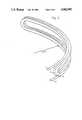
- FIG. 1is a three-dimensional illustration of a magnet system composed of four coils
- FIG. 2is a sectional view in the (x,y)-plane of FIG. 1;
- FIG. 3is a coil packet composed of a double pancake.
- the magnetic deflection systemis composed of four coils 1, 2, 3, 4 whose spatial arrangement can be seen when referring to the drawn (x,y,z)-coordinate system.
- the plane S E of the desired orbitlies in the (x,z)-plane in which the deflection path changes coordinates between the coils and parallel to the coils.
- the winding faces which have a curvature r r 0 adapted to the desired orbitare oriented perpendicular to the plane S E of the desired orbit.
- FIG. 2is a sectional view of the coil system in the (x,y)-plane.
- the area A 0 defined by the magnetic guide field and the deflection radius r 0is shown schematically and perpendicularly and intersects the plane S E of the desired orbit in the (x,z)-plane.
- coils 1, 2, 3, 4are arranged in such a manner that they do not intersect area A 0 .
- the winding faces of coils 1, 2, 3, 4may be parallel as shown here or also oriented at an angle with respect to area A 0 .
- FIG. 3shows a winding of the deflection system composed of a double pancake.
- Thisis a winding technique which is employed with preference in the manufacture of superconductive windings.
- a winding disc 5having a smaller radius of curvature r 1 r 0 is produced and supports during the winding process a second winding disc 6 having a radius of curvature r 2 >r 1 .
- the conductorcan always be wound with tension.
- several double pancakesmay be connected in series to form a winding packet.
- the conductor ends 7, 8, which are always disposed at the largest winding diameter,facilitate the establishment of connections between the double pancakes. With this type of coil, the conductor may also be processed under tension according to any other winding technique.
Landscapes
- Physics & Mathematics (AREA)
- Engineering & Computer Science (AREA)
- Electromagnetism (AREA)
- Spectroscopy & Molecular Physics (AREA)
- Power Engineering (AREA)
- General Engineering & Computer Science (AREA)
- High Energy & Nuclear Physics (AREA)
- Optics & Photonics (AREA)
- Plasma & Fusion (AREA)
- Particle Accelerators (AREA)
Abstract
Description
The invention relates to a magnetic deflection system for charged particles.
To guide particle beams on circular orbits, particularly in a synchrotron or mass spectrometer, it is necessary to have high magnetic field intensities which are generated by specially shaped bending magnets.
The deflection radius r0 is a function of the particle pulse p and of the magnetic field B. The following applies: ##EQU1## where q is the charge of the particle.
With a given particle pulse, small deflection radii r0 are produced with the largest possible magnetic fields. However, iron magnets have a technically realizable limit at 1.8 T. Higher fields can be realized with superconductive coils.
Details of the configuration and operation of such deflection systems are disclosed, for example, in the publication entitled "Entwurf einer Synchrotronstrahlungsquelle mit supraleitenden Ablenkmagneten fur die Mikrofertigung nach dem LIGA-Verfahren" [Design of a Synchrotron Radiation Source Equipped With Superconductive Deflection Magnets For Microproduction According To The LIGA Method], KfK 3976, September 1985, ISSN 0303-4003. This publication describes coil concepts for superconductive deflection magnets in which the magnetic guide field perpendicular to the plane of the desired orbit is generated by means of coils whose winding faces are disposed parallel to the plane of the desired orbit. The winding faces have two long sides parallel to the particle orbit and two short sides which cross the particle orbit. The required magnetic field is generated by electrical currents extending parallel to the particle orbit. The currents crossing the particle orbit produce excessive fields and field distortions which cause intensive interference in the orbit. This effect is greater the closer the winding packets are broght to the particle orbit. These interferences in the orbit are reduced in that the winding regions crossing over the particle orbit are brought away from the plane of the desired orbit. This results in complicated coil geometries and considerable manufacturing problems, particularly with the use of superconductors. Superconductive coils are produced according to the pre-tensioning principle in order to prevent conductor movement which is one of the causes of quench. In the prior art coils here under consideration, a conductor enclosing the winding face passes through an outer radius >r0 and an inner radius <r0, with r0 representing the deflection radius. When the coil is wound, no pretension can be applied in the region of the inner radius. Consequently, the pretensioning must be effected by clamping around the coil system. However, a synchrotron requires an arrangement in which the generated synchrotron light in the plane of the particle orbit is able to tangentially exit the magnet system. Consequently only those clamps must be employed which do not completely surround the coil system.
Such clamping elements are disclosed in German Patent No. 3,511,282. It describes a superconductive magnet system for particle accelerators of a synchrotron radiation source in which the winding faces of the coils are arranged parallel to the plane of the desired orbit and the windings cross the particle orbit.
It is an object of the invention to provide a magnet design for the above-mentioned magnetic deflection system which can be realized with a reduction of structural expenditures and facilitates the use of superconductive coils by its simple manufacturing technique.
The present invention provides magnetic deflection system for charged particles, which includes a coil arrangement for generating a magnetic guide field perpendicular to the plane of the desired orbit so as to guide the particles in the plane SE of the desired orbit on a deflection path on a deflection radius r0. The system has at least two coils which are arranged on top of one another on either side of an area A0 defined by the direction of the magnetic guide field and the deflection radius r0 so that the winding faces of the coils extend parallel to area A0, with at least two of the coils being disposed above the plane SE of the desired orbit and two below the plane SE of the desired orbit.
In a preferred embodiment, the coils are composed of at least one double pancake.
The advantages realized by the coil arrangement according to the invention are essentially that the coils can be manufactured according to the pre-tensioning principle in that the conductor is wound with tension according to conventional technology and at the ends of the magnets the winding packets are not brought across the particle orbit. Additionally, a sufficiently large gap is available to bring out the synchrotron radiation without having to relinquish the use of clamps unless such clamps would be superfluous in any case due to the winding technique employed.
The invention will be described below with reference to an embodiment and FIGS. 1 to 3.
FIG. 1 is a three-dimensional illustration of a magnet system composed of four coils;
FIG. 2 is a sectional view in the (x,y)-plane of FIG. 1; and
FIG. 3 is a coil packet composed of a double pancake.
According to FIG. 1, the magnetic deflection system is composed of fourcoils
FIG. 2 is a sectional view of the coil system in the (x,y)-plane. The area A0 defined by the magnetic guide field and the deflection radius r0 is shown schematically and perpendicularly and intersects the plane SE of the desired orbit in the (x,z)-plane. On both sides of area A0,coils coils
FIG. 3 shows a winding of the deflection system composed of a double pancake. This is a winding technique which is employed with preference in the manufacture of superconductive windings. Initially, awinding disc 5 having a smaller radius of curvature r1 r0 is produced and supports during the winding process a second windingdisc 6 having a radius of curvature r2 >r1. The conductor can always be wound with tension. As required, several double pancakes may be connected in series to form a winding packet. The conductor ends 7, 8, which are always disposed at the largest winding diameter, facilitate the establishment of connections between the double pancakes. With this type of coil, the conductor may also be processed under tension according to any other winding technique.
Claims (2)
1. Magnetic deflection system for charged particles, the system including a coil arrangement for generating a magnetic guide field perpendicular to the plane of the desired orbit so as to guide the particles in the plane SE of the desired orbit on a deflection path on a deflection radius r0, characterized in that at least two coils are arranged on top of one another on either side of an area A0 defined by the direction of the magnetic guide field and the deflection radius r0 so that the winding faces of the coils extend parallel to area A0, with at least two of the coils being disposed above the plane SE of the desired orbit and two below the plane SE of the desired orbit.
2. Magnetic deflection system according to claim 1, characterized in that the coils are composed of at least one double pancake.
Applications Claiming Priority (2)
| Application Number | Priority Date | Filing Date | Title |
|---|---|---|---|
| DE19873705294DE3705294A1 (en) | 1987-02-19 | 1987-02-19 | MAGNETIC DEFLECTION SYSTEM FOR CHARGED PARTICLES |
| DE3705294 | 1987-02-19 |
Publications (1)
| Publication Number | Publication Date |
|---|---|
| US4902993Atrue US4902993A (en) | 1990-02-20 |
Family
ID=6321329
Family Applications (1)
| Application Number | Title | Priority Date | Filing Date |
|---|---|---|---|
| US07/290,259Expired - Fee RelatedUS4902993A (en) | 1987-02-19 | 1988-02-18 | Magnetic deflection system for charged particles |
Country Status (5)
| Country | Link |
|---|---|
| US (1) | US4902993A (en) |
| EP (1) | EP0348403B1 (en) |
| JP (1) | JPH02502684A (en) |
| DE (1) | DE3705294A1 (en) |
| WO (1) | WO1988006394A1 (en) |
Cited By (33)
| Publication number | Priority date | Publication date | Assignee | Title |
|---|---|---|---|---|
| US5117212A (en)* | 1989-01-12 | 1992-05-26 | Mitsubishi Denki Kabushiki Kaisha | Electromagnet for charged-particle apparatus |
| US5278533A (en)* | 1990-08-31 | 1994-01-11 | Mitsubishi Denki Kabushiki Kaisha | Coil for use in charged particle deflecting electromagnet and method of manufacturing the same |
| US5463291A (en)* | 1993-12-23 | 1995-10-31 | Carroll; Lewis | Cyclotron and associated magnet coil and coil fabricating process |
| WO1999066535A3 (en)* | 1998-06-19 | 2000-04-27 | Superion Ltd | Apparatus and method relating to charged particles |
| US20080093567A1 (en)* | 2005-11-18 | 2008-04-24 | Kenneth Gall | Charged particle radiation therapy |
| US20090096179A1 (en)* | 2007-10-11 | 2009-04-16 | Still River Systems Inc. | Applying a particle beam to a patient |
| US20090140672A1 (en)* | 2007-11-30 | 2009-06-04 | Kenneth Gall | Interrupted Particle Source |
| US20090140671A1 (en)* | 2007-11-30 | 2009-06-04 | O'neal Iii Charles D | Matching a resonant frequency of a resonant cavity to a frequency of an input voltage |
| DE102008009494A1 (en)* | 2008-02-15 | 2009-08-27 | Fachhochschule Dortmund | Device for measuring concentration and/or size distribution of soot particles in diesel exhaust gas of diesel vehicle in workshops, has magnets exhibiting magnetic field to deflect particles to electrodes dependent on size |
| US20100045213A1 (en)* | 2004-07-21 | 2010-02-25 | Still River Systems, Inc. | Programmable Radio Frequency Waveform Generator for a Synchrocyclotron |
| GB2478265A (en)* | 2008-09-03 | 2011-09-07 | Superion Ltd | Apparatus and method relating to the focusing of charged particles |
| US8791656B1 (en) | 2013-05-31 | 2014-07-29 | Mevion Medical Systems, Inc. | Active return system |
| US8927950B2 (en) | 2012-09-28 | 2015-01-06 | Mevion Medical Systems, Inc. | Focusing a particle beam |
| US9155186B2 (en) | 2012-09-28 | 2015-10-06 | Mevion Medical Systems, Inc. | Focusing a particle beam using magnetic field flutter |
| US9185789B2 (en) | 2012-09-28 | 2015-11-10 | Mevion Medical Systems, Inc. | Magnetic shims to alter magnetic fields |
| US9301384B2 (en) | 2012-09-28 | 2016-03-29 | Mevion Medical Systems, Inc. | Adjusting energy of a particle beam |
| US9545528B2 (en) | 2012-09-28 | 2017-01-17 | Mevion Medical Systems, Inc. | Controlling particle therapy |
| US9622335B2 (en) | 2012-09-28 | 2017-04-11 | Mevion Medical Systems, Inc. | Magnetic field regenerator |
| US9661736B2 (en) | 2014-02-20 | 2017-05-23 | Mevion Medical Systems, Inc. | Scanning system for a particle therapy system |
| US9681531B2 (en) | 2012-09-28 | 2017-06-13 | Mevion Medical Systems, Inc. | Control system for a particle accelerator |
| US9723705B2 (en) | 2012-09-28 | 2017-08-01 | Mevion Medical Systems, Inc. | Controlling intensity of a particle beam |
| US9730308B2 (en) | 2013-06-12 | 2017-08-08 | Mevion Medical Systems, Inc. | Particle accelerator that produces charged particles having variable energies |
| US9950194B2 (en) | 2014-09-09 | 2018-04-24 | Mevion Medical Systems, Inc. | Patient positioning system |
| US9962560B2 (en) | 2013-12-20 | 2018-05-08 | Mevion Medical Systems, Inc. | Collimator and energy degrader |
| US10254739B2 (en) | 2012-09-28 | 2019-04-09 | Mevion Medical Systems, Inc. | Coil positioning system |
| US10258810B2 (en) | 2013-09-27 | 2019-04-16 | Mevion Medical Systems, Inc. | Particle beam scanning |
| US10646728B2 (en) | 2015-11-10 | 2020-05-12 | Mevion Medical Systems, Inc. | Adaptive aperture |
| US10653892B2 (en) | 2017-06-30 | 2020-05-19 | Mevion Medical Systems, Inc. | Configurable collimator controlled using linear motors |
| US10675487B2 (en) | 2013-12-20 | 2020-06-09 | Mevion Medical Systems, Inc. | Energy degrader enabling high-speed energy switching |
| US10925147B2 (en) | 2016-07-08 | 2021-02-16 | Mevion Medical Systems, Inc. | Treatment planning |
| US10984935B2 (en)* | 2017-05-02 | 2021-04-20 | Hefei Institutes Of Physical Science, Chinese Academy Of Sciences | Superconducting dipole magnet structure for particle deflection |
| US11103730B2 (en) | 2017-02-23 | 2021-08-31 | Mevion Medical Systems, Inc. | Automated treatment in particle therapy |
| US11291861B2 (en) | 2019-03-08 | 2022-04-05 | Mevion Medical Systems, Inc. | Delivery of radiation by column and generating a treatment plan therefor |
Families Citing this family (1)
| Publication number | Priority date | Publication date | Assignee | Title |
|---|---|---|---|---|
| CN1088246C (en)† | 1994-10-13 | 2002-07-24 | 美国超导体公司 | Variable profile superconducting magnetic coil |
Citations (4)
| Publication number | Priority date | Publication date | Assignee | Title |
|---|---|---|---|---|
| DE2318507A1 (en)* | 1973-04-12 | 1974-10-31 | Siemens Ag | SUPRA LINE MAGNETIC COIL WITH A TWO- OR MULTIPOLE WINDING |
| FR2341922A1 (en)* | 1976-02-17 | 1977-09-16 | Cgr Mev | IMPROVEMENT TO A TARGET SCANNING DEVICE BY A CHARGED PARTICLE BEAM |
| EP0208163A1 (en)* | 1985-06-24 | 1987-01-14 | Siemens Aktiengesellschaft | Magnetic-field device for an apparatus for accelerating and/or storing electrically charged particles |
| US4769623A (en)* | 1987-01-28 | 1988-09-06 | Siemens Aktiengesellschaft | Magnetic device with curved superconducting coil windings |
Family Cites Families (2)
| Publication number | Priority date | Publication date | Assignee | Title |
|---|---|---|---|---|
| JPS5572019A (en)* | 1978-11-25 | 1980-05-30 | Toshiba Corp | Preparation of saddle type multi-wound coil |
| DE3505281A1 (en)* | 1985-02-15 | 1986-08-21 | Siemens AG, 1000 Berlin und 8000 München | MAGNETIC FIELD GENERATING DEVICE |
- 1987
- 1987-02-19DEDE19873705294patent/DE3705294A1/enactiveGranted
- 1988
- 1988-02-18WOPCT/DE1988/000079patent/WO1988006394A1/enactiveIP Right Grant
- 1988-02-18JPJP88501628Apatent/JPH02502684A/enactivePending
- 1988-02-18USUS07/290,259patent/US4902993A/ennot_activeExpired - Fee Related
- 1988-02-18EPEP88901560Apatent/EP0348403B1/ennot_activeExpired - Lifetime
Patent Citations (5)
| Publication number | Priority date | Publication date | Assignee | Title |
|---|---|---|---|---|
| DE2318507A1 (en)* | 1973-04-12 | 1974-10-31 | Siemens Ag | SUPRA LINE MAGNETIC COIL WITH A TWO- OR MULTIPOLE WINDING |
| FR2341922A1 (en)* | 1976-02-17 | 1977-09-16 | Cgr Mev | IMPROVEMENT TO A TARGET SCANNING DEVICE BY A CHARGED PARTICLE BEAM |
| EP0208163A1 (en)* | 1985-06-24 | 1987-01-14 | Siemens Aktiengesellschaft | Magnetic-field device for an apparatus for accelerating and/or storing electrically charged particles |
| US4680565A (en)* | 1985-06-24 | 1987-07-14 | Siemens Aktiengesellschaft | Magnetic field device for a system for the acceleration and/or storage of electrically charged particles |
| US4769623A (en)* | 1987-01-28 | 1988-09-06 | Siemens Aktiengesellschaft | Magnetic device with curved superconducting coil windings |
Non-Patent Citations (6)
| Title |
|---|
| J. E. Draper: "Beam Sterring with Quadrupole and with Rectangular Box Magnets", Oct. 1966, pp. 1390-1394. |
| J. E. Draper: Beam Sterring with Quadrupole and with Rectangular Box Magnets , Oct. 1966, pp. 1390 1394.* |
| T. E. Wood: "High Magnetic Field Techniques for Neutron and X-Ray Scattering", Sep. 1984, pp. 685-690. |
| T. E. Wood: High Magnetic Field Techniques for Neutron and X Ray Scattering , Sep. 1984, pp. 685 690.* |
| W. Heinz: "Research Work on Superconducting Magnet Systems in Germany", Mar. 1975, pp. 148-153. |
| W. Heinz: Research Work on Superconducting Magnet Systems in Germany , Mar. 1975, pp. 148 153.* |
Cited By (67)
| Publication number | Priority date | Publication date | Assignee | Title |
|---|---|---|---|---|
| US5117212A (en)* | 1989-01-12 | 1992-05-26 | Mitsubishi Denki Kabushiki Kaisha | Electromagnet for charged-particle apparatus |
| US5278533A (en)* | 1990-08-31 | 1994-01-11 | Mitsubishi Denki Kabushiki Kaisha | Coil for use in charged particle deflecting electromagnet and method of manufacturing the same |
| US5461773A (en)* | 1990-08-31 | 1995-10-31 | Mitsubishi Denki Kabushiki Kaisha | Method of manufacturing coils for use in charged particle deflecting electromagnet |
| US5463291A (en)* | 1993-12-23 | 1995-10-31 | Carroll; Lewis | Cyclotron and associated magnet coil and coil fabricating process |
| WO1999066535A3 (en)* | 1998-06-19 | 2000-04-27 | Superion Ltd | Apparatus and method relating to charged particles |
| USRE48047E1 (en) | 2004-07-21 | 2020-06-09 | Mevion Medical Systems, Inc. | Programmable radio frequency waveform generator for a synchrocyclotron |
| US8952634B2 (en) | 2004-07-21 | 2015-02-10 | Mevion Medical Systems, Inc. | Programmable radio frequency waveform generator for a synchrocyclotron |
| US20100045213A1 (en)* | 2004-07-21 | 2010-02-25 | Still River Systems, Inc. | Programmable Radio Frequency Waveform Generator for a Synchrocyclotron |
| US10279199B2 (en) | 2005-11-18 | 2019-05-07 | Mevion Medical Systems, Inc. | Inner gantry |
| US20090200483A1 (en)* | 2005-11-18 | 2009-08-13 | Still River Systems Incorporated | Inner Gantry |
| US8907311B2 (en) | 2005-11-18 | 2014-12-09 | Mevion Medical Systems, Inc. | Charged particle radiation therapy |
| US9925395B2 (en) | 2005-11-18 | 2018-03-27 | Mevion Medical Systems, Inc. | Inner gantry |
| US7728311B2 (en) | 2005-11-18 | 2010-06-01 | Still River Systems Incorporated | Charged particle radiation therapy |
| US20100230617A1 (en)* | 2005-11-18 | 2010-09-16 | Still River Systems Incorporated, a Delaware Corporation | Charged particle radiation therapy |
| US9452301B2 (en) | 2005-11-18 | 2016-09-27 | Mevion Medical Systems, Inc. | Inner gantry |
| US20080093567A1 (en)* | 2005-11-18 | 2008-04-24 | Kenneth Gall | Charged particle radiation therapy |
| US8344340B2 (en) | 2005-11-18 | 2013-01-01 | Mevion Medical Systems, Inc. | Inner gantry |
| US10722735B2 (en) | 2005-11-18 | 2020-07-28 | Mevion Medical Systems, Inc. | Inner gantry |
| US8916843B2 (en) | 2005-11-18 | 2014-12-23 | Mevion Medical Systems, Inc. | Inner gantry |
| US8003964B2 (en) | 2007-10-11 | 2011-08-23 | Still River Systems Incorporated | Applying a particle beam to a patient |
| US8941083B2 (en) | 2007-10-11 | 2015-01-27 | Mevion Medical Systems, Inc. | Applying a particle beam to a patient |
| US20090096179A1 (en)* | 2007-10-11 | 2009-04-16 | Still River Systems Inc. | Applying a particle beam to a patient |
| USRE48317E1 (en) | 2007-11-30 | 2020-11-17 | Mevion Medical Systems, Inc. | Interrupted particle source |
| US8581523B2 (en) | 2007-11-30 | 2013-11-12 | Mevion Medical Systems, Inc. | Interrupted particle source |
| US8933650B2 (en) | 2007-11-30 | 2015-01-13 | Mevion Medical Systems, Inc. | Matching a resonant frequency of a resonant cavity to a frequency of an input voltage |
| US8970137B2 (en) | 2007-11-30 | 2015-03-03 | Mevion Medical Systems, Inc. | Interrupted particle source |
| US20090140671A1 (en)* | 2007-11-30 | 2009-06-04 | O'neal Iii Charles D | Matching a resonant frequency of a resonant cavity to a frequency of an input voltage |
| US20090140672A1 (en)* | 2007-11-30 | 2009-06-04 | Kenneth Gall | Interrupted Particle Source |
| DE102008009494A1 (en)* | 2008-02-15 | 2009-08-27 | Fachhochschule Dortmund | Device for measuring concentration and/or size distribution of soot particles in diesel exhaust gas of diesel vehicle in workshops, has magnets exhibiting magnetic field to deflect particles to electrodes dependent on size |
| GB2478265B (en)* | 2008-09-03 | 2013-06-19 | Superion Ltd | Apparatus and method relating to the focusing of charged particles |
| GB2478265A (en)* | 2008-09-03 | 2011-09-07 | Superion Ltd | Apparatus and method relating to the focusing of charged particles |
| US9622335B2 (en) | 2012-09-28 | 2017-04-11 | Mevion Medical Systems, Inc. | Magnetic field regenerator |
| US9185789B2 (en) | 2012-09-28 | 2015-11-10 | Mevion Medical Systems, Inc. | Magnetic shims to alter magnetic fields |
| US8927950B2 (en) | 2012-09-28 | 2015-01-06 | Mevion Medical Systems, Inc. | Focusing a particle beam |
| US9681531B2 (en) | 2012-09-28 | 2017-06-13 | Mevion Medical Systems, Inc. | Control system for a particle accelerator |
| US9706636B2 (en) | 2012-09-28 | 2017-07-11 | Mevion Medical Systems, Inc. | Adjusting energy of a particle beam |
| US9723705B2 (en) | 2012-09-28 | 2017-08-01 | Mevion Medical Systems, Inc. | Controlling intensity of a particle beam |
| US9301384B2 (en) | 2012-09-28 | 2016-03-29 | Mevion Medical Systems, Inc. | Adjusting energy of a particle beam |
| US9155186B2 (en) | 2012-09-28 | 2015-10-06 | Mevion Medical Systems, Inc. | Focusing a particle beam using magnetic field flutter |
| US9545528B2 (en) | 2012-09-28 | 2017-01-17 | Mevion Medical Systems, Inc. | Controlling particle therapy |
| US10155124B2 (en) | 2012-09-28 | 2018-12-18 | Mevion Medical Systems, Inc. | Controlling particle therapy |
| US10254739B2 (en) | 2012-09-28 | 2019-04-09 | Mevion Medical Systems, Inc. | Coil positioning system |
| US10368429B2 (en) | 2012-09-28 | 2019-07-30 | Mevion Medical Systems, Inc. | Magnetic field regenerator |
| US8791656B1 (en) | 2013-05-31 | 2014-07-29 | Mevion Medical Systems, Inc. | Active return system |
| US9730308B2 (en) | 2013-06-12 | 2017-08-08 | Mevion Medical Systems, Inc. | Particle accelerator that produces charged particles having variable energies |
| US10258810B2 (en) | 2013-09-27 | 2019-04-16 | Mevion Medical Systems, Inc. | Particle beam scanning |
| US10456591B2 (en) | 2013-09-27 | 2019-10-29 | Mevion Medical Systems, Inc. | Particle beam scanning |
| US9962560B2 (en) | 2013-12-20 | 2018-05-08 | Mevion Medical Systems, Inc. | Collimator and energy degrader |
| US10675487B2 (en) | 2013-12-20 | 2020-06-09 | Mevion Medical Systems, Inc. | Energy degrader enabling high-speed energy switching |
| US10434331B2 (en) | 2014-02-20 | 2019-10-08 | Mevion Medical Systems, Inc. | Scanning system |
| US11717700B2 (en) | 2014-02-20 | 2023-08-08 | Mevion Medical Systems, Inc. | Scanning system |
| US9661736B2 (en) | 2014-02-20 | 2017-05-23 | Mevion Medical Systems, Inc. | Scanning system for a particle therapy system |
| US9950194B2 (en) | 2014-09-09 | 2018-04-24 | Mevion Medical Systems, Inc. | Patient positioning system |
| US10646728B2 (en) | 2015-11-10 | 2020-05-12 | Mevion Medical Systems, Inc. | Adaptive aperture |
| US11786754B2 (en) | 2015-11-10 | 2023-10-17 | Mevion Medical Systems, Inc. | Adaptive aperture |
| US10786689B2 (en) | 2015-11-10 | 2020-09-29 | Mevion Medical Systems, Inc. | Adaptive aperture |
| US11213697B2 (en) | 2015-11-10 | 2022-01-04 | Mevion Medical Systems, Inc. | Adaptive aperture |
| US10925147B2 (en) | 2016-07-08 | 2021-02-16 | Mevion Medical Systems, Inc. | Treatment planning |
| US12150235B2 (en) | 2016-07-08 | 2024-11-19 | Mevion Medical Systems, Inc. | Treatment planning |
| US11103730B2 (en) | 2017-02-23 | 2021-08-31 | Mevion Medical Systems, Inc. | Automated treatment in particle therapy |
| US10984935B2 (en)* | 2017-05-02 | 2021-04-20 | Hefei Institutes Of Physical Science, Chinese Academy Of Sciences | Superconducting dipole magnet structure for particle deflection |
| US10653892B2 (en) | 2017-06-30 | 2020-05-19 | Mevion Medical Systems, Inc. | Configurable collimator controlled using linear motors |
| US11311746B2 (en) | 2019-03-08 | 2022-04-26 | Mevion Medical Systems, Inc. | Collimator and energy degrader for a particle therapy system |
| US11717703B2 (en) | 2019-03-08 | 2023-08-08 | Mevion Medical Systems, Inc. | Delivery of radiation by column and generating a treatment plan therefor |
| US11291861B2 (en) | 2019-03-08 | 2022-04-05 | Mevion Medical Systems, Inc. | Delivery of radiation by column and generating a treatment plan therefor |
| US12161885B2 (en) | 2019-03-08 | 2024-12-10 | Mevion Medical Systems, Inc. | Delivery of radiation by column and generating a treatment plan therefor |
| US12168147B2 (en) | 2019-03-08 | 2024-12-17 | Mevion Medical Systems, Inc. | Collimator and energy degrader for a particle therapy system |
Also Published As
| Publication number | Publication date |
|---|---|
| DE3705294A1 (en) | 1988-09-01 |
| JPH02502684A (en) | 1990-08-23 |
| DE3705294C2 (en) | 1993-06-09 |
| EP0348403A1 (en) | 1990-01-03 |
| EP0348403B1 (en) | 1994-03-30 |
| WO1988006394A1 (en) | 1988-08-25 |
Similar Documents
| Publication | Publication Date | Title |
|---|---|---|
| US4902993A (en) | Magnetic deflection system for charged particles | |
| US4740758A (en) | Apparatus for generating a magnetic field in a volume having bodies influencing the field pattern | |
| US4425506A (en) | Stepped gap achromatic bending magnet | |
| EP0582193B1 (en) | Synchrotron radiation light-source apparatus and method of manufacturing same | |
| US4710722A (en) | Apparatus generating a magnetic field for a particle accelerator | |
| JPH06501334A (en) | synchrotron radiation source | |
| US4359706A (en) | Magnet pole pieces and pole piece extensions and shields | |
| JPS63188908A (en) | Magnet device with curved coil winding | |
| GB1523458A (en) | Wien filter | |
| JPH10233299A (en) | Charged particle beam expander | |
| US4191887A (en) | Magnetic beam deflection system free of chromatic and geometric aberrations of second order | |
| EP0396919A3 (en) | Plasma reactor and method for semiconductor processing | |
| US5049847A (en) | Deflection yoke with auxiliary coils for stray line radiation suppression | |
| EP0041753B1 (en) | Deflection system for charged-particle beam | |
| CN111673259A (en) | Split type electron beam deflection coil and electron beam equipment | |
| US4455489A (en) | Quadrupole singlet focusing for achromatic parallel-to-parallel devices | |
| EP0700236B1 (en) | Injection apparatus both for positive and negative ions | |
| US3723730A (en) | Multiple ion source array | |
| US3708772A (en) | Magnetic lens arrangement | |
| US3357096A (en) | Process for the production of a tube for the bundled guidance of an electron beam | |
| JP2949654B2 (en) | Electron storage ring | |
| JPH02226699A (en) | Deflecting electromagnet for charged particle accelerator | |
| JPH03220500A (en) | Coil for charged particle bending electromagnet | |
| JPS6435899A (en) | Saddle type dipole deflecting magnet for accumulating charged particle | |
| JPS6420489A (en) | Tours type nuclear fusion equipment |
Legal Events
| Date | Code | Title | Description |
|---|---|---|---|
| AS | Assignment | Owner name:KERNFORSCHUNGSZENTRUM KARLSRUHE GMBH, GERMANY Free format text:ASSIGNMENT OF ASSIGNORS INTEREST.;ASSIGNOR:KREVET, BERTHOLD;REEL/FRAME:005028/0004 Effective date:19881111 | |
| FPAY | Fee payment | Year of fee payment:4 | |
| REMI | Maintenance fee reminder mailed | ||
| LAPS | Lapse for failure to pay maintenance fees | ||
| FP | Lapsed due to failure to pay maintenance fee | Effective date:19980225 | |
| STCH | Information on status: patent discontinuation | Free format text:PATENT EXPIRED DUE TO NONPAYMENT OF MAINTENANCE FEES UNDER 37 CFR 1.362 |