US4902083A - Low vibration resonant scanning unit for miniature optical display apparatus - Google Patents
Low vibration resonant scanning unit for miniature optical display apparatusDownload PDFInfo
- Publication number
- US4902083A US4902083AUS07/200,645US20064588AUS4902083AUS 4902083 AUS4902083 AUS 4902083AUS 20064588 AUS20064588 AUS 20064588AUS 4902083 AUS4902083 AUS 4902083A
- Authority
- US
- United States
- Prior art keywords
- mirror
- base
- spring
- counterbalance mass
- coil
- Prior art date
- Legal status (The legal status is an assumption and is not a legal conclusion. Google has not performed a legal analysis and makes no representation as to the accuracy of the status listed.)
- Expired - Lifetime
Links
Images


Classifications
- G—PHYSICS
- G02—OPTICS
- G02B—OPTICAL ELEMENTS, SYSTEMS OR APPARATUS
- G02B26/00—Optical devices or arrangements for the control of light using movable or deformable optical elements
- G02B26/08—Optical devices or arrangements for the control of light using movable or deformable optical elements for controlling the direction of light
- G02B26/10—Scanning systems
- G—PHYSICS
- G06—COMPUTING OR CALCULATING; COUNTING
- G06K—GRAPHICAL DATA READING; PRESENTATION OF DATA; RECORD CARRIERS; HANDLING RECORD CARRIERS
- G06K7/00—Methods or arrangements for sensing record carriers, e.g. for reading patterns
- G06K7/10—Methods or arrangements for sensing record carriers, e.g. for reading patterns by electromagnetic radiation, e.g. optical sensing; by corpuscular radiation
- G06K7/10544—Methods or arrangements for sensing record carriers, e.g. for reading patterns by electromagnetic radiation, e.g. optical sensing; by corpuscular radiation by scanning of the records by radiation in the optical part of the electromagnetic spectrum
- G06K7/10554—Moving beam scanning
- G06K7/10594—Beam path
- G06K7/10603—Basic scanning using moving elements
- G06K7/10633—Basic scanning using moving elements by oscillation
- G06K7/10643—Activating means
- G06K7/10653—Activating means using flexible or piezoelectric means
Definitions
- Another display deviceis an electromechanical scanning system in which a line of light-emitting devices is modulated with the information to be displayed. The illuminated line is converted into a raster by means of an oscillating mirror thereby generating a virtual raster image.
- These latter deviceshave the advantage that a full "page" display can be created from a much smaller number of light-emitting devices than is necessary to generate a normal full page real image.
- an enlarged, virtual image of the illuminated devicesis reflected from a mirror as the mirror is being physically pivoted about a fixed axis by means of an electromagnetic motor.
- an electromagnetic motoroscillates the mirror mass at the resonant frequency of the spring/mirror system. In this manner, only a small amount of power is needed to produce a relatively large oscillation.
- a conventional resonant oscillatoris shown in U.S. Pat. No. 4,632,501 in which the mirror is attached to the base by a thin sheet of spring material.
- the mirror supportconsists of a "tuning-fork” configuration with the mirror mounted on one arm and a counterbalance mass mounted on the other arm.
- the driving motorcomprises a magnet and coil structure which drives one or more of the the arms so that the arms move in opposite directions.
- the mirroris mounted to the base of the display device by crossed flexure springs.
- a counterbalance massis also connected to the base of the video display device by a spring. The stiffness of both the mirror flexures and the counterbalance mass spring are selected so that the mirror and counterbalance mass have substantially the same resonant frequency.
- a voice-coil electromagnetic motoris used to dive the mirror and the counterbalance mass.
- the motorcomprises a permanent magnet portion and associated magnetic return path mounted on one arm of the tuning fork configuration and a coil mounted on the other arm.
- a properly controlled currentis applied to the coil, the permanent magnet is alternately attracted and repulsed from the coil.
- a driving forceis applied to both the mirror and the counterbalance mass causing each to oscillate at the frequency of the driving force.
- the geometry of the electromagnetic motoris selected so that the drive forces applied to the mirror and counterbalance mass are substantially equal to the air resistance forces acting on the mirror and counterbalance mass, with the result that little or no net force is applied to the base due to drive forces.
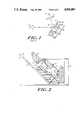
- FIG. 1is a schematic view of a typical prior art resonant electromechanical scanner.
- FIG. 3Ais a schematic diagram of a miniature display using a scanning mirror which is pivoted near the mirror center.
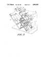
- FIG. 5is a perspective view of a preferred embodiment of a resonant scanner utilizing a drive motor with improved efficiency.
- FIG. 12is a perspective view of a miniature optical display device utilizing an illustrative embodiment of the inventive scanner unit.
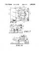
- FIG. 2shows a partial cross-sectional view of the mirror assembly of the present invention.
- mirror 30is part of a balanced assembly with two arms.
- One armcomprises mirror 30, mirror support 36 and driving coil 46.
- the other armconsists of weight 40 and permanent magnet 44.
- the mirror armis attached to base mounting 21 by means of two flexure springs 32 and 34.
- Springs 32 and 34are both flat springs which extend into the page. As will be discussed hereinafter, two springs are used in a crossed arrangement to constrain rotation of the mirror assembly to a single axis.
- Weight 40is attached to the one end of spring 42 by means of fastener 43.
- Spring 42is also a flat spring extending into the page.
- the other end of spring 42is attached to base 21 by means of fastener 45.
- Weight 40thus effectively pivots around an intermediate point located on spring 42 between attachment points 43 and 45.
- Mirror 30is actuated by providing a periodic current via leads 50 and 55 (shown in FIG. 4) to coil 46, causing mirror 30 and weight 40 to oscillate. The oscillation of mirror 30, in turn, creates a raster image from linear array 15.
Landscapes
- Physics & Mathematics (AREA)
- General Physics & Mathematics (AREA)
- Engineering & Computer Science (AREA)
- Electromagnetism (AREA)
- Toxicology (AREA)
- General Health & Medical Sciences (AREA)
- Health & Medical Sciences (AREA)
- Optics & Photonics (AREA)
- Artificial Intelligence (AREA)
- Computer Vision & Pattern Recognition (AREA)
- Theoretical Computer Science (AREA)
- Mechanical Optical Scanning Systems (AREA)
- Control Of Indicators Other Than Cathode Ray Tubes (AREA)
Abstract
Description
Claims (26)
Priority Applications (10)
| Application Number | Priority Date | Filing Date | Title |
|---|---|---|---|
| US07/200,645US4902083A (en) | 1988-05-31 | 1988-05-31 | Low vibration resonant scanning unit for miniature optical display apparatus |
| AU29986/89AAU618783B2 (en) | 1988-05-31 | 1989-02-16 | Low vibration resonant scanning unit for miniature optical display apparatus |
| ES89301850TES2082770T3 (en) | 1988-05-31 | 1989-02-24 | LOW VIBRATION RESONANT SCANNING UNIT FOR A MINIATURE OPTICAL REPRESENTATION DEVICE. |
| EP89301850AEP0344882B1 (en) | 1988-05-31 | 1989-02-24 | Low vibration resonant scanning unit for miniature optical display apparatus |
| DE68925236TDE68925236T2 (en) | 1988-05-31 | 1989-02-24 | Low vibration resonance scanner for a miniature optical display device |
| AT89301850TATE132277T1 (en) | 1988-05-31 | 1989-02-24 | LOW VIBRATION RESONANCE SCANNING SYSTEM FOR A MINIATURE OPTICAL DISPLAY DEVICE |
| JP1122702AJP2784208B2 (en) | 1988-05-31 | 1989-05-16 | Low-vibration resonant scanner for small optical display devices |
| IL90393AIL90393A0 (en) | 1988-05-31 | 1989-05-23 | Low vibration resonant scanning unit for miniature optical display apparatus |
| CA000601130ACA1331232C (en) | 1988-05-31 | 1989-05-30 | Low vibration resonant scanning unit for miniature optical display apparatus |
| US07/434,351US5009473A (en) | 1988-05-31 | 1989-11-13 | Low vibration resonant scanning unit for miniature optical display apparatus |
Applications Claiming Priority (1)
| Application Number | Priority Date | Filing Date | Title |
|---|---|---|---|
| US07/200,645US4902083A (en) | 1988-05-31 | 1988-05-31 | Low vibration resonant scanning unit for miniature optical display apparatus |
Related Child Applications (2)
| Application Number | Title | Priority Date | Filing Date |
|---|---|---|---|
| US07/200,692Continuation-In-PartUS5003300A (en) | 1987-07-27 | 1988-05-31 | Head mounted display for miniature video display system |
| US07/434,351Continuation-In-PartUS5009473A (en) | 1988-05-31 | 1989-11-13 | Low vibration resonant scanning unit for miniature optical display apparatus |
Publications (1)
| Publication Number | Publication Date |
|---|---|
| US4902083Atrue US4902083A (en) | 1990-02-20 |
Family
ID=22742578
Family Applications (1)
| Application Number | Title | Priority Date | Filing Date |
|---|---|---|---|
| US07/200,645Expired - LifetimeUS4902083A (en) | 1988-05-31 | 1988-05-31 | Low vibration resonant scanning unit for miniature optical display apparatus |
Country Status (9)
| Country | Link |
|---|---|
| US (1) | US4902083A (en) |
| EP (1) | EP0344882B1 (en) |
| JP (1) | JP2784208B2 (en) |
| AT (1) | ATE132277T1 (en) |
| AU (1) | AU618783B2 (en) |
| CA (1) | CA1331232C (en) |
| DE (1) | DE68925236T2 (en) |
| ES (1) | ES2082770T3 (en) |
| IL (1) | IL90393A0 (en) |
Cited By (145)
| Publication number | Priority date | Publication date | Assignee | Title |
|---|---|---|---|---|
| US5009473A (en)* | 1988-05-31 | 1991-04-23 | Reflection Technology, Inc. | Low vibration resonant scanning unit for miniature optical display apparatus |
| US5097355A (en)* | 1988-07-28 | 1992-03-17 | Benjamin Eden | Scanning device |
| US5099110A (en)* | 1989-10-30 | 1992-03-24 | Symbol Technologies, Inc. | Power saving scanning arrangement |
| US5115120A (en)* | 1990-06-26 | 1992-05-19 | Photographic Sciences Corporation | Scan modules for bar code readers and in which scan elements are flexurally supported |
| US5155615A (en)* | 1988-04-15 | 1992-10-13 | Sharp Kabushiki Kaisha | Miniature display device for use in a miniature electronic apparatus |
| US5168149A (en)* | 1989-10-30 | 1992-12-01 | Symbol Technologies, Inc. | Scan pattern generators for bar code symbol readers |
| US5170277A (en)* | 1988-05-11 | 1992-12-08 | Symbol Technologies, Inc. | Piezoelectric beam deflector |
| US5206492A (en)* | 1989-10-30 | 1993-04-27 | Symbol Technologies, Inc. | Bar code symbol scanner with reduced power usage to effect reading |
| US5210636A (en)* | 1991-07-19 | 1993-05-11 | Baer Stephen C | Rotational oscillatory optical scanning device |
| US5214279A (en)* | 1990-07-26 | 1993-05-25 | Fuji Photo Film Co., Ltd. | Scanning microscope and tuning fork scanning mechanism for varying the width over which a sample is scanned |
| US5245463A (en)* | 1990-08-07 | 1993-09-14 | Omron Corporation | Optical scanner |
| WO1993021673A1 (en)* | 1992-04-21 | 1993-10-28 | Bandgap Technology Corporation | Vertical-cavity surface-emitting laser abray display system |
| US5262627A (en)* | 1989-10-30 | 1993-11-16 | Symbol Technologies, Inc. | Scanning arrangement and method |
| US5280378A (en)* | 1990-10-19 | 1994-01-18 | I.L. Med, Inc. | Cyclically scanned medical laser |
| US5280377A (en)* | 1991-06-28 | 1994-01-18 | Eastman Kodak Company | Beam scanning galvanometer with spring supported mirror |
| US5280165A (en)* | 1989-10-30 | 1994-01-18 | Symbol Technolgoies, Inc. | Scan pattern generators for bar code symbol readers |
| US5283682A (en)* | 1992-10-06 | 1994-02-01 | Ball Corporation | Reactionless scanning and positioning system |
| US5329103A (en)* | 1991-10-30 | 1994-07-12 | Spectra-Physics | Laser beam scanner with low cost ditherer mechanism |
| US5359675A (en)* | 1990-07-26 | 1994-10-25 | Ronald Siwoff | Video spectacles |
| US5367151A (en)* | 1989-10-30 | 1994-11-22 | Symbol Technologies, Inc. | Slim scan module with interchangeable scan element |
| US5373148A (en)* | 1989-10-30 | 1994-12-13 | Symbol Technologies, Inc. | Optical scanners with scan motion damping and orientation of astigmantic laser generator to optimize reading of two-dimensionally coded indicia |
| US5374817A (en)* | 1988-05-11 | 1994-12-20 | Symbol Technologies, Inc. | Pre-objective scanner with flexible optical support |
| US5410140A (en)* | 1988-05-11 | 1995-04-25 | Symbol Technologies, Inc. | Mirrorless ring mounted miniature optical scanner |
| US5412198A (en)* | 1989-10-30 | 1995-05-02 | Symbol Technologies, Inc. | High-speed scanning arrangement with high-frequency, low-stress scan element |
| US5479000A (en)* | 1989-10-30 | 1995-12-26 | Symbol Technologies, Inc. | Compact scanning module for reading bar codes |
| US5481099A (en)* | 1989-10-30 | 1996-01-02 | Symbol Technologies, Inc. | Scanning arrangement for the implementation of omni-directional scanning patterns over indicia |
| US5514861A (en)* | 1988-05-11 | 1996-05-07 | Symbol Technologies, Inc. | Computer and/or scanner system mounted on a glove |
| US5526022A (en) | 1993-01-06 | 1996-06-11 | Virtual I/O, Inc. | Sourceless orientation sensor |
| US5543610A (en)* | 1989-10-30 | 1996-08-06 | Symbol Technologies, Inc. | Compact bar code scanning arrangement |
| US5552592A (en)* | 1989-10-30 | 1996-09-03 | Symbol Technologies, Inc. | Slim scan module with dual detectors |
| US5583331A (en)* | 1989-10-30 | 1996-12-10 | Symbol Technologies, Inc. | Arrangement for compensating for scan line curvature |
| US5614706A (en)* | 1992-05-15 | 1997-03-25 | Symbol Technologies, Inc. | Bar code scanning assembly with cantilevered or torsionally vibrating flexural member |
| US5619377A (en)* | 1992-02-07 | 1997-04-08 | Virtual I/O, Inc. | Optically corrected helmet mounted display |
| US5621371A (en)* | 1989-10-30 | 1997-04-15 | Symbol Technologies, Inc. | Arrangement for two-dimensional optical scanning with springs of different moduli of elasticity |
| US5648789A (en)* | 1991-10-02 | 1997-07-15 | National Captioning Institute, Inc. | Method and apparatus for closed captioning at a performance |
| DE9117238U1 (en)* | 1990-05-08 | 1998-01-08 | Symbol Technologies, Inc., Holtsville, N.Y. | Optical scanner |
| US5708262A (en)* | 1992-05-15 | 1998-01-13 | Symbol Technologies, Inc. | Miniature high speed scan element mounted on a personal computer interface card |
| US5828051A (en)* | 1991-02-12 | 1998-10-27 | Omron Corporation | Optical scanner and bar code reader employing same |
| US5864326A (en)* | 1992-02-07 | 1999-01-26 | I-O Display Systems Llc | Depixelated visual display |
| US5866894A (en)* | 1988-10-21 | 1999-02-02 | Symbol Technologies, Inc. | Electro-optical scanner module having oscillating lens |
| US5903395A (en)* | 1994-08-31 | 1999-05-11 | I-O Display Systems Llc | Personal visual display system |
| US5903396A (en)* | 1997-10-17 | 1999-05-11 | I/O Display Systems, Llc | Intensified visual display |
| US5973656A (en)* | 1995-07-13 | 1999-10-26 | Nintendo Co., Ltd. | Image display device |
| US5970597A (en)* | 1998-05-13 | 1999-10-26 | Eastman Kodak Company | Precision assembly technique using alignment fixture and the resulting assembly |
| US5991085A (en) | 1995-04-21 | 1999-11-23 | I-O Display Systems Llc | Head-mounted personal visual display apparatus with image generator and holder |
| US5991087A (en)* | 1993-11-12 | 1999-11-23 | I-O Display System Llc | Non-orthogonal plate in a virtual reality or heads up display |
| US5995264A (en)* | 1998-01-20 | 1999-11-30 | University Of Washington | Counter balanced optical scanner |
| US6005536A (en)* | 1996-01-16 | 1999-12-21 | National Captioning Institute | Captioning glasses |
| US6036098A (en)* | 1992-05-15 | 2000-03-14 | Symbol Technologies, Inc. | Miniature scan element operably connected to a personal computer interface card |
| US6049407A (en)* | 1997-05-05 | 2000-04-11 | University Of Washington | Piezoelectric scanner |
| US6094288A (en)* | 1998-12-08 | 2000-07-25 | Psc Scanning, Inc. | Scanner dither actuator with mirror mounting elements molded into spring |
| US6097543A (en)* | 1992-02-07 | 2000-08-01 | I-O Display Systems Llc | Personal visual display |
| US6160666A (en)* | 1994-02-07 | 2000-12-12 | I-O Display Systems Llc | Personal visual display system |
| US6177966B1 (en) | 1997-04-04 | 2001-01-23 | Minolta Co., Ltd. | Image display having control system for periodically effecting a change of position of virtual image |
| US6204974B1 (en) | 1996-10-08 | 2001-03-20 | The Microoptical Corporation | Compact image display system for eyeglasses or other head-borne frames |
| US6283372B1 (en)* | 1990-05-08 | 2001-09-04 | Symbol Technologies, Inc. | Electro-optical scanning assembly with conductive flexures |
| US6303927B1 (en) | 1996-10-08 | 2001-10-16 | Psc Scanning, Inc. | Optical scan module with integral collection lens mount |
| US6317103B1 (en) | 1992-10-22 | 2001-11-13 | University Of Washington | Virtual retinal display and method for tracking eye position |
| US6353503B1 (en) | 1999-06-21 | 2002-03-05 | The Micropitical Corporation | Eyeglass display lens system employing off-axis optical design |
| US6388793B1 (en) | 1998-12-08 | 2002-05-14 | Psc Scanning, Inc. | Scanner having co-molded dither spring assembly and method of constructing |
| US6515278B2 (en)* | 1999-08-05 | 2003-02-04 | Microvision, Inc. | Frequency tunable resonant scanner and method of making |
| US20030038943A1 (en)* | 2001-08-21 | 2003-02-27 | Kais Almarzouk | Method and apparatus for measuring wavelength jitter of light signal |
| US6527180B1 (en)* | 1993-11-17 | 2003-03-04 | Symbol Technologies, Inc. | Compact dual optical and scan modules in bar code readers |
| US20030090439A1 (en)* | 2001-09-07 | 2003-05-15 | Spitzer Mark B. | Light weight, compact, remountable face-supported electronic display |
| US6612192B2 (en)* | 2001-01-10 | 2003-09-02 | Ball Aerospace & Technologies Corp. | Scanning apparatus and method that avoids unwanted reactions |
| US6618099B1 (en) | 1999-06-21 | 2003-09-09 | The Microoptical Corporation | Display device with eyepiece assembly and display on opto-mechanical support |
| US6616042B1 (en)* | 1989-10-30 | 2003-09-09 | Symbol Technologies, Inc. | Clamp assembly for detachably clamping spring in electro-optical system for reading indicia |
| WO2003081318A1 (en)* | 2002-03-26 | 2003-10-02 | Optiscan Pty Ltd | Light scanning device |
| US6637657B2 (en) | 2001-04-06 | 2003-10-28 | Symbol Technologies, Inc. | Compact scan module with magnetically centered scan mirror |
| US20040036950A1 (en)* | 2002-08-20 | 2004-02-26 | Silicon Light Machines | Micro-structures with individually addressable ribbon pairs |
| US6707591B2 (en) | 2001-04-10 | 2004-03-16 | Silicon Light Machines | Angled illumination for a single order light modulator based projection system |
| US6714337B1 (en) | 2002-06-28 | 2004-03-30 | Silicon Light Machines | Method and device for modulating a light beam and having an improved gamma response |
| US6712480B1 (en) | 2002-09-27 | 2004-03-30 | Silicon Light Machines | Controlled curvature of stressed micro-structures |
| US6724354B1 (en) | 1999-06-21 | 2004-04-20 | The Microoptical Corporation | Illumination systems for eyeglass and facemask display systems |
| US6728023B1 (en) | 2002-05-28 | 2004-04-27 | Silicon Light Machines | Optical device arrays with optimized image resolution |
| US6747781B2 (en) | 2001-06-25 | 2004-06-08 | Silicon Light Machines, Inc. | Method, apparatus, and diffuser for reducing laser speckle |
| US6764875B2 (en) | 1998-07-29 | 2004-07-20 | Silicon Light Machines | Method of and apparatus for sealing an hermetic lid to a semiconductor die |
| US6767751B2 (en) | 2002-05-28 | 2004-07-27 | Silicon Light Machines, Inc. | Integrated driver process flow |
| US6782205B2 (en) | 2001-06-25 | 2004-08-24 | Silicon Light Machines | Method and apparatus for dynamic equalization in wavelength division multiplexing |
| US6801354B1 (en) | 2002-08-20 | 2004-10-05 | Silicon Light Machines, Inc. | 2-D diffraction grating for substantially eliminating polarization dependent losses |
| US6800238B1 (en) | 2002-01-15 | 2004-10-05 | Silicon Light Machines, Inc. | Method for domain patterning in low coercive field ferroelectrics |
| US6806997B1 (en) | 2003-02-28 | 2004-10-19 | Silicon Light Machines, Inc. | Patterned diffractive light modulator ribbon for PDL reduction |
| US6813059B2 (en) | 2002-06-28 | 2004-11-02 | Silicon Light Machines, Inc. | Reduced formation of asperities in contact micro-structures |
| US6822797B1 (en) | 2002-05-31 | 2004-11-23 | Silicon Light Machines, Inc. | Light modulator structure for producing high-contrast operation using zero-order light |
| US6829092B2 (en) | 2001-08-15 | 2004-12-07 | Silicon Light Machines, Inc. | Blazed grating light valve |
| US6829077B1 (en) | 2003-02-28 | 2004-12-07 | Silicon Light Machines, Inc. | Diffractive light modulator with dynamically rotatable diffraction plane |
| US6829258B1 (en) | 2002-06-26 | 2004-12-07 | Silicon Light Machines, Inc. | Rapidly tunable external cavity laser |
| US6865346B1 (en) | 2001-06-05 | 2005-03-08 | Silicon Light Machines Corporation | Fiber optic transceiver |
| US6872984B1 (en) | 1998-07-29 | 2005-03-29 | Silicon Light Machines Corporation | Method of sealing a hermetic lid to a semiconductor die at an angle |
| US6908201B2 (en) | 2002-06-28 | 2005-06-21 | Silicon Light Machines Corporation | Micro-support structures |
| US6922272B1 (en) | 2003-02-14 | 2005-07-26 | Silicon Light Machines Corporation | Method and apparatus for leveling thermal stress variations in multi-layer MEMS devices |
| US6922273B1 (en) | 2003-02-28 | 2005-07-26 | Silicon Light Machines Corporation | PDL mitigation structure for diffractive MEMS and gratings |
| US6928207B1 (en) | 2002-12-12 | 2005-08-09 | Silicon Light Machines Corporation | Apparatus for selectively blocking WDM channels |
| US6927891B1 (en) | 2002-12-23 | 2005-08-09 | Silicon Light Machines Corporation | Tilt-able grating plane for improved crosstalk in 1×N blaze switches |
| US6934070B1 (en) | 2002-12-18 | 2005-08-23 | Silicon Light Machines Corporation | Chirped optical MEM device |
| US6947613B1 (en) | 2003-02-11 | 2005-09-20 | Silicon Light Machines Corporation | Wavelength selective switch and equalizer |
| US6956995B1 (en) | 2001-11-09 | 2005-10-18 | Silicon Light Machines Corporation | Optical communication arrangement |
| US6956878B1 (en) | 2000-02-07 | 2005-10-18 | Silicon Light Machines Corporation | Method and apparatus for reducing laser speckle using polarization averaging |
| US20050264502A1 (en)* | 2004-05-07 | 2005-12-01 | Sprague Randall B | Scanned light display system using large numerical aperture light source, method of using same, and method of making scanning mirror assemblies |
| US6987600B1 (en) | 2002-12-17 | 2006-01-17 | Silicon Light Machines Corporation | Arbitrary phase profile for better equalization in dynamic gain equalizer |
| US20060017655A1 (en)* | 2004-07-21 | 2006-01-26 | Microvision, Inc. | Scanned beam system and method using a plurality of display zones |
| US6991953B1 (en) | 2001-09-13 | 2006-01-31 | Silicon Light Machines Corporation | Microelectronic mechanical system and methods |
| US20060061846A1 (en)* | 2004-09-17 | 2006-03-23 | Microvision, Inc. | Scanned light display system using array of collimating elements in conjunction with large numerical aperture light emitter array |
| US7027202B1 (en) | 2003-02-28 | 2006-04-11 | Silicon Light Machines Corp | Silicon substrate as a light modulator sacrificial layer |
| US7042611B1 (en) | 2003-03-03 | 2006-05-09 | Silicon Light Machines Corporation | Pre-deflected bias ribbons |
| US7054515B1 (en) | 2002-05-30 | 2006-05-30 | Silicon Light Machines Corporation | Diffractive light modulator-based dynamic equalizer with integrated spectral monitor |
| US7057819B1 (en) | 2002-12-17 | 2006-06-06 | Silicon Light Machines Corporation | High contrast tilting ribbon blazed grating |
| US7068372B1 (en) | 2003-01-28 | 2006-06-27 | Silicon Light Machines Corporation | MEMS interferometer-based reconfigurable optical add-and-drop multiplexor |
| US7158096B1 (en) | 1999-06-21 | 2007-01-02 | The Microoptical Corporation | Compact, head-mountable display device with suspended eyepiece assembly |
| US7177081B2 (en) | 2001-03-08 | 2007-02-13 | Silicon Light Machines Corporation | High contrast grating light valve type device |
| US20070063134A1 (en)* | 1999-08-05 | 2007-03-22 | Wine David W | Display with compensated light source drive |
| US7286764B1 (en) | 2003-02-03 | 2007-10-23 | Silicon Light Machines Corporation | Reconfigurable modulator-based optical add-and-drop multiplexer |
| US20080018641A1 (en)* | 2006-03-07 | 2008-01-24 | Sprague Randall B | Display configured for varying the apparent depth of selected pixels |
| US20080043487A1 (en)* | 2006-08-21 | 2008-02-21 | Sprague Randall B | Light bar structure having light conduits and scanned light display system employing same |
| US20080064326A1 (en)* | 2006-08-24 | 2008-03-13 | Stephen Joseph Foster | Systems and Methods for Casting Captions Associated With A Media Stream To A User |
| US20080106777A1 (en)* | 2006-11-03 | 2008-05-08 | Weir Michael P | Resonant fourier scanning |
| US20080146898A1 (en)* | 2006-12-19 | 2008-06-19 | Ethicon Endo-Surgery, Inc. | Spectral windows for surgical treatment through intervening fluids |
| US7391973B1 (en) | 2003-02-28 | 2008-06-24 | Silicon Light Machines Corporation | Two-stage gain equalizer |
| US20080151343A1 (en)* | 2006-12-22 | 2008-06-26 | Ethicon Endo-Surgery, Inc. | Apparatus including a scanned beam imager having an optical dome |
| US20080154248A1 (en)* | 2006-12-22 | 2008-06-26 | Ethicon Endo-Surgery, Inc. | Apparatus and method for medically treating a tattoo |
| US20080167546A1 (en)* | 2007-01-09 | 2008-07-10 | Ethicon Endo-Surgery, Inc. | Methods for imaging the anatomy with an anatomically secured scanner assembly |
| US20080173803A1 (en)* | 2007-01-18 | 2008-07-24 | Ethicon Endo-Surgery, Inc. | Scanning beam imaging with adjustable detector sensitivity or gain |
| US20080226029A1 (en)* | 2007-03-12 | 2008-09-18 | Weir Michael P | Medical device including scanned beam unit for imaging and therapy |
| US20080239295A1 (en)* | 2007-03-28 | 2008-10-02 | Verizon Services Organization Inc. | Optical power monitoring with robotically moved macro-bending |
| US20080255458A1 (en)* | 2007-04-13 | 2008-10-16 | Ethicon Endo-Surgery, Inc. | System and method using fluorescence to examine within a patient's anatomy |
| US20090002794A1 (en)* | 2007-06-29 | 2009-01-01 | Ethicon Endo-Surgery, Inc. | Receiver aperture broadening for scanned beam imaging |
| US20090015695A1 (en)* | 2007-07-13 | 2009-01-15 | Ethicon Endo-Surgery, Inc. | Sbi motion artifact removal apparatus and method |
| US20090021818A1 (en)* | 2007-07-20 | 2009-01-22 | Ethicon Endo-Surgery, Inc. | Medical scanning assembly with variable image capture and display |
| US20090036734A1 (en)* | 2007-07-31 | 2009-02-05 | Ethicon Endo-Surgery, Inc. | Devices and methods for introducing a scanning beam unit into the anatomy |
| US20090245599A1 (en)* | 2008-03-27 | 2009-10-01 | Ethicon Endo-Surgery, Inc. | Method for creating a pixel image from sampled data of a scanned beam imager |
| US20090270724A1 (en)* | 2008-04-25 | 2009-10-29 | Ethicon Endo-Surgery, Inc. | Scanned beam device and method using same which measures the reflectance of patient tissue |
| US20100051797A1 (en)* | 2006-12-29 | 2010-03-04 | Datalogic Scanning Group S.R.L. | Laser light beam scanning device for reading coded information and scanning optical element for such device |
| US7925333B2 (en) | 2007-08-28 | 2011-04-12 | Ethicon Endo-Surgery, Inc. | Medical device including scanned beam unit with operational control features |
| US7983739B2 (en) | 2007-08-27 | 2011-07-19 | Ethicon Endo-Surgery, Inc. | Position tracking and control for a scanning assembly |
| US7995045B2 (en) | 2007-04-13 | 2011-08-09 | Ethicon Endo-Surgery, Inc. | Combined SBI and conventional image processor |
| US8160678B2 (en) | 2007-06-18 | 2012-04-17 | Ethicon Endo-Surgery, Inc. | Methods and devices for repairing damaged or diseased tissue using a scanning beam assembly |
| US8216214B2 (en) | 2007-03-12 | 2012-07-10 | Ethicon Endo-Surgery, Inc. | Power modulation of a scanning beam for imaging, therapy, and/or diagnosis |
| WO2013019430A1 (en)* | 2011-07-29 | 2013-02-07 | Cambridge Technology, Inc. | System and methods for balancing mirrors in limited rotation motor systems |
| US8801606B2 (en) | 2007-01-09 | 2014-08-12 | Ethicon Endo-Surgery, Inc. | Method of in vivo monitoring using an imaging system including scanned beam imaging unit |
| US9079762B2 (en) | 2006-09-22 | 2015-07-14 | Ethicon Endo-Surgery, Inc. | Micro-electromechanical device |
| CN110824662A (en)* | 2019-12-20 | 2020-02-21 | 成都英飞睿技术有限公司 | One-dimensional quick reflector, two-dimensional quick reflector and flexible supporting structure thereof |
| CN112739289A (en)* | 2018-09-27 | 2021-04-30 | 登士柏希罗纳有限公司 | Device and dental 3D scanner for changing the focus of an optical system in a dental 3D scanner |
| US12130423B1 (en) | 2020-08-12 | 2024-10-29 | Bae Systems Space & Mission Systems Inc. | Two degree-of freedom reactionless pointing and scanning system |
| US12313905B1 (en) | 2022-03-15 | 2025-05-27 | Bae Systems Space & Mission Systems Inc. | Monolithic two-axis flexure with center hole feature |
| US12320466B2 (en) | 2021-03-10 | 2025-06-03 | Bae Systems Space & Mission Systems Inc. | Systems and methods for limiting rotation of a supported object |
Families Citing this family (14)
| Publication number | Priority date | Publication date | Assignee | Title |
|---|---|---|---|---|
| US5048077A (en)* | 1988-07-25 | 1991-09-10 | Reflection Technology, Inc. | Telephone handset with full-page visual display |
| US5023905A (en)* | 1988-07-25 | 1991-06-11 | Reflection Technology, Inc. | Pocket data receiver with full page visual display |
| EP0809204B1 (en)* | 1990-05-08 | 2003-03-19 | Symbol Technologies, Inc. | Scanning arrangement |
| SE500061C2 (en)* | 1991-06-12 | 1994-03-28 | Celsiustech Electronics Ab | A display device |
| CA2080784C (en)* | 1991-11-04 | 2003-08-19 | Simon Bard | Compact bar code scanning arrangement |
| US5334991A (en)* | 1992-05-15 | 1994-08-02 | Reflection Technology | Dual image head-mounted display |
| DE69314161D1 (en)* | 1993-05-07 | 1997-10-30 | Opticon Sensors Europ | Beam deflection device |
| WO1995027227A1 (en)* | 1994-03-31 | 1995-10-12 | Minnesota Mining & Mfg | Support stand for an optical scanning module |
| JP3345526B2 (en)* | 1995-05-01 | 2002-11-18 | 三菱電機株式会社 | Object drive control device and object drive control method |
| CA2409524A1 (en) | 2002-10-23 | 2004-04-23 | Hydro-Quebec | Particles consisting of graphite-based cores and covered by at least one continuous or discontinuous layer, production processes and uses for such particles |
| JP4830653B2 (en)* | 2006-06-12 | 2011-12-07 | ソニー株式会社 | Image display device |
| JP5276943B2 (en)* | 2008-09-29 | 2013-08-28 | 株式会社日立製作所 | Display device |
| US9658427B2 (en)* | 2013-03-15 | 2017-05-23 | Raytheon Company | Reaction compensated tilt platform |
| US10203475B2 (en) | 2016-10-20 | 2019-02-12 | Raytheon Company | Curved magnetic actuators, and systems, and methods for mounting tilt platforms |
Citations (24)
| Publication number | Priority date | Publication date | Assignee | Title |
|---|---|---|---|---|
| US1756232A (en)* | 1928-02-17 | 1930-04-29 | Arnaud Joseph John | Television apparatus |
| US1766885A (en)* | 1923-11-29 | 1930-06-24 | Dauvillier Alexandre | Television system |
| US1979296A (en)* | 1931-10-19 | 1934-11-06 | William H Sweeney | Television apparatus |
| US2681588A (en)* | 1952-04-08 | 1954-06-22 | Biddle Co James G | Vibrating reed device |
| US3079555A (en)* | 1958-01-21 | 1963-02-26 | J B T Instr Inc | Vibrating reed electro-responsive device |
| US3170979A (en)* | 1962-04-30 | 1965-02-23 | Alan W Baldwin | Optical image interposing display device |
| US3446980A (en)* | 1965-09-22 | 1969-05-27 | Philco Ford Corp | Stabilized sight system employing autocollimation of gyro-stabilized light beam to correct yaw and pitch orientation of coupled sight line and servo system mirrors |
| US3532408A (en)* | 1968-05-20 | 1970-10-06 | Bulova Watch Co Inc | Resonant torsional oscillators |
| US3609485A (en)* | 1969-04-09 | 1971-09-28 | Bulova Watch Co Inc | Resonant torsional oscillators |
| US3671766A (en)* | 1970-06-29 | 1972-06-20 | Hughes Aircraft Co | Oscillating mechanism |
| US3760181A (en)* | 1972-03-03 | 1973-09-18 | Us Army | Universal viewer for far infrared |
| US3781559A (en)* | 1972-06-19 | 1973-12-25 | Texas Instruments Inc | Variable field of view scanning system |
| US3846784A (en)* | 1972-05-22 | 1974-11-05 | C Sinclair | Electronic digital displays |
| US3958235A (en)* | 1974-07-26 | 1976-05-18 | Duffy Francis A | Light emitting diode display apparatus and system |
| US4213146A (en)* | 1978-03-24 | 1980-07-15 | Laser Video, Inc. | Scanning system for light beam displays |
| US4225862A (en)* | 1979-03-05 | 1980-09-30 | International Business Machines Corporation | Tuning fork oscillator driven light emitting diode display unit |
| JPS57114116A (en)* | 1981-01-07 | 1982-07-15 | Canon Inc | Image forming device |
| US4340888A (en)* | 1980-04-01 | 1982-07-20 | Martin Marietta Corporation | Scan linerization method and device |
| US4457580A (en)* | 1980-07-11 | 1984-07-03 | Mattel, Inc. | Display for electronic games and the like including a rotating focusing device |
| US4470044A (en)* | 1981-05-15 | 1984-09-04 | Bill Bell | Momentary visual image apparatus |
| US4632501A (en)* | 1984-02-16 | 1986-12-30 | General Scanning, Inc. | Resonant electromechanical oscillator |
| US4708420A (en)* | 1984-05-24 | 1987-11-24 | The Commonwealth Of Australia | Focal plane scanning device |
| US4732440A (en)* | 1985-10-22 | 1988-03-22 | Gadhok Jagmohan S | Self resonant scanning device |
| US4752129A (en)* | 1985-03-27 | 1988-06-21 | Anritsu Corporation | Wavelength modulation derivative spectrometer |
Family Cites Families (2)
| Publication number | Priority date | Publication date | Assignee | Title |
|---|---|---|---|---|
| GB2142203B (en)* | 1983-06-21 | 1986-12-17 | Sira Ltd | Television projection apparatus |
| US4934773A (en)* | 1987-07-27 | 1990-06-19 | Reflection Technology, Inc. | Miniature video display system |
- 1988
- 1988-05-31USUS07/200,645patent/US4902083A/ennot_activeExpired - Lifetime
- 1989
- 1989-02-16AUAU29986/89Apatent/AU618783B2/ennot_activeCeased
- 1989-02-24ATAT89301850Tpatent/ATE132277T1/enactive
- 1989-02-24EPEP89301850Apatent/EP0344882B1/ennot_activeExpired - Lifetime
- 1989-02-24ESES89301850Tpatent/ES2082770T3/ennot_activeExpired - Lifetime
- 1989-02-24DEDE68925236Tpatent/DE68925236T2/ennot_activeExpired - Fee Related
- 1989-05-16JPJP1122702Apatent/JP2784208B2/ennot_activeExpired - Lifetime
- 1989-05-23ILIL90393Apatent/IL90393A0/enunknown
- 1989-05-30CACA000601130Apatent/CA1331232C/ennot_activeExpired - Fee Related
Patent Citations (24)
| Publication number | Priority date | Publication date | Assignee | Title |
|---|---|---|---|---|
| US1766885A (en)* | 1923-11-29 | 1930-06-24 | Dauvillier Alexandre | Television system |
| US1756232A (en)* | 1928-02-17 | 1930-04-29 | Arnaud Joseph John | Television apparatus |
| US1979296A (en)* | 1931-10-19 | 1934-11-06 | William H Sweeney | Television apparatus |
| US2681588A (en)* | 1952-04-08 | 1954-06-22 | Biddle Co James G | Vibrating reed device |
| US3079555A (en)* | 1958-01-21 | 1963-02-26 | J B T Instr Inc | Vibrating reed electro-responsive device |
| US3170979A (en)* | 1962-04-30 | 1965-02-23 | Alan W Baldwin | Optical image interposing display device |
| US3446980A (en)* | 1965-09-22 | 1969-05-27 | Philco Ford Corp | Stabilized sight system employing autocollimation of gyro-stabilized light beam to correct yaw and pitch orientation of coupled sight line and servo system mirrors |
| US3532408A (en)* | 1968-05-20 | 1970-10-06 | Bulova Watch Co Inc | Resonant torsional oscillators |
| US3609485A (en)* | 1969-04-09 | 1971-09-28 | Bulova Watch Co Inc | Resonant torsional oscillators |
| US3671766A (en)* | 1970-06-29 | 1972-06-20 | Hughes Aircraft Co | Oscillating mechanism |
| US3760181A (en)* | 1972-03-03 | 1973-09-18 | Us Army | Universal viewer for far infrared |
| US3846784A (en)* | 1972-05-22 | 1974-11-05 | C Sinclair | Electronic digital displays |
| US3781559A (en)* | 1972-06-19 | 1973-12-25 | Texas Instruments Inc | Variable field of view scanning system |
| US3958235A (en)* | 1974-07-26 | 1976-05-18 | Duffy Francis A | Light emitting diode display apparatus and system |
| US4213146A (en)* | 1978-03-24 | 1980-07-15 | Laser Video, Inc. | Scanning system for light beam displays |
| US4225862A (en)* | 1979-03-05 | 1980-09-30 | International Business Machines Corporation | Tuning fork oscillator driven light emitting diode display unit |
| US4340888A (en)* | 1980-04-01 | 1982-07-20 | Martin Marietta Corporation | Scan linerization method and device |
| US4457580A (en)* | 1980-07-11 | 1984-07-03 | Mattel, Inc. | Display for electronic games and the like including a rotating focusing device |
| JPS57114116A (en)* | 1981-01-07 | 1982-07-15 | Canon Inc | Image forming device |
| US4470044A (en)* | 1981-05-15 | 1984-09-04 | Bill Bell | Momentary visual image apparatus |
| US4632501A (en)* | 1984-02-16 | 1986-12-30 | General Scanning, Inc. | Resonant electromechanical oscillator |
| US4708420A (en)* | 1984-05-24 | 1987-11-24 | The Commonwealth Of Australia | Focal plane scanning device |
| US4752129A (en)* | 1985-03-27 | 1988-06-21 | Anritsu Corporation | Wavelength modulation derivative spectrometer |
| US4732440A (en)* | 1985-10-22 | 1988-03-22 | Gadhok Jagmohan S | Self resonant scanning device |
Non-Patent Citations (4)
| Title |
|---|
| Invention Disclosure, Fritzel et al., "Reactionless Mirror Drive", Hughes Aircraft Company, May 1975. |
| Invention Disclosure, Fritzel et al., Reactionless Mirror Drive , Hughes Aircraft Company, May 1975.* |
| OKI Technical Review 123, vol. 52, publication "High-Resolution Display Using Light-Emitting Diode Arrays", Abiko et al., 1/86, pp. 46-50. |
| OKI Technical Review 123, vol. 52, publication High Resolution Display Using Light Emitting Diode Arrays , Abiko et al., 1/86, pp. 46 50.* |
Cited By (198)
| Publication number | Priority date | Publication date | Assignee | Title |
|---|---|---|---|---|
| US5155615A (en)* | 1988-04-15 | 1992-10-13 | Sharp Kabushiki Kaisha | Miniature display device for use in a miniature electronic apparatus |
| US5374817A (en)* | 1988-05-11 | 1994-12-20 | Symbol Technologies, Inc. | Pre-objective scanner with flexible optical support |
| US5661290A (en)* | 1988-05-11 | 1997-08-26 | Symbol Technologies, Inc. | Scanner with flexibly supported light emitter |
| US5170277A (en)* | 1988-05-11 | 1992-12-08 | Symbol Technologies, Inc. | Piezoelectric beam deflector |
| US5578810A (en)* | 1988-05-11 | 1996-11-26 | Symbol Technologies, Inc. | Ring mounted miniature optical scanner |
| US5536925A (en)* | 1988-05-11 | 1996-07-16 | Symbol Technologies, Inc. | Optical scanner with scanning light beam and detector field of view |
| US5514861A (en)* | 1988-05-11 | 1996-05-07 | Symbol Technologies, Inc. | Computer and/or scanner system mounted on a glove |
| US5410140A (en)* | 1988-05-11 | 1995-04-25 | Symbol Technologies, Inc. | Mirrorless ring mounted miniature optical scanner |
| US5009473A (en)* | 1988-05-31 | 1991-04-23 | Reflection Technology, Inc. | Low vibration resonant scanning unit for miniature optical display apparatus |
| US5097355A (en)* | 1988-07-28 | 1992-03-17 | Benjamin Eden | Scanning device |
| US5866894A (en)* | 1988-10-21 | 1999-02-02 | Symbol Technologies, Inc. | Electro-optical scanner module having oscillating lens |
| US5543610A (en)* | 1989-10-30 | 1996-08-06 | Symbol Technologies, Inc. | Compact bar code scanning arrangement |
| US5552592A (en)* | 1989-10-30 | 1996-09-03 | Symbol Technologies, Inc. | Slim scan module with dual detectors |
| US5262627A (en)* | 1989-10-30 | 1993-11-16 | Symbol Technologies, Inc. | Scanning arrangement and method |
| US6616042B1 (en)* | 1989-10-30 | 2003-09-09 | Symbol Technologies, Inc. | Clamp assembly for detachably clamping spring in electro-optical system for reading indicia |
| US5945659A (en)* | 1989-10-30 | 1999-08-31 | Symbol Technologies, Inc. | Electromagnetically activated scanner with suspended scanner component and stop |
| US5280165A (en)* | 1989-10-30 | 1994-01-18 | Symbol Technolgoies, Inc. | Scan pattern generators for bar code symbol readers |
| US5923025A (en)* | 1989-10-30 | 1999-07-13 | Symbol Technologies, Inc. | Electro-magnetically activated scanner with scanner component suspended by single flexural component |
| US5281801A (en)* | 1989-10-30 | 1994-01-25 | Symbol Technologies, Inc. | Low-cost low-power scanner and method |
| US5917173A (en)* | 1989-10-30 | 1999-06-29 | Symbol Technologies, Inc. | Electromagnetically activated scanner with shock-protected scanner component |
| US5099110A (en)* | 1989-10-30 | 1992-03-24 | Symbol Technologies, Inc. | Power saving scanning arrangement |
| US5874720A (en)* | 1989-10-30 | 1999-02-23 | Symbol Technologies, Inc. | Electro-magnetically activated scanner with suspended scanner component |
| US5825013A (en)* | 1989-10-30 | 1998-10-20 | Symbol Technologies, Inc. | Electromagnetically activated scanner with suspended scanner component |
| US5168149A (en)* | 1989-10-30 | 1992-12-01 | Symbol Technologies, Inc. | Scan pattern generators for bar code symbol readers |
| US5367151A (en)* | 1989-10-30 | 1994-11-22 | Symbol Technologies, Inc. | Slim scan module with interchangeable scan element |
| US5373148A (en)* | 1989-10-30 | 1994-12-13 | Symbol Technologies, Inc. | Optical scanners with scan motion damping and orientation of astigmantic laser generator to optimize reading of two-dimensionally coded indicia |
| US5621371A (en)* | 1989-10-30 | 1997-04-15 | Symbol Technologies, Inc. | Arrangement for two-dimensional optical scanning with springs of different moduli of elasticity |
| US5583331A (en)* | 1989-10-30 | 1996-12-10 | Symbol Technologies, Inc. | Arrangement for compensating for scan line curvature |
| US5412198A (en)* | 1989-10-30 | 1995-05-02 | Symbol Technologies, Inc. | High-speed scanning arrangement with high-frequency, low-stress scan element |
| US5581070A (en)* | 1989-10-30 | 1996-12-03 | Symbol Technologies, Inc. | Omni-directional scan pattern generator in electro-optical scanners |
| US5479000A (en)* | 1989-10-30 | 1995-12-26 | Symbol Technologies, Inc. | Compact scanning module for reading bar codes |
| US5481099A (en)* | 1989-10-30 | 1996-01-02 | Symbol Technologies, Inc. | Scanning arrangement for the implementation of omni-directional scanning patterns over indicia |
| US5206492A (en)* | 1989-10-30 | 1993-04-27 | Symbol Technologies, Inc. | Bar code symbol scanner with reduced power usage to effect reading |
| AU639534B2 (en)* | 1990-05-08 | 1993-07-29 | Symbol Technologies, Inc. | Scanning arrangement |
| AU650819B2 (en)* | 1990-05-08 | 1994-06-30 | Symbol Technologies, Inc. | Scanning arrangement |
| US6283372B1 (en)* | 1990-05-08 | 2001-09-04 | Symbol Technologies, Inc. | Electro-optical scanning assembly with conductive flexures |
| DE9117238U1 (en)* | 1990-05-08 | 1998-01-08 | Symbol Technologies, Inc., Holtsville, N.Y. | Optical scanner |
| US5115120A (en)* | 1990-06-26 | 1992-05-19 | Photographic Sciences Corporation | Scan modules for bar code readers and in which scan elements are flexurally supported |
| US5214279A (en)* | 1990-07-26 | 1993-05-25 | Fuji Photo Film Co., Ltd. | Scanning microscope and tuning fork scanning mechanism for varying the width over which a sample is scanned |
| US5359675A (en)* | 1990-07-26 | 1994-10-25 | Ronald Siwoff | Video spectacles |
| US5444565A (en)* | 1990-08-07 | 1995-08-22 | Omron Corporation | Optical scanner |
| US5245463A (en)* | 1990-08-07 | 1993-09-14 | Omron Corporation | Optical scanner |
| US5280378A (en)* | 1990-10-19 | 1994-01-18 | I.L. Med, Inc. | Cyclically scanned medical laser |
| US5828051A (en)* | 1991-02-12 | 1998-10-27 | Omron Corporation | Optical scanner and bar code reader employing same |
| US5280377A (en)* | 1991-06-28 | 1994-01-18 | Eastman Kodak Company | Beam scanning galvanometer with spring supported mirror |
| US5210636A (en)* | 1991-07-19 | 1993-05-11 | Baer Stephen C | Rotational oscillatory optical scanning device |
| US5648789A (en)* | 1991-10-02 | 1997-07-15 | National Captioning Institute, Inc. | Method and apparatus for closed captioning at a performance |
| US5329103A (en)* | 1991-10-30 | 1994-07-12 | Spectra-Physics | Laser beam scanner with low cost ditherer mechanism |
| EP0548951A3 (en)* | 1991-12-24 | 1994-01-19 | Symbol Technologies Inc | |
| US5619377A (en)* | 1992-02-07 | 1997-04-08 | Virtual I/O, Inc. | Optically corrected helmet mounted display |
| US5673151A (en)* | 1992-02-07 | 1997-09-30 | Virtual I/O | Image correction in virtual reality and heads up displays |
| US5642227A (en)* | 1992-02-07 | 1997-06-24 | Virtual I/O, Inc. | Optical correction for virtual reality and heads up displays |
| US6097543A (en)* | 1992-02-07 | 2000-08-01 | I-O Display Systems Llc | Personal visual display |
| US5949583A (en)* | 1992-02-07 | 1999-09-07 | I-O Display Systems Llc | Head-mounted display with image generator, fold mirror and mirror for transmission to the eye position of the user |
| US5864326A (en)* | 1992-02-07 | 1999-01-26 | I-O Display Systems Llc | Depixelated visual display |
| US5325386A (en)* | 1992-04-21 | 1994-06-28 | Bandgap Technology Corporation | Vertical-cavity surface emitting laser assay display system |
| WO1993021673A1 (en)* | 1992-04-21 | 1993-10-28 | Bandgap Technology Corporation | Vertical-cavity surface-emitting laser abray display system |
| US5614706A (en)* | 1992-05-15 | 1997-03-25 | Symbol Technologies, Inc. | Bar code scanning assembly with cantilevered or torsionally vibrating flexural member |
| US5708262A (en)* | 1992-05-15 | 1998-01-13 | Symbol Technologies, Inc. | Miniature high speed scan element mounted on a personal computer interface card |
| US6036098A (en)* | 1992-05-15 | 2000-03-14 | Symbol Technologies, Inc. | Miniature scan element operably connected to a personal computer interface card |
| DE9321437U1 (en)* | 1992-09-29 | 1998-02-12 | Symbol Technologies, Inc., Holtsville, N.Y. | Slim scan or scanning module with exchangeable X-Y scan or scanning element |
| US5283682A (en)* | 1992-10-06 | 1994-02-01 | Ball Corporation | Reactionless scanning and positioning system |
| US6639570B2 (en)* | 1992-10-22 | 2003-10-28 | University Of Washington | Retinal display scanning of image with plurality of image sectors |
| US6317103B1 (en) | 1992-10-22 | 2001-11-13 | University Of Washington | Virtual retinal display and method for tracking eye position |
| US5526022A (en) | 1993-01-06 | 1996-06-11 | Virtual I/O, Inc. | Sourceless orientation sensor |
| US5991087A (en)* | 1993-11-12 | 1999-11-23 | I-O Display System Llc | Non-orthogonal plate in a virtual reality or heads up display |
| US6527180B1 (en)* | 1993-11-17 | 2003-03-04 | Symbol Technologies, Inc. | Compact dual optical and scan modules in bar code readers |
| US6160666A (en)* | 1994-02-07 | 2000-12-12 | I-O Display Systems Llc | Personal visual display system |
| US5903395A (en)* | 1994-08-31 | 1999-05-11 | I-O Display Systems Llc | Personal visual display system |
| US5991085A (en) | 1995-04-21 | 1999-11-23 | I-O Display Systems Llc | Head-mounted personal visual display apparatus with image generator and holder |
| US5973656A (en)* | 1995-07-13 | 1999-10-26 | Nintendo Co., Ltd. | Image display device |
| US6005536A (en)* | 1996-01-16 | 1999-12-21 | National Captioning Institute | Captioning glasses |
| US6884993B2 (en) | 1996-10-08 | 2005-04-26 | Psc Scanning, Inc. | Off-axis object detection system for a bar code scanner |
| US6204974B1 (en) | 1996-10-08 | 2001-03-20 | The Microoptical Corporation | Compact image display system for eyeglasses or other head-borne frames |
| US20040046114A1 (en)* | 1996-10-08 | 2004-03-11 | Psc Scanning, Inc. | Off-axis object detection system for a bar code scanner |
| US6303927B1 (en) | 1996-10-08 | 2001-10-16 | Psc Scanning, Inc. | Optical scan module with integral collection lens mount |
| US6621070B2 (en) | 1996-10-08 | 2003-09-16 | Psc Scanning, Inc. | Bar code scanning system with offset optical axes |
| US6356392B1 (en) | 1996-10-08 | 2002-03-12 | The Microoptical Corporation | Compact image display system for eyeglasses or other head-borne frames |
| US6384982B1 (en) | 1996-10-08 | 2002-05-07 | The Microoptical Corporation | Compact image display system for eyeglasses or other head-borne frames |
| US6177966B1 (en) | 1997-04-04 | 2001-01-23 | Minolta Co., Ltd. | Image display having control system for periodically effecting a change of position of virtual image |
| US6049407A (en)* | 1997-05-05 | 2000-04-11 | University Of Washington | Piezoelectric scanner |
| US5903396A (en)* | 1997-10-17 | 1999-05-11 | I/O Display Systems, Llc | Intensified visual display |
| US5995264A (en)* | 1998-01-20 | 1999-11-30 | University Of Washington | Counter balanced optical scanner |
| US6166841A (en)* | 1998-01-20 | 2000-12-26 | University Of Washington | Counter balanced optical scanner |
| US5970597A (en)* | 1998-05-13 | 1999-10-26 | Eastman Kodak Company | Precision assembly technique using alignment fixture and the resulting assembly |
| US6764875B2 (en) | 1998-07-29 | 2004-07-20 | Silicon Light Machines | Method of and apparatus for sealing an hermetic lid to a semiconductor die |
| US6872984B1 (en) | 1998-07-29 | 2005-03-29 | Silicon Light Machines Corporation | Method of sealing a hermetic lid to a semiconductor die at an angle |
| US6388793B1 (en) | 1998-12-08 | 2002-05-14 | Psc Scanning, Inc. | Scanner having co-molded dither spring assembly and method of constructing |
| US6094288A (en)* | 1998-12-08 | 2000-07-25 | Psc Scanning, Inc. | Scanner dither actuator with mirror mounting elements molded into spring |
| US6618099B1 (en) | 1999-06-21 | 2003-09-09 | The Microoptical Corporation | Display device with eyepiece assembly and display on opto-mechanical support |
| US6353503B1 (en) | 1999-06-21 | 2002-03-05 | The Micropitical Corporation | Eyeglass display lens system employing off-axis optical design |
| US6724354B1 (en) | 1999-06-21 | 2004-04-20 | The Microoptical Corporation | Illumination systems for eyeglass and facemask display systems |
| US7158096B1 (en) | 1999-06-21 | 2007-01-02 | The Microoptical Corporation | Compact, head-mountable display device with suspended eyepiece assembly |
| US20070063134A1 (en)* | 1999-08-05 | 2007-03-22 | Wine David W | Display with compensated light source drive |
| US7473888B2 (en) | 1999-08-05 | 2009-01-06 | Microvision, Inc. | Display with compensated light source drive |
| US6515278B2 (en)* | 1999-08-05 | 2003-02-04 | Microvision, Inc. | Frequency tunable resonant scanner and method of making |
| US6956878B1 (en) | 2000-02-07 | 2005-10-18 | Silicon Light Machines Corporation | Method and apparatus for reducing laser speckle using polarization averaging |
| US6612192B2 (en)* | 2001-01-10 | 2003-09-02 | Ball Aerospace & Technologies Corp. | Scanning apparatus and method that avoids unwanted reactions |
| US7177081B2 (en) | 2001-03-08 | 2007-02-13 | Silicon Light Machines Corporation | High contrast grating light valve type device |
| US6637657B2 (en) | 2001-04-06 | 2003-10-28 | Symbol Technologies, Inc. | Compact scan module with magnetically centered scan mirror |
| US6707591B2 (en) | 2001-04-10 | 2004-03-16 | Silicon Light Machines | Angled illumination for a single order light modulator based projection system |
| US6865346B1 (en) | 2001-06-05 | 2005-03-08 | Silicon Light Machines Corporation | Fiber optic transceiver |
| US6782205B2 (en) | 2001-06-25 | 2004-08-24 | Silicon Light Machines | Method and apparatus for dynamic equalization in wavelength division multiplexing |
| US6747781B2 (en) | 2001-06-25 | 2004-06-08 | Silicon Light Machines, Inc. | Method, apparatus, and diffuser for reducing laser speckle |
| US6829092B2 (en) | 2001-08-15 | 2004-12-07 | Silicon Light Machines, Inc. | Blazed grating light valve |
| US20030038943A1 (en)* | 2001-08-21 | 2003-02-27 | Kais Almarzouk | Method and apparatus for measuring wavelength jitter of light signal |
| US20030090439A1 (en)* | 2001-09-07 | 2003-05-15 | Spitzer Mark B. | Light weight, compact, remountable face-supported electronic display |
| US7049164B2 (en) | 2001-09-13 | 2006-05-23 | Silicon Light Machines Corporation | Microelectronic mechanical system and methods |
| US6991953B1 (en) | 2001-09-13 | 2006-01-31 | Silicon Light Machines Corporation | Microelectronic mechanical system and methods |
| US6956995B1 (en) | 2001-11-09 | 2005-10-18 | Silicon Light Machines Corporation | Optical communication arrangement |
| US6800238B1 (en) | 2002-01-15 | 2004-10-05 | Silicon Light Machines, Inc. | Method for domain patterning in low coercive field ferroelectrics |
| US7248390B2 (en) | 2002-03-26 | 2007-07-24 | Pentax Corporation | Light scanning device |
| WO2003081318A1 (en)* | 2002-03-26 | 2003-10-02 | Optiscan Pty Ltd | Light scanning device |
| US6728023B1 (en) | 2002-05-28 | 2004-04-27 | Silicon Light Machines | Optical device arrays with optimized image resolution |
| US6767751B2 (en) | 2002-05-28 | 2004-07-27 | Silicon Light Machines, Inc. | Integrated driver process flow |
| US7054515B1 (en) | 2002-05-30 | 2006-05-30 | Silicon Light Machines Corporation | Diffractive light modulator-based dynamic equalizer with integrated spectral monitor |
| US6822797B1 (en) | 2002-05-31 | 2004-11-23 | Silicon Light Machines, Inc. | Light modulator structure for producing high-contrast operation using zero-order light |
| US6829258B1 (en) | 2002-06-26 | 2004-12-07 | Silicon Light Machines, Inc. | Rapidly tunable external cavity laser |
| US6908201B2 (en) | 2002-06-28 | 2005-06-21 | Silicon Light Machines Corporation | Micro-support structures |
| US6813059B2 (en) | 2002-06-28 | 2004-11-02 | Silicon Light Machines, Inc. | Reduced formation of asperities in contact micro-structures |
| US6714337B1 (en) | 2002-06-28 | 2004-03-30 | Silicon Light Machines | Method and device for modulating a light beam and having an improved gamma response |
| US20040036950A1 (en)* | 2002-08-20 | 2004-02-26 | Silicon Light Machines | Micro-structures with individually addressable ribbon pairs |
| US7057795B2 (en) | 2002-08-20 | 2006-06-06 | Silicon Light Machines Corporation | Micro-structures with individually addressable ribbon pairs |
| US6801354B1 (en) | 2002-08-20 | 2004-10-05 | Silicon Light Machines, Inc. | 2-D diffraction grating for substantially eliminating polarization dependent losses |
| US6712480B1 (en) | 2002-09-27 | 2004-03-30 | Silicon Light Machines | Controlled curvature of stressed micro-structures |
| US6928207B1 (en) | 2002-12-12 | 2005-08-09 | Silicon Light Machines Corporation | Apparatus for selectively blocking WDM channels |
| US6987600B1 (en) | 2002-12-17 | 2006-01-17 | Silicon Light Machines Corporation | Arbitrary phase profile for better equalization in dynamic gain equalizer |
| US7057819B1 (en) | 2002-12-17 | 2006-06-06 | Silicon Light Machines Corporation | High contrast tilting ribbon blazed grating |
| US6934070B1 (en) | 2002-12-18 | 2005-08-23 | Silicon Light Machines Corporation | Chirped optical MEM device |
| US6927891B1 (en) | 2002-12-23 | 2005-08-09 | Silicon Light Machines Corporation | Tilt-able grating plane for improved crosstalk in 1×N blaze switches |
| US7068372B1 (en) | 2003-01-28 | 2006-06-27 | Silicon Light Machines Corporation | MEMS interferometer-based reconfigurable optical add-and-drop multiplexor |
| US7286764B1 (en) | 2003-02-03 | 2007-10-23 | Silicon Light Machines Corporation | Reconfigurable modulator-based optical add-and-drop multiplexer |
| US6947613B1 (en) | 2003-02-11 | 2005-09-20 | Silicon Light Machines Corporation | Wavelength selective switch and equalizer |
| US6922272B1 (en) | 2003-02-14 | 2005-07-26 | Silicon Light Machines Corporation | Method and apparatus for leveling thermal stress variations in multi-layer MEMS devices |
| US7027202B1 (en) | 2003-02-28 | 2006-04-11 | Silicon Light Machines Corp | Silicon substrate as a light modulator sacrificial layer |
| US6829077B1 (en) | 2003-02-28 | 2004-12-07 | Silicon Light Machines, Inc. | Diffractive light modulator with dynamically rotatable diffraction plane |
| US6922273B1 (en) | 2003-02-28 | 2005-07-26 | Silicon Light Machines Corporation | PDL mitigation structure for diffractive MEMS and gratings |
| US6806997B1 (en) | 2003-02-28 | 2004-10-19 | Silicon Light Machines, Inc. | Patterned diffractive light modulator ribbon for PDL reduction |
| US7391973B1 (en) | 2003-02-28 | 2008-06-24 | Silicon Light Machines Corporation | Two-stage gain equalizer |
| US7042611B1 (en) | 2003-03-03 | 2006-05-09 | Silicon Light Machines Corporation | Pre-deflected bias ribbons |
| US7639209B2 (en) | 2004-05-07 | 2009-12-29 | Microvision, Inc. | Scanned light display system using large numerical aperture light source, method of using same, and method of making scanning mirror assemblies |
| US7724210B2 (en) | 2004-05-07 | 2010-05-25 | Microvision, Inc. | Scanned light display system using large numerical aperture light source, method of using same, and method of making scanning mirror assemblies |
| US20060181484A1 (en)* | 2004-05-07 | 2006-08-17 | Sprague Randall B | Scanned light display system using large numerical aperture light source, method of using same, and method of making scanning mirror assemblies |
| US20050264502A1 (en)* | 2004-05-07 | 2005-12-01 | Sprague Randall B | Scanned light display system using large numerical aperture light source, method of using same, and method of making scanning mirror assemblies |
| US7486255B2 (en) | 2004-07-21 | 2009-02-03 | Microvision, Inc. | Scanned beam system and method using a plurality of display zones |
| US20060017655A1 (en)* | 2004-07-21 | 2006-01-26 | Microvision, Inc. | Scanned beam system and method using a plurality of display zones |
| US7365892B2 (en) | 2004-09-17 | 2008-04-29 | Microvision, Inc. | Scanned light display system using array of collimating elements in conjunction with large numerical aperture light emitter array |
| US20060187512A1 (en)* | 2004-09-17 | 2006-08-24 | Sprague Randall B | Scanned light display system using array of collimating elements in conjunction with large numerical aperture light emitter array |
| US20060061846A1 (en)* | 2004-09-17 | 2006-03-23 | Microvision, Inc. | Scanned light display system using array of collimating elements in conjunction with large numerical aperture light emitter array |
| US20080018641A1 (en)* | 2006-03-07 | 2008-01-24 | Sprague Randall B | Display configured for varying the apparent depth of selected pixels |
| US20080043487A1 (en)* | 2006-08-21 | 2008-02-21 | Sprague Randall B | Light bar structure having light conduits and scanned light display system employing same |
| US20080064326A1 (en)* | 2006-08-24 | 2008-03-13 | Stephen Joseph Foster | Systems and Methods for Casting Captions Associated With A Media Stream To A User |
| US9079762B2 (en) | 2006-09-22 | 2015-07-14 | Ethicon Endo-Surgery, Inc. | Micro-electromechanical device |
| US20080106777A1 (en)* | 2006-11-03 | 2008-05-08 | Weir Michael P | Resonant fourier scanning |
| US7561317B2 (en) | 2006-11-03 | 2009-07-14 | Ethicon Endo-Surgery, Inc. | Resonant Fourier scanning |
| US20080146898A1 (en)* | 2006-12-19 | 2008-06-19 | Ethicon Endo-Surgery, Inc. | Spectral windows for surgical treatment through intervening fluids |
| US7713265B2 (en) | 2006-12-22 | 2010-05-11 | Ethicon Endo-Surgery, Inc. | Apparatus and method for medically treating a tattoo |
| US20080154248A1 (en)* | 2006-12-22 | 2008-06-26 | Ethicon Endo-Surgery, Inc. | Apparatus and method for medically treating a tattoo |
| US20080151343A1 (en)* | 2006-12-22 | 2008-06-26 | Ethicon Endo-Surgery, Inc. | Apparatus including a scanned beam imager having an optical dome |
| US20100051797A1 (en)* | 2006-12-29 | 2010-03-04 | Datalogic Scanning Group S.R.L. | Laser light beam scanning device for reading coded information and scanning optical element for such device |
| US8141781B2 (en) | 2006-12-29 | 2012-03-27 | Datalogic Scanning Group S.R.L. | Laser light beam scanning device for reading coded information and scanning optical element for such device |
| US20080167546A1 (en)* | 2007-01-09 | 2008-07-10 | Ethicon Endo-Surgery, Inc. | Methods for imaging the anatomy with an anatomically secured scanner assembly |
| US8801606B2 (en) | 2007-01-09 | 2014-08-12 | Ethicon Endo-Surgery, Inc. | Method of in vivo monitoring using an imaging system including scanned beam imaging unit |
| US8273015B2 (en) | 2007-01-09 | 2012-09-25 | Ethicon Endo-Surgery, Inc. | Methods for imaging the anatomy with an anatomically secured scanner assembly |
| US20080173803A1 (en)* | 2007-01-18 | 2008-07-24 | Ethicon Endo-Surgery, Inc. | Scanning beam imaging with adjustable detector sensitivity or gain |
| US7589316B2 (en) | 2007-01-18 | 2009-09-15 | Ethicon Endo-Surgery, Inc. | Scanning beam imaging with adjustable detector sensitivity or gain |
| US8216214B2 (en) | 2007-03-12 | 2012-07-10 | Ethicon Endo-Surgery, Inc. | Power modulation of a scanning beam for imaging, therapy, and/or diagnosis |
| US20080226029A1 (en)* | 2007-03-12 | 2008-09-18 | Weir Michael P | Medical device including scanned beam unit for imaging and therapy |
| US20090244524A1 (en)* | 2007-03-28 | 2009-10-01 | Verizon Services Organization Inc. | Optical power monitoring with robotically moved macro-bending |
| US7574082B2 (en)* | 2007-03-28 | 2009-08-11 | Verizon Services Organization Inc. | Optical power monitoring with robotically moved macro-bending |
| US8014640B2 (en) | 2007-03-28 | 2011-09-06 | Verizon Patent And Licensing Inc. | Optical power monitoring with robotically moved macro-bending |
| US20080239295A1 (en)* | 2007-03-28 | 2008-10-02 | Verizon Services Organization Inc. | Optical power monitoring with robotically moved macro-bending |
| US20080255458A1 (en)* | 2007-04-13 | 2008-10-16 | Ethicon Endo-Surgery, Inc. | System and method using fluorescence to examine within a patient's anatomy |
| US7995045B2 (en) | 2007-04-13 | 2011-08-09 | Ethicon Endo-Surgery, Inc. | Combined SBI and conventional image processor |
| US8626271B2 (en) | 2007-04-13 | 2014-01-07 | Ethicon Endo-Surgery, Inc. | System and method using fluorescence to examine within a patient's anatomy |
| US8160678B2 (en) | 2007-06-18 | 2012-04-17 | Ethicon Endo-Surgery, Inc. | Methods and devices for repairing damaged or diseased tissue using a scanning beam assembly |
| US20090002794A1 (en)* | 2007-06-29 | 2009-01-01 | Ethicon Endo-Surgery, Inc. | Receiver aperture broadening for scanned beam imaging |
| US20090015695A1 (en)* | 2007-07-13 | 2009-01-15 | Ethicon Endo-Surgery, Inc. | Sbi motion artifact removal apparatus and method |
| US7982776B2 (en) | 2007-07-13 | 2011-07-19 | Ethicon Endo-Surgery, Inc. | SBI motion artifact removal apparatus and method |
| US20090021818A1 (en)* | 2007-07-20 | 2009-01-22 | Ethicon Endo-Surgery, Inc. | Medical scanning assembly with variable image capture and display |
| US20090036734A1 (en)* | 2007-07-31 | 2009-02-05 | Ethicon Endo-Surgery, Inc. | Devices and methods for introducing a scanning beam unit into the anatomy |
| US9125552B2 (en) | 2007-07-31 | 2015-09-08 | Ethicon Endo-Surgery, Inc. | Optical scanning module and means for attaching the module to medical instruments for introducing the module into the anatomy |
| US7983739B2 (en) | 2007-08-27 | 2011-07-19 | Ethicon Endo-Surgery, Inc. | Position tracking and control for a scanning assembly |
| US7925333B2 (en) | 2007-08-28 | 2011-04-12 | Ethicon Endo-Surgery, Inc. | Medical device including scanned beam unit with operational control features |
| US20090245599A1 (en)* | 2008-03-27 | 2009-10-01 | Ethicon Endo-Surgery, Inc. | Method for creating a pixel image from sampled data of a scanned beam imager |
| US8050520B2 (en) | 2008-03-27 | 2011-11-01 | Ethicon Endo-Surgery, Inc. | Method for creating a pixel image from sampled data of a scanned beam imager |
| US8332014B2 (en) | 2008-04-25 | 2012-12-11 | Ethicon Endo-Surgery, Inc. | Scanned beam device and method using same which measures the reflectance of patient tissue |
| US20090270724A1 (en)* | 2008-04-25 | 2009-10-29 | Ethicon Endo-Surgery, Inc. | Scanned beam device and method using same which measures the reflectance of patient tissue |
| US8585226B2 (en) | 2011-07-29 | 2013-11-19 | Cambridge Technology, Inc. | Systems and methods for balancing mirrors in limited rotation motor systems |
| CN104024916A (en)* | 2011-07-29 | 2014-09-03 | 剑桥技术股份有限公司 | System and method for balancing a mirror in a constrained rotation motor system |
| WO2013019430A1 (en)* | 2011-07-29 | 2013-02-07 | Cambridge Technology, Inc. | System and methods for balancing mirrors in limited rotation motor systems |
| CN104024916B (en)* | 2011-07-29 | 2016-10-19 | 剑桥技术股份有限公司 | System and method for balancing a mirror in a constrained rotation motor system |
| CN112739289A (en)* | 2018-09-27 | 2021-04-30 | 登士柏希罗纳有限公司 | Device and dental 3D scanner for changing the focus of an optical system in a dental 3D scanner |
| CN112739289B (en)* | 2018-09-27 | 2022-06-24 | 登士柏希罗纳有限公司 | Device for changing the focus of an optical system in a dental 3D scanner and dental 3D scanner |
| CN110824662A (en)* | 2019-12-20 | 2020-02-21 | 成都英飞睿技术有限公司 | One-dimensional quick reflector, two-dimensional quick reflector and flexible supporting structure thereof |
| US12130423B1 (en) | 2020-08-12 | 2024-10-29 | Bae Systems Space & Mission Systems Inc. | Two degree-of freedom reactionless pointing and scanning system |
| US12320466B2 (en) | 2021-03-10 | 2025-06-03 | Bae Systems Space & Mission Systems Inc. | Systems and methods for limiting rotation of a supported object |
| US12313905B1 (en) | 2022-03-15 | 2025-05-27 | Bae Systems Space & Mission Systems Inc. | Monolithic two-axis flexure with center hole feature |
Also Published As
| Publication number | Publication date |
|---|---|
| IL90393A0 (en) | 1990-01-18 |
| DE68925236D1 (en) | 1996-02-08 |
| CA1331232C (en) | 1994-08-02 |
| EP0344882A3 (en) | 1990-09-12 |
| AU618783B2 (en) | 1992-01-09 |
| JPH0251121A (en) | 1990-02-21 |
| ATE132277T1 (en) | 1996-01-15 |
| DE68925236T2 (en) | 1996-05-30 |
| EP0344882A2 (en) | 1989-12-06 |
| EP0344882B1 (en) | 1995-12-27 |
| ES2082770T3 (en) | 1996-04-01 |
| AU2998689A (en) | 1989-12-07 |
| JP2784208B2 (en) | 1998-08-06 |
Similar Documents
| Publication | Publication Date | Title |
|---|---|---|
| US4902083A (en) | Low vibration resonant scanning unit for miniature optical display apparatus | |
| US5009473A (en) | Low vibration resonant scanning unit for miniature optical display apparatus | |
| EP0594841B1 (en) | Dual image head-mounted display | |
| EP0456095B1 (en) | Scanning arrangement | |
| US6101017A (en) | Gyrating programmable scanner | |
| JP3389270B2 (en) | Small barcode scanner | |
| EP0590537B1 (en) | Scanning module | |
| EP0930579B1 (en) | Ringscanner | |
| EP0608368B1 (en) | Electro-optical scanning system | |
| US20010027998A1 (en) | Multi-dimensional scanning arrangement with U-shaped planar spring | |
| JPH06176182A (en) | Pre-objective scanner having flexible optical supporter | |
| JPH0223482A (en) | Mirrorless scanner having mobile laser element, optical element and sensor element | |
| US3449587A (en) | Fibre optic scanner device for navigational instruments | |
| US5621371A (en) | Arrangement for two-dimensional optical scanning with springs of different moduli of elasticity | |
| EP1805535B1 (en) | Inertial drive scanning arrangement and method | |
| US5392150A (en) | Optical information reading device | |
| EP0541065B1 (en) | Compact bar code scanning arrangement | |
| JP3543991B2 (en) | Optical scanner | |
| JP2002174794A (en) | Optical scanner | |
| Reich | The use of electro-mechanical mirror scanning devices | |
| JP3620914B2 (en) | Scanning device | |
| US6616042B1 (en) | Clamp assembly for detachably clamping spring in electro-optical system for reading indicia | |
| EP0809204A2 (en) | Scanning arrangement |
Legal Events
| Date | Code | Title | Description |
|---|---|---|---|
| AS | Assignment | Owner name:REFLECTION TECHNOLOGY, INC., 171 THIRD STREET, CAM Free format text:ASSIGNMENT OF ASSIGNORS INTEREST.;ASSIGNOR:WELLS, BENJAMIN A.;REEL/FRAME:004888/0938 Effective date:19880531 Owner name:REFLECTION TECHNOLOGY, INC., MASSACHUSETTS Free format text:ASSIGNMENT OF ASSIGNORS INTEREST;ASSIGNOR:WELLS, BENJAMIN A.;REEL/FRAME:004888/0938 Effective date:19880531 | |
| FEPP | Fee payment procedure | Free format text:PAYOR NUMBER ASSIGNED (ORIGINAL EVENT CODE: ASPN); ENTITY STATUS OF PATENT OWNER: LARGE ENTITY | |
| AS | Assignment | Owner name:CARVER PUMP COMPANY, A CORP. OF DE, IOWA Free format text:ASSIGNMENT OF ASSIGNORS INTEREST.;ASSIGNOR:MILLER, DALE A.;REEL/FRAME:005471/0670 Effective date:19901003 | |
| AS | Assignment | Owner name:REFLECTION TECHNOLOGY, INC., 240 BEAR HILL RD., WA Free format text:RELEASED BY SECURED PARTY;ASSIGNORS:APPLIED TECHNOLOGY PARTNERS, L.P.;TECHNOLOGIES FOR INFORMATION & PUBLISHING, L.P.;TECHNOLOGY FUNDING VENTURE PARTNERS IV, AN AGGRESSIVE GROWTH FUND, L.P.;REEL/FRAME:005513/0295 Effective date:19900803 | |
| FPAY | Fee payment | Year of fee payment:4 | |
| FEPP | Fee payment procedure | Free format text:PAYOR NUMBER ASSIGNED (ORIGINAL EVENT CODE: ASPN); ENTITY STATUS OF PATENT OWNER: LARGE ENTITY | |
| AS | Assignment | Owner name:TECHNOLOGIES FOR INFORMATION & PUBLISHING, L.P., M Free format text:SECURITY INTEREST;ASSIGNOR:REFLECTION TECHNOLOGY, INC.;REEL/FRAME:008349/0612 Effective date:19970129 | |
| FPAY | Fee payment | Year of fee payment:8 | |
| REMI | Maintenance fee reminder mailed | ||
| REIN | Reinstatement after maintenance fee payment confirmed | ||
| LAPS | Lapse for failure to pay maintenance fees | Free format text:PATENT EXPIRED FOR FAILURE TO PAY MAINTENANCE FEES (ORIGINAL EVENT CODE: EXP.); ENTITY STATUS OF PATENT OWNER: LARGE ENTITY | |
| FP | Lapsed due to failure to pay maintenance fee | Effective date:20020220 | |
| FEPP | Fee payment procedure | Free format text:PETITION RELATED TO MAINTENANCE FEES FILED (ORIGINAL EVENT CODE: PMFP); ENTITY STATUS OF PATENT OWNER: LARGE ENTITY | |
| FEPP | Fee payment procedure | Free format text:PETITION RELATED TO MAINTENANCE FEES GRANTED (ORIGINAL EVENT CODE: PMFG); ENTITY STATUS OF PATENT OWNER: LARGE ENTITY | |
| FPAY | Fee payment | Year of fee payment:12 | |
| SULP | Surcharge for late payment | ||
| PRDP | Patent reinstated due to the acceptance of a late maintenance fee | Effective date:20031229 | |
| STCF | Information on status: patent grant | Free format text:PATENTED CASE | |
| AS | Assignment | Owner name:MICROVISION, INC., WASHINGTON Free format text:ASSIGNMENT OF ASSIGNORS INTEREST;ASSIGNOR:REFLECTION TECHNOLOGY, INC.;REEL/FRAME:014926/0246 Effective date:20030808 |