US4899998A - Rotational positioning device - Google Patents
Rotational positioning deviceDownload PDFInfo
- Publication number
- US4899998A US4899998AUS07/268,925US26892588AUS4899998AUS 4899998 AUS4899998 AUS 4899998AUS 26892588 AUS26892588 AUS 26892588AUS 4899998 AUS4899998 AUS 4899998A
- Authority
- US
- United States
- Prior art keywords
- rotary table
- servo motor
- rotational
- rotor
- rotational angle
- Prior art date
- Legal status (The legal status is an assumption and is not a legal conclusion. Google has not performed a legal analysis and makes no representation as to the accuracy of the status listed.)
- Expired - Fee Related
Links
- 238000003825pressingMethods0.000claimsdescription4
- 230000003287optical effectEffects0.000claims1
- 239000003638chemical reducing agentSubstances0.000abstractdescription5
- 230000005540biological transmissionEffects0.000description1
- 239000000428dustSubstances0.000description1
- 230000005611electricityEffects0.000description1
- 230000006870functionEffects0.000description1
- 238000004519manufacturing processMethods0.000description1
- 238000000034methodMethods0.000description1
- 239000004065semiconductorSubstances0.000description1
Images


Classifications
- B—PERFORMING OPERATIONS; TRANSPORTING
- B23—MACHINE TOOLS; METAL-WORKING NOT OTHERWISE PROVIDED FOR
- B23Q—DETAILS, COMPONENTS, OR ACCESSORIES FOR MACHINE TOOLS, e.g. ARRANGEMENTS FOR COPYING OR CONTROLLING; MACHINE TOOLS IN GENERAL CHARACTERISED BY THE CONSTRUCTION OF PARTICULAR DETAILS OR COMPONENTS; COMBINATIONS OR ASSOCIATIONS OF METAL-WORKING MACHINES, NOT DIRECTED TO A PARTICULAR RESULT
- B23Q11/00—Accessories fitted to machine tools for keeping tools or parts of the machine in good working condition or for cooling work; Safety devices specially combined with or arranged in, or specially adapted for use in connection with, machine tools
- B23Q11/0078—Safety devices protecting the operator, e.g. against accident or noise
- B23Q11/0092—Safety devices protecting the operator, e.g. against accident or noise actuating braking or stopping means
- B—PERFORMING OPERATIONS; TRANSPORTING
- B23—MACHINE TOOLS; METAL-WORKING NOT OTHERWISE PROVIDED FOR
- B23Q—DETAILS, COMPONENTS, OR ACCESSORIES FOR MACHINE TOOLS, e.g. ARRANGEMENTS FOR COPYING OR CONTROLLING; MACHINE TOOLS IN GENERAL CHARACTERISED BY THE CONSTRUCTION OF PARTICULAR DETAILS OR COMPONENTS; COMBINATIONS OR ASSOCIATIONS OF METAL-WORKING MACHINES, NOT DIRECTED TO A PARTICULAR RESULT
- B23Q1/00—Members which are comprised in the general build-up of a form of machine, particularly relatively large fixed members
- B23Q1/25—Movable or adjustable work or tool supports
- B23Q1/44—Movable or adjustable work or tool supports using particular mechanisms
- B23Q1/50—Movable or adjustable work or tool supports using particular mechanisms with rotating pairs only, the rotating pairs being the first two elements of the mechanism
- B23Q1/52—Movable or adjustable work or tool supports using particular mechanisms with rotating pairs only, the rotating pairs being the first two elements of the mechanism a single rotating pair
- B23Q1/522—Movable or adjustable work or tool supports using particular mechanisms with rotating pairs only, the rotating pairs being the first two elements of the mechanism a single rotating pair which is perpendicular to the working surface
- B—PERFORMING OPERATIONS; TRANSPORTING
- B23—MACHINE TOOLS; METAL-WORKING NOT OTHERWISE PROVIDED FOR
- B23Q—DETAILS, COMPONENTS, OR ACCESSORIES FOR MACHINE TOOLS, e.g. ARRANGEMENTS FOR COPYING OR CONTROLLING; MACHINE TOOLS IN GENERAL CHARACTERISED BY THE CONSTRUCTION OF PARTICULAR DETAILS OR COMPONENTS; COMBINATIONS OR ASSOCIATIONS OF METAL-WORKING MACHINES, NOT DIRECTED TO A PARTICULAR RESULT
- B23Q17/00—Arrangements for observing, indicating or measuring on machine tools
- B23Q17/24—Arrangements for observing, indicating or measuring on machine tools using optics or electromagnetic waves
Definitions
- This inventionrelates to a rotational positioning device and more particularly, to an improvement of the rotational positioning device which is used in indexing the angle at a high degree of accuracy in the field of automated machines for semiconductor manufacturing/assembling, or of measuring, controlling, and testing machines for image processing/inspecting.
- this type of rotational positioning devicecomprises a rotary table for supporting a work or an article to be measured, a driving means for the rotary table, a rotational angle detecting means for detecting the rotational angle of the rotary table, and a brake mechanism for braking the rotary table.
- the drive system of the driving meansincludes a cam speed-reduction drive type, a gear/worm speed-reduction drive type, etc.
- the typical conventional rotational positioning deviceincorporates therein the worm speed-reduction drive system as shown in FIG.
- a rotary table b for supporting a work ais rotatably supported by an index drive c, and this index drive c and a motor d serving as a drive source are connected by a speed reducer (worm speed reducer) e, a brake mechanism (electromagnetic brake) f, and a transmission mechanism (pulley h and belt i) g.
- a speed reducerworm speed reducer
- a brake mechanismelectromagnet brake
- the problems of the foregoing type of rotational positioning device of the prior artare that the speed of rotation of positioning is slow since the rotary table b is driven with intervention of the speed reducer e, the rotational angle detecting means must be provided externally, and a memory unit is needed since an open-loop control mode is employed, thus the components are increased and the size of the device itself is enlarged. Further problems are a low degree of resolution, the difficulty of indexing the angle accurately, etc.
- a rotational positioning devicewhich comprises a servo motor for directly driving a rotary table without intervention of a speed reducer, a rotational angle detecting means, and a brake mechanism, all accommodated in its casing.
- the present inventionresides in a rotational positioning device which comprises a rotary table for supporting a work, a servo motor including a rotor which secures the rotary table, a rotational angle detecting means for detecting the rotational position of the rotary table, and a brake mechanism for braking the rotation of the rotary table, wherein the servo motor, rotational angle detecting means, and brake mechanism are accommodated in a casing.
- the rotational angle detecting meansmay be of any type as far as it can detect the rotational angle of the rotary table, but, preferably is an encoder which comprises a light shielding board secured to the rotor of the servo motor and an optional sensor for optically detecting a mark on the light shielding board.
- the brake mechanismmay be of any type as far as it can brake the rotation of the rotary table when needed, but, preferably is an electromagnetic brake which comprises an armature detachable with respect to a disc secured to the rotor of the servo motor and a solenoid capable of attracting the armature in opposition to a spring means for normally pressing the armature against the disc.
- an electromagnetic brakewhich comprises an armature detachable with respect to a disc secured to the rotor of the servo motor and a solenoid capable of attracting the armature in opposition to a spring means for normally pressing the armature against the disc.
- the servo motorincluding the rotor which secures the rotary table for supporting a work, the rotational angle detecting means for detecting the rotational position of the rotary table, and the brake mechanism for braking the rotation of the rotary table; therefore, the rotational angle of the rotary table is detected by the rotational angle detecting means as the rotary table is rotated by energizing the servo motor after a work is supported by the rotary table, and the rotational positioning of the work is achieved as the servo motor is controlled on the basis of the thus detected signal.
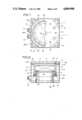
- FIG. 1is a plan view, partly in cross section, showing a portion of a rotational positioning device according to the present invention
- FIG. 2is a vertical sectional view corresponding to FIG. 1;
- FIG. 3is a perspective view of the rotational positioning device
- FIG. 4is a horizontal sectional view showing the mounted state of a rotational angle detecting means in the present invention
- FIG. 5is a sectional view taken along line V--V in FIG. 4;
- FIG. 6is a sectional view taken along line VI--VI in FIG. 1;
- FIG. 7is a sectional view taken along line VII--VII in FIG. 6;
- FIG. 8is an enlarged sectional view of the portion A of FIG. 2;
- FIG. 9is a sectional view showing a brake mechanism in the present invention.
- FIG. 10is a perspective view showing a conventional rotational positioning device.
- FIG. 1is a plan view, partly in cross section, showing a portion of a rotational positioning device according to the present invention
- FIG. 2is a vertical sectional view corresponding to FIG. 1
- FIG. 3is a perspective view of the rotational positioning device.
- the rotational positioning device of the present inventioncomprises a rotary table 10 for supporting a work 1, a servo motor 16 including a rotor 12 which secures the rotary table 10, a rotational angle detecting means 20 for detecting the rotational position of the rotary table 10, and a brake mechanism 30 for braking the rotation of the rotary table 10, wherein the servo motor 16, rotational angle detecting means 20, and brake mechanism 30 are accommodated in a casing 40.
- the rotary table 10has a through hole 11 for device wiring, bored at the center thereof and further, attaching holes 13, 13, . . . for securing the rotary table and other attaching holes 15, 15, . . . for supporting works, bored alternately at appropriate intervals on a circle concentric with the through hole 11.
- the servo motor 16comprises a bottom-provided cylindrical rotor 12 and a stator 14 disposed inside a cavity portion 17 of the rotor 12, which is adapted to undertake an open-loop control mode.
- the rotary table 10is secured on the upper/outer side of the rotor 12 by rotor securing bolts 2
- a disc 18is secured on the under/opening side by attaching bolts 3
- the stator 14is secured to a sectionally U-shaped attaching seat 44 which is in turn secured by securing bolts 43 to the upper edge of a cylindrical attaching ridge 42 projecting upward from a base 41.
- a turning roller bearing 19is interposed between the inner surface on the opening side of the rotor 12 of the motor 16 and the outer surface of the attaching seat 44 so that the rotor 12 and the rotary table 10 can rotate freely.
- the rotational angle detecting means 20is made of an encoder which comprises a light shielding board 22 secured to the side-wall opening portion of the rotor 12 of the servo motor 16 by securing screws 21, and an origin detecting unit 28 and an overrun detecting unit 29 in the form of sensors 26 and 27 each of which includes a light emitting element 24 and a light receiving element 25 disposed so as to face each other with interposition of a U-shaped folded portion 23 formed on the margin of the light shielding board 22, so that a mark (not shown) provided on the U-shaped folded portion 23 are optically detected by cooperation of the light emitting elements 24 and the light receiving elements 25 of these detecting units 28 and 29.
- the origin detecting unit 28 and the overrun detecting unit 29may be disposed at one spot.
- the brake mechanism 30is made of an electromagnetic brake which comprises an armature 31 detachable with respect to the disc 18 secured to the rotor 12 of the servo motor 16 and a solenoid 33 capable of attracting the armature in opposition to a spring 32 serving as a spring means for normally pressing the armature 31 against the disc 18.
- the surface of the armature 31 which faces the disc 18has a liner 34 attached thereto, and the armature 31 is bored with guide holes 37 which slidably fit with guide pins 36 provided in a fixing portion 35 in which the solenoid 33 is provided also, so that the contact/detach motion of the armature 33 resulting from the energization/deenergization of the solenoid 33 is stabilized.
- the casing 40is made in the form of an octagonal cylinder with its top portion 46 having an opening portion 45 which loosely accepts the rotor 12 of the servo motor 16, a ridge 47 circumferentially provided on the upper surface of the top portion 46 fits rotatably with a groove 10a formed in the opposing surface of the rotary table 10, and a labyrinth seal 48 is interposed between the ridge 47 and the groove 10a in their opposing areas, as shown in FIG. 8, so that the servo motor 16, rotational angle detecting means 20, and electromagnetic brake 30 accommodated in the casing 40 can be protected from external dust.
- one side wall of the casing 40has connectors 51 attached thereto which are used in wiring (not shown) the solenoid 33 of the electromagnetic brake 30 with a control unit 50 disposed in the cavity portion 17 defined by the attaching ridge 42 and the attaching seat 44, and the sensors 26 and 27 for the origin detecting unit 28 and the overrun detecting unit 29 are attached, respectively, to side walls 40b and 40c disposed on either side of the side wall 40a to which the connectors 51 are attached.
- a plurality of grooves 52are formed at appropriate positions in the upper surface of the base 41 so as to pass under the attaching ridge 42, so that cords (not shown) for connecting the connectors 51 and the control unit 50 are laid in these grooves 52.
- the function of indexing the rotational angle of the work 1 using the rotational positioning device configured as above of the present inventionis performed as follows. After the work 1 is supported by the rotary table 10, the servo motor 16 is energized to rotate the rotary table 10, and the mark provided on the light shielding board 22 is detected by the sensor 27 of the origin detecting unit 28, whereby a reference position is established. Then, an operation signal is sent from the control unit 50 to the servo motor 16 to energize the servo motor 16, whereby the rotary table 10 is rotated, and a predetermined rotational angle is detected in terms of the signal of the encoder accommodated in the servo motor 16, whereby the positioning of the work 1 is achieved.
- the resolution pertaining to the rotational angle of positioningis 1/655360 per revolution, or about 1.98"
- the positioningcan be performed at a high degree of accuracy.
- the solenoid 33 of the electromagnetic brake 30is deenergized, so that the urging force of the spring 22 presses the armature 31 against the disc 18, whereby the rotary table 10 is stopped and rendered stationary. Accordingly, since the rotary table 10 is instantly stopped and rendered stationary in case of emergency, the safety is assured even where the work 1 supported on the rotary table 10 is projecting sideways from the rotary table 10.
- the mode of use of the rotational positioning device of the present inventionis not necessarily limited to one horizontal state in which the rotary table 10 is located above the other part, and that the device can be used in any position, for example, in the other horizontal state in which the rotary table is located below the other part, or in the vertical state in which the rotary table 10 rotates in a vertical plane.
- the rotational positioning device of the embodimentcomprises the rotary table 10 for supporting the work 1, the servo motor 16 including the rotor 12 which secures the rotary table 10, the rotational angle detecting means 20 for detecting the rotational position of the rotary table 10, and the brake mechanism 30 for braking the rotation of the rotary table 10, wherein the servo motor 16, rotational angle detecting means 20, and brake mechanism 30 are accommodated in the casing 40; therefore, the device is small in size and easy to handle, is capable of high-speed rotational positioning and very accurate positioning, and provides a high degree of safety because the brake mechanism is built in.
Landscapes
- Engineering & Computer Science (AREA)
- Mechanical Engineering (AREA)
- Physics & Mathematics (AREA)
- Optics & Photonics (AREA)
- Machine Tool Units (AREA)
- Control Of Position Or Direction (AREA)
- Machine Tool Positioning Apparatuses (AREA)
- Connection Of Motors, Electrical Generators, Mechanical Devices, And The Like (AREA)
Abstract
Description
This invention relates to a rotational positioning device and more particularly, to an improvement of the rotational positioning device which is used in indexing the angle at a high degree of accuracy in the field of automated machines for semiconductor manufacturing/assembling, or of measuring, controlling, and testing machines for image processing/inspecting.
In general, this type of rotational positioning device comprises a rotary table for supporting a work or an article to be measured, a driving means for the rotary table, a rotational angle detecting means for detecting the rotational angle of the rotary table, and a brake mechanism for braking the rotary table. The drive system of the driving means includes a cam speed-reduction drive type, a gear/worm speed-reduction drive type, etc. The typical conventional rotational positioning device incorporates therein the worm speed-reduction drive system as shown in FIG. 10, which is featured in that a rotary table b for supporting a work a is rotatably supported by an index drive c, and this index drive c and a motor d serving as a drive source are connected by a speed reducer (worm speed reducer) e, a brake mechanism (electromagnetic brake) f, and a transmission mechanism (pulley h and belt i) g.
Therefore, the problems of the foregoing type of rotational positioning device of the prior art are that the speed of rotation of positioning is slow since the rotary table b is driven with intervention of the speed reducer e, the rotational angle detecting means must be provided externally, and a memory unit is needed since an open-loop control mode is employed, thus the components are increased and the size of the device itself is enlarged. Further problems are a low degree of resolution, the difficulty of indexing the angle accurately, etc.
In view of such circumstances, there has been demanded the development of small-sized rotational positioning devices of high rotational positioning speed which are also capable of achieving the indexing of angle at a high degree of accuracy.
Therefore, it is an object of the present invention to provide a rotational positioning device which comprises a servo motor for directly driving a rotary table without intervention of a speed reducer, a rotational angle detecting means, and a brake mechanism, all accommodated in its casing.
It is another object of the present invention to provide a superior rotational positioning device which is small in size and easy to handle, is capable of high-speed rotational positioning and very accurate positioning, and provides a high degree of safety because a brake mechanism is built in.
It is still another object of the present invention to provide a rotational positioning device which is featured in that the rotational angle of a rotary table is detected by a rotational angle detecting means when the rotary table is rotated by energizing a servo motor after a work is supported by the rotary table, and the rotational positioning of the work is achieved as the servo motor is controlled on the basis of the thus detected signal.
That is, the present invention resides in a rotational positioning device which comprises a rotary table for supporting a work, a servo motor including a rotor which secures the rotary table, a rotational angle detecting means for detecting the rotational position of the rotary table, and a brake mechanism for braking the rotation of the rotary table, wherein the servo motor, rotational angle detecting means, and brake mechanism are accommodated in a casing.
In the present invention, the rotational angle detecting means may be of any type as far as it can detect the rotational angle of the rotary table, but, preferably is an encoder which comprises a light shielding board secured to the rotor of the servo motor and an optional sensor for optically detecting a mark on the light shielding board.
Further, the brake mechanism may be of any type as far as it can brake the rotation of the rotary table when needed, but, preferably is an electromagnetic brake which comprises an armature detachable with respect to a disc secured to the rotor of the servo motor and a solenoid capable of attracting the armature in opposition to a spring means for normally pressing the armature against the disc.
As described above, accommodated in the casing are the servo motor including the rotor which secures the rotary table for supporting a work, the rotational angle detecting means for detecting the rotational position of the rotary table, and the brake mechanism for braking the rotation of the rotary table; therefore, the rotational angle of the rotary table is detected by the rotational angle detecting means as the rotary table is rotated by energizing the servo motor after a work is supported by the rotary table, and the rotational positioning of the work is achieved as the servo motor is controlled on the basis of the thus detected signal.
FIG. 1 is a plan view, partly in cross section, showing a portion of a rotational positioning device according to the present invention;
FIG. 2 is a vertical sectional view corresponding to FIG. 1;
FIG. 3 is a perspective view of the rotational positioning device;
FIG. 4 is a horizontal sectional view showing the mounted state of a rotational angle detecting means in the present invention;
FIG. 5 is a sectional view taken along line V--V in FIG. 4;
FIG. 6 is a sectional view taken along line VI--VI in FIG. 1;
FIG. 7 is a sectional view taken along line VII--VII in FIG. 6;
FIG. 8 is an enlarged sectional view of the portion A of FIG. 2;
FIG. 9 is a sectional view showing a brake mechanism in the present invention; and
FIG. 10 is a perspective view showing a conventional rotational positioning device.
The present invention will now be described in greater detail with reference to an embodiment shown in the accompanying drawings.
FIG. 1 is a plan view, partly in cross section, showing a portion of a rotational positioning device according to the present invention, FIG. 2 is a vertical sectional view corresponding to FIG. 1, and FIG. 3 is a perspective view of the rotational positioning device.
The rotational positioning device of the present invention comprises a rotary table 10 for supporting a work 1, a servo motor 16 including a rotor 12 which secures the rotary table 10, a rotational angle detecting means 20 for detecting the rotational position of the rotary table 10, and a brake mechanism 30 for braking the rotation of the rotary table 10, wherein the servo motor 16, rotational angle detecting means 20, and brake mechanism 30 are accommodated in a casing 40.
The rotary table 10 has a through hole 11 for device wiring, bored at the center thereof and further, attaching holes 13, 13, . . . for securing the rotary table and other attaching holes 15, 15, . . . for supporting works, bored alternately at appropriate intervals on a circle concentric with the through hole 11.
The servo motor 16 comprises a bottom-provided cylindrical rotor 12 and a stator 14 disposed inside a cavity portion 17 of the rotor 12, which is adapted to undertake an open-loop control mode. In the servo motor 16, the rotary table 10 is secured on the upper/outer side of the rotor 12 by rotor securing bolts 2, a disc 18 is secured on the under/opening side by attaching bolts 3, and the stator 14 is secured to a sectionally U-shaped attaching seat 44 which is in turn secured by securing bolts 43 to the upper edge of a cylindrical attaching ridge 42 projecting upward from a base 41. Further, a turning roller bearing 19 is interposed between the inner surface on the opening side of the rotor 12 of the motor 16 and the outer surface of the attaching seat 44 so that the rotor 12 and the rotary table 10 can rotate freely.
As shown in FIGS. 4 and 5, the rotational angle detecting means 20 is made of an encoder which comprises a light shielding board 22 secured to the side-wall opening portion of the rotor 12 of the servo motor 16 by securing screws 21, and an origin detecting unit 28 and an overrun detecting unit 29 in the form of sensors 26 and 27 each of which includes a light emitting element 24 and a light receiving element 25 disposed so as to face each other with interposition of a U-shaped folded portion 23 formed on the margin of the light shielding board 22, so that a mark (not shown) provided on the U-shaped folded portion 23 are optically detected by cooperation of the light emitting elements 24 and the light receiving elements 25 of these detecting units 28 and 29. Here, the origin detecting unit 28 and the overrun detecting unit 29 may be disposed at one spot.
As shown in FIG. 9, the brake mechanism 30 is made of an electromagnetic brake which comprises an armature 31 detachable with respect to the disc 18 secured to the rotor 12 of the servo motor 16 and a solenoid 33 capable of attracting the armature in opposition to a spring 32 serving as a spring means for normally pressing the armature 31 against the disc 18. Specifically, the surface of the armature 31 which faces the disc 18 has a liner 34 attached thereto, and the armature 31 is bored with guide holes 37 which slidably fit with guide pins 36 provided in a fixing portion 35 in which the solenoid 33 is provided also, so that the contact/detach motion of the armature 33 resulting from the energization/deenergization of the solenoid 33 is stabilized.
On the other hand, the casing 40 is made in the form of an octagonal cylinder with its top portion 46 having an opening portion 45 which loosely accepts the rotor 12 of the servo motor 16, a ridge 47 circumferentially provided on the upper surface of the top portion 46 fits rotatably with a groove 10a formed in the opposing surface of the rotary table 10, and a labyrinth seal 48 is interposed between the ridge 47 and the groove 10a in their opposing areas, as shown in FIG. 8, so that the servo motor 16, rotational angle detecting means 20, and electromagnetic brake 30 accommodated in the casing 40 can be protected from external dust. Further, one side wall of the casing 40 has connectors 51 attached thereto which are used in wiring (not shown) the solenoid 33 of the electromagnetic brake 30 with a control unit 50 disposed in the cavity portion 17 defined by the attaching ridge 42 and the attaching seat 44, and the sensors 26 and 27 for the origin detecting unit 28 and the overrun detecting unit 29 are attached, respectively, to side walls 40b and 40c disposed on either side of the side wall 40a to which the connectors 51 are attached.
Further, a plurality of grooves 52 are formed at appropriate positions in the upper surface of the base 41 so as to pass under the attaching ridge 42, so that cords (not shown) for connecting the connectors 51 and the control unit 50 are laid in these grooves 52.
The function of indexing the rotational angle of the work 1 using the rotational positioning device configured as above of the present invention is performed as follows. After the work 1 is supported by the rotary table 10, the servo motor 16 is energized to rotate the rotary table 10, and the mark provided on the light shielding board 22 is detected by the sensor 27 of the origin detecting unit 28, whereby a reference position is established. Then, an operation signal is sent from the control unit 50 to the servo motor 16 to energize the servo motor 16, whereby the rotary table 10 is rotated, and a predetermined rotational angle is detected in terms of the signal of the encoder accommodated in the servo motor 16, whereby the positioning of the work 1 is achieved. Here, since the resolution pertaining to the rotational angle of positioning is 1/655360 per revolution, or about 1.98", the positioning can be performed at a high degree of accuracy.
In case of emergency, e.g. where an electricity failure occurs during the positioning process, the solenoid 33 of the electromagnetic brake 30 is deenergized, so that the urging force of the spring 22 presses the armature 31 against the disc 18, whereby the rotary table 10 is stopped and rendered stationary. Accordingly, since the rotary table 10 is instantly stopped and rendered stationary in case of emergency, the safety is assured even where the work 1 supported on the rotary table 10 is projecting sideways from the rotary table 10. It should be noted that the mode of use of the rotational positioning device of the present invention is not necessarily limited to one horizontal state in which the rotary table 10 is located above the other part, and that the device can be used in any position, for example, in the other horizontal state in which the rotary table is located below the other part, or in the vertical state in which the rotary table 10 rotates in a vertical plane.
As described above, the rotational positioning device of the embodiment comprises the rotary table 10 for supporting the work 1, the servo motor 16 including the rotor 12 which secures the rotary table 10, the rotational angle detecting means 20 for detecting the rotational position of the rotary table 10, and the brake mechanism 30 for braking the rotation of the rotary table 10, wherein the servo motor 16, rotational angle detecting means 20, and brake mechanism 30 are accommodated in the casing 40; therefore, the device is small in size and easy to handle, is capable of high-speed rotational positioning and very accurate positioning, and provides a high degree of safety because the brake mechanism is built in.
While the invention has been particularly shown and described in reference to preferred embodiments thereof, it will be understood by those skilled in the art that changes in form and details may be made therein without departing from the spirit and scope of the invention.
Claims (4)
1. A rotational positioning device, comprising a rotary table for supporting a work piece ; a servo motor including a rotor which secures said rotary table ; a rotational angle detecting means for detecting the rotational position of said rotary table, wherein said rotational angle detecting means has a first portion coupled to said rotor and a second portion having a detector which detects a mark on said first portion; and a brake
means for braking the rotation of said rotary table, wherein said servo motor, said rotational angle detecting means, and said brake means are accommodated in a casing.
2. A rotational positioning device according to claim 1, wherein said brake means is an electromagnetic brake which comprises an armature detachable
relative to a disc secured to said rotor of said servo motor, and a solenoid capable of attracting said armature in opposition to a spring means for normally pressing said armature against said disc.
3. A rotational positioning device, comprising a rotary table for supporting a work piece; a servo motor including a rotor which secures said rotary table; a rotational angle detecting means for detecting the rotational position of said rotary table, wherein said rotational angle detecting means is an encoder which comprises a light shielding board secured to said rotor of said servo motor and an optical sensor for optically detecting a mark on said light shielding board; and a brake means for braking the rotation of said rotary table, wherein said servo motor, said rotational angle detecting means, and said brake means are accommodated in a casing.
4. A rotational positioning device according to claim 3, wherein said brake means is an electromagnetic brake which comprises an armature detachable relative to a disc secured to said rotor of said servo motor, and a solenoid capable of attracting said armature in opposition to a spring means for normally pressing said armature against said disc.
Applications Claiming Priority (2)
| Application Number | Priority Date | Filing Date | Title |
|---|---|---|---|
| JP1987170757UJP2554669Y2 (en) | 1987-11-10 | 1987-11-10 | Rotary positioning device |
| JP62-170757[U] | 1987-11-10 |
Publications (1)
| Publication Number | Publication Date |
|---|---|
| US4899998Atrue US4899998A (en) | 1990-02-13 |
Family
ID=15910821
Family Applications (1)
| Application Number | Title | Priority Date | Filing Date |
|---|---|---|---|
| US07/268,925Expired - Fee RelatedUS4899998A (en) | 1987-11-10 | 1988-11-09 | Rotational positioning device |
Country Status (3)
| Country | Link |
|---|---|
| US (1) | US4899998A (en) |
| JP (1) | JP2554669Y2 (en) |
| DE (1) | DE3838019C2 (en) |
Cited By (65)
| Publication number | Priority date | Publication date | Assignee | Title |
|---|---|---|---|---|
| US5845553A (en)* | 1995-01-05 | 1998-12-08 | Dayton-Phoenix Group, Inc. | Stator lamination jig system |
| WO2000039037A1 (en)* | 1998-12-23 | 2000-07-06 | Antas S.P.A. | Glass forming apparatus with improved carousel mechanism and method for control thereof |
| US20020075019A1 (en)* | 2000-12-04 | 2002-06-20 | Leonard Hayden | Wafer probe |
| EP1219386A1 (en)* | 2000-12-26 | 2002-07-03 | Mori Seiki Co., Ltd. | Automatic tool changer |
| US20020153877A1 (en)* | 2000-05-03 | 2002-10-24 | Harris Daniel L. | Indexing rotatable chuck for a probe station |
| US20030090278A1 (en)* | 2001-08-21 | 2003-05-15 | Kenneth Smith | Membrane probing system |
| US20040150416A1 (en)* | 1999-06-30 | 2004-08-05 | Cowan Clarence E. | Probe station thermal chuck with shielding for capacitive current |
| US20040154155A1 (en)* | 1998-07-14 | 2004-08-12 | Reed Gleason | Membrane probing system |
| US20040222807A1 (en)* | 2003-05-06 | 2004-11-11 | John Dunklee | Switched suspended conductor and connection |
| US20040232935A1 (en)* | 2003-05-23 | 2004-11-25 | Craig Stewart | Chuck for holding a device under test |
| US20050007581A1 (en)* | 2001-08-31 | 2005-01-13 | Harris Daniel L. | Optical testing device |
| US20050035777A1 (en)* | 1997-05-28 | 2005-02-17 | Randy Schwindt | Probe holder for testing of a test device |
| US20050088191A1 (en)* | 2003-10-22 | 2005-04-28 | Lesher Timothy E. | Probe testing structure |
| US20050099192A1 (en)* | 2002-11-25 | 2005-05-12 | John Dunklee | Probe station with low inductance path |
| US20050117986A1 (en)* | 2003-12-01 | 2005-06-02 | Martin Joseph H. | Vise-mounted milling machine collet indexer |
| US20050140384A1 (en)* | 2003-12-24 | 2005-06-30 | Peter Andrews | Chuck with integrated wafer support |
| US20050140386A1 (en)* | 2003-12-24 | 2005-06-30 | Eric Strid | Active wafer probe |
| US20050184744A1 (en)* | 1992-06-11 | 2005-08-25 | Cascademicrotech, Inc. | Wafer probe station having a skirting component |
| US20050231223A1 (en)* | 1996-08-08 | 2005-10-20 | Cascade Microtech, Inc. | Membrane probing system with local contact scrub |
| US20050248359A1 (en)* | 2000-02-25 | 2005-11-10 | Cascade Microtech, Inc. | Membrane probing system |
| US20050287685A1 (en)* | 2004-06-14 | 2005-12-29 | Mcfadden Bruce | Localizing a temperature of a device for testing |
| US20060006889A1 (en)* | 2004-07-07 | 2006-01-12 | Kenneth Smith | Probe head having a membrane suspended probe |
| US20060028200A1 (en)* | 2000-09-05 | 2006-02-09 | Cascade Microtech, Inc. | Chuck for holding a device under test |
| US20060043962A1 (en)* | 2004-09-13 | 2006-03-02 | Terry Burcham | Double sided probing structures |
| US20060103403A1 (en)* | 1995-04-14 | 2006-05-18 | Cascade Microtech, Inc. | System for evaluating probing networks |
| US20060132157A1 (en)* | 1992-06-11 | 2006-06-22 | Cascade Microtech, Inc. | Wafer probe station having environment control enclosure |
| US20060169897A1 (en)* | 2005-01-31 | 2006-08-03 | Cascade Microtech, Inc. | Microscope system for testing semiconductors |
| US7138810B2 (en) | 2002-11-08 | 2006-11-21 | Cascade Microtech, Inc. | Probe station with low noise characteristics |
| US7161363B2 (en) | 2002-05-23 | 2007-01-09 | Cascade Microtech, Inc. | Probe for testing a device under test |
| US7176705B2 (en) | 2004-06-07 | 2007-02-13 | Cascade Microtech, Inc. | Thermal optical chuck |
| US7178236B2 (en) | 1999-06-04 | 2007-02-20 | Cascade Microtech, Inc. | Method for constructing a membrane probe using a depression |
| US7190181B2 (en) | 1997-06-06 | 2007-03-13 | Cascade Microtech, Inc. | Probe station having multiple enclosures |
| US7221146B2 (en) | 2002-12-13 | 2007-05-22 | Cascade Microtech, Inc. | Guarded tub enclosure |
| US20070137433A1 (en)* | 2005-09-26 | 2007-06-21 | Amendolea Richard M | Rotary indexing table driven by an induction motor |
| US7271603B2 (en) | 2003-05-23 | 2007-09-18 | Cascade Microtech, Inc. | Shielded probe for testing a device under test |
| US7285969B2 (en) | 2002-11-13 | 2007-10-23 | Cascade Microtech, Inc. | Probe for combined signals |
| US20070285111A1 (en)* | 2006-06-12 | 2007-12-13 | Cascade Microtech, Inc. | Test structure and probe for differential signals |
| US20070285085A1 (en)* | 2006-06-12 | 2007-12-13 | Cascade Microtech, Inc. | Differential signal probing system |
| US20070285112A1 (en)* | 2006-06-12 | 2007-12-13 | Cascade Microtech, Inc. | On-wafer test structures |
| US20070285107A1 (en)* | 2006-06-12 | 2007-12-13 | Cascade Microtech, Inc. | Calibration structures for differential signal probing |
| US20080042675A1 (en)* | 2002-01-25 | 2008-02-21 | Cascade Microtech, Inc. | Probe station |
| US20080042670A1 (en)* | 2000-09-05 | 2008-02-21 | Cascade Microtech, Inc. | Probe station |
| GB2441312A (en)* | 2006-09-02 | 2008-03-05 | Cinetic Landis Grinding Ltd | Grinding apparatus |
| US20080163734A1 (en)* | 2005-07-12 | 2008-07-10 | Mueller Weingarten Ag | Dividing apparatus for automatic notching presses with a direct drive |
| US7449899B2 (en) | 2005-06-08 | 2008-11-11 | Cascade Microtech, Inc. | Probe for high frequency signals |
| US20090107310A1 (en)* | 2007-10-31 | 2009-04-30 | Kenji Arisue | Composite working lathe |
| US7535247B2 (en) | 2005-01-31 | 2009-05-19 | Cascade Microtech, Inc. | Interface for testing semiconductors |
| US20090152785A1 (en)* | 2005-09-12 | 2009-06-18 | Kabushiki Kaisha Yaskawa Denki | Alignment apparatus and original point returning method of alignment apparatus, turning table, translational table, machine including alignment apparatus and machine control system |
| US7609077B2 (en) | 2006-06-09 | 2009-10-27 | Cascade Microtech, Inc. | Differential signal probe with integral balun |
| US7619419B2 (en) | 2005-06-13 | 2009-11-17 | Cascade Microtech, Inc. | Wideband active-passive differential signal probe |
| US7656172B2 (en) | 2005-01-31 | 2010-02-02 | Cascade Microtech, Inc. | System for testing semiconductors |
| US20100085069A1 (en)* | 2008-10-06 | 2010-04-08 | Smith Kenneth R | Impedance optimized interface for membrane probe application |
| US20100127714A1 (en)* | 2008-11-24 | 2010-05-27 | Cascade Microtech, Inc. | Test system for flicker noise |
| US20100127725A1 (en)* | 2008-11-21 | 2010-05-27 | Smith Kenneth R | Replaceable coupon for a probing apparatus |
| US7876114B2 (en) | 2007-08-08 | 2011-01-25 | Cascade Microtech, Inc. | Differential waveguide probe |
| RU2438954C2 (en)* | 2008-02-23 | 2012-01-10 | Кронэс Аг | Conveyor |
| CN102990456A (en)* | 2011-09-08 | 2013-03-27 | 鸿富锦精密工业(深圳)有限公司 | Cam divider |
| EP2929971A1 (en)* | 2014-04-09 | 2015-10-14 | Fanuc Corporation | Electric discharge machine with rotary table |
| CN107932095A (en)* | 2017-10-24 | 2018-04-20 | 广州市昊志机电股份有限公司 | A kind of straight drive numerical control rotating platform |
| CN107932094A (en)* | 2017-10-24 | 2018-04-20 | 广州市昊志机电股份有限公司 | A kind of disc type electric machine directly turns platform |
| CN109352423A (en)* | 2018-09-29 | 2019-02-19 | 西安飞机工业(集团)有限责任公司 | Numerically-controlled machine tool AB pivot angle accuracy detection tooling and detection method |
| TWI662869B (en)* | 2016-01-28 | 2019-06-11 | 至禾機器工業有限公司 | Driving device of processing machine |
| CN111746959A (en)* | 2020-06-30 | 2020-10-09 | 西安精雕精密机械工程有限公司 | Closed-loop rotating bin suitable for automatic processing unit |
| CN113619984A (en)* | 2021-09-14 | 2021-11-09 | 珠海格力精密模具有限公司 | Intelligent storage device, intelligent processing equipment and control method thereof |
| TWI880243B (en)* | 2023-06-15 | 2025-04-11 | 寶嘉誠工業股份有限公司 | Multi-surface machining rotary work device |
Families Citing this family (9)
| Publication number | Priority date | Publication date | Assignee | Title |
|---|---|---|---|---|
| JP2573657Y2 (en)* | 1990-07-10 | 1998-06-04 | 日本精工株式会社 | Rotary axis clamping device |
| DE4035189A1 (en)* | 1990-11-06 | 1992-05-07 | Mauser Werke Oberndorf | DEVICE FOR ROTATING ANGLE POSITIONING A SHAFT PROVIDED WITH Eccentric Organs |
| US5676360A (en)* | 1995-07-11 | 1997-10-14 | Boucher; John N. | Machine tool rotary table locking apparatus |
| AT409606B (en)* | 2000-09-22 | 2002-09-25 | Ant Panhans Werkzeug Masch | PANEL |
| DE10149180A1 (en)* | 2001-10-04 | 2003-04-30 | Peiseler Gmbh & Co Kg | Rotary table |
| DE10332424B4 (en)* | 2003-07-16 | 2006-04-06 | Peiseler Gmbh & Co. Kg | Rotary table |
| CN107962406A (en)* | 2017-10-24 | 2018-04-27 | 广州市昊志机电股份有限公司 | A kind of low-speed direct driving large torque numerical control rotating platform |
| CN107972605B (en)* | 2017-11-21 | 2021-01-08 | 上海航天测控通信研究所 | High-precision vehicle-mounted rotary table |
| AT527057B1 (en)* | 2023-08-23 | 2024-10-15 | Muser Ing Miguel | PALLET GRIPPER |
Citations (3)
| Publication number | Priority date | Publication date | Assignee | Title |
|---|---|---|---|---|
| CH558708A (en)* | 1973-03-05 | 1975-02-14 | Hess Peter | Working table for mounting of precision watch components - has a rotating disc for the workpiece and a stepped drive |
| DE2549807A1 (en)* | 1975-11-06 | 1977-05-12 | Heinz Buchmeier | Remote controlled positioning of indexing tables - has sliders which engage table or clamping ring on forward and reverse movement |
| US4749067A (en)* | 1986-11-06 | 1988-06-07 | Lift-Tech International, Inc. | Solenoid and spring operated brake |
Family Cites Families (5)
| Publication number | Priority date | Publication date | Assignee | Title |
|---|---|---|---|---|
| IT1160079B (en)* | 1977-11-17 | 1987-03-04 | Nec Corp | RADAR FOR INDICATION OF MOVING OBJECTS |
| JPS57106384A (en)* | 1981-07-01 | 1982-07-02 | Mitsubishi Electric Corp | Controlling method for electromagnetic brake for hoist |
| JPS6077072U (en)* | 1983-11-01 | 1985-05-29 | パイオニア株式会社 | Disc player turntable rotation drive device |
| JPH0448114Y2 (en)* | 1984-10-03 | 1992-11-12 | ||
| JPS61239592A (en)* | 1985-04-15 | 1986-10-24 | トクデン株式会社 | Jacket chamber sealer for induction heating roller |
- 1987
- 1987-11-10JPJP1987170757Upatent/JP2554669Y2/ennot_activeExpired - Lifetime
- 1988
- 1988-11-09USUS07/268,925patent/US4899998A/ennot_activeExpired - Fee Related
- 1988-11-09DEDE3838019Apatent/DE3838019C2/ennot_activeExpired - Fee Related
Patent Citations (3)
| Publication number | Priority date | Publication date | Assignee | Title |
|---|---|---|---|---|
| CH558708A (en)* | 1973-03-05 | 1975-02-14 | Hess Peter | Working table for mounting of precision watch components - has a rotating disc for the workpiece and a stepped drive |
| DE2549807A1 (en)* | 1975-11-06 | 1977-05-12 | Heinz Buchmeier | Remote controlled positioning of indexing tables - has sliders which engage table or clamping ring on forward and reverse movement |
| US4749067A (en)* | 1986-11-06 | 1988-06-07 | Lift-Tech International, Inc. | Solenoid and spring operated brake |
Cited By (187)
| Publication number | Priority date | Publication date | Assignee | Title |
|---|---|---|---|---|
| US20050184744A1 (en)* | 1992-06-11 | 2005-08-25 | Cascademicrotech, Inc. | Wafer probe station having a skirting component |
| US7492147B2 (en) | 1992-06-11 | 2009-02-17 | Cascade Microtech, Inc. | Wafer probe station having a skirting component |
| US7589518B2 (en) | 1992-06-11 | 2009-09-15 | Cascade Microtech, Inc. | Wafer probe station having a skirting component |
| US20080106290A1 (en)* | 1992-06-11 | 2008-05-08 | Cascade Microtech, Inc. | Wafer probe station having environment control enclosure |
| US7595632B2 (en) | 1992-06-11 | 2009-09-29 | Cascade Microtech, Inc. | Wafer probe station having environment control enclosure |
| US7348787B2 (en) | 1992-06-11 | 2008-03-25 | Cascade Microtech, Inc. | Wafer probe station having environment control enclosure |
| US7330023B2 (en) | 1992-06-11 | 2008-02-12 | Cascade Microtech, Inc. | Wafer probe station having a skirting component |
| US20060132157A1 (en)* | 1992-06-11 | 2006-06-22 | Cascade Microtech, Inc. | Wafer probe station having environment control enclosure |
| US5845553A (en)* | 1995-01-05 | 1998-12-08 | Dayton-Phoenix Group, Inc. | Stator lamination jig system |
| US20060103403A1 (en)* | 1995-04-14 | 2006-05-18 | Cascade Microtech, Inc. | System for evaluating probing networks |
| US7164279B2 (en) | 1995-04-14 | 2007-01-16 | Cascade Microtech, Inc. | System for evaluating probing networks |
| US7321233B2 (en) | 1995-04-14 | 2008-01-22 | Cascade Microtech, Inc. | System for evaluating probing networks |
| US20070109001A1 (en)* | 1995-04-14 | 2007-05-17 | Cascade Microtech, Inc. | System for evaluating probing networks |
| US7893704B2 (en) | 1996-08-08 | 2011-02-22 | Cascade Microtech, Inc. | Membrane probing structure with laterally scrubbing contacts |
| US20050231223A1 (en)* | 1996-08-08 | 2005-10-20 | Cascade Microtech, Inc. | Membrane probing system with local contact scrub |
| US7541821B2 (en) | 1996-08-08 | 2009-06-02 | Cascade Microtech, Inc. | Membrane probing system with local contact scrub |
| US20090224783A1 (en)* | 1996-08-08 | 2009-09-10 | Cascade Microtech, Inc. | Membrane probing system with local contact scrub |
| US7109731B2 (en) | 1996-08-08 | 2006-09-19 | Cascade Microtech, Inc. | Membrane probing system with local contact scrub |
| US7504842B2 (en) | 1997-05-28 | 2009-03-17 | Cascade Microtech, Inc. | Probe holder for testing of a test device |
| US20050035777A1 (en)* | 1997-05-28 | 2005-02-17 | Randy Schwindt | Probe holder for testing of a test device |
| US7190181B2 (en) | 1997-06-06 | 2007-03-13 | Cascade Microtech, Inc. | Probe station having multiple enclosures |
| US7436170B2 (en) | 1997-06-06 | 2008-10-14 | Cascade Microtech, Inc. | Probe station having multiple enclosures |
| US7626379B2 (en) | 1997-06-06 | 2009-12-01 | Cascade Microtech, Inc. | Probe station having multiple enclosures |
| US20080048693A1 (en)* | 1997-06-06 | 2008-02-28 | Cascade Microtech, Inc. | Probe station having multiple enclosures |
| US7400155B2 (en) | 1998-07-14 | 2008-07-15 | Cascade Microtech, Inc. | Membrane probing system |
| US20040154155A1 (en)* | 1998-07-14 | 2004-08-12 | Reed Gleason | Membrane probing system |
| US8451017B2 (en) | 1998-07-14 | 2013-05-28 | Cascade Microtech, Inc. | Membrane probing method using improved contact |
| US20070283555A1 (en)* | 1998-07-14 | 2007-12-13 | Cascade Microtech, Inc. | Membrane probing system |
| US7681312B2 (en) | 1998-07-14 | 2010-03-23 | Cascade Microtech, Inc. | Membrane probing system |
| US7761986B2 (en) | 1998-07-14 | 2010-07-27 | Cascade Microtech, Inc. | Membrane probing method using improved contact |
| US20070245536A1 (en)* | 1998-07-14 | 2007-10-25 | Cascade Microtech,, Inc. | Membrane probing system |
| US20050136562A1 (en)* | 1998-07-14 | 2005-06-23 | Reed Gleason | Membrane probing system |
| US7266889B2 (en) | 1998-07-14 | 2007-09-11 | Cascade Microtech, Inc. | Membrane probing system |
| WO2000039037A1 (en)* | 1998-12-23 | 2000-07-06 | Antas S.P.A. | Glass forming apparatus with improved carousel mechanism and method for control thereof |
| US7533462B2 (en) | 1999-06-04 | 2009-05-19 | Cascade Microtech, Inc. | Method of constructing a membrane probe |
| US7178236B2 (en) | 1999-06-04 | 2007-02-20 | Cascade Microtech, Inc. | Method for constructing a membrane probe using a depression |
| US7138813B2 (en) | 1999-06-30 | 2006-11-21 | Cascade Microtech, Inc. | Probe station thermal chuck with shielding for capacitive current |
| US7616017B2 (en) | 1999-06-30 | 2009-11-10 | Cascade Microtech, Inc. | Probe station thermal chuck with shielding for capacitive current |
| US7292057B2 (en) | 1999-06-30 | 2007-11-06 | Cascade Microtech, Inc. | Probe station thermal chuck with shielding for capacitive current |
| US20070030021A1 (en)* | 1999-06-30 | 2007-02-08 | Cascade Microtech Inc. | Probe station thermal chuck with shielding for capacitive current |
| US20040150416A1 (en)* | 1999-06-30 | 2004-08-05 | Cowan Clarence E. | Probe station thermal chuck with shielding for capacitive current |
| US7148711B2 (en) | 2000-02-25 | 2006-12-12 | Cascade Microtech, Inc. | Membrane probing system |
| US20050248359A1 (en)* | 2000-02-25 | 2005-11-10 | Cascade Microtech, Inc. | Membrane probing system |
| US7403025B2 (en) | 2000-02-25 | 2008-07-22 | Cascade Microtech, Inc. | Membrane probing system |
| US6771090B2 (en) | 2000-05-03 | 2004-08-03 | Cascade Microtech, Inc. | Indexing rotatable chuck for a probe station |
| US20020153877A1 (en)* | 2000-05-03 | 2002-10-24 | Harris Daniel L. | Indexing rotatable chuck for a probe station |
| US6483336B1 (en) | 2000-05-03 | 2002-11-19 | Cascade Microtech, Inc. | Indexing rotatable chuck for a probe station |
| US20040217530A1 (en)* | 2000-05-03 | 2004-11-04 | Harris Daniel L. | Indexing rotatable chuck for a probe station |
| US6885197B2 (en) | 2000-05-03 | 2005-04-26 | Cascade Microtech, Inc. | Indexing rotatable chuck for a probe station |
| US7554322B2 (en) | 2000-09-05 | 2009-06-30 | Cascade Microtech, Inc. | Probe station |
| US20080042669A1 (en)* | 2000-09-05 | 2008-02-21 | Cascade Microtech, Inc. | Probe station |
| US7352168B2 (en) | 2000-09-05 | 2008-04-01 | Cascade Microtech, Inc. | Chuck for holding a device under test |
| US20080054884A1 (en)* | 2000-09-05 | 2008-03-06 | Cascade Microtech, Inc. | Chuck for holding a device under test |
| US7501810B2 (en) | 2000-09-05 | 2009-03-10 | Cascade Microtech, Inc. | Chuck for holding a device under test |
| US20080042642A1 (en)* | 2000-09-05 | 2008-02-21 | Cascade Microtech, Inc. | Chuck for holding a device under test |
| US20080042376A1 (en)* | 2000-09-05 | 2008-02-21 | Cascade Microtech, Inc. | Probe station |
| US20080042670A1 (en)* | 2000-09-05 | 2008-02-21 | Cascade Microtech, Inc. | Probe station |
| US7688062B2 (en) | 2000-09-05 | 2010-03-30 | Cascade Microtech, Inc. | Probe station |
| US7518358B2 (en) | 2000-09-05 | 2009-04-14 | Cascade Microtech, Inc. | Chuck for holding a device under test |
| US7514915B2 (en) | 2000-09-05 | 2009-04-07 | Cascade Microtech, Inc. | Chuck for holding a device under test |
| US20080042674A1 (en)* | 2000-09-05 | 2008-02-21 | John Dunklee | Chuck for holding a device under test |
| US7423419B2 (en) | 2000-09-05 | 2008-09-09 | Cascade Microtech, Inc. | Chuck for holding a device under test |
| US20100109695A1 (en)* | 2000-09-05 | 2010-05-06 | Cascade Microtech, Inc. | Chuck for holding a device under test |
| US7969173B2 (en) | 2000-09-05 | 2011-06-28 | Cascade Microtech, Inc. | Chuck for holding a device under test |
| US20060028200A1 (en)* | 2000-09-05 | 2006-02-09 | Cascade Microtech, Inc. | Chuck for holding a device under test |
| US7688097B2 (en) | 2000-12-04 | 2010-03-30 | Cascade Microtech, Inc. | Wafer probe |
| US7495461B2 (en) | 2000-12-04 | 2009-02-24 | Cascade Microtech, Inc. | Wafer probe |
| US7233160B2 (en) | 2000-12-04 | 2007-06-19 | Cascade Microtech, Inc. | Wafer probe |
| US7456646B2 (en) | 2000-12-04 | 2008-11-25 | Cascade Microtech, Inc. | Wafer probe |
| US7761983B2 (en) | 2000-12-04 | 2010-07-27 | Cascade Microtech, Inc. | Method of assembling a wafer probe |
| US20020075019A1 (en)* | 2000-12-04 | 2002-06-20 | Leonard Hayden | Wafer probe |
| EP1219386A1 (en)* | 2000-12-26 | 2002-07-03 | Mori Seiki Co., Ltd. | Automatic tool changer |
| US6719677B2 (en) | 2000-12-26 | 2004-04-13 | Mori Seiki Co., Ltd. | Automatic tool changer |
| US7492175B2 (en) | 2001-08-21 | 2009-02-17 | Cascade Microtech, Inc. | Membrane probing system |
| US20030090278A1 (en)* | 2001-08-21 | 2003-05-15 | Kenneth Smith | Membrane probing system |
| US7355420B2 (en) | 2001-08-21 | 2008-04-08 | Cascade Microtech, Inc. | Membrane probing system |
| US7268533B2 (en) | 2001-08-31 | 2007-09-11 | Cascade Microtech, Inc. | Optical testing device |
| US20050007581A1 (en)* | 2001-08-31 | 2005-01-13 | Harris Daniel L. | Optical testing device |
| US7368925B2 (en) | 2002-01-25 | 2008-05-06 | Cascade Microtech, Inc. | Probe station with two platens |
| US20080042675A1 (en)* | 2002-01-25 | 2008-02-21 | Cascade Microtech, Inc. | Probe station |
| US7304488B2 (en) | 2002-05-23 | 2007-12-04 | Cascade Microtech, Inc. | Shielded probe for high-frequency testing of a device under test |
| US7436194B2 (en) | 2002-05-23 | 2008-10-14 | Cascade Microtech, Inc. | Shielded probe with low contact resistance for testing a device under test |
| US7482823B2 (en) | 2002-05-23 | 2009-01-27 | Cascade Microtech, Inc. | Shielded probe for testing a device under test |
| US7161363B2 (en) | 2002-05-23 | 2007-01-09 | Cascade Microtech, Inc. | Probe for testing a device under test |
| US20070075716A1 (en)* | 2002-05-23 | 2007-04-05 | Cascade Microtech, Inc. | Probe for testing a device under test |
| US7489149B2 (en) | 2002-05-23 | 2009-02-10 | Cascade Microtech, Inc. | Shielded probe for testing a device under test |
| US7518387B2 (en) | 2002-05-23 | 2009-04-14 | Cascade Microtech, Inc. | Shielded probe for testing a device under test |
| US20080054922A1 (en)* | 2002-11-08 | 2008-03-06 | Cascade Microtech, Inc. | Probe station with low noise characteristics |
| US7550984B2 (en) | 2002-11-08 | 2009-06-23 | Cascade Microtech, Inc. | Probe station with low noise characteristics |
| US7295025B2 (en) | 2002-11-08 | 2007-11-13 | Cascade Microtech, Inc. | Probe station with low noise characteristics |
| US7138810B2 (en) | 2002-11-08 | 2006-11-21 | Cascade Microtech, Inc. | Probe station with low noise characteristics |
| US20080042673A1 (en)* | 2002-11-13 | 2008-02-21 | Cascade Microtech, Inc. | Probe for combined signals |
| US7285969B2 (en) | 2002-11-13 | 2007-10-23 | Cascade Microtech, Inc. | Probe for combined signals |
| US7417446B2 (en) | 2002-11-13 | 2008-08-26 | Cascade Microtech, Inc. | Probe for combined signals |
| US20080074129A1 (en)* | 2002-11-13 | 2008-03-27 | Cascade Microtech, Inc. | Probe for combined signals |
| US7453276B2 (en) | 2002-11-13 | 2008-11-18 | Cascade Microtech, Inc. | Probe for combined signals |
| US20050099192A1 (en)* | 2002-11-25 | 2005-05-12 | John Dunklee | Probe station with low inductance path |
| US7250779B2 (en) | 2002-11-25 | 2007-07-31 | Cascade Microtech, Inc. | Probe station with low inductance path |
| US7498828B2 (en) | 2002-11-25 | 2009-03-03 | Cascade Microtech, Inc. | Probe station with low inductance path |
| US7221146B2 (en) | 2002-12-13 | 2007-05-22 | Cascade Microtech, Inc. | Guarded tub enclosure |
| US7639003B2 (en) | 2002-12-13 | 2009-12-29 | Cascade Microtech, Inc. | Guarded tub enclosure |
| US20070194778A1 (en)* | 2002-12-13 | 2007-08-23 | Cascade Microtech, Inc. | Guarded tub enclosure |
| US20040222807A1 (en)* | 2003-05-06 | 2004-11-11 | John Dunklee | Switched suspended conductor and connection |
| US7468609B2 (en) | 2003-05-06 | 2008-12-23 | Cascade Microtech, Inc. | Switched suspended conductor and connection |
| US7221172B2 (en) | 2003-05-06 | 2007-05-22 | Cascade Microtech, Inc. | Switched suspended conductor and connection |
| US20070205784A1 (en)* | 2003-05-06 | 2007-09-06 | Cascade Microtech, Inc. | Switched suspended conductor and connection |
| US7492172B2 (en) | 2003-05-23 | 2009-02-17 | Cascade Microtech, Inc. | Chuck for holding a device under test |
| US7498829B2 (en) | 2003-05-23 | 2009-03-03 | Cascade Microtech, Inc. | Shielded probe for testing a device under test |
| US7271603B2 (en) | 2003-05-23 | 2007-09-18 | Cascade Microtech, Inc. | Shielded probe for testing a device under test |
| US7876115B2 (en) | 2003-05-23 | 2011-01-25 | Cascade Microtech, Inc. | Chuck for holding a device under test |
| US20040232935A1 (en)* | 2003-05-23 | 2004-11-25 | Craig Stewart | Chuck for holding a device under test |
| US7898273B2 (en) | 2003-05-23 | 2011-03-01 | Cascade Microtech, Inc. | Probe for testing a device under test |
| US7501842B2 (en) | 2003-05-23 | 2009-03-10 | Cascade Microtech, Inc. | Shielded probe for testing a device under test |
| US20090153167A1 (en)* | 2003-05-23 | 2009-06-18 | Craig Stewart | Chuck for holding a device under test |
| US20080042671A1 (en)* | 2003-05-23 | 2008-02-21 | Cascade Microtech, Inc. | Probe for testing a device under test |
| US7250626B2 (en) | 2003-10-22 | 2007-07-31 | Cascade Microtech, Inc. | Probe testing structure |
| US20050088191A1 (en)* | 2003-10-22 | 2005-04-28 | Lesher Timothy E. | Probe testing structure |
| US20080218187A1 (en)* | 2003-10-22 | 2008-09-11 | Cascade Microtech, Inc. | Probe testing structure |
| US8069491B2 (en) | 2003-10-22 | 2011-11-29 | Cascade Microtech, Inc. | Probe testing structure |
| US20050117986A1 (en)* | 2003-12-01 | 2005-06-02 | Martin Joseph H. | Vise-mounted milling machine collet indexer |
| US8087858B2 (en)* | 2003-12-01 | 2012-01-03 | Sherline Products Inc. | Vise-mounted milling machine collet indexer |
| US20080157796A1 (en)* | 2003-12-24 | 2008-07-03 | Peter Andrews | Chuck with integrated wafer support |
| US7759953B2 (en) | 2003-12-24 | 2010-07-20 | Cascade Microtech, Inc. | Active wafer probe |
| US20050140384A1 (en)* | 2003-12-24 | 2005-06-30 | Peter Andrews | Chuck with integrated wafer support |
| US7187188B2 (en) | 2003-12-24 | 2007-03-06 | Cascade Microtech, Inc. | Chuck with integrated wafer support |
| US20050140386A1 (en)* | 2003-12-24 | 2005-06-30 | Eric Strid | Active wafer probe |
| US7688091B2 (en) | 2003-12-24 | 2010-03-30 | Cascade Microtech, Inc. | Chuck with integrated wafer support |
| US7427868B2 (en) | 2003-12-24 | 2008-09-23 | Cascade Microtech, Inc. | Active wafer probe |
| US7362115B2 (en) | 2003-12-24 | 2008-04-22 | Cascade Microtech, Inc. | Chuck with integrated wafer support |
| US7504823B2 (en) | 2004-06-07 | 2009-03-17 | Cascade Microtech, Inc. | Thermal optical chuck |
| US7176705B2 (en) | 2004-06-07 | 2007-02-13 | Cascade Microtech, Inc. | Thermal optical chuck |
| US7330041B2 (en) | 2004-06-14 | 2008-02-12 | Cascade Microtech, Inc. | Localizing a temperature of a device for testing |
| US20050287685A1 (en)* | 2004-06-14 | 2005-12-29 | Mcfadden Bruce | Localizing a temperature of a device for testing |
| US7368927B2 (en) | 2004-07-07 | 2008-05-06 | Cascade Microtech, Inc. | Probe head having a membrane suspended probe |
| US7514944B2 (en) | 2004-07-07 | 2009-04-07 | Cascade Microtech, Inc. | Probe head having a membrane suspended probe |
| US20080157795A1 (en)* | 2004-07-07 | 2008-07-03 | Cascade Microtech, Inc. | Probe head having a membrane suspended probe |
| US20060006889A1 (en)* | 2004-07-07 | 2006-01-12 | Kenneth Smith | Probe head having a membrane suspended probe |
| US8013623B2 (en) | 2004-09-13 | 2011-09-06 | Cascade Microtech, Inc. | Double sided probing structures |
| US7420381B2 (en) | 2004-09-13 | 2008-09-02 | Cascade Microtech, Inc. | Double sided probing structures |
| US20060043962A1 (en)* | 2004-09-13 | 2006-03-02 | Terry Burcham | Double sided probing structures |
| US7535247B2 (en) | 2005-01-31 | 2009-05-19 | Cascade Microtech, Inc. | Interface for testing semiconductors |
| US7940069B2 (en) | 2005-01-31 | 2011-05-10 | Cascade Microtech, Inc. | System for testing semiconductors |
| US7656172B2 (en) | 2005-01-31 | 2010-02-02 | Cascade Microtech, Inc. | System for testing semiconductors |
| US7898281B2 (en) | 2005-01-31 | 2011-03-01 | Cascade Mircotech, Inc. | Interface for testing semiconductors |
| US20060169897A1 (en)* | 2005-01-31 | 2006-08-03 | Cascade Microtech, Inc. | Microscope system for testing semiconductors |
| US7449899B2 (en) | 2005-06-08 | 2008-11-11 | Cascade Microtech, Inc. | Probe for high frequency signals |
| US7619419B2 (en) | 2005-06-13 | 2009-11-17 | Cascade Microtech, Inc. | Wideband active-passive differential signal probe |
| US20080163734A1 (en)* | 2005-07-12 | 2008-07-10 | Mueller Weingarten Ag | Dividing apparatus for automatic notching presses with a direct drive |
| US20090152785A1 (en)* | 2005-09-12 | 2009-06-18 | Kabushiki Kaisha Yaskawa Denki | Alignment apparatus and original point returning method of alignment apparatus, turning table, translational table, machine including alignment apparatus and machine control system |
| US20070137433A1 (en)* | 2005-09-26 | 2007-06-21 | Amendolea Richard M | Rotary indexing table driven by an induction motor |
| US7638963B2 (en) | 2005-09-26 | 2009-12-29 | Centricity Corporation | Rotary indexing table driven by an induction motor |
| US7609077B2 (en) | 2006-06-09 | 2009-10-27 | Cascade Microtech, Inc. | Differential signal probe with integral balun |
| US7443186B2 (en) | 2006-06-12 | 2008-10-28 | Cascade Microtech, Inc. | On-wafer test structures for differential signals |
| US7723999B2 (en) | 2006-06-12 | 2010-05-25 | Cascade Microtech, Inc. | Calibration structures for differential signal probing |
| US20070285111A1 (en)* | 2006-06-12 | 2007-12-13 | Cascade Microtech, Inc. | Test structure and probe for differential signals |
| US7764072B2 (en) | 2006-06-12 | 2010-07-27 | Cascade Microtech, Inc. | Differential signal probing system |
| US7403028B2 (en) | 2006-06-12 | 2008-07-22 | Cascade Microtech, Inc. | Test structure and probe for differential signals |
| US20070285085A1 (en)* | 2006-06-12 | 2007-12-13 | Cascade Microtech, Inc. | Differential signal probing system |
| US20070285112A1 (en)* | 2006-06-12 | 2007-12-13 | Cascade Microtech, Inc. | On-wafer test structures |
| US20070285107A1 (en)* | 2006-06-12 | 2007-12-13 | Cascade Microtech, Inc. | Calibration structures for differential signal probing |
| US7750652B2 (en) | 2006-06-12 | 2010-07-06 | Cascade Microtech, Inc. | Test structure and probe for differential signals |
| GB2441312A (en)* | 2006-09-02 | 2008-03-05 | Cinetic Landis Grinding Ltd | Grinding apparatus |
| US7876114B2 (en) | 2007-08-08 | 2011-01-25 | Cascade Microtech, Inc. | Differential waveguide probe |
| US8051543B2 (en)* | 2007-10-31 | 2011-11-08 | Yamazaki Mazak Corporation | Composite working lathe |
| US20090107310A1 (en)* | 2007-10-31 | 2009-04-30 | Kenji Arisue | Composite working lathe |
| RU2438954C2 (en)* | 2008-02-23 | 2012-01-10 | Кронэс Аг | Conveyor |
| US20100085069A1 (en)* | 2008-10-06 | 2010-04-08 | Smith Kenneth R | Impedance optimized interface for membrane probe application |
| US7888957B2 (en) | 2008-10-06 | 2011-02-15 | Cascade Microtech, Inc. | Probing apparatus with impedance optimized interface |
| US9429638B2 (en) | 2008-11-21 | 2016-08-30 | Cascade Microtech, Inc. | Method of replacing an existing contact of a wafer probing assembly |
| US20100127725A1 (en)* | 2008-11-21 | 2010-05-27 | Smith Kenneth R | Replaceable coupon for a probing apparatus |
| US8410806B2 (en) | 2008-11-21 | 2013-04-02 | Cascade Microtech, Inc. | Replaceable coupon for a probing apparatus |
| US10267848B2 (en) | 2008-11-21 | 2019-04-23 | Formfactor Beaverton, Inc. | Method of electrically contacting a bond pad of a device under test with a probe |
| US8319503B2 (en) | 2008-11-24 | 2012-11-27 | Cascade Microtech, Inc. | Test apparatus for measuring a characteristic of a device under test |
| US20100127714A1 (en)* | 2008-11-24 | 2010-05-27 | Cascade Microtech, Inc. | Test system for flicker noise |
| CN102990456A (en)* | 2011-09-08 | 2013-03-27 | 鸿富锦精密工业(深圳)有限公司 | Cam divider |
| US8430000B2 (en)* | 2011-09-08 | 2013-04-30 | Hong Fu Jin Precision Industry (Shenzhen) Co., Ltd. | Cam indexer |
| CN102990456B (en)* | 2011-09-08 | 2015-04-15 | 鸿富锦精密工业(深圳)有限公司 | cam splitter |
| US20150290734A1 (en)* | 2014-04-09 | 2015-10-15 | Fanuc Corporation | Electric discharge machine with rotary table |
| US10052704B2 (en)* | 2014-04-09 | 2018-08-21 | Fanuc Corporation | Electric discharge machine with rotary table |
| EP2929971A1 (en)* | 2014-04-09 | 2015-10-14 | Fanuc Corporation | Electric discharge machine with rotary table |
| TWI662869B (en)* | 2016-01-28 | 2019-06-11 | 至禾機器工業有限公司 | Driving device of processing machine |
| CN107932095A (en)* | 2017-10-24 | 2018-04-20 | 广州市昊志机电股份有限公司 | A kind of straight drive numerical control rotating platform |
| CN107932094A (en)* | 2017-10-24 | 2018-04-20 | 广州市昊志机电股份有限公司 | A kind of disc type electric machine directly turns platform |
| CN109352423A (en)* | 2018-09-29 | 2019-02-19 | 西安飞机工业(集团)有限责任公司 | Numerically-controlled machine tool AB pivot angle accuracy detection tooling and detection method |
| CN111746959A (en)* | 2020-06-30 | 2020-10-09 | 西安精雕精密机械工程有限公司 | Closed-loop rotating bin suitable for automatic processing unit |
| CN113619984A (en)* | 2021-09-14 | 2021-11-09 | 珠海格力精密模具有限公司 | Intelligent storage device, intelligent processing equipment and control method thereof |
| TWI880243B (en)* | 2023-06-15 | 2025-04-11 | 寶嘉誠工業股份有限公司 | Multi-surface machining rotary work device |
Also Published As
| Publication number | Publication date |
|---|---|
| DE3838019C2 (en) | 1996-02-01 |
| JP2554669Y2 (en) | 1997-11-17 |
| JPH0176611U (en) | 1989-05-24 |
| DE3838019A1 (en) | 1989-05-18 |
Similar Documents
| Publication | Publication Date | Title |
|---|---|---|
| US4899998A (en) | Rotational positioning device | |
| US5053685A (en) | High precision linear actuator | |
| US5793128A (en) | Encoder and motor with an encoder | |
| US4899048A (en) | Focused optical beam encoder of position | |
| US3524067A (en) | Compact line grating position sensing device | |
| EP4349546B1 (en) | Robot arm and joint module | |
| KR920006481B1 (en) | Positioning apparatus for an automatic carrier system | |
| US4639595A (en) | Optical rotary encoder | |
| KR20110121602A (en) | Mounting method of modular rotary encoder and modular rotary encoder | |
| CN210225188U (en) | Mounting structure of rotary member of encoder | |
| WO2021090551A1 (en) | Rotational positioning device | |
| EP0285053A2 (en) | Fiber optic sensing system and method across working air gap of an electric motor | |
| US5176085A (en) | Position detecting device | |
| US20240181632A1 (en) | Robot drive module | |
| KR102054875B1 (en) | Permeable optical encoder | |
| US4107745A (en) | Tape speed control apparatus | |
| JP2003228138A (en) | Optical scanning apparatus and self-propelled light bar assembly | |
| US20040183001A1 (en) | Device for measurement of rotational angle | |
| CN104659957A (en) | Direct-driven motor and magnetic encoder synchronization device of sewing machine | |
| JPH0111188Y2 (en) | ||
| JPS57191827A (en) | Moving magnetic head with reference position detecting mechanism | |
| JPS63167226A (en) | spectrophotometer | |
| CN216649479U (en) | Drive motor and power equipment | |
| US11876416B2 (en) | Rotary machine having a position sensor | |
| KR200205138Y1 (en) | Magnification Converter |
Legal Events
| Date | Code | Title | Description |
|---|---|---|---|
| FPAY | Fee payment | Year of fee payment:4 | |
| FPAY | Fee payment | Year of fee payment:8 | |
| FEPP | Fee payment procedure | Free format text:PAYOR NUMBER ASSIGNED (ORIGINAL EVENT CODE: ASPN); ENTITY STATUS OF PATENT OWNER: LARGE ENTITY | |
| AS | Assignment | Owner name:THK CO., LTD., JAPAN Free format text:ASSIGNMENT OF ASSIGNORS INTEREST;ASSIGNOR:TERAMACHI, HIROSHI;REEL/FRAME:009719/0127 Effective date:19981113 | |
| REMI | Maintenance fee reminder mailed | ||
| LAPS | Lapse for failure to pay maintenance fees | ||
| STCH | Information on status: patent discontinuation | Free format text:PATENT EXPIRED DUE TO NONPAYMENT OF MAINTENANCE FEES UNDER 37 CFR 1.362 | |
| FP | Lapsed due to failure to pay maintenance fee | Effective date:20020213 |