US4898197A - Cleaning of tubes using projectiles - Google Patents
Cleaning of tubes using projectilesDownload PDFInfo
- Publication number
- US4898197A US4898197AUS07/120,942US12094287AUS4898197AUS 4898197 AUS4898197 AUS 4898197AUS 12094287 AUS12094287 AUS 12094287AUS 4898197 AUS4898197 AUS 4898197A
- Authority
- US
- United States
- Prior art keywords
- projectile
- tube
- cleaning
- unitary
- liquid
- Prior art date
- Legal status (The legal status is an assumption and is not a legal conclusion. Google has not performed a legal analysis and makes no representation as to the accuracy of the status listed.)
- Expired - Lifetime
Links
- 238000004140cleaningMethods0.000titleclaimsabstractdescription36
- 239000007788liquidSubstances0.000claimsabstractdescription22
- 238000000034methodMethods0.000claimsabstractdescription21
- XLYOFNOQVPJJNP-UHFFFAOYSA-NwaterSubstancesOXLYOFNOQVPJJNP-UHFFFAOYSA-N0.000claimsdescription11
- 238000007790scrapingMethods0.000claimsdescription5
- 230000001680brushing effectEffects0.000claimsdescription3
- 239000007787solidSubstances0.000claimsdescription3
- 230000000694effectsEffects0.000claimsdescription2
- 230000008569processEffects0.000abstractdescription5
- 230000001939inductive effectEffects0.000abstract1
- 239000000356contaminantSubstances0.000description10
- 239000000463materialSubstances0.000description10
- 230000009471actionEffects0.000description7
- 239000012530fluidSubstances0.000description6
- 238000006243chemical reactionMethods0.000description2
- 230000007246mechanismEffects0.000description2
- 230000035939shockEffects0.000description2
- 230000015572biosynthetic processEffects0.000description1
- 230000001419dependent effectEffects0.000description1
- 238000010586diagramMethods0.000description1
- 238000006073displacement reactionMethods0.000description1
- 230000006872improvementEffects0.000description1
- 230000003993interactionEffects0.000description1
- 239000000203mixtureSubstances0.000description1
- 230000007704transitionEffects0.000description1
- 230000005514two-phase flowEffects0.000description1
- 238000011144upstream manufacturingMethods0.000description1
Images
Classifications
- F—MECHANICAL ENGINEERING; LIGHTING; HEATING; WEAPONS; BLASTING
- F28—HEAT EXCHANGE IN GENERAL
- F28G—CLEANING OF INTERNAL OR EXTERNAL SURFACES OF HEAT-EXCHANGE OR HEAT-TRANSFER CONDUITS, e.g. WATER TUBES OR BOILERS
- F28G7/00—Cleaning by vibration or pressure waves
- B—PERFORMING OPERATIONS; TRANSPORTING
- B08—CLEANING
- B08B—CLEANING IN GENERAL; PREVENTION OF FOULING IN GENERAL
- B08B9/00—Cleaning hollow articles by methods or apparatus specially adapted thereto
- B08B9/02—Cleaning pipes or tubes or systems of pipes or tubes
- B08B9/027—Cleaning the internal surfaces; Removal of blockages
- B08B9/04—Cleaning the internal surfaces; Removal of blockages using cleaning devices introduced into and moved along the pipes
- B08B9/053—Cleaning the internal surfaces; Removal of blockages using cleaning devices introduced into and moved along the pipes moved along the pipes by a fluid, e.g. by fluid pressure or by suction
- B08B9/055—Cleaning the internal surfaces; Removal of blockages using cleaning devices introduced into and moved along the pipes moved along the pipes by a fluid, e.g. by fluid pressure or by suction the cleaning devices conforming to, or being conformable to, substantially the same cross-section of the pipes, e.g. pigs or moles
- B08B9/0555—Gelled or degradable pigs
- B08B9/0556—Gelled or degradable pigs at least partially formed of a frozen liquid or gas
- F—MECHANICAL ENGINEERING; LIGHTING; HEATING; WEAPONS; BLASTING
- F28—HEAT EXCHANGE IN GENERAL
- F28G—CLEANING OF INTERNAL OR EXTERNAL SURFACES OF HEAT-EXCHANGE OR HEAT-TRANSFER CONDUITS, e.g. WATER TUBES OR BOILERS
- F28G1/00—Non-rotary, e.g. reciprocated, appliances
- F28G1/12—Fluid-propelled scrapers, bullets, or like solid bodies
Definitions
- the most common forms of industrial heat transfer devicesare boilers, condensers and heat exchangers.
- the usual embodiment of these devicesis an outer shell or casing through which passes a plurality of tubes.
- One fluid mediumpasses through the tubes and another hotter or colder fluid medium passes through the shell around the outside of the tubes, giving up heat to or taking up heat from the first said fluid medium.
- tube cleaningThe most common forms of tube cleaning are pigging and high pressure water lancing.
- a pig fitted with scraping, brushing or abrading elementsis forced through a tube at low speed by means of fluid pressure, mechanically removing contaminant material.
- a lancecomprising a long rigid or flexible tube which terminates in a head provided with a plurality of orifices is inserted into a tube and highly pressurized water or some other suitable liquid cleaning medium is supplied through the said tube to the said orifices in the head.
- the lanceis normally inserted into a tube by hand and energetic jets of water or cleaning medium emitted from the said orifices scour contaminant material from the walls of the tube and flush it away.
- the present inventiondiscloses a method of tube cleaning which is a continuation-in-part of that disclosed in patent application No. 858,859 and which involves the propelling of a projectile into and through a tube by means of a more or less instantaneous release against it of a supply of liquid cleaning medium at high pressure.
- the pressure of the liquid cleaning medium at its sourceis between 1,000 and 12,000 psi.
- the regime of operation of the tube cleaning apparatuswhich is of immediate interest is that in which lightly contaminated pipes are cleaned by using a flow of high pressure liquid cleaning medium to propel a loosely fitting projectile at high speed down the tube.
- the fact that the projectile fits loosely into the tubesuggests that the projectile itself does not mechanically scrape the contaminant material from the tube walls.
- the contaminant material removed from the tube wallsappears in the liquid cleaning medium following the projectile rather than ahead of the projectile. Little of the liquid cleaning medium is found to be ahead of the projectile at the end of its travel implying that strong wall shear due to high speed forward flow through the annular space between the tube wall and the projectile is also ruled out as a possible mechanism.
- Reynolds Numberis a measure of the ratio of the inertial forces to the viscous forces and is defined as ##EQU1## where L is a typical dimension of the flow, ⁇ is the density of the fluid, U the flow velocity, and ⁇ is the molecular viscosity of the fluid. Flows with the same Reynolds Number and geometry can be expected to be dynamically similar. The density of water at 20° C. is 998 Kg/m 3 . Taking the tube diameter as the dimension L, a typical Reynolds Number for the flows being considered is 1.2 ⁇ 10 5 .
- a source of pressurized water or other suitable cleaning mediumPreferably, this is a "Triplex" positive displacement type pump, the output of which produces a pulsed flow containing up to 6,000 pulses per minute.
- the said pumpis connected by conduits of suitable internal diameter to a quick opening valve also of suitable internal diameter, the said valve being mounted on or close to a moveable launcher.
- the said valveis connected to the said launcher which can be positioned collinear with and sealed to the opening of a tube to be cleaned.
- the said launchermay be simple in arrangement or may incorporate means to supply a projectile from a storage magazine to each tube to be cleaned. A projectile is placed in the end of a tube to be cleaned and the said launcher sealed to the opening of the tube.
- projectilesare simple, unitary and incompressible and, in their simplest form, are cylindrical in shape.
- projectilesmay be made in other shapes ranging from that of a modified cylinder through to spherical.
- the diameter of a projectileis selected for a particular tube cleaning task. In the case of a tube contaminated with a light laminar layer, a projectile is selected with a diameter such that it would be a light sliding fit in the clean tube. In the case of a tube with a heavier laminar layer of contaminant material, the diameter of the projectile is selected to approximate the average lumen of the contaminated tube.
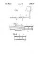
- FIG. 1is a diagram of the arrangement of a cleaning medium supply system
- FIG. 2depicts a longitudinal cross-sectional view of a launcher sealingly engaged to the end of a tube to be cleaned
- FIG. 3depicts a longitudinal cross-sectional view of a projectile travelling in a tube.
- pump 1takes liquid cleaning medium from reservoir 2 and passes it through conduit 3 to optional accumulator 4.
- the opening of quick opening valve 5permits pump output flow or the contents of accumulator 4 to pass through launcher 6 to tube to be cleaned 7.
- launcher 6is sealingly engaged with the opening of tube to be cleaned 7.
- Projectile 8is sized to conform to the average lumen created by contaminant material 9.
Landscapes
- Engineering & Computer Science (AREA)
- Chemical & Material Sciences (AREA)
- Mechanical Engineering (AREA)
- Combustion & Propulsion (AREA)
- General Engineering & Computer Science (AREA)
- Dispersion Chemistry (AREA)
- Physics & Mathematics (AREA)
- Fluid Mechanics (AREA)
- Cleaning In General (AREA)
Abstract
Description
Claims (11)
Priority Applications (1)
| Application Number | Priority Date | Filing Date | Title |
|---|---|---|---|
| US07/120,942US4898197A (en) | 1983-03-11 | 1987-11-16 | Cleaning of tubes using projectiles |
Applications Claiming Priority (4)
| Application Number | Priority Date | Filing Date | Title |
|---|---|---|---|
| AU12433/83 | 1983-03-11 | ||
| AU18165/83AAU571845B2 (en) | 1983-08-19 | 1983-08-19 | Pig, launcher and catcher for tube or pipe cleaning |
| WOPCT/AU84/00159 | 1984-08-17 | ||
| US07/120,942US4898197A (en) | 1983-03-11 | 1987-11-16 | Cleaning of tubes using projectiles |
Related Parent Applications (1)
| Application Number | Title | Priority Date | Filing Date |
|---|---|---|---|
| US06/858,859Continuation-In-PartUS4724007A (en) | 1983-08-19 | 1986-04-30 | Method of cleaning pipes and tubes by pigging using water hammer shock waves |
Publications (1)
| Publication Number | Publication Date |
|---|---|
| US4898197Atrue US4898197A (en) | 1990-02-06 |
Family
ID=25617059
Family Applications (1)
| Application Number | Title | Priority Date | Filing Date |
|---|---|---|---|
| US07/120,942Expired - LifetimeUS4898197A (en) | 1983-03-11 | 1987-11-16 | Cleaning of tubes using projectiles |
Country Status (1)
| Country | Link |
|---|---|
| US (1) | US4898197A (en) |
Cited By (14)
| Publication number | Priority date | Publication date | Assignee | Title |
|---|---|---|---|---|
| US5056587A (en)* | 1990-09-07 | 1991-10-15 | Halliburton Company | Method for deslagging a boiler |
| US5083500A (en)* | 1989-04-10 | 1992-01-28 | Superior Environmental Services, Inc. | Radon treatment system and method |
| US5221047A (en)* | 1991-08-13 | 1993-06-22 | Gmfanuc Robotics Corporation | Method and system for cleaning a paint supply line and changing paint colors in production paint operations |
| US5300152A (en)* | 1992-07-27 | 1994-04-05 | Atlantic Richfield Company | Method of cleaning tubular with frozen layered gelatin pig |
| EP0752282A1 (en)* | 1995-06-12 | 1997-01-08 | AIMM Technologies, Inc. | Method and apparatus for the induction of sonics, subsonics and/or supersonics into the interior of open-ended columns |
| EP1102018A1 (en)* | 1999-11-16 | 2001-05-23 | Matsushita Electric Industrial Co., Ltd. | Piping cleaning method of air conditioner, compounds used therein, and piping cleaning apparatus |
| US6485577B1 (en) | 2000-01-07 | 2002-11-26 | Robert Kiholm | Pipe pig formed of frozen product |
| US20030140944A1 (en)* | 2000-01-11 | 2003-07-31 | Quarini Giuseppe L. | Cleaning and separation in conduits |
| WO2005007308A1 (en)* | 2003-07-17 | 2005-01-27 | Jemne Rolf G | Apparatus and method for internal cleaning of pipes and tubes |
| US20070015002A1 (en)* | 2005-07-14 | 2007-01-18 | Ut-Battele, Llc | Oxygen-donor and catalytic coatings of metal oxides and metals |
| EP1932601A1 (en)* | 2006-12-15 | 2008-06-18 | Honeywell International Inc. | System and method for scrubbing CMP slurry systems |
| US8623301B1 (en) | 2008-04-09 | 2014-01-07 | C3 International, Llc | Solid oxide fuel cells, electrolyzers, and sensors, and methods of making and using the same |
| US9067246B2 (en) | 2012-09-14 | 2015-06-30 | R 2 Solutions LLC | Water service line repair |
| US11226062B2 (en)* | 2019-02-18 | 2022-01-18 | Tropicana Products, Inc. | Method for minimizing material mixing during transitions in a material processing system |
Citations (15)
| Publication number | Priority date | Publication date | Assignee | Title |
|---|---|---|---|---|
| US1034301A (en)* | 1912-01-31 | 1912-07-30 | George W Redeker | Cleaning process for water-pipes. |
| US1806270A (en)* | 1928-07-19 | 1931-05-19 | Elliott Co | Apparatus for cleaning tubes |
| US2874078A (en)* | 1954-04-14 | 1959-02-17 | Alberto G Reinhart | Pipe cleaning method |
| US3148689A (en)* | 1960-11-22 | 1964-09-15 | Colorado Interstate Gas Compan | Method and system for gas transmission |
| US3409470A (en)* | 1966-06-27 | 1968-11-05 | Dow Chemical Co | Cyclic water hammer method |
| US3451091A (en)* | 1968-02-23 | 1969-06-24 | James W Wallace | Device for cleaning pipes and tubes |
| US3531813A (en)* | 1968-09-17 | 1970-10-06 | Combustion Eng | Tube cleaning pellet gun |
| US3562014A (en)* | 1969-05-16 | 1971-02-09 | Exxon Production Research Co | Pipeline scraper launching system |
| US3631555A (en)* | 1970-03-09 | 1972-01-04 | Combustion Eng | Tube-cleaning pellet gun |
| US3914815A (en)* | 1974-09-20 | 1975-10-28 | Fuji Seiki Machine Works | Pipe inside cleaning device |
| US4252255A (en)* | 1979-03-13 | 1981-02-24 | David Henderson | Mechanism for purging a plural component mixing and dispensing gun |
| US4353414A (en)* | 1980-08-21 | 1982-10-12 | Water Services Of America, Inc. | Heat exchanger tube cleaning |
| US4467488A (en)* | 1982-12-23 | 1984-08-28 | Combustion Engineering, Inc. | Device for final cleaning of tubes |
| US4716611A (en)* | 1983-03-11 | 1988-01-05 | Lacress Nominees Pty., Ltd. | Apparatus for cleaning pipes, tubes, and the like by launching pigs |
| US4724007A (en)* | 1983-08-19 | 1988-02-09 | Lacress Nominees Pty. Ltd. | Method of cleaning pipes and tubes by pigging using water hammer shock waves |
- 1987
- 1987-11-16USUS07/120,942patent/US4898197A/ennot_activeExpired - Lifetime
Patent Citations (15)
| Publication number | Priority date | Publication date | Assignee | Title |
|---|---|---|---|---|
| US1034301A (en)* | 1912-01-31 | 1912-07-30 | George W Redeker | Cleaning process for water-pipes. |
| US1806270A (en)* | 1928-07-19 | 1931-05-19 | Elliott Co | Apparatus for cleaning tubes |
| US2874078A (en)* | 1954-04-14 | 1959-02-17 | Alberto G Reinhart | Pipe cleaning method |
| US3148689A (en)* | 1960-11-22 | 1964-09-15 | Colorado Interstate Gas Compan | Method and system for gas transmission |
| US3409470A (en)* | 1966-06-27 | 1968-11-05 | Dow Chemical Co | Cyclic water hammer method |
| US3451091A (en)* | 1968-02-23 | 1969-06-24 | James W Wallace | Device for cleaning pipes and tubes |
| US3531813A (en)* | 1968-09-17 | 1970-10-06 | Combustion Eng | Tube cleaning pellet gun |
| US3562014A (en)* | 1969-05-16 | 1971-02-09 | Exxon Production Research Co | Pipeline scraper launching system |
| US3631555A (en)* | 1970-03-09 | 1972-01-04 | Combustion Eng | Tube-cleaning pellet gun |
| US3914815A (en)* | 1974-09-20 | 1975-10-28 | Fuji Seiki Machine Works | Pipe inside cleaning device |
| US4252255A (en)* | 1979-03-13 | 1981-02-24 | David Henderson | Mechanism for purging a plural component mixing and dispensing gun |
| US4353414A (en)* | 1980-08-21 | 1982-10-12 | Water Services Of America, Inc. | Heat exchanger tube cleaning |
| US4467488A (en)* | 1982-12-23 | 1984-08-28 | Combustion Engineering, Inc. | Device for final cleaning of tubes |
| US4716611A (en)* | 1983-03-11 | 1988-01-05 | Lacress Nominees Pty., Ltd. | Apparatus for cleaning pipes, tubes, and the like by launching pigs |
| US4724007A (en)* | 1983-08-19 | 1988-02-09 | Lacress Nominees Pty. Ltd. | Method of cleaning pipes and tubes by pigging using water hammer shock waves |
Cited By (19)
| Publication number | Priority date | Publication date | Assignee | Title |
|---|---|---|---|---|
| US5083500A (en)* | 1989-04-10 | 1992-01-28 | Superior Environmental Services, Inc. | Radon treatment system and method |
| US5056587A (en)* | 1990-09-07 | 1991-10-15 | Halliburton Company | Method for deslagging a boiler |
| US5221047A (en)* | 1991-08-13 | 1993-06-22 | Gmfanuc Robotics Corporation | Method and system for cleaning a paint supply line and changing paint colors in production paint operations |
| US5300152A (en)* | 1992-07-27 | 1994-04-05 | Atlantic Richfield Company | Method of cleaning tubular with frozen layered gelatin pig |
| EP0752282A1 (en)* | 1995-06-12 | 1997-01-08 | AIMM Technologies, Inc. | Method and apparatus for the induction of sonics, subsonics and/or supersonics into the interior of open-ended columns |
| EP1102018A1 (en)* | 1999-11-16 | 2001-05-23 | Matsushita Electric Industrial Co., Ltd. | Piping cleaning method of air conditioner, compounds used therein, and piping cleaning apparatus |
| US6485577B1 (en) | 2000-01-07 | 2002-11-26 | Robert Kiholm | Pipe pig formed of frozen product |
| US6916383B2 (en)* | 2000-01-11 | 2005-07-12 | University Of Bristol | Cleaning and separation in conduits |
| US20030140944A1 (en)* | 2000-01-11 | 2003-07-31 | Quarini Giuseppe L. | Cleaning and separation in conduits |
| WO2005007308A1 (en)* | 2003-07-17 | 2005-01-27 | Jemne Rolf G | Apparatus and method for internal cleaning of pipes and tubes |
| US20070015002A1 (en)* | 2005-07-14 | 2007-01-18 | Ut-Battele, Llc | Oxygen-donor and catalytic coatings of metal oxides and metals |
| EP1932601A1 (en)* | 2006-12-15 | 2008-06-18 | Honeywell International Inc. | System and method for scrubbing CMP slurry systems |
| US20080142040A1 (en)* | 2006-12-15 | 2008-06-19 | Honeywell International Inc. | System and method for scrubbing CMP slurry systems |
| US8012266B2 (en) | 2006-12-15 | 2011-09-06 | Honeywell International Inc. | System and method for scrubbing CMP slurry systems |
| US8623301B1 (en) | 2008-04-09 | 2014-01-07 | C3 International, Llc | Solid oxide fuel cells, electrolyzers, and sensors, and methods of making and using the same |
| US9670586B1 (en) | 2008-04-09 | 2017-06-06 | Fcet, Inc. | Solid oxide fuel cells, electrolyzers, and sensors, and methods of making and using the same |
| US9067246B2 (en) | 2012-09-14 | 2015-06-30 | R 2 Solutions LLC | Water service line repair |
| US11226062B2 (en)* | 2019-02-18 | 2022-01-18 | Tropicana Products, Inc. | Method for minimizing material mixing during transitions in a material processing system |
| US11566743B2 (en) | 2019-02-18 | 2023-01-31 | Tropicana Products, Inc. | Method for minimizing material mixing during transitions in a material processing system |
Similar Documents
| Publication | Publication Date | Title |
|---|---|---|
| US4898197A (en) | Cleaning of tubes using projectiles | |
| US5160548A (en) | Method for cleaning tube bundles using a slurry | |
| US4860821A (en) | Process for cleaning tube type heat exchangers | |
| US3939519A (en) | Condenser tube cleaning plug | |
| US5885133A (en) | Apparatus and method for cleaning tubular members | |
| US6527869B1 (en) | Method for cleaning deposits from the interior of pipes | |
| US4645542A (en) | Method of pressure pulse cleaning the interior of heat exchanger tubes located within a pressure vessel such as a tube bundle heat exchanger, boiler, condenser or the like | |
| CA1214004A (en) | Method of cleaning pipes, tubes etc. | |
| EP0152439B1 (en) | Method and apparatus for cleaning pipes, tubes, etc. | |
| US8719989B1 (en) | Chemical pigging apparatus for pipelines | |
| EP0752282A1 (en) | Method and apparatus for the induction of sonics, subsonics and/or supersonics into the interior of open-ended columns | |
| US3080265A (en) | Process and apparatus for cleaning waste-disposal systems | |
| JPS6036560B2 (en) | Deposit removal equipment for heat exchangers, etc. | |
| CA2369481A1 (en) | Descaling device for steam generator | |
| US5375378A (en) | Method for cleaning surfaces with an abrading composition | |
| GB2207972A (en) | Cleaning pigs | |
| SU1429947A3 (en) | Method and apparatus for removing stuck deposits from heating surface of heat exchanger | |
| EP0094621A2 (en) | Improved in-situ conduit cleaning process | |
| CA1043958A (en) | Tube cleaning lance tip construction | |
| US3434174A (en) | Apparatus for cleaning and descaling tubular elements | |
| US4229852A (en) | Portable pipe cleaning apparatus | |
| CA1199628A (en) | Passage of a transit line through a conduit containing bends | |
| RU2222463C2 (en) | Injector for underwater cleaning tool | |
| SU795592A1 (en) | Apparatus for removing deposits from the pipelines | |
| SU797804A1 (en) | Device for cleaning inner surface of pipeline |
Legal Events
| Date | Code | Title | Description |
|---|---|---|---|
| AS | Assignment | Owner name:LACRESS NOMINEES PTY, LTD., 422 BURKE ROAD, CAMBER Free format text:ASSIGNMENT OF ASSIGNORS INTEREST.;ASSIGNORS:BARRY, PETER L.;VOWLES, ROBERT W.;REEL/FRAME:004879/0015 Effective date:19871030 Owner name:LACRESS NOMINEES PTY, LTD., A CORP. OF VICTORIA, A Free format text:ASSIGNMENT OF ASSIGNORS INTEREST;ASSIGNORS:BARRY, PETER L.;VOWLES, ROBERT W.;REEL/FRAME:004879/0015 Effective date:19871030 | |
| AS | Assignment | Owner name:BARRY BROS. SPECIALISED SERVICES PTY LTD., 422 BUR Free format text:ASSIGNMENT OF ASSIGNORS INTEREST.;ASSIGNORS:LACRESS NOMINEES PTY LTD;VOWLES, ROBERT W.;REEL/FRAME:005138/0209 Effective date:19880916 | |
| FEPP | Fee payment procedure | Free format text:PAT HLDR NO LONGER CLAIMS SMALL ENT STAT AS SMALL BUSINESS (ORIGINAL EVENT CODE: LSM2); ENTITY STATUS OF PATENT OWNER: SMALL ENTITY Free format text:PAYOR NUMBER ASSIGNED (ORIGINAL EVENT CODE: ASPN); ENTITY STATUS OF PATENT OWNER: SMALL ENTITY | |
| FPAY | Fee payment | Year of fee payment:4 | |
| FEPP | Fee payment procedure | Free format text:PAYER NUMBER DE-ASSIGNED (ORIGINAL EVENT CODE: RMPN); ENTITY STATUS OF PATENT OWNER: SMALL ENTITY Free format text:PAYOR NUMBER ASSIGNED (ORIGINAL EVENT CODE: ASPN); ENTITY STATUS OF PATENT OWNER: SMALL ENTITY | |
| REMI | Maintenance fee reminder mailed | ||
| FEPP | Fee payment procedure | Free format text:PETITION RELATED TO MAINTENANCE FEES FILED (ORIGINAL EVENT CODE: PMFP); ENTITY STATUS OF PATENT OWNER: SMALL ENTITY | |
| FEPP | Fee payment procedure | Free format text:PETITION RELATED TO MAINTENANCE FEES GRANTED (ORIGINAL EVENT CODE: PMFG); ENTITY STATUS OF PATENT OWNER: SMALL ENTITY | |
| FEPP | Fee payment procedure | Free format text:PAYOR NUMBER ASSIGNED (ORIGINAL EVENT CODE: ASPN); ENTITY STATUS OF PATENT OWNER: SMALL ENTITY Free format text:PAYER NUMBER DE-ASSIGNED (ORIGINAL EVENT CODE: RMPN); ENTITY STATUS OF PATENT OWNER: SMALL ENTITY | |
| FP | Lapsed due to failure to pay maintenance fee | Effective date:19980211 | |
| FPAY | Fee payment | Year of fee payment:8 | |
| SULP | Surcharge for late payment | ||
| STCF | Information on status: patent grant | Free format text:PATENTED CASE | |
| PRDP | Patent reinstated due to the acceptance of a late maintenance fee | Effective date:19980821 | |
| AS | Assignment | Owner name:BARRY BROS. SPECIALIZED SERVICES PTY. LTD., AUSTRA Free format text:ASSIGNMENT OF ASSIGNORS INTEREST;ASSIGNOR:LACRESS NOMINEES PTY. LTD.;REEL/FRAME:009773/0020 Effective date:19980916 | |
| FEPP | Fee payment procedure | Free format text:PAT HOLDER CLAIMS SMALL ENTITY STATUS - SMALL BUSINESS (ORIGINAL EVENT CODE: SM02); ENTITY STATUS OF PATENT OWNER: SMALL ENTITY | |
| FPAY | Fee payment | Year of fee payment:12 |