US4897184A - Fluid flow apparatus control and monitoring - Google Patents
Fluid flow apparatus control and monitoringDownload PDFInfo
- Publication number
- US4897184A US4897184AUS07/925,305US92530586AUS4897184AUS 4897184 AUS4897184 AUS 4897184AUS 92530586 AUS92530586 AUS 92530586AUS 4897184 AUS4897184 AUS 4897184A
- Authority
- US
- United States
- Prior art keywords
- line
- fluid
- dialysate
- blood
- monitor
- Prior art date
- Legal status (The legal status is an assumption and is not a legal conclusion. Google has not performed a legal analysis and makes no representation as to the accuracy of the status listed.)
- Expired - Lifetime
Links
- 239000012530fluidSubstances0.000titleclaimsabstractdescription66
- 238000012544monitoring processMethods0.000titledescription8
- 230000007246mechanismEffects0.000claimsabstractdescription16
- 238000002360preparation methodMethods0.000claimsabstractdescription15
- 230000017531blood circulationEffects0.000claimsabstractdescription9
- 239000008280bloodSubstances0.000claimsdescription53
- 210000004369bloodAnatomy0.000claimsdescription53
- 238000000108ultra-filtrationMethods0.000claimsdescription14
- 230000036772blood pressureEffects0.000claimsdescription6
- 238000011144upstream manufacturingMethods0.000claimsdescription4
- 230000000903blocking effectEffects0.000claims2
- 239000002699waste materialSubstances0.000description7
- 239000012141concentrateSubstances0.000description6
- 239000012528membraneSubstances0.000description4
- HTTJABKRGRZYRN-UHFFFAOYSA-NHeparinChemical compoundOC1C(NC(=O)C)C(O)OC(COS(O)(=O)=O)C1OC1C(OS(O)(=O)=O)C(O)C(OC2C(C(OS(O)(=O)=O)C(OC3C(C(O)C(O)C(O3)C(O)=O)OS(O)(=O)=O)C(CO)O2)NS(O)(=O)=O)C(C(O)=O)O1HTTJABKRGRZYRN-UHFFFAOYSA-N0.000description3
- 239000007844bleaching agentSubstances0.000description3
- 230000036770blood supplyEffects0.000description3
- 229960002897heparinDrugs0.000description3
- 229920000669heparinPolymers0.000description3
- 239000007788liquidSubstances0.000description3
- 238000013479data entryMethods0.000description2
- 238000010586diagramMethods0.000description2
- 238000000502dialysisMethods0.000description2
- 239000000203mixtureSubstances0.000description2
- 238000000926separation methodMethods0.000description2
- XLYOFNOQVPJJNP-UHFFFAOYSA-NwaterSubstancesOXLYOFNOQVPJJNP-UHFFFAOYSA-N0.000description2
- 230000005355Hall effectEffects0.000description1
- 230000004872arterial blood pressureEffects0.000description1
- 238000004140cleaningMethods0.000description1
- 230000000249desinfective effectEffects0.000description1
- 238000001514detection methodMethods0.000description1
- 238000007654immersionMethods0.000description1
- 230000007257malfunctionEffects0.000description1
- 230000002572peristaltic effectEffects0.000description1
- 239000000523sampleSubstances0.000description1
- 239000008399tap waterSubstances0.000description1
- 235000020679tap waterNutrition0.000description1
- 238000012795verificationMethods0.000description1
- 230000000007visual effectEffects0.000description1
Images

Classifications
- A—HUMAN NECESSITIES
- A61—MEDICAL OR VETERINARY SCIENCE; HYGIENE
- A61M—DEVICES FOR INTRODUCING MEDIA INTO, OR ONTO, THE BODY; DEVICES FOR TRANSDUCING BODY MEDIA OR FOR TAKING MEDIA FROM THE BODY; DEVICES FOR PRODUCING OR ENDING SLEEP OR STUPOR
- A61M1/00—Suction or pumping devices for medical purposes; Devices for carrying-off, for treatment of, or for carrying-over, body-liquids; Drainage systems
- A61M1/14—Dialysis systems; Artificial kidneys; Blood oxygenators ; Reciprocating systems for treatment of body fluids, e.g. single needle systems for hemofiltration or pheresis
- A61M1/16—Dialysis systems; Artificial kidneys; Blood oxygenators ; Reciprocating systems for treatment of body fluids, e.g. single needle systems for hemofiltration or pheresis with membranes
- A61M1/1601—Control or regulation
- A—HUMAN NECESSITIES
- A61—MEDICAL OR VETERINARY SCIENCE; HYGIENE
- A61M—DEVICES FOR INTRODUCING MEDIA INTO, OR ONTO, THE BODY; DEVICES FOR TRANSDUCING BODY MEDIA OR FOR TAKING MEDIA FROM THE BODY; DEVICES FOR PRODUCING OR ENDING SLEEP OR STUPOR
- A61M1/00—Suction or pumping devices for medical purposes; Devices for carrying-off, for treatment of, or for carrying-over, body-liquids; Drainage systems
- A61M1/14—Dialysis systems; Artificial kidneys; Blood oxygenators ; Reciprocating systems for treatment of body fluids, e.g. single needle systems for hemofiltration or pheresis
- A61M1/16—Dialysis systems; Artificial kidneys; Blood oxygenators ; Reciprocating systems for treatment of body fluids, e.g. single needle systems for hemofiltration or pheresis with membranes
- A61M1/1621—Constructional aspects thereof
- A61M1/1635—Constructional aspects thereof with volume chamber balancing devices between used and fresh dialysis fluid
- A61M1/1639—Constructional aspects thereof with volume chamber balancing devices between used and fresh dialysis fluid linked by membranes
- A—HUMAN NECESSITIES
- A61—MEDICAL OR VETERINARY SCIENCE; HYGIENE
- A61M—DEVICES FOR INTRODUCING MEDIA INTO, OR ONTO, THE BODY; DEVICES FOR TRANSDUCING BODY MEDIA OR FOR TAKING MEDIA FROM THE BODY; DEVICES FOR PRODUCING OR ENDING SLEEP OR STUPOR
- A61M1/00—Suction or pumping devices for medical purposes; Devices for carrying-off, for treatment of, or for carrying-over, body-liquids; Drainage systems
- A61M1/14—Dialysis systems; Artificial kidneys; Blood oxygenators ; Reciprocating systems for treatment of body fluids, e.g. single needle systems for hemofiltration or pheresis
- A61M1/16—Dialysis systems; Artificial kidneys; Blood oxygenators ; Reciprocating systems for treatment of body fluids, e.g. single needle systems for hemofiltration or pheresis with membranes
- A61M1/1654—Dialysates therefor
- A61M1/1656—Apparatus for preparing dialysates
- A61M1/166—Heating
- A61M1/1664—Heating with temperature control
- A—HUMAN NECESSITIES
- A61—MEDICAL OR VETERINARY SCIENCE; HYGIENE
- A61M—DEVICES FOR INTRODUCING MEDIA INTO, OR ONTO, THE BODY; DEVICES FOR TRANSDUCING BODY MEDIA OR FOR TAKING MEDIA FROM THE BODY; DEVICES FOR PRODUCING OR ENDING SLEEP OR STUPOR
- A61M1/00—Suction or pumping devices for medical purposes; Devices for carrying-off, for treatment of, or for carrying-over, body-liquids; Drainage systems
- A61M1/36—Other treatment of blood in a by-pass of the natural circulatory system, e.g. temperature adaptation, irradiation ; Extra-corporeal blood circuits
- A61M1/3621—Extra-corporeal blood circuits
- A61M1/3639—Blood pressure control, pressure transducers specially adapted therefor
- A—HUMAN NECESSITIES
- A61—MEDICAL OR VETERINARY SCIENCE; HYGIENE
- A61M—DEVICES FOR INTRODUCING MEDIA INTO, OR ONTO, THE BODY; DEVICES FOR TRANSDUCING BODY MEDIA OR FOR TAKING MEDIA FROM THE BODY; DEVICES FOR PRODUCING OR ENDING SLEEP OR STUPOR
- A61M1/00—Suction or pumping devices for medical purposes; Devices for carrying-off, for treatment of, or for carrying-over, body-liquids; Drainage systems
- A61M1/14—Dialysis systems; Artificial kidneys; Blood oxygenators ; Reciprocating systems for treatment of body fluids, e.g. single needle systems for hemofiltration or pheresis
- A61M1/16—Dialysis systems; Artificial kidneys; Blood oxygenators ; Reciprocating systems for treatment of body fluids, e.g. single needle systems for hemofiltration or pheresis with membranes
- A61M1/168—Sterilisation or cleaning before or after use
- A61M1/169—Sterilisation or cleaning before or after use using chemical substances
- A—HUMAN NECESSITIES
- A61—MEDICAL OR VETERINARY SCIENCE; HYGIENE
- A61M—DEVICES FOR INTRODUCING MEDIA INTO, OR ONTO, THE BODY; DEVICES FOR TRANSDUCING BODY MEDIA OR FOR TAKING MEDIA FROM THE BODY; DEVICES FOR PRODUCING OR ENDING SLEEP OR STUPOR
- A61M2205/00—General characteristics of the apparatus
- A61M2205/17—General characteristics of the apparatus with redundant control systems
- A—HUMAN NECESSITIES
- A61—MEDICAL OR VETERINARY SCIENCE; HYGIENE
- A61M—DEVICES FOR INTRODUCING MEDIA INTO, OR ONTO, THE BODY; DEVICES FOR TRANSDUCING BODY MEDIA OR FOR TAKING MEDIA FROM THE BODY; DEVICES FOR PRODUCING OR ENDING SLEEP OR STUPOR
- A61M2205/00—General characteristics of the apparatus
- A61M2205/33—Controlling, regulating or measuring
- A61M2205/3317—Electromagnetic, inductive or dielectric measuring means
- A—HUMAN NECESSITIES
- A61—MEDICAL OR VETERINARY SCIENCE; HYGIENE
- A61M—DEVICES FOR INTRODUCING MEDIA INTO, OR ONTO, THE BODY; DEVICES FOR TRANSDUCING BODY MEDIA OR FOR TAKING MEDIA FROM THE BODY; DEVICES FOR PRODUCING OR ENDING SLEEP OR STUPOR
- A61M2205/00—General characteristics of the apparatus
- A61M2205/33—Controlling, regulating or measuring
- A61M2205/3324—PH measuring means
- A—HUMAN NECESSITIES
- A61—MEDICAL OR VETERINARY SCIENCE; HYGIENE
- A61M—DEVICES FOR INTRODUCING MEDIA INTO, OR ONTO, THE BODY; DEVICES FOR TRANSDUCING BODY MEDIA OR FOR TAKING MEDIA FROM THE BODY; DEVICES FOR PRODUCING OR ENDING SLEEP OR STUPOR
- A61M2205/00—General characteristics of the apparatus
- A61M2205/33—Controlling, regulating or measuring
- A61M2205/3331—Pressure; Flow
- A61M2205/3344—Measuring or controlling pressure at the body treatment site
- A—HUMAN NECESSITIES
- A61—MEDICAL OR VETERINARY SCIENCE; HYGIENE
- A61M—DEVICES FOR INTRODUCING MEDIA INTO, OR ONTO, THE BODY; DEVICES FOR TRANSDUCING BODY MEDIA OR FOR TAKING MEDIA FROM THE BODY; DEVICES FOR PRODUCING OR ENDING SLEEP OR STUPOR
- A61M2205/00—General characteristics of the apparatus
- A61M2205/33—Controlling, regulating or measuring
- A61M2205/3368—Temperature
- A—HUMAN NECESSITIES
- A61—MEDICAL OR VETERINARY SCIENCE; HYGIENE
- A61M—DEVICES FOR INTRODUCING MEDIA INTO, OR ONTO, THE BODY; DEVICES FOR TRANSDUCING BODY MEDIA OR FOR TAKING MEDIA FROM THE BODY; DEVICES FOR PRODUCING OR ENDING SLEEP OR STUPOR
- A61M2205/00—General characteristics of the apparatus
- A61M2205/50—General characteristics of the apparatus with microprocessors or computers
Definitions
- the inventionrelates to automatic control and monitoring of fluid conditions in fluid flow apparatus.
- fluid conditionse.g., fluid composition, temperature, pressure, and flow rate
- various control mechanismse.g., pumps, heaters, valves, and pressure regulators
- fluid condition sensorse.g., conductivity, pH, level, temperature, pressure, air bubble, and blood sensors.
- the fluid condition sensorsare used both to control the various fluid control mechanisms so as to achieve desired fluid conditions and to monitor the conditions to make sure that they are within safe limits.
- the monitoring and control functionsare both carried out by a digital processor, and there is on-line verification that the monitoring function is operating correctly.
- Another prior art dialysate machine approachinvolves using a digital processor to control the fluid conditions, and analog circuits to monitor the conditions to make sure that safety limits are met.
- a digital control processorto control fluid conditions based upon signals received from sensors and a separate digital monitor processor to verify that fluid conditions meet predetermined safety limits
- there are a plurality of pairs of digital control processors and digital monitor processors(each pair being assigned to a hydraulic subsystem of the fluid flow apparatus), a master control processor communicating with the subsystem control processors, and a master monitor processor communicating with the subsystem monitor processors.
- the preferred apparatusis dialysate preparation and supply apparatus including a blood flow line for flow of blood between a patient and a dialyzer and a dialysate flow line for flow of dialysate to and from the dialyzer; the apparatus includes a bypass valve operable to direct dialysate to a bypass line that bypasses the dialyzer upon the existence of temperature or conductivity conditions outside of predetermined safety limits; there is a clamping valve on the blood flow line operable to block flow of blood through it upon the detection of air bubbles in the blood line downstream of the dialyzer; a blood pump and an ultrafiltration pump are turned off if blood is detected in the dialysate line downstream of the dialyzer (indicating a membrane leak in the dialyzer); the transmembrane pressure is monitored and used to turn off an ultrafiltration pump when transmembrane pressure exceeds a predetermined limit; and blood pressure sensors are used to turn off a blood pump if the pressures sensed are too high, indicating a block in the line, or too low, indicating
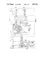
- FIG. 1is a schematic representation of dialysate preparation and supply apparatus according to the invention.
- FIG. 2is a block diagram of digital control and monitor processors used to control the FIG. 1 apparatus according to the invention.
- dialysate preparation and supply apparatus 10including dialysate preparation subsystem 12, ultrafiltration control (UFC) subsystem 14, and blood-handling subsystem 16.
- Dialysateis supplied from UFC subsystem 14 to dialysate inlet 18 of dialyzer 20, having a pleated membrane therein defining dialysate channels on one side of it and blood channels on its other side.
- Spent dialysateis returned to UFC subsystem 14 from dialysate outlet 22 of dialyzer 20.
- Bloodis supplied to blood inlet 24 of dialyzer 20 from blood-handling subsystem 16 and is returned to subsystem 16 from blood outlet 26 of dialyzer 20.
- a patientis connected to blood supply line 28 and blood return line 30 of blood handling subsystem 16.
- Dialysate preparation subsystem 12receives tap water at inlet 28 and discharges spent dialysate at drain 30. Downstream from inlet 28 along main flow line 29 are on/off solenoid valve 30, temperature sensor 32, heater/deaeration chamber 34, deaeration gear pump 36, junction 38 (at which concentrate is added), mixing chamber 40, conductivity sensor 42, and pH sensor 44.
- Heater/deaeration chambr 34includes 800-watt immersion heater 46, temperature sensor 48 (sensing temperature of water leaving the heater), and level sensor 50.
- concentrate line 52Connected to junction 38 is concentrate line 52, including concentrate pump 54 (a constant-stroke-volume diaphragm pump) and fitting 56 on its remote end for connecting to either fitting 58 of dialysate concentrate jug 60 or fitting 62, connected to bleach jug 64 via a line including flow sensing switch 66.
- Air separation lines from heater/deaeration chamber 34 and mixing chamber 40are connected to vacuum/waste line 67 leading to vacuum/waste gear pump 69.
- UFC subsystem 14includes, continuing along main flow line 29, balance chambers 68, 70, connected in parallel and having fresh dialysate chambers 72, 74 on the right-hand sides and spent dialysate chambers 76, 78 on the left-hand sides.
- Hall effect sensors 80sense the positions of magnets carried by the diaphragms 82 in balance chambers 68, 70. Downstream of the fresh dialysate chambers of balance chambers 68, 70 are junction 84 (to ultrafiltration pump 86, a constant-stroke-volume diaphragm pump), final temperature sensor 88, final conductivity sensor 90, two-position bypass valve 92, and dialysate inlet pressure sensor 94, just upstream of dialysate inlet 18.
- dialysate outlet pressure sensor 96Downstream of dialyzer 20 in the UFC subsystem are dialysate outlet pressure sensor 96, air separator 98 (including level sensor 100 therein), gear flow pump 102, and blood leak detector 104, just upstream of spent dialysate chambers 76, 78 of balance chambers 68, 70.
- the outlets of spent dialysate chambers 76, 78are connected to vacuum/waste line 67 leading to vacuum/waste pump 69, as are the waste line from ultrafiltration pump 86 and air separation line 108 from air separator 98.
- Balance chambers 68, 70have solenoid valves connected to the inlets and outlets to alternately fill a fresh dialysate chamber while the spent dialysate chamber of the same balance chamber is being emptied and to fill the spent dialysate chamber of the other balance chamber with spent dialysate while its fresh dialysate chamber is being emptied, and vice versa, as is known in the art.
- dialysate flow to and from dialyzer 20is balanced, and the precise amount of ultrafiltrate (liquid passing through the membrane in dialyzer 20 from blood to dialysate) is removed, by removing the desired amount using pump 86.
- Two-position bypass valve 92includes the flow path shown at the right of the dashed line, connecting main flow line 29 to the dialyzer, and the flow path shown at the left of the dashed line, bypassing dialyzer 20.
- Blood-handling subsystem 16includes arterial pressure sensor 110, peristaltic blood pump 112, and heparin pump 114 on blood supply line 28 from the patient to blood inlet 24. It also includes venous pressure sensor 116, air bubble detector 118, and solenoid clamping valve 120 on blood return line 30 from blood outlet 26 to the patient.
- FIG. 2there is shown the block diagram for the control and monitoring system of apparatus 10.
- Each hydraulic subsystem 12, 14, 16has a corresponding digital control processor 122, 124, 126 and a corresponding digital monitor processor 128, 130, 132, respectively.
- Each control processor 122, 124, 126is connected to master controller 134, connected to receive operator input from data entry keyboard 136.
- Each digital monitor 128, 130, 132is similarly connected to a master monitor processor 140, connected to communicate information to the operator via CRT display 138.
- the blood handling systemalso has its own data entry keyboard 142 and LED display 144 connected as shown in FIG. 2. As is also shown in FIG.
- control and monitor processorsare connected to receive fluid condition signals from the indicated fluid condition sensors, and the control processors are connected to provide control signals to the indicated control mechanisms.
- the fluid condition sensorsare connected to both the control processor and the monitor processor in a subsystem.
- the monitor processorscan remove the power from control mechanisms.
- the digital control and monitor processorsare programmed to carry out the control and monitoring functions described below.
- dialysateis continuously prepared in dialysate preparation subsystem 12 and supplied to and removed from the dialysate passages in dialyzer 20 at controlled flow rates by UFC subsystem 14, and blood is continuously supplied to and removed from the blood passages of dialyzer 20.
- the control of fluid conditions by each subsystemwill be discussed first, and this will be followed by discussion of safety condition monitoring.
- the fluid control mechanismsi.e., the pumps, valves, etc.
- control loopscarried out by the digital control processors of the respective hydraulic subsystems.
- dialysate preparation subsystem 12water enters inlet 28, is heated and deaerated in chamber 34, and receives dialysate concentrate at junction 38.
- the mixed dialysatethen flows to UFC subsystem 14.
- Heater 46is switched on and off based upon the inlet and outlet temperatures sensed by temperature sensors 32, 48.
- Valve 30is switched on and off in a six-second on/off duty cycle based upon the level of liquid sensed by level sensor 50.
- Concentrate pump 54is controlled by the conductivity sensed by conductivity sensor 42.
- Deaeration pump 36 and vacuum/waste pump 69are also controlled by control processor 122 to achieve desired flow rates, which can be entered into master controller 134 by the operator.
- dialysateflows alternately into and out of fresh dialysate chambers 72, 74 (one being filled while the other is emptied), flows through the dialysate passages of dialyzer 20, flows alternately into and out of spent dialysate chambers 76, 78 (one being filled while the other is emptied), and flows to vacuum/waste line 67.
- the balance chamber valves(not shown) at the inlets and outlets of balance chambers 68, 70 are switched open or shut in response to signals from diaphragm position sensors 80 indicating the end of travel of the diaphragms.
- Ultrafiltration pump 86is controlled by control processor 124 to pump liquid out at a rate equal to desired ultrafiltration entered into the master control processor 134 by the operator.
- Flow pump 102is similarly controlled based upon desired flow rate entered into master control processor 134.
- bloodis pumped from the patient by blood pump 112 at a desired flow rate, and heparin is pumped by heparin pump 114 at a desired flow rate, both under the control of blood handling control processor 126, based upon desired flow rates entered into keyboard 136 and keyboard 142, respectively, and by the operator.
- Monitor processors 128, 130, 132simultaneously monitor the conditions sensed by their respective sensors to verify that safety limits are met. If not, audible and visual alarms are given (even if not specifically mentioned below), and various precautionary measures are typically taken (as indicated below) to avoid harming the patient.
- bleach flow switch 66is used to verify that apparatus 10 is in a cleaning or disinfecting mode when flow switch 66 senses flow through it, to guarantee that bleach will not be pumped into the system when it is connected to a patient in the dialysis mode. If switch 66 senses flow when in the dialysis mode, or if pH sensor probe 44 senses that the pH is not within safe limits corresponding to pH associated with desired dialysate composition, dialysate preparation monitor 128 communicates these conditions via master monitor processor 140 to UF monitor processor 130, which then pulls power to UF pump 86 and flow pmp 102 and activates bypass valve 92, bypassing flow around dialyzer 20.
- final temperature sensor 88has a maximum temperature associated with it, and final conductivity sensor 90 has upper and lower conductivity limits associated with it. If either condition is violated, bypass valve 92 is activated. If blood leak detector 104 senses the presence of blood, this condition is communicated via ultrafiltration monitor processor 130 to master monitor processor 140, which tells blood handling monitor processor 132 to turn off blood pump 112 and communicates the condition via master control processor 134 to UF control processor 124, which operates to bring transmembrane pressure to zero. A transmembrane pressure that is too high, sensed by signals from both UF monitor processor 130 and blood handling monitor processor 132, triggers a similar response.
- a TMP that is too highindicates that the operator is trying to pull too much ultrafiltrate (in which event he can lower the ultrafiltration rate) or that the membrane is clogged (in which event use of the clogged dialyzer must be discontinued).
- One possible response to a detected blood leak conditionis increasing the triggering value of the blood leak detector.
- Level sensor 100will shut off flow pump 102 if the level in it gets so low that pump 102 could begin to suck air through it.
- Blood pressure sensors 110, 116measure the pressure in the blood supply and return lines. If pressure in one of these lines is too high, indicating a blocked condition, or too low, indicating a disconnected line, blood pump 112 is turned off by pulling the power to it, and an alarm is sounded. If air bubble detector 118 detects the presence of an air bubble, blood handling monitor processor 132 and/or blood handling control processor 126 will block blood flow to the patient, using clamp 120, and will turn off blood pump 112, by pulling the power to these control mechanisms. If air bubble detector 118 fails, the signal provided to the processors will be the same as if it had detected an air bubble, thus preventing a single failure from undermining the safety system.
Landscapes
- Health & Medical Sciences (AREA)
- Heart & Thoracic Surgery (AREA)
- Urology & Nephrology (AREA)
- Vascular Medicine (AREA)
- Hematology (AREA)
- Veterinary Medicine (AREA)
- Anesthesiology (AREA)
- Biomedical Technology (AREA)
- Engineering & Computer Science (AREA)
- Life Sciences & Earth Sciences (AREA)
- Animal Behavior & Ethology (AREA)
- General Health & Medical Sciences (AREA)
- Public Health (AREA)
- Emergency Medicine (AREA)
- Cardiology (AREA)
- External Artificial Organs (AREA)
- Separation Using Semi-Permeable Membranes (AREA)
- Pipeline Systems (AREA)
Abstract
Description
Claims (14)
Priority Applications (6)
| Application Number | Priority Date | Filing Date | Title |
|---|---|---|---|
| US07/925,305US4897184A (en) | 1986-10-31 | 1986-10-31 | Fluid flow apparatus control and monitoring |
| CA000550417ACA1323312C (en) | 1986-10-30 | 1987-10-28 | Fluid flow apparatus control and monitoring |
| DE3736712ADE3736712C2 (en) | 1986-10-31 | 1987-10-29 | Dialysate preparation and supply device |
| JP62274606AJPH0622608B2 (en) | 1986-10-31 | 1987-10-29 | Equipment for manufacturing and supplying dialysate |
| FR878715066AFR2605897B1 (en) | 1986-10-31 | 1987-10-30 | CONTROL AND MONITORING OF A FLUID TRAVED APPARATUS |
| GB8725433AGB2196756B (en) | 1986-10-31 | 1987-10-30 | Dialysate preparation and supply apparatus |
Applications Claiming Priority (1)
| Application Number | Priority Date | Filing Date | Title |
|---|---|---|---|
| US07/925,305US4897184A (en) | 1986-10-31 | 1986-10-31 | Fluid flow apparatus control and monitoring |
Publications (1)
| Publication Number | Publication Date |
|---|---|
| US4897184Atrue US4897184A (en) | 1990-01-30 |
Family
ID=25451534
Family Applications (1)
| Application Number | Title | Priority Date | Filing Date |
|---|---|---|---|
| US07/925,305Expired - LifetimeUS4897184A (en) | 1986-10-30 | 1986-10-31 | Fluid flow apparatus control and monitoring |
Country Status (6)
| Country | Link |
|---|---|
| US (1) | US4897184A (en) |
| JP (1) | JPH0622608B2 (en) |
| CA (1) | CA1323312C (en) |
| DE (1) | DE3736712C2 (en) |
| FR (1) | FR2605897B1 (en) |
| GB (1) | GB2196756B (en) |
Cited By (57)
| Publication number | Priority date | Publication date | Assignee | Title |
|---|---|---|---|---|
| US5112492A (en)* | 1990-12-11 | 1992-05-12 | Biotage Inc. | Automated bubble trap |
| US5230702A (en)* | 1991-01-16 | 1993-07-27 | Paradigm Biotechnologies Partnership | Hemodialysis method |
| US5242586A (en)* | 1990-12-17 | 1993-09-07 | Biotage Inc. | Column protection system for liquid chromatography system |
| US5344392A (en)* | 1990-09-28 | 1994-09-06 | Baxter International Inc. | Method and apparatus for preparation of solutions from concentrates |
| US5399157A (en)* | 1992-07-06 | 1995-03-21 | Hospal Industrie | Method for checking the operation of sensors situated in a dialysis liquid circuit |
| US5676644A (en)* | 1995-06-07 | 1997-10-14 | Cobe Laboratories, Inc. | Extracorporeal blood processing methods and apparatus |
| US5744031A (en)* | 1991-09-10 | 1998-04-28 | Hospal Industrie | Artificial kidney provided with means for determining characteristics of blood |
| US5788846A (en)* | 1993-03-05 | 1998-08-04 | Gambro Ab | Method of measuring the effect of a dialysis treatment |
| US5795317A (en)* | 1995-06-07 | 1998-08-18 | Cobe Laboratories, Inc. | Extracorporeal blood processing methods and apparatus |
| US5824213A (en)* | 1994-09-07 | 1998-10-20 | Medisystems Technology Corporation | Separable hemodialysis system |
| WO2000033904A1 (en)* | 1998-12-08 | 2000-06-15 | Instrumentarum Corporation | Arrangement in connection with feedback control system |
| US6080321A (en)* | 1996-09-06 | 2000-06-27 | Fresenius Medical Care Deutschland Gmbh | Dialysis machine for the removal of toxic substances from the blood with agents for the decalcification of a dialysis liquid circulation as well as process for determining the degree of calcification of a dialysis machine |
| US6200287B1 (en) | 1997-09-05 | 2001-03-13 | Gambro, Inc. | Extracorporeal blood processing methods and apparatus |
| US6210591B1 (en) | 1994-09-16 | 2001-04-03 | Transonic Systems, Inc. | Method to measure blood flow rate in hemodialysis shunts |
| EP1121951A1 (en)* | 2000-02-01 | 2001-08-08 | Uvo M. Prof. Hölscher Ph. D. | Regulating Circuit - System for therapy of a patient |
| US6324845B1 (en) | 2000-06-23 | 2001-12-04 | Delphi Technologies, Inc. | Self contained, supplemental vacuum assist unit for vehicle brake booster |
| WO2001056631A3 (en)* | 2000-02-01 | 2002-04-04 | Uvo Hoelscher | Safety concept for a control loop for dynamically dosing medicaments |
| US6444435B1 (en) | 2000-11-30 | 2002-09-03 | Serim Research Corporation | Test strip for determining dialysate composition |
| US6561997B1 (en)* | 1999-04-23 | 2003-05-13 | The Regents Of The University Of Michigan | Extracorporeal fluid circuit and related methods |
| US20030094736A1 (en)* | 1996-05-03 | 2003-05-22 | Chuan Qin | Method of surface modifying a medical tubing |
| WO2003080159A1 (en)* | 2002-03-27 | 2003-10-02 | Novo Nordisk A/S | A safety system for an electrically driven medical delivery device and a computer-readable medium |
| US20030231116A1 (en)* | 2002-03-27 | 2003-12-18 | Jespersen Soren Kragh | Safety system for an electrically driven medical delivery device and a computer-readable medium |
| US6730055B2 (en) | 2000-03-09 | 2004-05-04 | Gambro Inc. | Extracorporeal blood processing methods and apparatus |
| US20040129616A1 (en)* | 2002-11-14 | 2004-07-08 | Nikkiso Co. Ltd. | Blood purification device |
| US6868739B1 (en) | 1999-10-19 | 2005-03-22 | Transonic Systems, Inc. | Method and apparatus to measure blood flow by an introduced volume change |
| US20050061740A1 (en)* | 2001-10-02 | 2005-03-24 | Anders Felding | Method of controlling a dialysis apparatus |
| US20050178732A1 (en)* | 1994-09-16 | 2005-08-18 | Transonic Systems, Inc. | Measurement of a blood flow rate in hemodialysis shunts |
| US20080097272A1 (en)* | 2005-01-07 | 2008-04-24 | Pia Daniel | Device and Method for Detecting Complications During an Extracorporeal Blood Treatment |
| US20090124963A1 (en)* | 2007-11-09 | 2009-05-14 | Baxter International Inc. | Balanced flow dialysis machine |
| US20110005986A1 (en)* | 2003-11-05 | 2011-01-13 | Baxter International Inc. | Dialysis system with cassette based balance chambers and volumetric pumps |
| US20120197174A1 (en)* | 2004-04-27 | 2012-08-02 | Vital Therapies, Inc. | Metabolic Detoxification System and Method |
| US20120279910A1 (en)* | 2009-06-15 | 2012-11-08 | Mark Wallace | Dialysis Machine |
| US20150027951A1 (en)* | 2012-01-26 | 2015-01-29 | Quanta Fluid Solutions Ltd. | Dialysis Machine |
| WO2015063267A3 (en)* | 2013-10-31 | 2015-07-23 | Fresenius Medical Care Deutschland Gmbh | Blood treatment device having increased patient safety and method |
| US9925320B2 (en) | 2007-10-24 | 2018-03-27 | Baxter International Inc. | Renal therapy machine and system including a priming sequence |
| CN112370593A (en)* | 2015-02-27 | 2021-02-19 | 迈奎特心肺有限公司 | Fluid flow measurement and bubble detection device |
| CN115434392A (en)* | 2022-11-07 | 2022-12-06 | 中国建筑西南设计研究院有限公司 | Intelligent monitoring system and monitoring method for water pump house |
| US11571499B2 (en) | 2015-12-30 | 2023-02-07 | Quanta Dialysis Technologies Ltd. | Dialysis machine |
| US11583618B2 (en) | 2014-06-02 | 2023-02-21 | Quanta Dialysis Technologies Limited | Method of heat sanitization of a haemodialysis water circuit using a calculated dose |
| US11660382B2 (en) | 2016-12-23 | 2023-05-30 | Quanta Dialysis Technologies Limited | Valve leak detection system |
| USRE49881E1 (en) | 2013-03-28 | 2024-03-26 | Quanta Fluid Solutions Ltd. | Re-use of a hemodialysis cartridge |
| US11964086B2 (en) | 2010-07-07 | 2024-04-23 | Deka Products Limited Partnership | Medical treatment system and methods using a plurality of fluid lines |
| USRE50004E1 (en) | 2013-08-14 | 2024-06-11 | Quanta Dialysis Technologies Ltd. | Dual haemodialysis and haemodiafiltration blood treatment device |
| US12005169B2 (en) | 2007-02-27 | 2024-06-11 | Deka Products Limited Partnership | Modular assembly for a portable hemodialysis system |
| US12011528B2 (en) | 2017-02-02 | 2024-06-18 | Quanta Dialysis Technologies Ltd. | Phased convective operation |
| US12059516B2 (en) | 2007-02-27 | 2024-08-13 | Deka Products Limited Partnership | Blood circuit assembly for a hemodialysis system |
| US12064540B2 (en) | 2007-02-27 | 2024-08-20 | Deka Products Limited Partnership | Hemodialysis systems and methods |
| US12066017B2 (en) | 2007-02-27 | 2024-08-20 | Deka Products Limited Partnership | Pumping cassette |
| US12163513B2 (en) | 2016-02-10 | 2024-12-10 | Quanta Dialysis Technologies Ltd. | Membrane pump usage condition detection |
| US12171922B2 (en) | 2008-08-27 | 2024-12-24 | Deka Products Limited Partnership | Blood treatment systems and methods |
| US12194213B2 (en) | 2011-11-04 | 2025-01-14 | Deka Products Limited Partnership | Medical treatment system and methods using a plurality of fluid lines |
| US12220507B2 (en) | 2011-05-24 | 2025-02-11 | Deka Products Limited Partnership | Blood treatment systems and methods |
| US12251504B2 (en) | 2017-06-30 | 2025-03-18 | Quanta Dialysis Technologies Ltd. | Dialysis systems, devices and methods |
| USD1070090S1 (en) | 2017-09-28 | 2025-04-08 | Quanta Dialysis Technologies Ltd. | Dialysis machine |
| US12303631B2 (en) | 2011-11-04 | 2025-05-20 | Deka Products Limited Partnership | Medical treatment system and methods using a plurality of fluid lines |
| US12357738B2 (en) | 2019-05-31 | 2025-07-15 | Quanta Dialysis Technologies Limited | Source container connector |
| US12397097B2 (en) | 2011-05-24 | 2025-08-26 | Deka Products Limited Partnership | Systems and methods for detecting vascular access disconnection |
Families Citing this family (29)
| Publication number | Priority date | Publication date | Assignee | Title |
|---|---|---|---|---|
| US5229931A (en)* | 1988-09-21 | 1993-07-20 | Honda Giken Kogyo Kabushiki Kaisha | Nut runner control system and method of monitoring nut runners |
| CA1332970C (en)* | 1988-09-21 | 1994-11-08 | Akira Takeshima | Nut runner control system and method of monitoring nut runners |
| DE3909967A1 (en)* | 1989-03-25 | 1990-09-27 | Fresenius Ag | HAEMODIALYSIS DEVICE WITH AUTOMATIC ADJUSTMENT OF THE DIALYSIS FLUID FLOW |
| JPH07136250A (en)* | 1993-06-24 | 1995-05-30 | Althin Medical Inc | Operating method of hemodialyzing machine, programming method of time change parameter, operation method of dialyzing machine, ren dialyzing machine, and hemodialyzing machine |
| DE19849787C1 (en)* | 1998-10-28 | 2000-02-24 | Fresenius Medical Care De Gmbh | Dialysis machine includes distributed operational and auxiliary computers with bus interconnections, sensors and actuators in high-integrity redundant architecture safeguarding life-critical systems |
| BA99493A (en) | 1999-10-06 | 2000-11-06 | Mehmed Camo | Training ground for football school football players |
| CA2431431C (en)* | 2000-12-20 | 2010-03-16 | Nephros, Inc. | Multistage hemodiafiltration/hemofiltration method and apparatus |
| DE10142516B4 (en) | 2001-08-30 | 2005-04-14 | Fresenius Medical Care Deutschland Gmbh | Medical device with automated data update |
| WO2003086509A1 (en) | 2002-04-11 | 2003-10-23 | Deka Products Limited Partnership | System and method for delivering a target volume of fluid |
| DE10218894A1 (en)* | 2002-04-26 | 2003-11-13 | Storz Endoskop Prod Gmbh | Device for monitoring medical devices |
| US7744553B2 (en)† | 2003-12-16 | 2010-06-29 | Baxter International Inc. | Medical fluid therapy flow control systems and methods |
| JP4742549B2 (en)* | 2004-09-17 | 2011-08-10 | ニプロ株式会社 | Blood purification equipment |
| US10537671B2 (en) | 2006-04-14 | 2020-01-21 | Deka Products Limited Partnership | Automated control mechanisms in a hemodialysis apparatus |
| US8409441B2 (en) | 2007-02-27 | 2013-04-02 | Deka Products Limited Partnership | Blood treatment systems and methods |
| US10463774B2 (en) | 2007-02-27 | 2019-11-05 | Deka Products Limited Partnership | Control systems and methods for blood or fluid handling medical devices |
| US8042563B2 (en) | 2007-02-27 | 2011-10-25 | Deka Products Limited Partnership | Cassette system integrated apparatus |
| US8491184B2 (en) | 2007-02-27 | 2013-07-23 | Deka Products Limited Partnership | Sensor apparatus systems, devices and methods |
| US8393690B2 (en) | 2007-02-27 | 2013-03-12 | Deka Products Limited Partnership | Enclosure for a portable hemodialysis system |
| US8287724B2 (en)* | 2007-07-05 | 2012-10-16 | Baxter International Inc. | Dialysis fluid measurement systems using conductive contacts |
| US11833281B2 (en) | 2008-01-23 | 2023-12-05 | Deka Products Limited Partnership | Pump cassette and methods for use in medical treatment system using a plurality of fluid lines |
| US10201647B2 (en) | 2008-01-23 | 2019-02-12 | Deka Products Limited Partnership | Medical treatment system and methods using a plurality of fluid lines |
| JP5595930B2 (en) | 2008-01-23 | 2014-09-24 | デカ・プロダクツ・リミテッド・パートナーシップ | Disposable components for fluid line automatic connection systems |
| CN104841030B (en) | 2009-10-30 | 2017-10-31 | 德卡产品有限公司 | For the apparatus and method for the disconnection for detecting intravascular access device |
| EP3205362B1 (en) | 2011-05-24 | 2022-07-06 | DEKA Products Limited Partnership | Hemodialysis system |
| US12026271B2 (en) | 2014-05-27 | 2024-07-02 | Deka Products Limited Partnership | Control systems and methods for blood or fluid handling medical devices |
| US11737821B2 (en)* | 2019-07-30 | 2023-08-29 | Biosense Webster (Israel) Ltd. | Bubble detector on proximal end of catheter with fail-safe mechanism |
| DE102019130294A1 (en)* | 2019-11-11 | 2021-05-12 | Fresenius Medical Care Deutschland Gmbh | Dialysis machine for carrying out a push-pull dialysis treatment |
| DE102020135023A1 (en) | 2020-12-29 | 2022-06-30 | Fresenius Medical Care Deutschland Gmbh | Device for the combined display of data relating to blood treatment machines and water treatment plants |
| DE102021129003A1 (en)* | 2021-11-08 | 2023-05-11 | B.Braun Avitum Ag | Modular blood treatment device |
Citations (4)
| Publication number | Priority date | Publication date | Assignee | Title |
|---|---|---|---|---|
| US3946731A (en)* | 1971-01-20 | 1976-03-30 | Lichtenstein Eric Stefan | Apparatus for extracorporeal treatment of blood |
| US4153554A (en)* | 1977-02-22 | 1979-05-08 | American Micro-Bionics Corp. | Apparatus for use in artificial kidney system |
| US4371385A (en)* | 1981-04-28 | 1983-02-01 | Cobe Laboratories, Inc. | Deaerating liquid |
| US4370983A (en)* | 1971-01-20 | 1983-02-01 | Lichtenstein Eric Stefan | Computer-control medical care system |
Family Cites Families (16)
| Publication number | Priority date | Publication date | Assignee | Title |
|---|---|---|---|---|
| GB1492386A (en)* | 1974-07-31 | 1977-11-16 | Lichtenstein E | Automated apparatus for monitoring of physiological parameters and control of fluid therapy including extracorporeal circulation of blood |
| GB1560660A (en)* | 1975-12-30 | 1980-02-06 | Rhone Poulenc Ind | Dialyser system and control unit therefor |
| CS200909B1 (en)* | 1977-12-23 | 1980-10-31 | Petr Slovak | Haemodlialysation device |
| DE2948784A1 (en)* | 1979-03-08 | 1980-09-18 | Sundstrand Corp | TESTING SYSTEM FOR A DYNAMIC MACHINE |
| JPS565664A (en)* | 1979-06-28 | 1981-01-21 | Shiyunji Motomura | Smalllsized blood dialyzer |
| DE3151634A1 (en)* | 1980-12-27 | 1982-07-08 | Canon K.K., Tokyo | "IMAGE GENERATION DEVICE" |
| US4424559A (en)* | 1981-02-27 | 1984-01-03 | New Brunswick Scientific Co., Inc. | Modular instrumentation for monitoring and control of biochemical processes |
| JPS5810246A (en)* | 1981-07-13 | 1983-01-20 | Nissan Motor Co Ltd | Vehicle digital control device |
| JPS592339U (en)* | 1982-06-30 | 1984-01-09 | 横河電機株式会社 | artificial dialysis machine |
| GB2125577B (en)* | 1982-08-16 | 1986-09-24 | Nissan Motor | Self monitoring system |
| US4477342A (en)* | 1982-08-31 | 1984-10-16 | Becton, Dickinson And Company | Apparatus and method for controlling ultrafiltration during hemodialysis |
| JPS5941427U (en)* | 1982-09-08 | 1984-03-16 | 株式会社三陽電機製作所 | Operating status display device |
| JPS5941428U (en)* | 1982-09-08 | 1984-03-16 | 三菱電機株式会社 | Artificial dialysis monitor device |
| JPS5964137U (en)* | 1982-10-20 | 1984-04-27 | 株式会社三陽電機製作所 | Artificial kidney device for dialysis |
| DE3313421C2 (en)* | 1983-04-13 | 1985-08-08 | Fresenius AG, 6380 Bad Homburg | Device for regulating the ultrafiltration rate in devices for extracorporeal cleaning of blood |
| DE3401761C2 (en)* | 1984-01-19 | 1987-04-16 | Fresenius AG, 6380 Bad Homburg | Control device |
- 1986
- 1986-10-31USUS07/925,305patent/US4897184A/ennot_activeExpired - Lifetime
- 1987
- 1987-10-28CACA000550417Apatent/CA1323312C/ennot_activeExpired - Lifetime
- 1987-10-29DEDE3736712Apatent/DE3736712C2/ennot_activeExpired - Lifetime
- 1987-10-29JPJP62274606Apatent/JPH0622608B2/ennot_activeExpired - Lifetime
- 1987-10-30FRFR878715066Apatent/FR2605897B1/ennot_activeExpired - Lifetime
- 1987-10-30GBGB8725433Apatent/GB2196756B/ennot_activeExpired - Lifetime
Patent Citations (4)
| Publication number | Priority date | Publication date | Assignee | Title |
|---|---|---|---|---|
| US3946731A (en)* | 1971-01-20 | 1976-03-30 | Lichtenstein Eric Stefan | Apparatus for extracorporeal treatment of blood |
| US4370983A (en)* | 1971-01-20 | 1983-02-01 | Lichtenstein Eric Stefan | Computer-control medical care system |
| US4153554A (en)* | 1977-02-22 | 1979-05-08 | American Micro-Bionics Corp. | Apparatus for use in artificial kidney system |
| US4371385A (en)* | 1981-04-28 | 1983-02-01 | Cobe Laboratories, Inc. | Deaerating liquid |
Cited By (102)
| Publication number | Priority date | Publication date | Assignee | Title |
|---|---|---|---|---|
| US5344392A (en)* | 1990-09-28 | 1994-09-06 | Baxter International Inc. | Method and apparatus for preparation of solutions from concentrates |
| US5112492A (en)* | 1990-12-11 | 1992-05-12 | Biotage Inc. | Automated bubble trap |
| US5242586A (en)* | 1990-12-17 | 1993-09-07 | Biotage Inc. | Column protection system for liquid chromatography system |
| US5230702A (en)* | 1991-01-16 | 1993-07-27 | Paradigm Biotechnologies Partnership | Hemodialysis method |
| US5744031A (en)* | 1991-09-10 | 1998-04-28 | Hospal Industrie | Artificial kidney provided with means for determining characteristics of blood |
| US5399157A (en)* | 1992-07-06 | 1995-03-21 | Hospal Industrie | Method for checking the operation of sensors situated in a dialysis liquid circuit |
| US5788846A (en)* | 1993-03-05 | 1998-08-04 | Gambro Ab | Method of measuring the effect of a dialysis treatment |
| US5824213A (en)* | 1994-09-07 | 1998-10-20 | Medisystems Technology Corporation | Separable hemodialysis system |
| US6210591B1 (en) | 1994-09-16 | 2001-04-03 | Transonic Systems, Inc. | Method to measure blood flow rate in hemodialysis shunts |
| US7473371B2 (en) | 1994-09-16 | 2009-01-06 | Transonic Systems, Inc. | Measurement of a blood flow rate in hemodialysis shunts |
| US20050178732A1 (en)* | 1994-09-16 | 2005-08-18 | Transonic Systems, Inc. | Measurement of a blood flow rate in hemodialysis shunts |
| US7297280B2 (en) | 1994-09-16 | 2007-11-20 | Transonic Systems, Inc. | Method and apparatus to measure blood flow in hemodialysis shunts |
| US5795317A (en)* | 1995-06-07 | 1998-08-18 | Cobe Laboratories, Inc. | Extracorporeal blood processing methods and apparatus |
| US6234989B1 (en) | 1995-06-07 | 2001-05-22 | Gambro, Inc. | Extracorporeal blood processing methods and apparatus |
| US5676644A (en)* | 1995-06-07 | 1997-10-14 | Cobe Laboratories, Inc. | Extracorporeal blood processing methods and apparatus |
| US5921950A (en)* | 1995-06-07 | 1999-07-13 | Cobe Laboratories, Inc. | Extracorporeal blood processing methods and apparatus |
| US6361518B1 (en) | 1995-06-07 | 2002-03-26 | Gambro Inc. | Extracorporeal blood processing methods and apparatus |
| US6409696B1 (en) | 1995-06-07 | 2002-06-25 | Gambro, Inc. | Extracorporeal blood processing methods and apparatus |
| US5919154A (en)* | 1995-06-07 | 1999-07-06 | Cobe Laboratories, Inc. | Extracorporeal blood processing methods and apparatus |
| US20030094736A1 (en)* | 1996-05-03 | 2003-05-22 | Chuan Qin | Method of surface modifying a medical tubing |
| US6080321A (en)* | 1996-09-06 | 2000-06-27 | Fresenius Medical Care Deutschland Gmbh | Dialysis machine for the removal of toxic substances from the blood with agents for the decalcification of a dialysis liquid circulation as well as process for determining the degree of calcification of a dialysis machine |
| US6200287B1 (en) | 1997-09-05 | 2001-03-13 | Gambro, Inc. | Extracorporeal blood processing methods and apparatus |
| US6773413B2 (en) | 1997-09-05 | 2004-08-10 | Gamero Inc | Extracorporeal blood processing methods and apparatus |
| WO2000033904A1 (en)* | 1998-12-08 | 2000-06-15 | Instrumentarum Corporation | Arrangement in connection with feedback control system |
| US7290544B1 (en) | 1998-12-08 | 2007-11-06 | Ge Healthcare Finland Oy | Arrangement in connection with feedback control system |
| US6561997B1 (en)* | 1999-04-23 | 2003-05-13 | The Regents Of The University Of Michigan | Extracorporeal fluid circuit and related methods |
| US6913588B2 (en) | 1999-04-23 | 2005-07-05 | Nephros Therapeutics, Inc. | Extracorporeal fluid circuit and related methods |
| US7121150B2 (en) | 1999-10-19 | 2006-10-17 | Transonic Systems, Inc. | Method and apparatus to determine an initial flow rate in a conduit |
| US6868739B1 (en) | 1999-10-19 | 2005-03-22 | Transonic Systems, Inc. | Method and apparatus to measure blood flow by an introduced volume change |
| US20030171733A1 (en)* | 2000-02-01 | 2003-09-11 | Uvo Hoelscher | Safety concept for a control loop for dynamically dosing medicaments |
| WO2001056631A3 (en)* | 2000-02-01 | 2002-04-04 | Uvo Hoelscher | Safety concept for a control loop for dynamically dosing medicaments |
| EP1121951A1 (en)* | 2000-02-01 | 2001-08-08 | Uvo M. Prof. Hölscher Ph. D. | Regulating Circuit - System for therapy of a patient |
| US20040230152A1 (en)* | 2000-03-09 | 2004-11-18 | Gambro, Inc. | Extra-corporeal Blood Processing Method and Apparatus Based on Donor Characteristics |
| US7354415B2 (en) | 2000-03-09 | 2008-04-08 | Gambro Bct, Inc. | Extra-corporeal blood processing method and apparatus based on donor characteristics |
| US20040249332A1 (en)* | 2000-03-09 | 2004-12-09 | Gambro, Inc. | Extra-corporeal Dual Stage Blood Processing Method and Apparatus |
| US6730055B2 (en) | 2000-03-09 | 2004-05-04 | Gambro Inc. | Extracorporeal blood processing methods and apparatus |
| US6945948B2 (en) | 2000-03-09 | 2005-09-20 | Gambro, Inc. | Extra-corporeal dual stage blood processing method and apparatus |
| US6324845B1 (en) | 2000-06-23 | 2001-12-04 | Delphi Technologies, Inc. | Self contained, supplemental vacuum assist unit for vehicle brake booster |
| US20030044873A1 (en)* | 2000-11-30 | 2003-03-06 | Christner James E. | Test strip for determining dialysate composition |
| US6986999B2 (en) | 2000-11-30 | 2006-01-17 | Serim Research Corporation | Test strip for determining dialysate composition |
| US7015009B2 (en) | 2000-11-30 | 2006-03-21 | Serim Research Corporation | Test strip for determining dialysate composition |
| US20030044874A1 (en)* | 2000-11-30 | 2003-03-06 | Christner James E. | Test strip for determining dialysate composition |
| US6444435B1 (en) | 2000-11-30 | 2002-09-03 | Serim Research Corporation | Test strip for determining dialysate composition |
| US20050061740A1 (en)* | 2001-10-02 | 2005-03-24 | Anders Felding | Method of controlling a dialysis apparatus |
| US7494590B2 (en)* | 2001-10-02 | 2009-02-24 | Gambro Lundia Ab | Method of controlling a dialysis apparatus |
| US7597679B2 (en) | 2002-03-27 | 2009-10-06 | Novo Nordisk A/S | Safety system for an electrically driven medical delivery device and a computer-readable medium |
| WO2003080159A1 (en)* | 2002-03-27 | 2003-10-02 | Novo Nordisk A/S | A safety system for an electrically driven medical delivery device and a computer-readable medium |
| CN100435868C (en)* | 2002-03-27 | 2008-11-26 | 诺沃挪第克公司 | A safety system for an electrically driven medical delivery device and a computer-readable medium |
| US20030231116A1 (en)* | 2002-03-27 | 2003-12-18 | Jespersen Soren Kragh | Safety system for an electrically driven medical delivery device and a computer-readable medium |
| US20040129616A1 (en)* | 2002-11-14 | 2004-07-08 | Nikkiso Co. Ltd. | Blood purification device |
| US7758532B2 (en)* | 2002-11-14 | 2010-07-20 | Nikkiso Co., Ltd. | Blood purification device |
| US20110005986A1 (en)* | 2003-11-05 | 2011-01-13 | Baxter International Inc. | Dialysis system with cassette based balance chambers and volumetric pumps |
| US9572919B2 (en) | 2003-11-05 | 2017-02-21 | Baxter International Inc. | Dialysis system with cassette based balance chambers and volumetric pumps |
| US9005152B2 (en) | 2003-11-05 | 2015-04-14 | Baxter International Inc. | Dialysis system with cassette based balance chambers and volumetric pumps |
| US20110005992A1 (en)* | 2003-11-05 | 2011-01-13 | Baxter International Inc. | Dialysis system with balance chamber prime and rinseback |
| US9480784B2 (en) | 2003-11-05 | 2016-11-01 | Baxter International Inc. | Dialysis system with balance chamber prime and rinseback |
| US9889243B2 (en) | 2003-11-05 | 2018-02-13 | Baxter International Inc. | Dialysis system including automatic priming |
| US9144641B2 (en) | 2003-11-05 | 2015-09-29 | Baxter International Inc. | Dialysis system with balance chamber prime and rinseback |
| US20120197174A1 (en)* | 2004-04-27 | 2012-08-02 | Vital Therapies, Inc. | Metabolic Detoxification System and Method |
| US8608953B2 (en)* | 2004-04-27 | 2013-12-17 | Vital Therapies, Inc. | Metabolic detoxification system and method |
| US7674236B2 (en)* | 2005-01-07 | 2010-03-09 | Fresenius Medical Care Deutschland Gmbh | Device and method for detecting complications during an extracorporeal blood treatment |
| US20080097272A1 (en)* | 2005-01-07 | 2008-04-24 | Pia Daniel | Device and Method for Detecting Complications During an Extracorporeal Blood Treatment |
| US12059516B2 (en) | 2007-02-27 | 2024-08-13 | Deka Products Limited Partnership | Blood circuit assembly for a hemodialysis system |
| US12005169B2 (en) | 2007-02-27 | 2024-06-11 | Deka Products Limited Partnership | Modular assembly for a portable hemodialysis system |
| US12064540B2 (en) | 2007-02-27 | 2024-08-20 | Deka Products Limited Partnership | Hemodialysis systems and methods |
| US12066017B2 (en) | 2007-02-27 | 2024-08-20 | Deka Products Limited Partnership | Pumping cassette |
| US11975129B2 (en) | 2007-10-24 | 2024-05-07 | Baxter International Inc. | Hemodialysis system including a disposable set and a dialysis instrument |
| US11291752B2 (en) | 2007-10-24 | 2022-04-05 | Baxter International Inc. | Hemodialysis system including a disposable set and a dialysis instrument |
| US10695479B2 (en) | 2007-10-24 | 2020-06-30 | Baxter International Inc. | Renal therapy machine and method including a priming sequence |
| US9925320B2 (en) | 2007-10-24 | 2018-03-27 | Baxter International Inc. | Renal therapy machine and system including a priming sequence |
| US8992463B2 (en)* | 2007-11-09 | 2015-03-31 | Baxter International Inc. | Balanced flow dialysis machine |
| AU2013260729B2 (en)* | 2007-11-09 | 2015-09-03 | Baxter Healthcare Sa | Balanced flow dialysis machine |
| US20130193073A1 (en)* | 2007-11-09 | 2013-08-01 | Baxter Healthcare S.A. | Balanced flow dialysis machine |
| US9415150B2 (en)* | 2007-11-09 | 2016-08-16 | Baxter Healthcare S.A. | Balanced flow dialysis machine |
| US11931492B2 (en) | 2007-11-09 | 2024-03-19 | Baxter International Inc. | Balanced flow dialysis machine |
| US20090124963A1 (en)* | 2007-11-09 | 2009-05-14 | Baxter International Inc. | Balanced flow dialysis machine |
| US11052180B2 (en) | 2007-11-09 | 2021-07-06 | Baxter International Inc. | Balanced flow dialysis machine |
| US12171922B2 (en) | 2008-08-27 | 2024-12-24 | Deka Products Limited Partnership | Blood treatment systems and methods |
| US20120279910A1 (en)* | 2009-06-15 | 2012-11-08 | Mark Wallace | Dialysis Machine |
| US11964086B2 (en) | 2010-07-07 | 2024-04-23 | Deka Products Limited Partnership | Medical treatment system and methods using a plurality of fluid lines |
| US12220507B2 (en) | 2011-05-24 | 2025-02-11 | Deka Products Limited Partnership | Blood treatment systems and methods |
| US12397097B2 (en) | 2011-05-24 | 2025-08-26 | Deka Products Limited Partnership | Systems and methods for detecting vascular access disconnection |
| US12194213B2 (en) | 2011-11-04 | 2025-01-14 | Deka Products Limited Partnership | Medical treatment system and methods using a plurality of fluid lines |
| US12303631B2 (en) | 2011-11-04 | 2025-05-20 | Deka Products Limited Partnership | Medical treatment system and methods using a plurality of fluid lines |
| US10960120B2 (en)* | 2012-01-26 | 2021-03-30 | Quanta Dialysis Technologies Limited | Dialysis machine |
| US20150027951A1 (en)* | 2012-01-26 | 2015-01-29 | Quanta Fluid Solutions Ltd. | Dialysis Machine |
| USRE49881E1 (en) | 2013-03-28 | 2024-03-26 | Quanta Fluid Solutions Ltd. | Re-use of a hemodialysis cartridge |
| USRE50004E1 (en) | 2013-08-14 | 2024-06-11 | Quanta Dialysis Technologies Ltd. | Dual haemodialysis and haemodiafiltration blood treatment device |
| WO2015063267A3 (en)* | 2013-10-31 | 2015-07-23 | Fresenius Medical Care Deutschland Gmbh | Blood treatment device having increased patient safety and method |
| CN105682701A (en)* | 2013-10-31 | 2016-06-15 | 弗雷塞尼斯医疗保健德国有限责任公司 | Blood treatment device having increased patient safety and method |
| CN105682701B (en)* | 2013-10-31 | 2019-08-27 | 弗雷塞尼斯医疗保健德国有限责任公司 | Blood therapy device and method for improving patient safety |
| US12161787B2 (en) | 2014-06-02 | 2024-12-10 | Quanta Dialysis Technologies Limited | Method of heat sanitization of a haemodialysis water circuit using a calculated dose |
| US11583618B2 (en) | 2014-06-02 | 2023-02-21 | Quanta Dialysis Technologies Limited | Method of heat sanitization of a haemodialysis water circuit using a calculated dose |
| CN112370593A (en)* | 2015-02-27 | 2021-02-19 | 迈奎特心肺有限公司 | Fluid flow measurement and bubble detection device |
| US11571499B2 (en) | 2015-12-30 | 2023-02-07 | Quanta Dialysis Technologies Ltd. | Dialysis machine |
| US12163513B2 (en) | 2016-02-10 | 2024-12-10 | Quanta Dialysis Technologies Ltd. | Membrane pump usage condition detection |
| US11660382B2 (en) | 2016-12-23 | 2023-05-30 | Quanta Dialysis Technologies Limited | Valve leak detection system |
| US12011528B2 (en) | 2017-02-02 | 2024-06-18 | Quanta Dialysis Technologies Ltd. | Phased convective operation |
| US12251504B2 (en) | 2017-06-30 | 2025-03-18 | Quanta Dialysis Technologies Ltd. | Dialysis systems, devices and methods |
| USD1070090S1 (en) | 2017-09-28 | 2025-04-08 | Quanta Dialysis Technologies Ltd. | Dialysis machine |
| US12357738B2 (en) | 2019-05-31 | 2025-07-15 | Quanta Dialysis Technologies Limited | Source container connector |
| CN115434392A (en)* | 2022-11-07 | 2022-12-06 | 中国建筑西南设计研究院有限公司 | Intelligent monitoring system and monitoring method for water pump house |
Also Published As
| Publication number | Publication date |
|---|---|
| FR2605897B1 (en) | 1991-11-15 |
| CA1323312C (en) | 1993-10-19 |
| FR2605897A1 (en) | 1988-05-06 |
| JPH0622608B2 (en) | 1994-03-30 |
| GB2196756B (en) | 1991-06-26 |
| JPS63127766A (en) | 1988-05-31 |
| DE3736712A1 (en) | 1988-05-11 |
| GB2196756A (en) | 1988-05-05 |
| GB8725433D0 (en) | 1987-12-02 |
| DE3736712C2 (en) | 1995-03-16 |
Similar Documents
| Publication | Publication Date | Title |
|---|---|---|
| US4897184A (en) | Fluid flow apparatus control and monitoring | |
| US5431811A (en) | Artificial kidney with device for filtering dialysis liquid | |
| EP2142235B1 (en) | Apparatus for extracorporeal blood treatment | |
| JP4101382B2 (en) | Blood processing equipment | |
| RU2298428C2 (en) | Method and the device for operation with the hemmodiafiltering receiving-withdrawing module | |
| EP0829265B1 (en) | Method for priming a circuit for multiple blood extracorporeal treatments | |
| US8182691B2 (en) | Apparatus for extracorporeal blood treatment with a device for checking a sterile filter, and method of checking a sterile filter of an extracorporeal blood treatment apparatus | |
| JPS6041972A (en) | Ultrafiltration speed controller of blood external recirculation purifying apparatus | |
| US8480609B2 (en) | Apparatus for extracorporeal blood treatment | |
| JPH0775668A (en) | Method to determine operatability of structural part in dialysis section of dialyzer for hemo-dialyzer, and device to perform said method | |
| JPS61143074A (en) | Blood dialyzer | |
| EP0951303A1 (en) | Device and method for preparation of substitution solution | |
| JPH08332222A (en) | Blood filtration apparatus with device for controlling flow rate of filtrate | |
| US20170296733A1 (en) | Method of draining a device for extracorporeal blood treatment | |
| US20110168291A1 (en) | Device for filling a filter, and method therefor | |
| CA2587059A1 (en) | Automatic reinfusing system | |
| JP6070348B2 (en) | Hemodialysis machine | |
| US20240207494A1 (en) | Method for Controlling a Blood Treatment Apparatus, and Apparatuses | |
| US4857181A (en) | Control of cleaning of dialysate preparation apparatus | |
| CN109414541B (en) | Control unit for detecting blood in a dialysate discharge line of a blood treatment device and blood treatment device | |
| JP3933512B2 (en) | Hemodialysis machine | |
| JP2510736B2 (en) | Water removal control monitoring system for dialysis equipment | |
| JPS63238868A (en) | Dialysate supply device | |
| JP7717723B2 (en) | Extracorporeal blood treatment device | |
| JPH0363065A (en) | Artificial dialyser |
Legal Events
| Date | Code | Title | Description |
|---|---|---|---|
| AS | Assignment | Owner name:COBE LABORATORIES, INC., LAKEWOOD COLORADO A COLOR Free format text:ASSIGNMENT OF ASSIGNORS INTEREST.;ASSIGNORS:SHOULDICE, DAVID R.;POWELL, DANIEL A.;BROSE, TOM L.;REEL/FRAME:004696/0414 Effective date:19870127 | |
| STCF | Information on status: patent grant | Free format text:PATENTED CASE | |
| FEPP | Fee payment procedure | Free format text:PAYOR NUMBER ASSIGNED (ORIGINAL EVENT CODE: ASPN); ENTITY STATUS OF PATENT OWNER: LARGE ENTITY | |
| FPAY | Fee payment | Year of fee payment:4 | |
| FPAY | Fee payment | Year of fee payment:8 | |
| AS | Assignment | Owner name:GAMBRO, INC., COLORADO Free format text:CHANGE OF NAME;ASSIGNOR:COBE LABORATORIES, INC.;REEL/FRAME:011190/0225 Effective date:19991221 | |
| FPAY | Fee payment | Year of fee payment:12 | |
| AS | Assignment | Owner name:CITICORP TRUSTEE COMPANY LIMITED, AS SECURITY AGEN Free format text:SECURITY AGREEMENT;ASSIGNOR:GAMBRO, INC.;REEL/FRAME:018552/0717 Effective date:20061117 | |
| AS | Assignment | Owner name:GAMBRO RENAL PRODUCTS, INC., COLORADO Free format text:ASSIGNMENT OF ASSIGNORS INTEREST;ASSIGNOR:GAMBRO, INC.;REEL/FRAME:018787/0246 Effective date:20061218 | |
| AS | Assignment | Owner name:CITICORP TRUSTEE COMPANY LIMITED, AS SECURITY AGEN Free format text:SECURITY AGREEMENT;ASSIGNOR:GAMBRO RENAL PRODUCTS, INC.;REEL/FRAME:018855/0084 Effective date:20061228 | |
| AS | Assignment | Owner name:GAMBRO, INC., COLORADO Free format text:RELEASE BY SECURED PARTY;ASSIGNOR:CITICORP TRUSTEE COMPANY LIMITED, AS SECURITY AGENT;REEL/FRAME:026209/0914 Effective date:20110413 | |
| AS | Assignment | Owner name:GAMBRO RENAL PRODUCTS, INC., COLORADO Free format text:RELEASE OF SECURITY INTEREST IN PATENTS;ASSIGNOR:CITICORP TRUSTEE COMPANY LIMITED, AS SECURITY AGENT;REEL/FRAME:027455/0318 Effective date:20111207 |