US4896777A - Lock and shock mounted device for computer disk drive - Google Patents
Lock and shock mounted device for computer disk driveDownload PDFInfo
- Publication number
- US4896777A US4896777AUS07/178,295US17829588AUS4896777AUS 4896777 AUS4896777 AUS 4896777AUS 17829588 AUS17829588 AUS 17829588AUS 4896777 AUS4896777 AUS 4896777A
- Authority
- US
- United States
- Prior art keywords
- cam
- support
- assembly
- mounting system
- locking
- Prior art date
- Legal status (The legal status is an assumption and is not a legal conclusion. Google has not performed a legal analysis and makes no representation as to the accuracy of the status listed.)
- Expired - Lifetime
Links
- 230000035939shockEffects0.000titleclaimsdescription19
- 230000003213activating effectEffects0.000claims2
- 238000013500data storageMethods0.000description4
- 238000002955isolationMethods0.000description2
- 230000003247decreasing effectEffects0.000description1
- 238000009434installationMethods0.000description1
- 238000012423maintenanceMethods0.000description1
- 238000000034methodMethods0.000description1
- 238000012986modificationMethods0.000description1
- 230000004048modificationEffects0.000description1
Images


Classifications
- G—PHYSICS
- G11—INFORMATION STORAGE
- G11B—INFORMATION STORAGE BASED ON RELATIVE MOVEMENT BETWEEN RECORD CARRIER AND TRANSDUCER
- G11B33/00—Constructional parts, details or accessories not provided for in the other groups of this subclass
- G11B33/12—Disposition of constructional parts in the apparatus, e.g. of power supply, of modules
- G11B33/121—Disposition of constructional parts in the apparatus, e.g. of power supply, of modules the apparatus comprising a single recording/reproducing device
- G11B33/123—Mounting arrangements of constructional parts onto a chassis
- G11B33/124—Mounting arrangements of constructional parts onto a chassis of the single recording/reproducing device, e.g. disk drive, onto a chassis
- G—PHYSICS
- G11—INFORMATION STORAGE
- G11B—INFORMATION STORAGE BASED ON RELATIVE MOVEMENT BETWEEN RECORD CARRIER AND TRANSDUCER
- G11B33/00—Constructional parts, details or accessories not provided for in the other groups of this subclass
- G11B33/02—Cabinets; Cases; Stands; Disposition of apparatus therein or thereon
- G11B33/08—Insulation or absorption of undesired vibrations or sounds
- H—ELECTRICITY
- H05—ELECTRIC TECHNIQUES NOT OTHERWISE PROVIDED FOR
- H05K—PRINTED CIRCUITS; CASINGS OR CONSTRUCTIONAL DETAILS OF ELECTRIC APPARATUS; MANUFACTURE OF ASSEMBLAGES OF ELECTRICAL COMPONENTS
- H05K7/00—Constructional details common to different types of electric apparatus
- H05K7/14—Mounting supporting structure in casing or on frame or rack
- H05K7/1401—Mounting supporting structure in casing or on frame or rack comprising clamping or extracting means
- H05K7/1411—Mounting supporting structure in casing or on frame or rack comprising clamping or extracting means for securing or extracting box-type drawers
Definitions
- the present inventionis directed to a mounting system for a delicate shock mounted device.
- the inventionhas particular utility for mounting a computer data storage system, and more particularly for mounting a disk drive mechanism in a computer circuit board card cage and will be described in connection with such utility although other utility is contemplated.
- a disk drive mechanismin place of standard memory boards in a computer circuit board card cage provides a convenient and cost effective method of upgrading the storage capacity of a computer.
- a disk drive mechanismhas certain relatively stringent shock mounting requirements not found in the case of card cage mounted circuit boards. Shock mounting permits a disk drive mechanism to be isolated during operation from external vibrations and shocks which are apt to be present in any building housing a computer. These shock mountings are, of necessity, relatively fragile in order to perform adequate shock isolation, and typically must be immobilized during shipment of the disk drive mechanism. Also, the shock mounting should permit removal or at least partial removal of the disk drive mechanism for maintenance and repair purposes.
- the present inventionprovides a mounting system for mounting a disk drive in the circuit board card cage of a computer. More particularly, the invention provides a shock isolation mounting device for slide mounting a disk drive mechanism in the card guide support of a computer chassis, and comprising a clamp assembly for clamping the disk drive mechanism in a first inoperative position, and a cam assembly which is displaceable with respect to the clamp assembly for moving the clamp assembly to a second operative position. There is also provided a control mechanism for selectively holding the cam assembly in its operative position and a control mechanism for controlling release of the clamp assembly so that the cam assembly can move to its inoperative position. In the inoperative position the cam assembly releases the clamp assembly so that the disk drive is free to be supported only by its shock mount.
- FIG. 1is a partially schematic diagrammatic drawing of a prior art system showing a typical card cage guide or support associated with a computer chassis and showing a printed circuit board being slid into position on the chassis;
- FIG. 2is a view similar to FIG. 1 showing a disk drive its associated support being substituted for the printed circuit board f FIG. 1, and being slid into position on the chassis in accordance with the present invention;
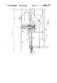
- FIG. 3is a similar to FIG. 2 showing the disk drive mounted in its working position with the disk drive being supported only by the shock mounts in accordance with the present invention
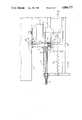
- FIG. 4is an enlarged partially sectional view showing details of one of the shock mounts and an associated clamp and cam assembly in accordance with the present invention
- FIG. 5is a view similar to FIG. 4 with the cam assembly moved to its operative position with the associated clamp assembly in clamping position with respect to the disk drive;
- FIG. 6is a view similar to FIG. 5 showing the operation of control mechanism for unlocking the cam assembly so it is free to move to its inoperative position;
- FIG. 7is a detailed partially schematic view of a portion of cam assembly control mechanism.
- FIG. 1shows a card case 10 of a computer which is arranged to receive a number of circuit boards 12 for providing data storage.
- the circuit boards 12are slide mounted on opposed card guides 14, and are electrically connected to the computer through back plane connectors 16.
- a disk drive 18shown in FIG. 2.
- the disk drive 18is carried within opposed supports 20 which are slide mounted in card guides 14, and the disk drive is mounted to supports 20 by a plurality of shock mounts 22, there preferably being two mounts at the top and two mounts at the bottom.
- a plurality of locking pins 24(shown in their retracted position) are provided for selectively holding drive 18 in an inoperative position when they engage in appropriate openings in the top and bottom of the disk drive as will be described in detail hereinafter.
- FIG. 3shows the support 20 and disk drive 18 moved to the operative position for controlling transfer of data to and from the disk drive and the associated computer.
- FIG. 4there is shown an enlarged detailed, partially sectional, view of a portion of the control mechanism for controlling the locking pins 24.
- the control mechanismcomprises the laterally displaceable cam 26 which is normally held in the position shown in FIG. 4 by means of a spring 28.
- the cam 26is arranged to bear on the bottom of locking pin 24 so that when the cam is moved to the rights as shown in FIG. 5, i.e. in the direction of Arrow A, the pin will be moved up (within support 33) into engagement with the disk drive 18.
- a locking mechanismcomprising teeth 32 associated, and movable with, cam 26 and arranged to engage ratchet teeth 34 which are carried by the support 20 by means of a cantilever arm 34.
- cam 26has been moved fully to the right and the locking pin 24 has been pushed upwardly so that the upper end 24B thereof has passed through a suitable hole 36 in the bottom of the disk drive and the flange 38 associated with the locking pin 24 is in engagement with the bottom of disk drive 18.
- cam 26can be pushed to the right by inserting a blunt tool, such as a Philips head screwdriver, through a hole (not shown) in the left hand wall of the support 20. The end of the screwdriver can then be pushed against cam 26 to move it from its inoperative position to its operative position where it becomes latched by the cooperation of the teeth 32 and 34.
- the cam 26With the teeth engaged, the cam 26 is firmly held in its operative position and the locking pins 24 firmly lock disk drive 18 in position. Generally, but not necessarily it is preferred to lock the bottom pins before locking the top pins.
- the locking pins 24may then be withdrawn from contact with the disk drive 18 so that the disk drive 18 is free to be supported only by the shock mountings 22.
- a screw mechanism 42is provided for selectively engaging a cam surface 44 to force ratchet teeth 34 up and away from the cam teeth 32 so that cam 22 is free to move to the left as seen in FIG. 6, i.e.
- the mounting system locking device of the present inventionalso can be used for shipment of the disk drive in its support, separate from a computer system which is to use the device.
- This embodimentfor example, may be employed when it is desired to upgrade the data storage capacity of an installed computer.
- the cam assemblymay comprise a cam wheel rotatably movable around its axis from an inoperative position to an operative position.
- the cam assemblycan be held in operative position by a constant radius portion of a cam or a portion which is decreased from a maximum radius.
- a similar type of cam shapecan be used in a linear cam, i.e. by providing a cam with a high point and a slightly lower point which would thus tend to hold the cam in its operative position.
Landscapes
- Engineering & Computer Science (AREA)
- Microelectronics & Electronic Packaging (AREA)
- Feeding And Guiding Record Carriers (AREA)
Abstract
Description
Claims (24)
Priority Applications (1)
| Application Number | Priority Date | Filing Date | Title |
|---|---|---|---|
| US07/178,295US4896777A (en) | 1988-04-06 | 1988-04-06 | Lock and shock mounted device for computer disk drive |
Applications Claiming Priority (1)
| Application Number | Priority Date | Filing Date | Title |
|---|---|---|---|
| US07/178,295US4896777A (en) | 1988-04-06 | 1988-04-06 | Lock and shock mounted device for computer disk drive |
Publications (1)
| Publication Number | Publication Date |
|---|---|
| US4896777Atrue US4896777A (en) | 1990-01-30 |
Family
ID=22651981
Family Applications (1)
| Application Number | Title | Priority Date | Filing Date |
|---|---|---|---|
| US07/178,295Expired - LifetimeUS4896777A (en) | 1988-04-06 | 1988-04-06 | Lock and shock mounted device for computer disk drive |
Country Status (1)
| Country | Link |
|---|---|
| US (1) | US4896777A (en) |
Cited By (65)
| Publication number | Priority date | Publication date | Assignee | Title |
|---|---|---|---|---|
| US5139430A (en)* | 1990-06-28 | 1992-08-18 | Digital Equipment Corporation | PCB insertion/ejection lever mechanism |
| US5144533A (en)* | 1991-06-27 | 1992-09-01 | Motorola, Inc. | Self-locking housing assembly |
| US5222897A (en)* | 1992-04-01 | 1993-06-29 | Emc Corporation | Circuit board inserter/ejector system |
| US5277615A (en)* | 1992-09-24 | 1994-01-11 | Compaq Computer Corporation | Apparatus for removably supporting a plurality of hot plug-connected hard disk drives |
| US5430607A (en)* | 1992-12-31 | 1995-07-04 | North Atlantic Industries, Inc. | Rugged modular portable computer including modules hinged along an edge |
| US5510955A (en)* | 1993-01-04 | 1996-04-23 | Samsung Electronics Co., Ltd. | Cage in computer equipment for locking peripheral equipment therewithin using hooked lockpins |
| US5552946A (en)* | 1994-09-30 | 1996-09-03 | International Business Machines Corporation | Compliant rail for shock protection of a PCMCIA DASD |
| US5557499A (en)* | 1994-06-28 | 1996-09-17 | Ast Research, Inc. | Hard-disk drive tray assembly with pivotally rotatable front bezel |
| WO1997006532A1 (en)* | 1995-08-04 | 1997-02-20 | Havant International Limited | Disk file mounting |
| WO1999006902A1 (en)* | 1997-07-31 | 1999-02-11 | Fujitsu Limited | Shock mount for hard disk drive in a portable computer |
| WO1999022554A3 (en)* | 1997-10-25 | 1999-07-22 | Philon Rothschild | Housing for accommodating electronic assembly groups |
| US6008992A (en)* | 1998-02-05 | 1999-12-28 | Nec Corporation | Locking device |
| US6015196A (en)* | 1998-03-26 | 2000-01-18 | Pacific Micro Data, Inc. | Module mounting system |
| US6016249A (en)* | 1995-03-16 | 2000-01-18 | Fujitsu Limited | Housing unit |
| GB2342759A (en)* | 1998-10-10 | 2000-04-19 | Pti Limited | Data cartridge assembly with vibration damping |
| US6084768A (en)* | 1998-06-15 | 2000-07-04 | Compaq Computer Corporation | Non-operational shock protection for disk carriers in a high density package |
| US6088221A (en)* | 1998-06-15 | 2000-07-11 | Compaq Computer Corporation | Hot-pluggable disk drive carrier assembly with no loose parts |
| US6166901A (en)* | 1998-03-13 | 2000-12-26 | International Business Machines Corporation | Vibration dampening system for removable hard disk drive carriers |
| US6166900A (en)* | 1997-12-15 | 2000-12-26 | Lsi Logic Corporation | Media drive canister vibration dampner and method of dampening |
| EP1014369A3 (en)* | 1998-12-23 | 2001-01-10 | Hewlett-Packard Company | Carrier to facilitate installation of an electronic device into an enclosure |
| US6239978B1 (en)* | 1999-03-16 | 2001-05-29 | Hon Hai Precision Ind. Co., Ltd. | Circuit board support |
| US6247944B1 (en) | 1998-06-15 | 2001-06-19 | Compaq Computer Corporation | Slide-activated, spring-loaded ejector for hot-pluggable disk drive carrier |
| US6293636B1 (en) | 1999-12-30 | 2001-09-25 | Gateway, Inc. | Device retention assembly |
| US6327151B1 (en)* | 1999-10-20 | 2001-12-04 | Compal Electronics, Inc. | Locking device for locking a disk drive module inside a computer housing |
| US6370022B1 (en)* | 1999-07-13 | 2002-04-09 | Gateway, Inc. | Screwless computer drive assembly |
| US6373696B1 (en) | 1998-06-15 | 2002-04-16 | Compaq Computer Corporation | Hard drive cooling using finned heat sink and thermally conductive interface pad |
| US20020112847A1 (en)* | 2001-02-09 | 2002-08-22 | Kabushiki Kaisha Toshiba | Cooling device for heat source |
| US6442021B1 (en) | 1998-06-15 | 2002-08-27 | Compaq Computer Corporation | Hot-pluggable disk carrier having enhanced rotational drive vibration control capability |
| US6456489B1 (en) | 2000-05-25 | 2002-09-24 | Gateway, Inc. | Device retention apparatus |
| US6487039B1 (en) | 1999-06-24 | 2002-11-26 | Seagate Technology Llc | Disc-drive mounting method and apparatus to reduce noise |
| US6496362B2 (en)* | 2001-05-14 | 2002-12-17 | Iomega Corporation | Method and apparatus for protecting a hard disk drive from shock |
| US20030037269A1 (en)* | 2001-05-25 | 2003-02-20 | Baker William P. | Method and apparatus for managing power consumption on a bus |
| US6556433B1 (en)* | 2001-04-17 | 2003-04-29 | Gateway, Inc. | Friction fastener and method for computer components |
| US6619766B1 (en) | 1999-10-12 | 2003-09-16 | Gateway, Inc. | Device mounting and retention assembly |
| US6624979B1 (en) | 2000-06-09 | 2003-09-23 | Iomega Corporation | Method and apparatus for parking and releasing a magnetic head |
| US6628474B1 (en) | 2000-06-09 | 2003-09-30 | Iomega Corporation | Method and apparatus for electrostatic discharge protection in a removable cartridge |
| US6633445B1 (en) | 2000-06-09 | 2003-10-14 | Iomega Corporation | Method and apparatus for electrically coupling components in a removable cartridge |
| US6657858B2 (en) | 1997-10-25 | 2003-12-02 | Philon Rothschild | Housing for data storage devices or for accommodating such devices |
| US6675148B2 (en) | 2001-01-05 | 2004-01-06 | Digital Voice Systems, Inc. | Lossless audio coder |
| US6717762B1 (en) | 2000-06-09 | 2004-04-06 | Iomega Corporation | Method and apparatus for making a drive compatible with a removable cartridge |
| US6719385B1 (en)* | 2000-01-14 | 2004-04-13 | International Business Machines Corporation | System for holding a device in a computer system |
| US6746254B2 (en) | 2001-08-10 | 2004-06-08 | Axxion Group Corporation | Screwless circuit board attachment |
| US6751092B1 (en) | 1997-11-06 | 2004-06-15 | Fujitsu Limited | Electronic apparatus and disk unit mounting mechanism |
| US6779067B2 (en) | 2001-05-14 | 2004-08-17 | Iomega Corporation | Method and apparatus for providing extended functionality for a bus |
| US6781782B2 (en) | 2000-12-21 | 2004-08-24 | Iomega Corporation | Method and apparatus for saving calibration parameters for a removable cartridge |
| US20040221441A1 (en)* | 1999-08-26 | 2004-11-11 | Axxion Group Corporation | Screwless clip mounted computer drive |
| US20050078461A1 (en)* | 2003-10-08 | 2005-04-14 | Dobbs Robert William | Card guide that comprises card guide portions that serve to guide a circuit board into a chassis |
| US20050094366A1 (en)* | 2003-10-31 | 2005-05-05 | Lewis Jeffrey M. | Mount for computer drive |
| US6925246B1 (en) | 2000-07-05 | 2005-08-02 | Steinbeck Cannery, Llc | Television recorder having a removeable hard disk drive |
| US20060133030A1 (en)* | 2004-12-20 | 2006-06-22 | Hitachi Global Storage Technologies Netherlands B.V. | Mounting structure and mounting method for rotating disk storage device |
| FR2906104A1 (en)* | 2006-09-15 | 2008-03-21 | Magneti Marelli France Soc Par | Electronic function module i.e. hard disk drive, supporting device for motor vehicle, has base defining housing with fixation unit that fixes support of module in housing, and tabs defining upset between overthickness and junction zone |
| US20080158808A1 (en)* | 2006-12-29 | 2008-07-03 | Toshiba America Information Systems, Inc. | Apparatus to protect shock-sensitive devices and methods of assembly |
| US20090040698A1 (en)* | 2001-04-24 | 2009-02-12 | Apple Inc. | Computer component protection |
| US20090080149A1 (en)* | 2002-03-20 | 2009-03-26 | Benhov Gmbh, Llc | Digital storage element mechanical shock isolation arrangement in a host device and method |
| US20090161308A1 (en)* | 2007-12-25 | 2009-06-25 | Hong Fu Jin Precision Industry (Shenzhen)Co., Ltd. | Mounting device for disk drive |
| US20100270450A1 (en)* | 2009-04-25 | 2010-10-28 | Hon Hai Precision Industry Co., Ltd. | Mounting apparatus for storage device |
| US8131389B1 (en) | 2002-02-08 | 2012-03-06 | Digital Voice Systems, Inc. | Digital audio server |
| US20120146277A1 (en)* | 2010-12-14 | 2012-06-14 | Foxconn Advanced Technology Inc. | Clamping apparatus |
| US8213174B1 (en) | 2010-01-08 | 2012-07-03 | Juniper Networks, Inc. | Vibration-damping mount |
| US20120300388A1 (en)* | 2011-05-26 | 2012-11-29 | Hon Hai Precision Industry Co., Ltd. | Disk drive assembly |
| US8550260B1 (en)* | 2009-09-25 | 2013-10-08 | Rockwell Collins, Inc. | Aircraft control panel assembly |
| US9135957B2 (en) | 2011-03-03 | 2015-09-15 | Hewlett-Packard Development Company, L.P. | Electronic storage device mounts |
| US20210378114A1 (en)* | 2018-09-10 | 2021-12-02 | Caci, Inc. - Federal | Deployable Hardened Housing Units |
| US20220037734A1 (en)* | 2018-09-27 | 2022-02-03 | CPS Technology Holdings LLG | Mounting clip for printed circuit board |
| US11317532B2 (en)* | 2020-07-23 | 2022-04-26 | Portwell Inc. | Labor-saving mainboard withdrawing stucture for electronic devices |
Citations (8)
| Publication number | Priority date | Publication date | Assignee | Title |
|---|---|---|---|---|
| US3845359A (en)* | 1973-10-17 | 1974-10-29 | D Fedele | Circuit board anchor having constrained deformable strut |
| US3853379A (en)* | 1973-07-20 | 1974-12-10 | Itt | Printed circuit board connector assembly |
| US4354770A (en)* | 1980-05-19 | 1982-10-19 | The United States Of America As Represented By The Secretary Of The Navy | Wedge assembly |
| US4547835A (en)* | 1983-03-21 | 1985-10-15 | International Standard Electric Corporation | Mechanical locking device for electrical equipment |
| US4550836A (en)* | 1983-04-05 | 1985-11-05 | Marconi Avionics Limited | Clamp arrangements |
| US4648009A (en)* | 1986-04-09 | 1987-03-03 | Northern Telecom Limited | Articulated latch for use with a printed circuit board |
| US4702535A (en)* | 1986-02-24 | 1987-10-27 | Northern Telecom Limited | Electronic equipment drawer |
| US4716497A (en)* | 1986-09-22 | 1987-12-29 | Allen-Bradley Company, Inc. | Printed circuit board module |
- 1988
- 1988-04-06USUS07/178,295patent/US4896777A/ennot_activeExpired - Lifetime
Patent Citations (8)
| Publication number | Priority date | Publication date | Assignee | Title |
|---|---|---|---|---|
| US3853379A (en)* | 1973-07-20 | 1974-12-10 | Itt | Printed circuit board connector assembly |
| US3845359A (en)* | 1973-10-17 | 1974-10-29 | D Fedele | Circuit board anchor having constrained deformable strut |
| US4354770A (en)* | 1980-05-19 | 1982-10-19 | The United States Of America As Represented By The Secretary Of The Navy | Wedge assembly |
| US4547835A (en)* | 1983-03-21 | 1985-10-15 | International Standard Electric Corporation | Mechanical locking device for electrical equipment |
| US4550836A (en)* | 1983-04-05 | 1985-11-05 | Marconi Avionics Limited | Clamp arrangements |
| US4702535A (en)* | 1986-02-24 | 1987-10-27 | Northern Telecom Limited | Electronic equipment drawer |
| US4648009A (en)* | 1986-04-09 | 1987-03-03 | Northern Telecom Limited | Articulated latch for use with a printed circuit board |
| US4716497A (en)* | 1986-09-22 | 1987-12-29 | Allen-Bradley Company, Inc. | Printed circuit board module |
Cited By (94)
| Publication number | Priority date | Publication date | Assignee | Title |
|---|---|---|---|---|
| US5139430A (en)* | 1990-06-28 | 1992-08-18 | Digital Equipment Corporation | PCB insertion/ejection lever mechanism |
| US5144533A (en)* | 1991-06-27 | 1992-09-01 | Motorola, Inc. | Self-locking housing assembly |
| US5222897A (en)* | 1992-04-01 | 1993-06-29 | Emc Corporation | Circuit board inserter/ejector system |
| US5277615A (en)* | 1992-09-24 | 1994-01-11 | Compaq Computer Corporation | Apparatus for removably supporting a plurality of hot plug-connected hard disk drives |
| USRE35915E (en)* | 1992-09-24 | 1998-10-06 | Compaq Computer Corporation | Apparatus for removably supporting a plurality of hot plug-connected hard disk drives |
| US5430607A (en)* | 1992-12-31 | 1995-07-04 | North Atlantic Industries, Inc. | Rugged modular portable computer including modules hinged along an edge |
| US5510955A (en)* | 1993-01-04 | 1996-04-23 | Samsung Electronics Co., Ltd. | Cage in computer equipment for locking peripheral equipment therewithin using hooked lockpins |
| US5557499A (en)* | 1994-06-28 | 1996-09-17 | Ast Research, Inc. | Hard-disk drive tray assembly with pivotally rotatable front bezel |
| US5552946A (en)* | 1994-09-30 | 1996-09-03 | International Business Machines Corporation | Compliant rail for shock protection of a PCMCIA DASD |
| US6016249A (en)* | 1995-03-16 | 2000-01-18 | Fujitsu Limited | Housing unit |
| WO1997006532A1 (en)* | 1995-08-04 | 1997-02-20 | Havant International Limited | Disk file mounting |
| US6008984A (en)* | 1995-08-04 | 1999-12-28 | Havant International Limited | Disk file mounting |
| WO1999006902A1 (en)* | 1997-07-31 | 1999-02-11 | Fujitsu Limited | Shock mount for hard disk drive in a portable computer |
| US6501644B1 (en) | 1997-07-31 | 2002-12-31 | Fujitsu Personal Systems, Inc. | Shock mount for hard disk drive in a portable computer |
| WO1999022554A3 (en)* | 1997-10-25 | 1999-07-22 | Philon Rothschild | Housing for accommodating electronic assembly groups |
| US6657858B2 (en) | 1997-10-25 | 2003-12-02 | Philon Rothschild | Housing for data storage devices or for accommodating such devices |
| US6751092B1 (en) | 1997-11-06 | 2004-06-15 | Fujitsu Limited | Electronic apparatus and disk unit mounting mechanism |
| US6166900A (en)* | 1997-12-15 | 2000-12-26 | Lsi Logic Corporation | Media drive canister vibration dampner and method of dampening |
| US6008992A (en)* | 1998-02-05 | 1999-12-28 | Nec Corporation | Locking device |
| US6249432B1 (en)* | 1998-03-13 | 2001-06-19 | International Business Machines Corporation | Vibration dampening system for removable hard disk drive carriers |
| US6166901A (en)* | 1998-03-13 | 2000-12-26 | International Business Machines Corporation | Vibration dampening system for removable hard disk drive carriers |
| US6015196A (en)* | 1998-03-26 | 2000-01-18 | Pacific Micro Data, Inc. | Module mounting system |
| US6088221A (en)* | 1998-06-15 | 2000-07-11 | Compaq Computer Corporation | Hot-pluggable disk drive carrier assembly with no loose parts |
| US6247944B1 (en) | 1998-06-15 | 2001-06-19 | Compaq Computer Corporation | Slide-activated, spring-loaded ejector for hot-pluggable disk drive carrier |
| US6302714B1 (en) | 1998-06-15 | 2001-10-16 | Compaq Computer Corporation | Slide-activated, spring-loaded ejector for hot-pluggable disk drive carrier |
| US6373696B1 (en) | 1998-06-15 | 2002-04-16 | Compaq Computer Corporation | Hard drive cooling using finned heat sink and thermally conductive interface pad |
| US6442021B1 (en) | 1998-06-15 | 2002-08-27 | Compaq Computer Corporation | Hot-pluggable disk carrier having enhanced rotational drive vibration control capability |
| US6084768A (en)* | 1998-06-15 | 2000-07-04 | Compaq Computer Corporation | Non-operational shock protection for disk carriers in a high density package |
| GB2342759A (en)* | 1998-10-10 | 2000-04-19 | Pti Limited | Data cartridge assembly with vibration damping |
| EP1014369A3 (en)* | 1998-12-23 | 2001-01-10 | Hewlett-Packard Company | Carrier to facilitate installation of an electronic device into an enclosure |
| JP3406263B2 (en) | 1998-12-23 | 2003-05-12 | ヒューレット・パッカード・カンパニー | Carrier to facilitate installation of electronic devices in enclosures |
| US6239978B1 (en)* | 1999-03-16 | 2001-05-29 | Hon Hai Precision Ind. Co., Ltd. | Circuit board support |
| US6487039B1 (en) | 1999-06-24 | 2002-11-26 | Seagate Technology Llc | Disc-drive mounting method and apparatus to reduce noise |
| US6370022B1 (en)* | 1999-07-13 | 2002-04-09 | Gateway, Inc. | Screwless computer drive assembly |
| US7212411B2 (en) | 1999-08-26 | 2007-05-01 | Axxion Group Corporation | Screwless clip mounted computer drive |
| US6885550B1 (en) | 1999-08-26 | 2005-04-26 | Axxion Group Corporation | Screw less clip mounted computer drive |
| US20040221441A1 (en)* | 1999-08-26 | 2004-11-11 | Axxion Group Corporation | Screwless clip mounted computer drive |
| US6619766B1 (en) | 1999-10-12 | 2003-09-16 | Gateway, Inc. | Device mounting and retention assembly |
| US6327151B1 (en)* | 1999-10-20 | 2001-12-04 | Compal Electronics, Inc. | Locking device for locking a disk drive module inside a computer housing |
| US6293636B1 (en) | 1999-12-30 | 2001-09-25 | Gateway, Inc. | Device retention assembly |
| US6719385B1 (en)* | 2000-01-14 | 2004-04-13 | International Business Machines Corporation | System for holding a device in a computer system |
| US6456489B1 (en) | 2000-05-25 | 2002-09-24 | Gateway, Inc. | Device retention apparatus |
| US6717762B1 (en) | 2000-06-09 | 2004-04-06 | Iomega Corporation | Method and apparatus for making a drive compatible with a removable cartridge |
| US6628474B1 (en) | 2000-06-09 | 2003-09-30 | Iomega Corporation | Method and apparatus for electrostatic discharge protection in a removable cartridge |
| US6624979B1 (en) | 2000-06-09 | 2003-09-23 | Iomega Corporation | Method and apparatus for parking and releasing a magnetic head |
| US6633445B1 (en) | 2000-06-09 | 2003-10-14 | Iomega Corporation | Method and apparatus for electrically coupling components in a removable cartridge |
| US6925246B1 (en) | 2000-07-05 | 2005-08-02 | Steinbeck Cannery, Llc | Television recorder having a removeable hard disk drive |
| US7391957B2 (en) | 2000-07-05 | 2008-06-24 | Steinbeck Cannery Llc | Television recorder having a removable hard disk drive |
| US20050240979A1 (en)* | 2000-07-05 | 2005-10-27 | Steinbeck Cannery, Llc | Television recorder having a removable hard disk drive |
| US6781782B2 (en) | 2000-12-21 | 2004-08-24 | Iomega Corporation | Method and apparatus for saving calibration parameters for a removable cartridge |
| US6675148B2 (en) | 2001-01-05 | 2004-01-06 | Digital Voice Systems, Inc. | Lossless audio coder |
| US20020112847A1 (en)* | 2001-02-09 | 2002-08-22 | Kabushiki Kaisha Toshiba | Cooling device for heat source |
| US6556433B1 (en)* | 2001-04-17 | 2003-04-29 | Gateway, Inc. | Friction fastener and method for computer components |
| US8605426B2 (en) | 2001-04-24 | 2013-12-10 | Apple Inc. | Heat dissipation in computing device |
| US8050028B2 (en) | 2001-04-24 | 2011-11-01 | Apple Inc. | Heat dissipation in computing device |
| US9720462B2 (en) | 2001-04-24 | 2017-08-01 | Apple Inc. | Heat dissipation in computing device |
| US9116674B2 (en) | 2001-04-24 | 2015-08-25 | Apple Inc. | Heat dissipation in computing device |
| US7835147B2 (en)* | 2001-04-24 | 2010-11-16 | Apple Inc. | Computer component protection |
| US20090040698A1 (en)* | 2001-04-24 | 2009-02-12 | Apple Inc. | Computer component protection |
| US6496362B2 (en)* | 2001-05-14 | 2002-12-17 | Iomega Corporation | Method and apparatus for protecting a hard disk drive from shock |
| US6779067B2 (en) | 2001-05-14 | 2004-08-17 | Iomega Corporation | Method and apparatus for providing extended functionality for a bus |
| US6901525B2 (en) | 2001-05-25 | 2005-05-31 | Iomega Corporation | Method and apparatus for managing power consumption on a bus |
| USRE41495E1 (en) | 2001-05-25 | 2010-08-10 | Baker William P | Method and apparatus for managing power consumption on a bus |
| US20030037269A1 (en)* | 2001-05-25 | 2003-02-20 | Baker William P. | Method and apparatus for managing power consumption on a bus |
| US6746254B2 (en) | 2001-08-10 | 2004-06-08 | Axxion Group Corporation | Screwless circuit board attachment |
| US8131389B1 (en) | 2002-02-08 | 2012-03-06 | Digital Voice Systems, Inc. | Digital audio server |
| US20090080149A1 (en)* | 2002-03-20 | 2009-03-26 | Benhov Gmbh, Llc | Digital storage element mechanical shock isolation arrangement in a host device and method |
| US7778022B2 (en)* | 2002-03-20 | 2010-08-17 | Bruner Curtis H | Digital storage element mechanical shock isolation arrangement in a host device and method |
| US20050078461A1 (en)* | 2003-10-08 | 2005-04-14 | Dobbs Robert William | Card guide that comprises card guide portions that serve to guide a circuit board into a chassis |
| US6940727B2 (en)* | 2003-10-08 | 2005-09-06 | Hewlett-Packard Development Company, L.P. | Card guide that comprises card guide portions that serve to guide a circuit board into a chassis |
| US20050094366A1 (en)* | 2003-10-31 | 2005-05-05 | Lewis Jeffrey M. | Mount for computer drive |
| US7054153B2 (en) | 2003-10-31 | 2006-05-30 | Hewlett-Packard Development Company, L.P. | Mount for computer drive |
| US7518858B2 (en)* | 2004-12-20 | 2009-04-14 | Hitachi Global Storage Technologies Netherlands B.V. | Mounting structure and mounting method for rotating disk storage device |
| US20060133030A1 (en)* | 2004-12-20 | 2006-06-22 | Hitachi Global Storage Technologies Netherlands B.V. | Mounting structure and mounting method for rotating disk storage device |
| FR2906104A1 (en)* | 2006-09-15 | 2008-03-21 | Magneti Marelli France Soc Par | Electronic function module i.e. hard disk drive, supporting device for motor vehicle, has base defining housing with fixation unit that fixes support of module in housing, and tabs defining upset between overthickness and junction zone |
| US20080158808A1 (en)* | 2006-12-29 | 2008-07-03 | Toshiba America Information Systems, Inc. | Apparatus to protect shock-sensitive devices and methods of assembly |
| US7755887B2 (en)* | 2007-12-25 | 2010-07-13 | Hong Fu Jin Precision Industry (Shenzhen) Co., Ltd. | Mounting device for disk drive |
| US20090161308A1 (en)* | 2007-12-25 | 2009-06-25 | Hong Fu Jin Precision Industry (Shenzhen)Co., Ltd. | Mounting device for disk drive |
| US8218315B2 (en)* | 2009-04-25 | 2012-07-10 | Hon Hai Precision Industry Co., Ltd. | Mounting apparatus for storage device |
| US20100270450A1 (en)* | 2009-04-25 | 2010-10-28 | Hon Hai Precision Industry Co., Ltd. | Mounting apparatus for storage device |
| US8550260B1 (en)* | 2009-09-25 | 2013-10-08 | Rockwell Collins, Inc. | Aircraft control panel assembly |
| US8213174B1 (en) | 2010-01-08 | 2012-07-03 | Juniper Networks, Inc. | Vibration-damping mount |
| CN102548217A (en)* | 2010-12-14 | 2012-07-04 | 富葵精密组件(深圳)有限公司 | Retaining device |
| US20120146277A1 (en)* | 2010-12-14 | 2012-06-14 | Foxconn Advanced Technology Inc. | Clamping apparatus |
| US8454005B2 (en)* | 2010-12-14 | 2013-06-04 | Zhen Ding Technology Co., Ltd. | Clamping apparatus |
| CN102548217B (en)* | 2010-12-14 | 2014-10-01 | 富葵精密组件(深圳)有限公司 | holding device |
| US9135957B2 (en) | 2011-03-03 | 2015-09-15 | Hewlett-Packard Development Company, L.P. | Electronic storage device mounts |
| US20120300388A1 (en)* | 2011-05-26 | 2012-11-29 | Hon Hai Precision Industry Co., Ltd. | Disk drive assembly |
| US8659888B2 (en)* | 2011-05-26 | 2014-02-25 | Hon Hai Precision Industry Co., Ltd. | Disk drive assembly |
| US20210378114A1 (en)* | 2018-09-10 | 2021-12-02 | Caci, Inc. - Federal | Deployable Hardened Housing Units |
| US11659670B2 (en)* | 2018-09-10 | 2023-05-23 | CACI, Inc.—Federal | Deployable hardened housing units |
| US20220037734A1 (en)* | 2018-09-27 | 2022-02-03 | CPS Technology Holdings LLG | Mounting clip for printed circuit board |
| US12230829B2 (en)* | 2018-09-27 | 2025-02-18 | Cps Technology Holdings Llc | Mounting clip for printed circuit board |
| US11317532B2 (en)* | 2020-07-23 | 2022-04-26 | Portwell Inc. | Labor-saving mainboard withdrawing stucture for electronic devices |
Similar Documents
| Publication | Publication Date | Title |
|---|---|---|
| US4896777A (en) | Lock and shock mounted device for computer disk drive | |
| US7054150B2 (en) | Mounting for disk drive unit and method of handling | |
| US7088541B2 (en) | Mounting for disk drive unit and method of handling | |
| US5518412A (en) | Geared bracket and slide assembly | |
| USRE45034E1 (en) | Circuit card insertion and removal system | |
| CN101159138B (en) | Clamp assembly for clamping disk drive to substrate | |
| EP2820502B1 (en) | Insertion and removal assembly for installing and removing data storage drives in an enclosure | |
| US7119982B2 (en) | Data cartridge library operable with a multipiece magazine, drive bay, user interface, an entry/exit port, and universal electronics bay | |
| US20030116934A1 (en) | Component feeder exchange cart, and mechanism and method for positioning component feeder | |
| US9601150B1 (en) | Media library including storage media retrieval assembly | |
| CN112817398B (en) | Hard disk module of server | |
| US5540542A (en) | HDA headload carriage tooling | |
| US6585425B2 (en) | Optical circuit assembly for facilitating connection of optical adapter and optical fiber cable and reducing protrusion of optical fiber cable | |
| JP7653715B2 (en) | Transport vehicles | |
| US4668036A (en) | Large picture display device | |
| JPH11292352A (en) | Device for conveying data card | |
| CN220155182U (en) | Optical disk tray positioning device and optical disk loading device for pop-up CD driver | |
| US5097588A (en) | Method of making a spring mounted head arm assembly | |
| KR100466576B1 (en) | Fixing Jig Device For A PCB | |
| US20060002095A1 (en) | Card mounting apparatus | |
| JPS6012313Y2 (en) | printed board storage box | |
| JPS61121498A (en) | Part inserter | |
| EP1750255A1 (en) | Disk drive support assembly, clamp assembly and disk drive carrier | |
| JPS5880898A (en) | Device for locking printed board | |
| HK1063238B (en) | Mounting for disk drive unit and method of handling |
Legal Events
| Date | Code | Title | Description |
|---|---|---|---|
| AS | Assignment | Owner name:DIGITAL EQUIPMENT CORPORATION, 146 MAIN STREET, MA Free format text:ASSIGNMENT OF ASSIGNORS INTEREST.;ASSIGNOR:LEWIS, JEFFREY M.;REEL/FRAME:004996/0462 Effective date:19880329 | |
| STCF | Information on status: patent grant | Free format text:PATENTED CASE | |
| FEPP | Fee payment procedure | Free format text:PAYOR NUMBER ASSIGNED (ORIGINAL EVENT CODE: ASPN); ENTITY STATUS OF PATENT OWNER: LARGE ENTITY | |
| FPAY | Fee payment | Year of fee payment:4 | |
| AS | Assignment | Owner name:CANADIAN IMPERIAL BANK OF COMMERCE, AS ADMINIST Free format text:SECURITY INTEREST;ASSIGNOR:QUANTUM CORPORATION;REEL/FRAME:007152/0815 Effective date:19941003 Owner name:QUANTUM CORPORATION, CALIFORNIA Free format text:ASSIGNMENT OF ASSIGNORS INTEREST;ASSIGNOR:DIGITAL EQUIPMENT CORPORATION;REEL/FRAME:007166/0018 Effective date:19941003 | |
| FPAY | Fee payment | Year of fee payment:8 | |
| AS | Assignment | Owner name:CANADIAN IMPERIAL BANK, AS ADMINISTRATIVE AGENT, N Free format text:RELEASE;ASSIGNOR:QUANTUM CORPORATION;REEL/FRAME:008744/0904 Effective date:19970818 | |
| REMI | Maintenance fee reminder mailed | ||
| FPAY | Fee payment | Year of fee payment:12 | |
| SULP | Surcharge for late payment | Year of fee payment:11 | |
| AS | Assignment | Owner name:MAXTOR CORPORATION, CALIFORNIA Free format text:ASSIGNMENT OF ASSIGNORS INTEREST;ASSIGNOR:QUANTUM CORPORATION;REEL/FRAME:012653/0726 Effective date:20010724 |