US4896277A - Method of mapping refrigerated containers in a power line carrier based monitoring system - Google Patents
Method of mapping refrigerated containers in a power line carrier based monitoring systemDownload PDFInfo
- Publication number
- US4896277A US4896277AUS07/189,896US18989688AUS4896277AUS 4896277 AUS4896277 AUS 4896277AUS 18989688 AUS18989688 AUS 18989688AUS 4896277 AUS4896277 AUS 4896277A
- Authority
- US
- United States
- Prior art keywords
- mapping
- command
- random number
- rmu
- modulo
- Prior art date
- Legal status (The legal status is an assumption and is not a legal conclusion. Google has not performed a legal analysis and makes no representation as to the accuracy of the status listed.)
- Expired - Lifetime
Links
- 238000013507mappingMethods0.000titleclaimsabstractdescription142
- 238000000034methodMethods0.000titleclaimsabstractdescription37
- 238000012544monitoring processMethods0.000titleclaimsabstractdescription33
- 230000004044responseEffects0.000claimsabstractdescription18
- 241000589596ThermusSpecies0.000claimsabstractdescription15
- 238000004891communicationMethods0.000claimsdescription5
- 230000000977initiatory effectEffects0.000claims1
- 230000008878couplingEffects0.000description6
- 238000010168coupling processMethods0.000description6
- 238000005859coupling reactionMethods0.000description6
- 238000012545processingMethods0.000description6
- 238000005057refrigerationMethods0.000description6
- 230000006870functionEffects0.000description4
- 230000008569processEffects0.000description3
- 101100043656Caenorhabditis elegans stdh-4 geneProteins0.000description2
- 230000005540biological transmissionEffects0.000description2
- 239000003990capacitorSubstances0.000description2
- 238000010586diagramMethods0.000description2
- 238000010348incorporationMethods0.000description2
- 230000005055memory storageEffects0.000description2
- 230000007704transitionEffects0.000description2
- 241000282414Homo sapiensSpecies0.000description1
- 230000008859changeEffects0.000description1
- 125000004122cyclic groupChemical group0.000description1
- 230000004048modificationEffects0.000description1
- 238000012986modificationMethods0.000description1
- 230000000737periodic effectEffects0.000description1
Images


Classifications
- H—ELECTRICITY
- H04—ELECTRIC COMMUNICATION TECHNIQUE
- H04L—TRANSMISSION OF DIGITAL INFORMATION, e.g. TELEGRAPHIC COMMUNICATION
- H04L12/00—Data switching networks
- H04L12/28—Data switching networks characterised by path configuration, e.g. LAN [Local Area Networks] or WAN [Wide Area Networks]
- H04L12/40—Bus networks
- H04L12/403—Bus networks with centralised control, e.g. polling
- H—ELECTRICITY
- H02—GENERATION; CONVERSION OR DISTRIBUTION OF ELECTRIC POWER
- H02J—CIRCUIT ARRANGEMENTS OR SYSTEMS FOR SUPPLYING OR DISTRIBUTING ELECTRIC POWER; SYSTEMS FOR STORING ELECTRIC ENERGY
- H02J13/00—Circuit arrangements for providing remote indication of network conditions, e.g. an instantaneous record of the open or closed condition of each circuitbreaker in the network; Circuit arrangements for providing remote control of switching means in a power distribution network, e.g. switching in and out of current consumers by using a pulse code signal carried by the network
- H02J13/00006—Circuit arrangements for providing remote indication of network conditions, e.g. an instantaneous record of the open or closed condition of each circuitbreaker in the network; Circuit arrangements for providing remote control of switching means in a power distribution network, e.g. switching in and out of current consumers by using a pulse code signal carried by the network characterised by information or instructions transport means between the monitoring, controlling or managing units and monitored, controlled or operated power network element or electrical equipment
- H02J13/00007—Circuit arrangements for providing remote indication of network conditions, e.g. an instantaneous record of the open or closed condition of each circuitbreaker in the network; Circuit arrangements for providing remote control of switching means in a power distribution network, e.g. switching in and out of current consumers by using a pulse code signal carried by the network characterised by information or instructions transport means between the monitoring, controlling or managing units and monitored, controlled or operated power network element or electrical equipment using the power network as support for the transmission
- H02J13/00009—Circuit arrangements for providing remote indication of network conditions, e.g. an instantaneous record of the open or closed condition of each circuitbreaker in the network; Circuit arrangements for providing remote control of switching means in a power distribution network, e.g. switching in and out of current consumers by using a pulse code signal carried by the network characterised by information or instructions transport means between the monitoring, controlling or managing units and monitored, controlled or operated power network element or electrical equipment using the power network as support for the transmission using pulsed signals
- H—ELECTRICITY
- H04—ELECTRIC COMMUNICATION TECHNIQUE
- H04B—TRANSMISSION
- H04B3/00—Line transmission systems
- H04B3/54—Systems for transmission via power distribution lines
- H04B3/542—Systems for transmission via power distribution lines the information being in digital form
- H—ELECTRICITY
- H04—ELECTRIC COMMUNICATION TECHNIQUE
- H04B—TRANSMISSION
- H04B2203/00—Indexing scheme relating to line transmission systems
- H04B2203/54—Aspects of powerline communications not already covered by H04B3/54 and its subgroups
- H04B2203/5404—Methods of transmitting or receiving signals via power distribution lines
- H04B2203/5408—Methods of transmitting or receiving signals via power distribution lines using protocols
- H—ELECTRICITY
- H04—ELECTRIC COMMUNICATION TECHNIQUE
- H04B—TRANSMISSION
- H04B2203/00—Indexing scheme relating to line transmission systems
- H04B2203/54—Aspects of powerline communications not already covered by H04B3/54 and its subgroups
- H04B2203/5429—Applications for powerline communications
- H04B2203/5441—Wireless systems or telephone
- H—ELECTRICITY
- H04—ELECTRIC COMMUNICATION TECHNIQUE
- H04B—TRANSMISSION
- H04B2203/00—Indexing scheme relating to line transmission systems
- H04B2203/54—Aspects of powerline communications not already covered by H04B3/54 and its subgroups
- H04B2203/5429—Applications for powerline communications
- H04B2203/5458—Monitor sensor; Alarm systems
- H—ELECTRICITY
- H04—ELECTRIC COMMUNICATION TECHNIQUE
- H04B—TRANSMISSION
- H04B2203/00—Indexing scheme relating to line transmission systems
- H04B2203/54—Aspects of powerline communications not already covered by H04B3/54 and its subgroups
- H04B2203/5462—Systems for power line communications
- H04B2203/5483—Systems for power line communications using coupling circuits
Definitions
- the inventionrelates in general to the monitoring of refrigerated containers over electrical distribution power lines, and more specifically to the mapping of container addresses in such a monitoring system.
- One of the functions of the MMUis to log-in or map the connections of the reefers to be monitored as they are connected to the electrical distribution power line. Simply requesting any newly connected reefer to return its address to the MMU when initially connected is not practical, as there may be several hundred reefers. Upon powerup or system initialization all would try to use the power line at once. Error checking schemes in the messages would indicate the collisions, and the MMU would discard any address received in error. Thus, a method of orderly logging the unique addresses of the reefers into the MMU is required, so the MMU will thereafter periodically monitor all reefers connected to the monitoring system.
- the present inventionis a new method of mapping the unique reefer addresses which minimizes the possibility of two or more reefers responding with their unique addresses at the same time, and which adapts to the size of its environment.
- the methodautomatically adapts to the number of reefers which are expected to respond to any mapping command by the MMU.
- the MMUprepares a mapping command, it also adds a number to the message field indicative of the number of reefers the MMU expects still might be unaccounted for, and therefore unmapped in the monitoring system. This number indicates to the RMUs the range, or modulo, of integers within which each RMU is to provide a random number.
- the number selected by the MMU for incorporation into the mapping messageis associated with a large modulo.
- the large modulospreads the random numbers generated by the RMUs over a large range of numbers, reducing the possibility of message collision.
- the number selected by the MMU for incorporation into the mapping messageis associated with a small modulo.
- the small moduloreduces the number of mapping commands and the time required to update the system, while still minimizing message collisions as only a few reefers will be responding to the message command.
- FIG. 1is a block diagram of a power line carrier based reefer monitoring system which may utilize the teachings of the invention
- FIG. 2sets forth a first message format which may be used in the system of FIG. 1;
- FIG. 3sets forth a second message format which may be used in the system of FIG. 1;
- FIG. 4sets forth a character format which may be used in the prefix and data portions of the message formats shown in FIGS. 2 and 3;
- FIG. 5sets forth a mapping message format which may be used in the address field portion of the message formats shown in FIGS. 2 and 3;
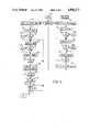
- FIG. 6is a flow chart of a MMU mapping program constructed according to the teachings of the invention.
- FIG. 7is a ROM map illustrating shift variables, masks, and modulos, which may be selected by the MMU program shown in FIG. 6;
- FIG. 8is a ROM map illustrating mapping commands and subcommands used by the MMU program shown in FIG. 6, as well as preselected values from the ROM map of FIG. 7;
- FIG. 9is a RAM map illustrating program variables used by the MMU program of FIG. 6;
- FIG. 10is a flow chart of a RMU mapping program constructed according to the teachings of the invention.
- FIG. 11is a flow chart of a RMU power up and reset program
- FIG. 12is a flow chart of a RMU timer program
- FIG. 13is a RAM map illustrating program variables used by the RMU programs of FIGS. 10, 11 and 12;
- FIG. 14illustrates certain of the program steps of the RMU program shown in FIG. 10.
- FIG. 1is a block diagram of a power line carrier based reefer monitoring system 10.
- System 10may include one or more separate electrical distribution power lines having reefers to be monitored, with two power lines 26 and 72 being shown for purposes of example.
- Power line 26will be called a local power line
- power line 72will be called a remote power line.
- System 10further includes a plurality of transportable refrigerated containers or reefers, such as reefer 12 associated with local power line 26 and reefer 13 associated with remote power line 72.
- Reefer 12includes a refrigeration unit 14 which conditions the air in a container 16, and reefer 13 includes a refrigeration unit 16 which conditions the air in a container 17.
- Reefers 12 and 13may be individually monitored by one of first and second different types of remote monitoring units (RMUs) 19 and 20, respectively, depending upon whether the reefer already has a computer based refrigeration monitor and controller 18 which can be communicated with.
- Remote monitoring unit 19is illustrated as being associated with a reefer 12 which has such a controller 18, and remote monitoring unit 19 will be referred to as an integrated remote monitoring unit (IRMU) 19.
- IRMUintegrated remote monitoring unit
- Reefer 13does not have a controller 18 and remote monitoring unit 20 will be referred to as a stand alone remote monitoring unit (SRMU) 20.
- the two different/typesmay be indiscriminately mixed on any power line.
- Controller 18may be the refrigeration monitor and controller set forth in U.S. Pat. No.
- the RMUsare monitored by a master monitoring unit (MMU) 22 which includes a central computer for preparing, transmitting and receiving messages.
- MMUmaster monitoring unit
- NCCUnetwork central control unit
- first power line interface 24is disposed between MMU 22 and the local electrical distribution power line 26 which extends to the locations of the plurality of reefers to be monitored. Communications between MMU 22 and NCCU 24 do not use power line 26, and a first message format 42 shown in FIG. 2 may be used which is tailored with minimal concern with electrical noise.
- NCCU 24includes a RS-232-C transmit receiver 28 for receiving messages from MMU 22 in the first format 42, translating means 30 for translating the first message format 42 to a second message format 51 shown in FIG. 3, modulator/demodulator means or carrier current transceiver (CCT) 31, and power line coupling means 32 which includes a coupling transformer and coupling capacitors for applying the modulated message to power line 26.
- the second format 51is tailored for the severe power line environment.
- Each RMUsuch as IRMU 19, includes a power line coupling interface 34 which includes a coupling transformer and coupling capacitors, a carrier current transceiver (CCT) 36 for demodulating messages received from power line 26 and for modulating messages to be applied to power line 26, and a computer 38 for processing the commands in messages received from MMU 22 and for preparing and sending second formatted messages back to MMU 22 via power line 26 and NCCU 24.
- a power line coupling interface 34which includes a coupling transformer and coupling capacitors
- CCTcarrier current transceiver
- MMU 22may monitor reefers associated with more than one power line, as shown in FIG. 1, with additional power lines, such as power line 72, being monitored by a radio link 74.
- Radio link 74includes a local central control unit (LCCU) 76 which includes a radio transmitter/receiver.
- LCCUlocal central control unit
- Each remote power line, such as remote power line 72includes a remote central control unit (RCCU) 78 which also has a transmitter/receiver.
- NCCU 24translates messages received from MMU 22 from the first message format 42 to the second message format 51.
- An address tag located in a field 48 of the first message format 42 and in a field 57 of the second message format 51provides a predetermined power line identification, which for purposes of example will be assumed to be an ASCII "A” for the local power line, an ASCII "B” for a first remote power line 72, etc. All RMUs, regardless of which power line they are connected to will only respond to messages which have an ASCII "A” in the address tag 57. If the message received by NCCU 24 from MMU 22 has an ASCII "A" in the address tag field 48, NCCU applies the message to local power line 26. If it has an identification other than an ASCII "A", LCCU 76 transmits the second formatted message by radio to all of the remote power lines.
- Each RCCU 78receives the broadcast message, and if the address tag bears its unique identifier, the addressed RCCU 78 swaps its identifier for an ASCII "A" in the address tag field 57 and applies the message to its associated remote power line 72. Responses by the RMUs connected to the remote power line 72 are received by RCCU 78 which then swaps its identifier for the ASCII "A" in the address tag field 57 and broadcasts the message back to the LCCU 76, which directs the message to MMU 22 via NCCU 24.
- all RMUsregardless of which power line they are connected to will see an ASCII "A" in the address tag field 57, and reefers and RMUs may be connected to any power line without modification.
- a message format which may be used for the first format 42is shown in FIG. 2.
- the first message format 42when prepared by MMU 22 for transmission to NCCU 24, may start with an optional synchronization field 43 of any desired number of bytes, followed by a one byte character 44 which delimits the start (STX) of a valid message.
- NCCU 24strips the synchronization field 43, if used, from the start of a message.
- STXstart
- the next two bytes 45are used to define an unsigned integer which indicates the packet length in bytes of the following data.
- the following dataincludes a one byte task number 46 assigned by MMU 22, which is an identification number used only by MMU 22.
- the identification numberis followed by a one byte character 47 which informs NCCU 24 as to the message type, i.e., the type of processing required.
- the messagemay be directed only to NCCU 24 per se, such as for setting up internal configurations; or it may be a message which is to be applied to power line 26 and directed to all of the the RMUs, or to a specifically addressed RMU.
- a variable length data field 48follows the message type identifier 47, with its contents depending upon the type of message to be processed. For example, if the message is to be applied to power line 26, the data field would contain an address tag, a universal or a specific RMU address, plus data relative to the type of command being sent.
- the address tagidentifies a specific power line, when there is more than one under the control of MMU 22, and it allows expansion when there is only one.
- a two byte error check field 49which is not part of the data packet defined by the packet length integer 45 follows, such as a field generated by using the cyclic redundancy check (CRC), i.e., a polynomial calculation performed on the message data bits.
- CRCcyclic redundancy check
- the first message format 42 when prepared by NCCU 24 for transmission to MMU 22includes the optional sync field 43, the starting character 44, and the two byte packet length 45.
- the task number used in field 46is the same task number previously assigned to the MMU request for which this message is a response.
- NCCU 24uses the one byte field 47 used by MMU 22 to indicate message type, to indicate success or failure in implementing the command received from MMU 22.
- the data field 48includes the data resulting from the MMU command, e.g., RMU status data, followed by the CRC error checking field 49.
- FIG. 3indicates the second message format 51, which is used for radio and power line communications.
- a message starting preamble 53includes at least three transition changes, required to synchronize communications between carrier receivers "listening" to the power line 26. The transitions are followed by ten logic ones.
- NCCU 24may use the same type-of-processing byte 47 described relative to the first message format 42 used between MMU 22 and NCCU 24, or NCCU 24 may tailor the message.
- a reply message from a RMUwill use the same byte character in field 55 that was in the command received.
- the address tag byte 57 for a message prepared by MMU 22 for the local power line 26is the same as that provided in the data field 48 of the first message format 42. As hereinbefore explained, the address tag field 57 destined for a remote power line will include the unique power line identifier of the selected remote power line.
- the next ten bytesdefine an address field 59.
- the address placed in field 59which is the same address contained in the data field 48 of the first format 42, may be an address unique to a specific RMU, or it may be a universal address recognized by all RMUs.
- a universal addressis used during system reset, and in the process of originally giving a RMU an unique address.
- the unique RMU addressis stored in non-volatile RAM 134.
- the one byte message type 55, the one byte address tag 57, and the ten byte RMU address 59, collectively called the power line prefix,are all in ASCII characters.
- the next field 61is the data field, and it contains data in non-ASCII characters, including control characters in ANSI X3.28 format. It will contain the specific command or task to be performed by a RMU.
- FIG. 4indicates the format 65 of all characters, prefix and data, which format includes a low start bit, eight data bits, and a high stop bit. Thus, there will always be at least one logic zero, i.e., the start bit, in every ten bit data character.
- the messageends with the two byte CRC error check field 63.
- a RMUWhen a RMU responds to a command from MMU 22, it will prepare a message in the second format 51 just described, inserting the data requested by the specific command from MMU 22 in the data field 61.
- MMU 22When MMU 22 desires to map addresses of the refrigerated containers or reefers 12 connected to monitoring system 50, it redefines the 10 byte RMU address field 59 shown in FIG. 3 to provide a mapping message 70, the format of which is shown in FIG. 5. When the message type in field 55 indicates mapping, each RMU will look for a mapping message in field 59, instead of treating it as an RMU address field.
- mapping message 70set forth either a total or a particular mapping address which, for example, will be recognized by all reefers connected to any given power line, or by a specific segment or bank of reefers.
- field 71may contain a universal address to which all RMUs will respond, or it may contain a predetermined vendor identifier to which only RMUs provided by the identified vendor will respond.
- the next three bytes 73set forth a general mapping command.
- the next byte 75identifies a specific mapping subcommand which identifies a processing procedure to be used in the mapping strategy of the invention.
- mapping subcommands or processing procedureswhich may be used are set forth in Table I
- the next byte 77is not used, but since this is an ASCII field, it must contain any ASCII numeric or alphanumeric character.
- the final byte 80is used by MMU 22 to provide a number which establishes the number range of modulo (16) to be used by the RMUs when generating or modulo (of 16) to be their random numbers.
- a random number generated by a RMUmust be within the range of numbers indicated by the number in field 80.
- the lower nibbleselects one of the 16 ranges, while the upper nibble is set to provide an ASCII ranged number.
- mapping subcommands in TABLE Iwhich will be described in more detail as exemplary programs which use them are described, all utilize the shift variable in field 80.
- FIG. 6is a flow chart of a mapping program 82 which may be used by MMU 22 in implementing the mapping method of the invention.
- FIG. 7is a ROM map 84 of a read-only memory storage location used by MMU 22 during the running of program 82 which illustrates: a) numbers, called "shift variables", which are selectively used in field 80 of mapping message format 70 shown in FIG. 5; b) 16 bit masks associated with the shift variables; and c) the number range or modulo associated with each shift variable and mask.
- FIG. 7is a ROM map 84 of a read-only memory storage location used by MMU 22 during the running of program 82 which illustrates: a) numbers, called "shift variables", which are selectively used in field 80 of mapping message format 70 shown in FIG. 5; b) 16 bit masks associated with the shift variables; and c) the number range or modulo associated with each shift variable and mask.
- FIG. 8is a ROM map 86 of a read-only memory storage location used by MMU 22 during the running of program 82 which illustrates a) certain modulos and shift variables from ROM map 84 that may be stored for specific use by program 82, according to the maximum number of reefers to be connected to monitoring system 50; b) the mapping command and subcommands; and c) program constants used by program 82.
- FIG. 9is a RAM map 88 illustrating a random-access storage location where certain program variables are stored during the running of program 82.
- the shift variable or number used in field 80 of the mapping message of FIG. 5is a number between 0 and 15. This number is set forth in the lower four bits of the byte located in field 80. The number dictates how many logic zeros are shifted left, starting with the most significant bit (MSB) of a sixteen bit mask originally containing sixteen logic ones. The highest number or modulo for each shift variable is also listed.
- MSBmost significant bit
- the random numberis logically AND'ed with the mask generated in response to the number found in field 80 of the mapping message 70. This automatically places a sixteen bit random number within the number range selected by MMU 22, as it removes the specified number of most significant bits from the random number.
- step 92checks to determine if the system has just been initialized, e.g., when power is initially applied to the MMU 22 at start-up, or after a power failure. If this is an initialization procedure, all of the reefers connected to monitoring system 10 must have their unique addresses logged in or mapped by MMU 22.
- Step 92proceeds to step 94 which selects a shift variable and stores the associated modulo in RAM 88 (FIG. 9). For example, step 94 may select a modulo, such as modulo "x", and the associated shift variable from ROM map 86 shown in FIG. 8. Modulo "x" is preselected from the sixteen possible numbers shown in FIG.
- shift variable 4may be selected and the random numbers will be generated between 0 and 4095. If shift variable 5 is selected, the random numbers will be generated between 0 and 2047.
- Step 96then prepares and sends a mapping command in the first format 42 wherein the mapping message 70 is disposed in data field 48.
- the mapping message 70would include the general mapping command in field 73 and the "initiate new map" subcommand in field 75.
- the mapping commandis translated to the second format 51 by NCCU 24 and applied to the power line 26.
- the mapping message 70is located in the RMU address field 59 of the second format 51.
- the RMUsdetect the mapping command and process the mapping message, as will be hereinafter described relative to the RMU program of FIG. 10.
- Program 82may have a delay loop to give a RMU whose random number is zero time to respond with its unique address, and then step 98 checks to see if a valid response to the mapping command was received. If a RMU responded with its address, step 100 addresses a polling reply to this RMU using its unique address, and this RMU now knows that it has been mapped into the monitoring system.
- Steps 98 and 100both proceed to step 102 which prepares and sends a mapping command having a mapping message which includes the "decrement map subcommand".
- Each RMUwill decrement its random number, and a RMU having a random number which was decremented to zero by this subcommand will respond with its unique address.
- Step 104checks for a valid response, and step 106 sends a reply to a RMU which responds.
- Step 108now decrements the stored modulo so the next step, step 110, will know when all numbers of the modulo have been checked.
- Step 110returns to step 98 until the modulo has been reduced to zero, at which time it branches to step 112.
- Step 112initiates a portion of program 82 which detects reefers which were not mapped by steps 94 through 110, such as due to message collisions by reefers having the same random number.
- Step 112selects another modulo from ROM map 86 of FIG. 8, such as modulo "y", and the associated shift variable, and step 114 incorporates it into a mapping command having a mapping message which includes the "general new map” subcommand. Since most of the reefers will have been mapped by the "initiate new map" subcommand, the shift variable number may be a much larger number, resulting in a much smaller modulo.
- the programthen loops through this smaller modulo in steps 116, 118, 120, 122, 124, 126 and 128, which are similar to steps 98 through 110.
- step 130increments the shift variable used for the general new map command and stores the new modulo.
- step 132checks to see if the shift variable has been incremented to 15. If it has not, step 134 prepares and sends a mapping command which contains the "shift map" subcommand, using the incremented value of the shift variable.
- Step 136looks for an ACK from a RMU, and if one is received, step 138 sends a reply. Step 138 and the "no" branch of step 136 return to step 120. This continues until step 132 finds that the shift variable has been incremented to 15, at which time the program exits at 140.
- Program 82is periodically entered to pick up new reefers which may have been connected to the monitoring system following initialization.
- step 92proceeds to step 142 which selects a shift variable, such as modulo "z", from ROM map 86, and it stores the associated modulo.
- the programthen repeats steps 114 through 140.
- FIG. 10is a flow chart of a RMU mapping command program 143 which implements the teachings of the invention.
- FIG. 11is an initialization and reset program 144
- FIG. 12is a timer program 146.
- Figure 13is a RAM map 148 which contains program variables used by the RMU programs 143, 144 and 146.
- the power up and reset program 144 shown in FIG. 11is entered during initialization of a RMU, during an internal reset, such as from a "dead man" reset procedure, and during an external reset initiated by MMU 22.
- the purpose of this programis to set a mapping flag shown in the RAM map 48 of FIG. 13, which flag is used by program 143. More specifically, program 144 is entered at 150 and step 152 determines if this is a power up or initialization procedure. If so, step 154 sets the mapping flag, to indicate that mapping of this RMU is required, and the program exits at 156. If step 152 finds that the RMU isn't being initialized, steps 158 and 160 check for internal and external resets. Upon either of these steps finding a reset, step 154 sets the mapping flag.
- the timing program 146 of FIG. 12is periodically entered at 162 to perform general timing functions, indicated at 164, and to check in step 166 to see if a timer referred to as a map inhibit delay timer (M.I.D.) is active. If so, step 168 decrements this timer. Step 169 determines if the M.I.D. timer has been decremented to zero. If it is zero, step 170 sets the mapping flag and the program exits at 171. If the M.I.D. timer is not zero, step 169 exits at 171.
- M.I.D.map inhibit delay timer
- step 174determines if a received command contains the general mapping command. If so, step 176 checks the mapping subcommand to determine the type of processing requested by MMU 22. If step 176 finds that the subcommand is "initiate new map", step 178 sets the mapping flag. The mapping flag will remain set until the RMU has been mapped into the monitoring system and has subsequently received a polling command from MMU 22 using the unique address of the RMU.
- Step 180then generates a sixteen bit random number and step 182 reads the shift variable portion 80 of the mapping message 70.
- Step 184prepares a mask of sixteen logic ones, and a number of logic zeros are shifted into the mask, starting from the MSB, with the number of logic zeros being equal to the shift variable found in field 80.
- Step 186performs a logical AND with the mask and the sixteen bit random number to provide a random number having a value within the modulo selected by MMU 22.
- Step 188checks to see if the result of the logical AND is zero. If it is not zero, the program returns at 190. If it is zero, the unique address will be returned if the mapping flag is set, as will be hereinafter explained.
- FIG. 14illustrates steps 180 thru 186 using a shift variable of 8 and a modulo of 256.
- the mask of logic oneshas eight logic zeros shifted into the mask from the MSB, and when this mask is AND'ed with the sixteen bit random number it removes the eight MSBs of the random number, producing a random number which cannot exceed the modulo of 256.
- step 176decrements the random number by one and proceeds to step 182 to read the shift variable.
- step 192checks to see if the mapping flag of the RMU is set. If it is not set, the RMU will not respond, and the program exits at 190. If step 192 finds the mapping flag set, step 194 prepares and sends a message to MMU 22 which includes its unique address in the data field.
- the RMUthen awaits an acknowledge (ACK) from MMU 22.
- ACKacknowledge
- a reply countermay be set to provide time sufficient to receive an ACK.
- Step 196checks for an ACK. If none is received, step 196 proceeds to exit 190. Only later, when MMU 22 returns with a poll command and the correct unique address will the mapping flag be reset. If an ACK is received using the address of the RMU, step 198 resets the mapping flag, and it sets the M.I.D. timer shown in RAM map 148.
- the M.I.D. timerfor example, may be set to a predetermined value such as one hour. The value is stored in the RMU's ROM. The mapping flag will be set when the M.I.D.
- step 174finds that the command is not a mapping command, but a polling command which specifically addresses the RMU, step 204 performs whatever function the polling command requires, and step 206 sets the M.I.D. timer to the predetermined value and resets the mapping flag. Step 206 returns at 208.
- step 210when found in step 210, skips step 178 which set the mapping flag, as it is looking only for RMUs which were missed by the initiate new map subcommand, or which were connected after system initialization. The remainder of the steps are as hereinbefore described.
- the decrement map subcommandwhen detected in step 214, as hereinbefore stated, decrements the random number by one in step 216.
- Step 216will decrement a random number which was previously decremented to zero, causing it to roll over.
- the mapping flagis not reset in response to receiving a reply from MMU 22, the rolled over random number will be used and decremented by the program until such time a new random number is generated by a command which uses step 180.
Landscapes
- Engineering & Computer Science (AREA)
- Power Engineering (AREA)
- Computer Networks & Wireless Communication (AREA)
- Signal Processing (AREA)
- Mobile Radio Communication Systems (AREA)
Abstract
Description
TABLE I ______________________________________ MAPPING SUBCOMMAND RMU PROCESS ______________________________________ Initiate New Map For Mapping A Large Number of Reefers General New Map For Mapping A Smaller Number of Reefers Change Shift Map For Reducing the Modulo Decrement Map For Decrementing Random Numbers ______________________________________
Claims (20)
Priority Applications (1)
| Application Number | Priority Date | Filing Date | Title |
|---|---|---|---|
| US07/189,896US4896277A (en) | 1988-05-03 | 1988-05-03 | Method of mapping refrigerated containers in a power line carrier based monitoring system |
Applications Claiming Priority (1)
| Application Number | Priority Date | Filing Date | Title |
|---|---|---|---|
| US07/189,896US4896277A (en) | 1988-05-03 | 1988-05-03 | Method of mapping refrigerated containers in a power line carrier based monitoring system |
Publications (1)
| Publication Number | Publication Date |
|---|---|
| US4896277Atrue US4896277A (en) | 1990-01-23 |
Family
ID=22699220
Family Applications (1)
| Application Number | Title | Priority Date | Filing Date |
|---|---|---|---|
| US07/189,896Expired - LifetimeUS4896277A (en) | 1988-05-03 | 1988-05-03 | Method of mapping refrigerated containers in a power line carrier based monitoring system |
Country Status (1)
| Country | Link |
|---|---|
| US (1) | US4896277A (en) |
Cited By (48)
| Publication number | Priority date | Publication date | Assignee | Title |
|---|---|---|---|---|
| EP0598297A2 (en) | 1992-11-14 | 1994-05-25 | Siemens Measurements Limited | A polled communications network |
| US5349644A (en) | 1992-06-30 | 1994-09-20 | Electronic Innovators, Inc. | Distributed intelligence engineering casualty and damage control management system using an AC power line carrier-current lan |
| US5353009A (en)* | 1991-01-04 | 1994-10-04 | Csir | Communication system |
| US5392218A (en)* | 1993-06-14 | 1995-02-21 | Sundstrand Corporation | Electrically isolated approach to sensing dc voltages referenced to a floating ground |
| US5442810A (en)* | 1992-11-24 | 1995-08-15 | Qualcomm Incorporated | Tractor-trailer electronic transmission path |
| US5452344A (en)* | 1992-05-29 | 1995-09-19 | Datran Systems Corporation | Communication over power lines |
| US5568121A (en)* | 1993-05-27 | 1996-10-22 | Lamensdorf; David M. | Wireless system for sensing information at remote locations and communicating with a main monitoring center |
| US5818821A (en) | 1994-12-30 | 1998-10-06 | Intelogis, Inc. | Universal lan power line carrier repeater system and method |
| US5835005A (en)* | 1994-07-13 | 1998-11-10 | Omron Corporation | Power-line data transmission method and system utilizing relay stations |
| EP0858143A3 (en)* | 1997-02-05 | 1999-10-06 | Deutsche Telekom AG | Monitoring device for mains-operated houshold devices |
| US5973610A (en)* | 1993-11-03 | 1999-10-26 | Lanng & Stelman A/S | System for automated selection of a communications unit for refrigerating containers |
| US5983353A (en)* | 1997-01-21 | 1999-11-09 | Dell Usa, L.P. | System and method for activating a deactivated device by standardized messaging in a network |
| US5991806A (en)* | 1997-06-09 | 1999-11-23 | Dell Usa, L.P. | Dynamic system control via messaging in a network management system |
| US6281677B1 (en) | 1999-11-04 | 2001-08-28 | International Business Machines Corporation | Method for defect marking and analysis of thin film hard disks |
| EP1253513A1 (en)* | 2001-04-27 | 2002-10-30 | Trialog | Method of generating a random number sequence and apparatus implementing the method |
| US20030174728A1 (en)* | 2002-03-13 | 2003-09-18 | Nec Corporation | Multiplex transmission system for reporting alert information to the conversion device on the receiving side without using a dedicated frame |
| US20030189495A1 (en)* | 2002-04-03 | 2003-10-09 | Pettler Peter R. | Method and system for controlling a selected electrical load in a building |
| EP1471661A1 (en)* | 2003-03-31 | 2004-10-27 | Magnetek S.p.A. | Packet communication between a collecting unit and a plurality of control devices over the power supply line |
| US20050232299A1 (en)* | 2000-04-19 | 2005-10-20 | Serconet, Ltd. | Network combining wired and non-wired segments |
| US20060092962A1 (en)* | 1998-07-28 | 2006-05-04 | Serconet, Ltd | Local area network of serial intelligent cells |
| WO2007059778A1 (en)* | 2005-11-25 | 2007-05-31 | Johnson Controls Denmark Aps | Systems and methods for power line communication with refrigeration containers |
| US20070147433A1 (en)* | 2003-03-13 | 2007-06-28 | Serconet Ltd. | Telephone system having multiple distinct sources and accessories therefor |
| US20070208876A1 (en)* | 2002-05-06 | 2007-09-06 | Davis Ian E | Method and apparatus for efficiently processing data packets in a computer network |
| US20070267473A1 (en)* | 2006-05-18 | 2007-11-22 | Xata Corporation | Portable data storage module |
| US20070267509A1 (en)* | 2006-05-18 | 2007-11-22 | Xata Corporation | Environmental condition monitoring of a container |
| US20080049742A1 (en)* | 2006-08-22 | 2008-02-28 | Deepak Bansal | System and method for ecmp load sharing |
| US20080205407A1 (en)* | 2000-11-17 | 2008-08-28 | Andrew Chang | Network switch cross point |
| US20080222200A1 (en)* | 2007-03-08 | 2008-09-11 | Microsoft Corporation | Rich data tunneling |
| US20090279546A1 (en)* | 2002-05-06 | 2009-11-12 | Ian Edward Davis | Flexible method for processing data packets in a network routing system for enhanced efficiency and monitoring capability |
| US20090279548A1 (en)* | 2002-05-06 | 2009-11-12 | Foundry Networks, Inc. | Pipeline method and system for switching packets |
| US20090279561A1 (en)* | 2000-11-17 | 2009-11-12 | Foundry Networks, Inc. | Backplane Interface Adapter |
| US20090282148A1 (en)* | 2007-07-18 | 2009-11-12 | Foundry Networks, Inc. | Segmented crc design in high speed networks |
| US20090279558A1 (en)* | 2002-05-06 | 2009-11-12 | Ian Edward Davis | Network routing apparatus for enhanced efficiency and monitoring capability |
| US20090279549A1 (en)* | 2005-12-28 | 2009-11-12 | Foundry Networks, Inc. | Hitless software upgrades |
| US20090279441A1 (en)* | 2007-01-11 | 2009-11-12 | Foundry Networks, Inc. | Techniques for transmitting failure detection protocol packets |
| US20090279559A1 (en)* | 2004-03-26 | 2009-11-12 | Foundry Networks, Inc., A Delaware Corporation | Method and apparatus for aggregating input data streams |
| US20090282322A1 (en)* | 2007-07-18 | 2009-11-12 | Foundry Networks, Inc. | Techniques for segmented crc design in high speed networks |
| US20090279423A1 (en)* | 2006-11-22 | 2009-11-12 | Foundry Networks, Inc. | Recovering from Failures Without Impact on Data Traffic in a Shared Bus Architecture |
| US20100034215A1 (en)* | 2000-11-17 | 2010-02-11 | Foundry Networks, Inc. | Backplane Interface Adapter with Error Control |
| US20100046521A1 (en)* | 2003-05-15 | 2010-02-25 | Foundry Networks, Inc. | System and Method for High Speed Packet Transmission |
| US20100246588A1 (en)* | 2002-05-06 | 2010-09-30 | Foundry Networks, Inc. | System architecture for very fast ethernet blade |
| US7953923B2 (en) | 2004-10-29 | 2011-05-31 | Foundry Networks, Llc | Double density content addressable memory (CAM) lookup scheme |
| US8090901B2 (en) | 2009-05-14 | 2012-01-03 | Brocade Communications Systems, Inc. | TCAM management approach that minimize movements |
| US8149839B1 (en) | 2007-09-26 | 2012-04-03 | Foundry Networks, Llc | Selection of trunk ports and paths using rotation |
| WO2013023962A1 (en) | 2011-08-17 | 2013-02-21 | Apm Terminals Management B.V. | Management system for refrigerated containers |
| US8599850B2 (en) | 2009-09-21 | 2013-12-03 | Brocade Communications Systems, Inc. | Provisioning single or multistage networks using ethernet service instances (ESIs) |
| US8730961B1 (en) | 2004-04-26 | 2014-05-20 | Foundry Networks, Llc | System and method for optimizing router lookup |
| CN105681146A (en)* | 2016-03-18 | 2016-06-15 | 宁波三星智能电气有限公司 | Multiple network internetwork coordination method used for broadband power line carrier communication network |
Citations (14)
| Publication number | Priority date | Publication date | Assignee | Title |
|---|---|---|---|---|
| US104003A (en)* | 1870-06-07 | Improvement in stump-extractor | ||
| US4234926A (en)* | 1978-12-05 | 1980-11-18 | Sealand Service Inc. | System & method for monitoring & diagnosing faults in environmentally controlled containers, such system and method being especially adapted for remote computer controlled monitoring of numerous transportable containers over existing on-site power wiring |
| US4334307A (en)* | 1979-12-28 | 1982-06-08 | Honeywell Information Systems Inc. | Data processing system with self testing and configuration mapping capability |
| US4402191A (en)* | 1982-01-05 | 1983-09-06 | Thermo King Corporation | Evaporator section for container refrigeration unit |
| US4409797A (en)* | 1982-06-10 | 1983-10-18 | Thermo King Corporation | Condenser coil and fan mount for a transport refrigeration unit |
| US4424684A (en)* | 1982-01-05 | 1984-01-10 | Thermo King Corporation | Condenser section for container refrigeration unit |
| UST104003I4 (en) | 1982-11-09 | 1984-03-06 | Synchronous data link slow-poll protocol | |
| US4488256A (en)* | 1981-11-23 | 1984-12-11 | Motorola, Inc. | Memory management unit having means for detecting and preventing mapping conflicts |
| US4658243A (en)* | 1983-11-08 | 1987-04-14 | Nittan Company, Limited | Surveillance control apparatus for security system |
| US4663725A (en)* | 1985-02-15 | 1987-05-05 | Thermo King Corporation | Microprocessor based control system and method providing better performance and better operation of a shipping container refrigeration system |
| US4683531A (en)* | 1984-07-02 | 1987-07-28 | Ncr Corporation | Polling method for data processing system |
| US4727475A (en)* | 1984-05-18 | 1988-02-23 | Frederick Kiremidjian | Self-configuring modular computer system with automatic address initialization |
| US4742335A (en)* | 1986-06-18 | 1988-05-03 | Baker Industries, Inc. | Sequential and/or random polling system with virtually instantaneous response time |
| US4780816A (en)* | 1986-05-16 | 1988-10-25 | The United States Of America As Represented By The Secretary Of The Army | Key-to-address transformations |
- 1988
- 1988-05-03USUS07/189,896patent/US4896277A/ennot_activeExpired - Lifetime
Patent Citations (14)
| Publication number | Priority date | Publication date | Assignee | Title |
|---|---|---|---|---|
| US104003A (en)* | 1870-06-07 | Improvement in stump-extractor | ||
| US4234926A (en)* | 1978-12-05 | 1980-11-18 | Sealand Service Inc. | System & method for monitoring & diagnosing faults in environmentally controlled containers, such system and method being especially adapted for remote computer controlled monitoring of numerous transportable containers over existing on-site power wiring |
| US4334307A (en)* | 1979-12-28 | 1982-06-08 | Honeywell Information Systems Inc. | Data processing system with self testing and configuration mapping capability |
| US4488256A (en)* | 1981-11-23 | 1984-12-11 | Motorola, Inc. | Memory management unit having means for detecting and preventing mapping conflicts |
| US4402191A (en)* | 1982-01-05 | 1983-09-06 | Thermo King Corporation | Evaporator section for container refrigeration unit |
| US4424684A (en)* | 1982-01-05 | 1984-01-10 | Thermo King Corporation | Condenser section for container refrigeration unit |
| US4409797A (en)* | 1982-06-10 | 1983-10-18 | Thermo King Corporation | Condenser coil and fan mount for a transport refrigeration unit |
| UST104003I4 (en) | 1982-11-09 | 1984-03-06 | Synchronous data link slow-poll protocol | |
| US4658243A (en)* | 1983-11-08 | 1987-04-14 | Nittan Company, Limited | Surveillance control apparatus for security system |
| US4727475A (en)* | 1984-05-18 | 1988-02-23 | Frederick Kiremidjian | Self-configuring modular computer system with automatic address initialization |
| US4683531A (en)* | 1984-07-02 | 1987-07-28 | Ncr Corporation | Polling method for data processing system |
| US4663725A (en)* | 1985-02-15 | 1987-05-05 | Thermo King Corporation | Microprocessor based control system and method providing better performance and better operation of a shipping container refrigeration system |
| US4780816A (en)* | 1986-05-16 | 1988-10-25 | The United States Of America As Represented By The Secretary Of The Army | Key-to-address transformations |
| US4742335A (en)* | 1986-06-18 | 1988-05-03 | Baker Industries, Inc. | Sequential and/or random polling system with virtually instantaneous response time |
Cited By (119)
| Publication number | Priority date | Publication date | Assignee | Title |
|---|---|---|---|---|
| US5353009A (en)* | 1991-01-04 | 1994-10-04 | Csir | Communication system |
| US5452344A (en)* | 1992-05-29 | 1995-09-19 | Datran Systems Corporation | Communication over power lines |
| US5349644A (en) | 1992-06-30 | 1994-09-20 | Electronic Innovators, Inc. | Distributed intelligence engineering casualty and damage control management system using an AC power line carrier-current lan |
| EP0598297A3 (en)* | 1992-11-14 | 1995-12-27 | Siemens Measurements Ltd | A polled communications network. |
| EP0598297A2 (en) | 1992-11-14 | 1994-05-25 | Siemens Measurements Limited | A polled communications network |
| US5442810A (en)* | 1992-11-24 | 1995-08-15 | Qualcomm Incorporated | Tractor-trailer electronic transmission path |
| US5568121A (en)* | 1993-05-27 | 1996-10-22 | Lamensdorf; David M. | Wireless system for sensing information at remote locations and communicating with a main monitoring center |
| US5392218A (en)* | 1993-06-14 | 1995-02-21 | Sundstrand Corporation | Electrically isolated approach to sensing dc voltages referenced to a floating ground |
| US5973610A (en)* | 1993-11-03 | 1999-10-26 | Lanng & Stelman A/S | System for automated selection of a communications unit for refrigerating containers |
| US5835005A (en)* | 1994-07-13 | 1998-11-10 | Omron Corporation | Power-line data transmission method and system utilizing relay stations |
| US5818821A (en) | 1994-12-30 | 1998-10-06 | Intelogis, Inc. | Universal lan power line carrier repeater system and method |
| US5983353A (en)* | 1997-01-21 | 1999-11-09 | Dell Usa, L.P. | System and method for activating a deactivated device by standardized messaging in a network |
| EP0858143A3 (en)* | 1997-02-05 | 1999-10-06 | Deutsche Telekom AG | Monitoring device for mains-operated houshold devices |
| US5991806A (en)* | 1997-06-09 | 1999-11-23 | Dell Usa, L.P. | Dynamic system control via messaging in a network management system |
| US8885659B2 (en) | 1998-07-28 | 2014-11-11 | Conversant Intellectual Property Management Incorporated | Local area network of serial intelligent cells |
| US7978726B2 (en) | 1998-07-28 | 2011-07-12 | Mosaid Technologies Incorporated | Local area network of serial intelligent cells |
| US8908673B2 (en) | 1998-07-28 | 2014-12-09 | Conversant Intellectual Property Management Incorporated | Local area network of serial intelligent cells |
| US20080219288A1 (en)* | 1998-07-28 | 2008-09-11 | Israeli Company Of Serconet Ltd. | Local area network of serial intelligent cells |
| US8885660B2 (en) | 1998-07-28 | 2014-11-11 | Conversant Intellectual Property Management Incorporated | Local area network of serial intelligent cells |
| US7424031B2 (en) | 1998-07-28 | 2008-09-09 | Serconet, Ltd. | Local area network of serial intelligent cells |
| US20060092962A1 (en)* | 1998-07-28 | 2006-05-04 | Serconet, Ltd | Local area network of serial intelligent cells |
| US7852874B2 (en) | 1998-07-28 | 2010-12-14 | Mosaid Technologies Incorporated | Local area network of serial intelligent cells |
| US20070147413A1 (en)* | 1998-07-28 | 2007-06-28 | Israeli Company Of Serconet Ltd. | Local area network of serial intelligent cells |
| US8867523B2 (en) | 1998-07-28 | 2014-10-21 | Conversant Intellectual Property Management Incorporated | Local area network of serial intelligent cells |
| SG88793A1 (en)* | 1999-11-04 | 2002-05-21 | Ibm | Method for defect marking and analysis of thin film hard disks |
| US6281677B1 (en) | 1999-11-04 | 2001-08-28 | International Business Machines Corporation | Method for defect marking and analysis of thin film hard disks |
| US8848725B2 (en) | 2000-04-19 | 2014-09-30 | Conversant Intellectual Property Management Incorporated | Network combining wired and non-wired segments |
| US8873575B2 (en) | 2000-04-19 | 2014-10-28 | Conversant Intellectual Property Management Incorporated | Network combining wired and non-wired segments |
| US20100135480A1 (en)* | 2000-04-19 | 2010-06-03 | Mosaid Technologies Incorporated | Network combining wired and non-wired segments |
| US20100135479A1 (en)* | 2000-04-19 | 2010-06-03 | Mosaid Technologies Incorporated | Network combining wired and non-wired segments |
| US8873586B2 (en) | 2000-04-19 | 2014-10-28 | Conversant Intellectual Property Management Incorporated | Network combining wired and non-wired segments |
| US20050232299A1 (en)* | 2000-04-19 | 2005-10-20 | Serconet, Ltd. | Network combining wired and non-wired segments |
| US7876767B2 (en) | 2000-04-19 | 2011-01-25 | Mosaid Technologies Incorporated | Network combining wired and non-wired segments |
| US8867506B2 (en) | 2000-04-19 | 2014-10-21 | Conversant Intellectual Property Management Incorporated | Network combining wired and non-wired segments |
| US8982903B2 (en) | 2000-04-19 | 2015-03-17 | Conversant Intellectual Property Management Inc. | Network combining wired and non-wired segments |
| US7933297B2 (en) | 2000-04-19 | 2011-04-26 | Mosaid Technologies Incorporated | Network combining wired and non-wired segments |
| US8982904B2 (en) | 2000-04-19 | 2015-03-17 | Conversant Intellectual Property Management Inc. | Network combining wired and non-wired segments |
| US20090279561A1 (en)* | 2000-11-17 | 2009-11-12 | Foundry Networks, Inc. | Backplane Interface Adapter |
| US7948872B2 (en) | 2000-11-17 | 2011-05-24 | Foundry Networks, Llc | Backplane interface adapter with error control and redundant fabric |
| US8514716B2 (en) | 2000-11-17 | 2013-08-20 | Foundry Networks, Llc | Backplane interface adapter with error control and redundant fabric |
| US8619781B2 (en) | 2000-11-17 | 2013-12-31 | Foundry Networks, Llc | Backplane interface adapter with error control and redundant fabric |
| US7995580B2 (en) | 2000-11-17 | 2011-08-09 | Foundry Networks, Inc. | Backplane interface adapter with error control and redundant fabric |
| US7978702B2 (en) | 2000-11-17 | 2011-07-12 | Foundry Networks, Llc | Backplane interface adapter |
| US20080205407A1 (en)* | 2000-11-17 | 2008-08-28 | Andrew Chang | Network switch cross point |
| US20100034215A1 (en)* | 2000-11-17 | 2010-02-11 | Foundry Networks, Inc. | Backplane Interface Adapter with Error Control |
| US9030937B2 (en) | 2000-11-17 | 2015-05-12 | Foundry Networks, Llc | Backplane interface adapter with error control and redundant fabric |
| US8964754B2 (en) | 2000-11-17 | 2015-02-24 | Foundry Networks, Llc | Backplane interface adapter with error control and redundant fabric |
| FR2824153A1 (en)* | 2001-04-27 | 2002-10-31 | Trialog | METHOD FOR PRODUCING A SEQUENCE OF RANDOM NUMBERS AND DEVICE IMPLEMENTING THE METHOD |
| EP1253513A1 (en)* | 2001-04-27 | 2002-10-30 | Trialog | Method of generating a random number sequence and apparatus implementing the method |
| US20030174728A1 (en)* | 2002-03-13 | 2003-09-18 | Nec Corporation | Multiplex transmission system for reporting alert information to the conversion device on the receiving side without using a dedicated frame |
| US7471697B2 (en)* | 2002-03-13 | 2008-12-30 | Nec Corporation | Multiplex transmission system for reporting alert information to the conversion device on the receiving side without using a dedicated frame |
| US20030189495A1 (en)* | 2002-04-03 | 2003-10-09 | Pettler Peter R. | Method and system for controlling a selected electrical load in a building |
| US20100246588A1 (en)* | 2002-05-06 | 2010-09-30 | Foundry Networks, Inc. | System architecture for very fast ethernet blade |
| US8989202B2 (en) | 2002-05-06 | 2015-03-24 | Foundry Networks, Llc | Pipeline method and system for switching packets |
| US20090279546A1 (en)* | 2002-05-06 | 2009-11-12 | Ian Edward Davis | Flexible method for processing data packets in a network routing system for enhanced efficiency and monitoring capability |
| US8194666B2 (en) | 2002-05-06 | 2012-06-05 | Foundry Networks, Llc | Flexible method for processing data packets in a network routing system for enhanced efficiency and monitoring capability |
| US8170044B2 (en) | 2002-05-06 | 2012-05-01 | Foundry Networks, Llc | Pipeline method and system for switching packets |
| US20090279548A1 (en)* | 2002-05-06 | 2009-11-12 | Foundry Networks, Inc. | Pipeline method and system for switching packets |
| US20070208876A1 (en)* | 2002-05-06 | 2007-09-06 | Davis Ian E | Method and apparatus for efficiently processing data packets in a computer network |
| US8671219B2 (en) | 2002-05-06 | 2014-03-11 | Foundry Networks, Llc | Method and apparatus for efficiently processing data packets in a computer network |
| US20090279558A1 (en)* | 2002-05-06 | 2009-11-12 | Ian Edward Davis | Network routing apparatus for enhanced efficiency and monitoring capability |
| US7813367B2 (en) | 2002-05-06 | 2010-10-12 | Foundry Networks, Inc. | Pipeline method and system for switching packets |
| US20110002340A1 (en)* | 2002-05-06 | 2011-01-06 | Foundry Networks, Inc. | Pipeline method and system for switching packets |
| US7830884B2 (en) | 2002-05-06 | 2010-11-09 | Foundry Networks, Llc | Flexible method for processing data packets in a network routing system for enhanced efficiency and monitoring capability |
| US7656904B2 (en) | 2003-03-13 | 2010-02-02 | Mosaid Technologies Incorporated | Telephone system having multiple distinct sources and accessories therefor |
| US20070147433A1 (en)* | 2003-03-13 | 2007-06-28 | Serconet Ltd. | Telephone system having multiple distinct sources and accessories therefor |
| EP1471661A1 (en)* | 2003-03-31 | 2004-10-27 | Magnetek S.p.A. | Packet communication between a collecting unit and a plurality of control devices over the power supply line |
| US20100046521A1 (en)* | 2003-05-15 | 2010-02-25 | Foundry Networks, Inc. | System and Method for High Speed Packet Transmission |
| US20100061393A1 (en)* | 2003-05-15 | 2010-03-11 | Foundry Networks, Inc. | System and Method for High Speed Packet Transmission |
| US9461940B2 (en) | 2003-05-15 | 2016-10-04 | Foundry Networks, Llc | System and method for high speed packet transmission |
| US8811390B2 (en) | 2003-05-15 | 2014-08-19 | Foundry Networks, Llc | System and method for high speed packet transmission |
| US8718051B2 (en) | 2003-05-15 | 2014-05-06 | Foundry Networks, Llc | System and method for high speed packet transmission |
| US8493988B2 (en) | 2004-03-26 | 2013-07-23 | Foundry Networks, Llc | Method and apparatus for aggregating input data streams |
| US9338100B2 (en) | 2004-03-26 | 2016-05-10 | Foundry Networks, Llc | Method and apparatus for aggregating input data streams |
| US20090279559A1 (en)* | 2004-03-26 | 2009-11-12 | Foundry Networks, Inc., A Delaware Corporation | Method and apparatus for aggregating input data streams |
| US7817659B2 (en) | 2004-03-26 | 2010-10-19 | Foundry Networks, Llc | Method and apparatus for aggregating input data streams |
| US8730961B1 (en) | 2004-04-26 | 2014-05-20 | Foundry Networks, Llc | System and method for optimizing router lookup |
| US7953922B2 (en) | 2004-10-29 | 2011-05-31 | Foundry Networks, Llc | Double density content addressable memory (CAM) lookup scheme |
| US7953923B2 (en) | 2004-10-29 | 2011-05-31 | Foundry Networks, Llc | Double density content addressable memory (CAM) lookup scheme |
| US20080291850A1 (en)* | 2005-11-25 | 2008-11-27 | Johnson Controls Denmark Aps | Systems and Methods for Power Line Communication with Refrigeration Containers |
| DE112006003196T5 (en) | 2005-11-25 | 2008-10-16 | Johnson Controls Denmark Aps | Systems and methods for powerline communication with refrigerated containers |
| WO2007059778A1 (en)* | 2005-11-25 | 2007-05-31 | Johnson Controls Denmark Aps | Systems and methods for power line communication with refrigeration containers |
| US8448162B2 (en) | 2005-12-28 | 2013-05-21 | Foundry Networks, Llc | Hitless software upgrades |
| US9378005B2 (en) | 2005-12-28 | 2016-06-28 | Foundry Networks, Llc | Hitless software upgrades |
| US20090279549A1 (en)* | 2005-12-28 | 2009-11-12 | Foundry Networks, Inc. | Hitless software upgrades |
| US7401741B2 (en) | 2006-05-18 | 2008-07-22 | Xata Corporation | Portable data storage module |
| US20070267473A1 (en)* | 2006-05-18 | 2007-11-22 | Xata Corporation | Portable data storage module |
| US20070267509A1 (en)* | 2006-05-18 | 2007-11-22 | Xata Corporation | Environmental condition monitoring of a container |
| US20080251588A1 (en)* | 2006-05-18 | 2008-10-16 | Xata Corporation | Portable data storage module |
| US7784707B2 (en) | 2006-05-18 | 2010-08-31 | Xata Corporation | Environmental condition monitoring of a container |
| US7802729B2 (en) | 2006-05-18 | 2010-09-28 | Xata Corporation | Portable data storage module |
| US7903654B2 (en) | 2006-08-22 | 2011-03-08 | Foundry Networks, Llc | System and method for ECMP load sharing |
| US20080049742A1 (en)* | 2006-08-22 | 2008-02-28 | Deepak Bansal | System and method for ecmp load sharing |
| US20110044340A1 (en)* | 2006-08-22 | 2011-02-24 | Foundry Networks, Llc | System and method for ecmp load sharing |
| US9030943B2 (en) | 2006-11-22 | 2015-05-12 | Foundry Networks, Llc | Recovering from failures without impact on data traffic in a shared bus architecture |
| US20090279423A1 (en)* | 2006-11-22 | 2009-11-12 | Foundry Networks, Inc. | Recovering from Failures Without Impact on Data Traffic in a Shared Bus Architecture |
| US8238255B2 (en) | 2006-11-22 | 2012-08-07 | Foundry Networks, Llc | Recovering from failures without impact on data traffic in a shared bus architecture |
| US20090279441A1 (en)* | 2007-01-11 | 2009-11-12 | Foundry Networks, Inc. | Techniques for transmitting failure detection protocol packets |
| US7978614B2 (en) | 2007-01-11 | 2011-07-12 | Foundry Network, LLC | Techniques for detecting non-receipt of fault detection protocol packets |
| US9112780B2 (en) | 2007-01-11 | 2015-08-18 | Foundry Networks, Llc | Techniques for processing incoming failure detection protocol packets |
| US8395996B2 (en) | 2007-01-11 | 2013-03-12 | Foundry Networks, Llc | Techniques for processing incoming failure detection protocol packets |
| US8155011B2 (en) | 2007-01-11 | 2012-04-10 | Foundry Networks, Llc | Techniques for using dual memory structures for processing failure detection protocol packets |
| US20090279440A1 (en)* | 2007-01-11 | 2009-11-12 | Foundry Networks, Inc. | Techniques for processing incoming failure detection protocol packets |
| US20090279541A1 (en)* | 2007-01-11 | 2009-11-12 | Foundry Networks, Inc. | Techniques for detecting non-receipt of fault detection protocol packets |
| US20080222200A1 (en)* | 2007-03-08 | 2008-09-11 | Microsoft Corporation | Rich data tunneling |
| US7747634B2 (en)* | 2007-03-08 | 2010-06-29 | Microsoft Corporation | Rich data tunneling |
| US20090282148A1 (en)* | 2007-07-18 | 2009-11-12 | Foundry Networks, Inc. | Segmented crc design in high speed networks |
| US8037399B2 (en) | 2007-07-18 | 2011-10-11 | Foundry Networks, Llc | Techniques for segmented CRC design in high speed networks |
| US20090282322A1 (en)* | 2007-07-18 | 2009-11-12 | Foundry Networks, Inc. | Techniques for segmented crc design in high speed networks |
| US8271859B2 (en)* | 2007-07-18 | 2012-09-18 | Foundry Networks Llc | Segmented CRC design in high speed networks |
| US8149839B1 (en) | 2007-09-26 | 2012-04-03 | Foundry Networks, Llc | Selection of trunk ports and paths using rotation |
| US8509236B2 (en) | 2007-09-26 | 2013-08-13 | Foundry Networks, Llc | Techniques for selecting paths and/or trunk ports for forwarding traffic flows |
| US8090901B2 (en) | 2009-05-14 | 2012-01-03 | Brocade Communications Systems, Inc. | TCAM management approach that minimize movements |
| US8599850B2 (en) | 2009-09-21 | 2013-12-03 | Brocade Communications Systems, Inc. | Provisioning single or multistage networks using ethernet service instances (ESIs) |
| US9166818B2 (en) | 2009-09-21 | 2015-10-20 | Brocade Communications Systems, Inc. | Provisioning single or multistage networks using ethernet service instances (ESIs) |
| WO2013023962A1 (en) | 2011-08-17 | 2013-02-21 | Apm Terminals Management B.V. | Management system for refrigerated containers |
| US9766600B2 (en) | 2011-08-17 | 2017-09-19 | Apm Terminals Management B.V. | Management system for refrigerated containers |
| CN105681146A (en)* | 2016-03-18 | 2016-06-15 | 宁波三星智能电气有限公司 | Multiple network internetwork coordination method used for broadband power line carrier communication network |
| CN105681146B (en)* | 2016-03-18 | 2018-12-11 | 宁波三星医疗电气股份有限公司 | A kind of Multi net voting internetwork coordination method for power wire broadband carrier communication network |
Similar Documents
| Publication | Publication Date | Title |
|---|---|---|
| US4896277A (en) | Method of mapping refrigerated containers in a power line carrier based monitoring system | |
| EP0074864B1 (en) | System and method for name-lookup in a local area network data communication system | |
| US4430651A (en) | Expandable and contractible local area network system | |
| US5295140A (en) | Method for multi-purpose utilization of resources in a communication system | |
| US4410889A (en) | System and method for synchronizing variable-length messages in a local area network data communication system | |
| US5278833A (en) | Method for providing reserved communication access using multiple random access resources | |
| US5072374A (en) | Method for communicating among a plurality of programmable logic controllers each having a dma controller | |
| US4601586A (en) | Solicited message packet transfer system | |
| US4814984A (en) | Computer network system with contention mode for selecting master | |
| US5297144A (en) | Reservation-based polling protocol for a wireless data communications network | |
| US5708831A (en) | Method of bus address assignment | |
| US5586269A (en) | Communication control device and method for automatically determining a self-address | |
| WO1992017955A1 (en) | Method for controlling the scheduling of multiple access to communication resources | |
| CA1212479A (en) | Distributed computer control system with variable transfer monitor timers | |
| BRPI9909104B1 (en) | Method and apparatus for assigning broadcast code for reverse common channel message in cdma communication system | |
| US4516205A (en) | Access control of data transmission network | |
| US5502438A (en) | Address management for remote terminals in digital loop transmission systems | |
| EP1113591B1 (en) | System, method and apparatus for radio communication | |
| JPH05219077A (en) | Multiple station bus system and station using such system | |
| JPH03500237A (en) | multi-access communication system | |
| CN111083016B (en) | Polling table processing method and device, storage medium and equipment | |
| KR960015469B1 (en) | Remote booting method of network system | |
| CA1208736A (en) | System and method for name-lookup in a local area network data communication system | |
| JP3067160B2 (en) | Communication control device | |
| JP3345223B2 (en) | Satellite communication method and central and terminal stations |
Legal Events
| Date | Code | Title | Description |
|---|---|---|---|
| AS | Assignment | Owner name:THERMO KING CORPORATION, 314 WEST 90TH STREET, MIN Free format text:ASSIGNMENT OF ASSIGNORS INTEREST.;ASSIGNORS:VERCELLOTTI, LEONARD C.;ANDERSON, ARTHUR A.;REEL/FRAME:004899/0401 Effective date:19880429 Owner name:THERMO KING CORPORATION, A CORP. OF DE,MINNESOTA Free format text:ASSIGNMENT OF ASSIGNORS INTEREST;ASSIGNORS:VERCELLOTTI, LEONARD C.;ANDERSON, ARTHUR A.;REEL/FRAME:004899/0401 Effective date:19880429 | |
| STCF | Information on status: patent grant | Free format text:PATENTED CASE | |
| FPAY | Fee payment | Year of fee payment:4 | |
| FEPP | Fee payment procedure | Free format text:PAYOR NUMBER ASSIGNED (ORIGINAL EVENT CODE: ASPN); ENTITY STATUS OF PATENT OWNER: LARGE ENTITY | |
| FPAY | Fee payment | Year of fee payment:8 | |
| FPAY | Fee payment | Year of fee payment:12 | |
| FEPP | Fee payment procedure | Free format text:PAYER NUMBER DE-ASSIGNED (ORIGINAL EVENT CODE: RMPN); ENTITY STATUS OF PATENT OWNER: LARGE ENTITY Free format text:PAYOR NUMBER ASSIGNED (ORIGINAL EVENT CODE: ASPN); ENTITY STATUS OF PATENT OWNER: LARGE ENTITY |