US4895491A - Fan blade protection system - Google Patents
Fan blade protection systemDownload PDFInfo
- Publication number
- US4895491A US4895491AUS07/208,098US20809888AUS4895491AUS 4895491 AUS4895491 AUS 4895491AUS 20809888 AUS20809888 AUS 20809888AUS 4895491 AUS4895491 AUS 4895491A
- Authority
- US
- United States
- Prior art keywords
- fan blade
- elastomeric
- laminate
- recited
- layer
- Prior art date
- Legal status (The legal status is an assumption and is not a legal conclusion. Google has not performed a legal analysis and makes no representation as to the accuracy of the status listed.)
- Expired - Fee Related
Links
- 230000003628erosive effectEffects0.000claimsabstractdescription39
- 239000000463materialSubstances0.000claimsabstractdescription17
- 239000002131composite materialSubstances0.000claimsdescription19
- 230000007704transitionEffects0.000claimsdescription3
- 239000000203mixtureSubstances0.000claimsdescription2
- 239000007788liquidSubstances0.000claims3
- 230000005489elastic deformationEffects0.000claims2
- 239000011159matrix materialSubstances0.000claims1
- XLYOFNOQVPJJNP-UHFFFAOYSA-NwaterSubstancesOXLYOFNOQVPJJNP-UHFFFAOYSA-N0.000description13
- 239000000853adhesiveSubstances0.000description7
- 230000001070adhesive effectEffects0.000description7
- 238000005299abrasionMethods0.000description5
- 238000000576coating methodMethods0.000description5
- 238000013461designMethods0.000description4
- 239000006260foamSubstances0.000description4
- 238000012423maintenanceMethods0.000description4
- 229910001220stainless steelInorganic materials0.000description4
- 239000000835fiberSubstances0.000description3
- 230000001681protective effectEffects0.000description3
- 239000010935stainless steelSubstances0.000description3
- 239000010963304 stainless steelSubstances0.000description2
- 229910000589SAE 304 stainless steelInorganic materials0.000description2
- 238000004026adhesive bondingMethods0.000description2
- 238000005452bendingMethods0.000description2
- 230000008859changeEffects0.000description2
- 238000005260corrosionMethods0.000description2
- 230000007797corrosionEffects0.000description2
- 239000011888foilSubstances0.000description2
- 238000000034methodMethods0.000description2
- 239000000758substrateSubstances0.000description2
- 229920002430Fibre-reinforced plasticPolymers0.000description1
- 239000004677NylonSubstances0.000description1
- 239000004820Pressure-sensitive adhesiveSubstances0.000description1
- 229910000831SteelInorganic materials0.000description1
- 230000009471actionEffects0.000description1
- 230000002411adverseEffects0.000description1
- 230000008901benefitEffects0.000description1
- 239000007767bonding agentSubstances0.000description1
- 238000004140cleaningMethods0.000description1
- 239000011248coating agentSubstances0.000description1
- 230000006835compressionEffects0.000description1
- 238000007906compressionMethods0.000description1
- 239000000356contaminantSubstances0.000description1
- 238000001816coolingMethods0.000description1
- 229920001577copolymerPolymers0.000description1
- 230000008878couplingEffects0.000description1
- 238000010168coupling processMethods0.000description1
- 238000005859coupling reactionMethods0.000description1
- 238000013016dampingMethods0.000description1
- 238000006073displacement reactionMethods0.000description1
- 239000000428dustSubstances0.000description1
- 230000000694effectsEffects0.000description1
- 239000013536elastomeric materialSubstances0.000description1
- 239000011151fibre-reinforced plasticSubstances0.000description1
- 230000003116impacting effectEffects0.000description1
- 230000000266injurious effectEffects0.000description1
- 238000004519manufacturing processMethods0.000description1
- 230000007246mechanismEffects0.000description1
- 230000004048modificationEffects0.000description1
- 238000012986modificationMethods0.000description1
- 229920001778nylonPolymers0.000description1
- 239000003973paintSubstances0.000description1
- 230000021715photosynthesis, light harvestingEffects0.000description1
- 239000004033plasticSubstances0.000description1
- 229920003023plasticPolymers0.000description1
- 229920001084poly(chloroprene)Polymers0.000description1
- 229920000058polyacrylatePolymers0.000description1
- 239000002990reinforced plasticSubstances0.000description1
- 230000008439repair processEffects0.000description1
- 238000011160researchMethods0.000description1
- 230000004044responseEffects0.000description1
- 239000013467silicone adhesive and sealantSubstances0.000description1
- 239000002904solventSubstances0.000description1
- 230000007480spreadingEffects0.000description1
- 238000003892spreadingMethods0.000description1
- 239000010959steelSubstances0.000description1
- 239000004634thermosetting polymerSubstances0.000description1
- 150000003673urethanesChemical class0.000description1
- 238000009423ventilationMethods0.000description1
- 230000037303wrinklesEffects0.000description1
Images


Classifications
- F—MECHANICAL ENGINEERING; LIGHTING; HEATING; WEAPONS; BLASTING
- F04—POSITIVE - DISPLACEMENT MACHINES FOR LIQUIDS; PUMPS FOR LIQUIDS OR ELASTIC FLUIDS
- F04D—NON-POSITIVE-DISPLACEMENT PUMPS
- F04D29/00—Details, component parts, or accessories
- F04D29/26—Rotors specially for elastic fluids
- F04D29/32—Rotors specially for elastic fluids for axial flow pumps
- F04D29/38—Blades
- F04D29/388—Blades characterised by construction
- F—MECHANICAL ENGINEERING; LIGHTING; HEATING; WEAPONS; BLASTING
- F05—INDEXING SCHEMES RELATING TO ENGINES OR PUMPS IN VARIOUS SUBCLASSES OF CLASSES F01-F04
- F05D—INDEXING SCHEME FOR ASPECTS RELATING TO NON-POSITIVE-DISPLACEMENT MACHINES OR ENGINES, GAS-TURBINES OR JET-PROPULSION PLANTS
- F05D2240/00—Components
- F05D2240/20—Rotors
- F05D2240/30—Characteristics of rotor blades, i.e. of any element transforming dynamic fluid energy to or from rotational energy and being attached to a rotor
- F05D2240/303—Characteristics of rotor blades, i.e. of any element transforming dynamic fluid energy to or from rotational energy and being attached to a rotor related to the leading edge of a rotor blade
- Y—GENERAL TAGGING OF NEW TECHNOLOGICAL DEVELOPMENTS; GENERAL TAGGING OF CROSS-SECTIONAL TECHNOLOGIES SPANNING OVER SEVERAL SECTIONS OF THE IPC; TECHNICAL SUBJECTS COVERED BY FORMER USPC CROSS-REFERENCE ART COLLECTIONS [XRACs] AND DIGESTS
- Y10—TECHNICAL SUBJECTS COVERED BY FORMER USPC
- Y10T—TECHNICAL SUBJECTS COVERED BY FORMER US CLASSIFICATION
- Y10T29/00—Metal working
- Y10T29/49—Method of mechanical manufacture
- Y10T29/49316—Impeller making
- Y10T29/49336—Blade making
- Y10T29/49339—Hollow blade
Definitions
- This inventiondirects itself to fan blade protection systems.
- this inventiondirects itself to a composite laminate structure bonded to a portion of a fan blade for substantially preventing erosion and subsequent structural damage.
- this inventionpertains to fan blade protection systems having an outer erosion resistant metallic layer bonded to an elastomeric energy dissipative layer.
- this inventiondirects itself to composite laminate fan blade protection systems having a metallic outer layer of predetermined yield strength and predetermined thickness, to elastically deform responsive to particulate impingement, and be manually formable about the leading edge of the fan blade.
- Fan blade protection systemsare well-known in the art, as the problem of particulate erosion on fiber reinforced plastic blades is equally well-known.
- the most common particulates responsible for erosion damage to aerodynamic surfacesare water droplets.
- the erosion damage caused by water dropletsis made up of two components: the first component is a depression formed by the direct impact of the droplet on the surface.
- the second componentinvolves the deformation and flowing of the droplet itself as it moves out across the surface of the fan blade.
- These two componentsinteract and result in a maximum pressure that occurs in a ring around the center of the initial impact point.
- the maximum pressurecan be a factor of three times as great as the water hammering pressure.
- the erosiontakes the form of an initial surface depression with upraised edges. The edges can then be eroded away by the outflowing water from the droplet. Eventually, this action causes breaking of the underlying structural fibers which in turn leads to blade failure.
- elastomeric coatingswhich may be applied in the form of paints or pastes.
- Elastomeric coatingsprotect the blade by compressing and absorbing the energy of impact, but then the elastomeric surface is subject to erosion by the drop as it flows out across the surface.
- Typical materials used for these coatingsare urethanes and neoprene rubber.
- these protecting coatingsdo not last very long, and are difficult to apply in the thicknesses required to be protective.
- a replaceable tip for the leading edge of an aircraftcomprising an abrasion shield fixably attached to a resilient cushion insert, spaced from the leading edge of the aircraft by a shim.
- the resilient cushion insertforms a damping arrangement for reducing damage to the aircraft leading edge when the replaceable leading edge tip is impacted.
- the metallic abrasion shieldis not formed of a material having a high yield strength, since it is the design intent that the abrasion shield permanently deform on impact, and is therefore made replaceable.
- the resilient cushion insertis formed of a material having a very high spring rate, and therefore being relatively stiff deforms plastically rather than elastically. Further, this system does not comprise a composite laminate structure where both the abrasion shield and resilient insert cover a portion of the leading edge of the aerodynamic surface, as provided by the instant invention.
- the fan blade protection systemis formed by a composite laminate structure bonded to at least a portion of the external surface of the fan blade.
- the composite laminate structureincludes an abrasion resistant metallic outer layer bonded to an elastomeric energy dissipative layer.
- the metallic outer layeris composed of a material having a predetermined yield strength and having a predetermined thickness to elastically deform in response to impingement by particulates, and be manually formable about the leading edge of the fan blade.
- FIG. 1is a sectional view of the fan blade protection system
- FIG. 2is an exploded perspective view of the fan blade protection system
- FIG. 3is a perspective view of an ultimate embodiment of the fan blade protection system
- FIG. 3Ais another alternate embodiment of the fan blade protection system
- FIG. 4is a plan view of one embodiment of the energy dissipative layer for the fan blade protection system
- FIG. 5is another embodiment of the energy dissipative layer for the fan blade protection system
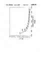
- FIG. 6is a graph representing deflection of the outer impact resisting layer relative to impact force vs. material thickness
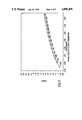
- FIG. 7is a graphical representation of force vs. spring rate for the energy dissipative layer.
- fan blade protection system 100laminately bonded to a fan blade 10.
- fan blade protection system 100is specifically directed to substantially preventing erosion by particulate impingement on fan blade 10.
- fan blade protection system 100is particularly useful in protecting aerodynamic surfaces formed with Fiberglas reinforced plastic-like materials. Additionally, fan blade protection system 100 has been designed to facilitate field application of fan blade protection system 100 to fan blade systems already in service.
- Composite fan blade 10is typically formed from a laminate structure comprising layers of Fiberglas and a thermoset resin to form a high strength, lightweight, and inexpensive fan element.
- the composite laminate structure of fan blade protection system 100comprises an erosion resistant outer layer 110 bonded to an elastomeric energy dissipative layer 120, the combination bonded to the outer surface of fan blade portion 12.
- elastomeric energy dissipative layer 120includes opposing surfaces 121 and 123, both of which having a pressure-sensitive adhesive coating for bonding to impact of erosion-resistant layer 110 and the outer surface of fan blade portion 12, respectively.
- an addition to the adhesive bondingis utilized to laminate impact or erosion resistant layer 110 and energy dissipative layer 120 to the fan blade portion 12.
- a plurality of rivet type fasteners 150are added through the plurality of the overlapping openings 112, 122, and 132. This additional fastening means adds an extra measure of safety, to insure that the fan blade protection system 100 will remain fixably coupled to fan blade 10 throughout its operable life.
- Fan blade 10represents a typical Fiberglas reinforced plastic blade used in fans having diameters which may range from 7 feet to 40 feet. Such fans are typically utilized in commercial water cooling towers, condensers, heat exchangers, and ventilation systems. Particulate impingement of the fan blades in these systems is predominantly in the form of water droplets. These droplets may have diameters which range in size up to 0.125 inches and impact the surface of the blade at a relative velocity in the order of 140 mph. As a means of protecting fan blade 10 from damage, the outer layer 110 must elastically deform upon impact with a high velocity water droplet. The energy transferred to outer layer 110 can then be dispensed over a large area of fan blade 10 by the elastomeric layer 120.
- the outer layer of fan blade protection system 100would require a minimum yield strength of 57,000 psi (pounds per square inch). From this minimum yield strength it is calculated that erosion resistant member 110 must have a yield strength of at least 190,000 psi to provide an adequate safety factor.
- impact resistant member 110is formed from 300 series stainless steel.
- the yield strength of 300 series stainless steelsare sufficient to allow erosion resistant member 110 to have a minimum thickness of 0.002".
- the maximum thickness for erosion resistant member 110is determined by the hand formability of the material. This maximum thickness has been determined empirically to be 0.004".
- erosion resistant member 110 formed from 304 stainless steel having a thickness of 0.003"has been successfully used.
- FIG. 6there is shown a graph of deflection vs. thickness of the 304 stainless steel erosion resistant layer, when impacted by a 0.125" water droplet at 140 mph.
- Graph line 200clearly shows the deflection dropping drastically between material thicknesses of 0.001" and 0.002", with less drastic deflection between 0.002" and 0.004", and further flattening out for thicknesses above 0.004". Therefore, hand forming does not create and design limitations on erosion resistant member 110, as thicker materials which would require other methods of application would not provide significant advantages to the functioning of fan blade protection system 100.
- the metallic erosion resistant member 110elastically deforms when impacted by high velocity water droplets and then springs back to its original position, its yield point not having been reached. As shown by graph line 200, a 140 mph water droplet causes the stainless steel outer layer to deflect 0.023 inches. Obviously, the outer layer 110 must be spaced at least that distance from the fan blade surface to prevent the total force of the impact from being transmitted directly to the blade surface at the point of impact. Because the impact area is small and the impact force over a greater surface area to prevent damage to the Fiberglas fibers of the composite fan blade structure.
- graph line 300represents the change in force vs. compressibility for the energy dissipative layer bonded to a 0.003" thick impact resistant member when impacted by a 140 mph 0.125 inch water droplet.
- the forceincreases almost linearly as the stiffness of the elastic foundation increases. It is therefore desirable to select an elastomeric material with a low spring rate so as to deliver the smallest possible force to any point on the surface of the blade.
- an energy dissipative layerhaving a spring rate in the range of 430-400 pounds per inch squared per inch, and a thickness approximating 0.045 inches has been successfully used.
- One such elastomeric energy dissipative layer materialis commercially available from Adhesives Research, Inc. of Glenrock, Pa., having the designation AR-5500.
- the metallic impact resistant member 110elastically deforms on impact, spreading the impact energy over the area of deformation, which is larger than the impacting droplet.
- the elastomeric energy dissipative member 120distributes the impact forces over an even larger area and dissipates a portion of the energy by means of its elastic compression.
- the force transferred to the surface of fan blade 10is spread over a large area and sufficiently low to not cause damage to the blade structure.
- the elastomeric energy dissipative layer 120is fabricated in the form of a double-coated foam bonding tape having an acrylic polymer adhesive or other environmentally resistant adhesive for bonding the composite structure of fan blade protection system 100 to fan blade 10.
- the method of assembly of fan blade protection system 100 to fan blade 10is relatively simple and straight forward, easily carried out in both manufacturing and repair environments.
- the stainless steel foil 110is overlaid on the elastomeric bonding tape surface 121 and pressed in contiguous contact therewith.
- the pressure applied to the foil 110 as it is applied to the bonding tape surface 121activates the adhesive for bonding each to the other.
- the laminated structure of the metallic coil 110 and the elastomeric tape 130is then bonded to the prepared fan blade portion 12, which is typically the leading edge of the aerodynamic fan blade 10.
- Foam bonding tape 120typically is fabricated with a removable liner over one adhesive surface, such as surface 123, which is removed prior to contact with the surface to which the tape is to be bonded. With this protective liner removed, a portion of the adhesively coated elastomeric tape surface 123 is pressed in contiguous contact with either the upper or lower exterior surface of leading edge 12. The remainder of the unadhered laminate structure 100 is then hand formed around the arcuate surface of leading edge 12 from one end of the blade to the other.
- fan blade protection system 100is secured to fan blade 10 by both adhesive bonding with an elastomeric tape 120 having adhesive on surfaces 121 and 123, in combination with the addition of fasteners 150.
- This redundant system for coupling the laminate structure 100 to fan blade 10may be utilized where high reliability and a long service life in a hostile environment is required.
- Fasteners 150may be a 5 mm nylon rivet which secures fan blade protection system 100 to fan blade 10 through a series of overlaying apertures 112, 122, and 132. Apertures 112, 122, and 132 in erosion resistant member 110, elastomeric tape 120, and fan blade 10 respectively may be either preformed prior to assembly or subsequent thereto.
- Non-metallic fan bladeshave found extensive use in fan systems which operate in corrosive environments. However, these fan blades are subject to erosion from impingement by particulates. These particulates in the form of water droplets, dust, and dirt, impact the blade, causing surface damage and eventually cause the underlying structural fibers to break, which leads to blade failure. Protection from this failure mechanism must not interfere with the aerodynamics of the fan blade nor significantly affect the fan's weight, so as not to adversely affect the fan system performance. Fan blade protection system 100 meets these requirements with a laminate structure comprising a metallic impact resistant member 110 bonded to an elastomeric energy dissipative member 120, this combination being bonded to the leading edge 12 of fan blade 10. The functioning of fan blade protection system 100 depends critically on the design parameters for each of the materials in the laminate structure.
- the erosion resistant layer 110in addition to being lightweight, corrosion resistant, and hand formable, must be of high yield strength. To function properly, the erosion resistant layer 110 must elastically deform during the expected worst cause particulate impingement. Therefore, a material having a yield strength of at least 190,000 psi is critical to the proper functioning of fan blade protection system 100.
- the erosion resistant layer 110be separated from the fan blade surface by an energy dissipative layer 120, meeting several critical design parameters as well.
- Energy dissipative layer 120must be sufficiently thick to prevent contact between the impact resistant layer 110 and the fan blade surface during deformation caused by particulate impingement. However, layer 120 cannot be too thick, so as to disturb the aerodynamics of the fan blade to which it is bonded.
- the spring rate of the elastic energy dissipative layer 120is another characteristic critical to the functioning of fan blade protection system 100.
- Energy dissipative layer 120must have a spring rate and thickness which provides sufficient resistance to deformation to prevent contact between erosion resistant layer 110 and the blade surface while dissipating and distributing the impact forces from the small area of impingement to a large fan blade surface area.
- these critical requirementshave been met by a copolymer foam having an approximate thickness of 0.045 inches with a spring rate having an approximating range of 430-440 psi.
- energy dissipative layer 120may be provided as a foam tape, adhesively coated on one or both surfaces to facilitate assembly of the laminate structure and bonding of that structure to the fan blade.
- a bonding agentcould be separately applied to the erosion resistant member 110 or the energy dissipative member 120 as well as between the laminate structure 100 and fan blade 10, at the time of assembly.
- fan blade protection system 100When fan blade protection system 100 is applied to fan systems which require maintenance personnel to handle the protected fan blades, such as during routine cleaning, then it is necessary to prevent contact with the thin metallic edge of impact resistant member 110. As shown in the embodiment of FIG. 3, contact with the edge of metallic impact resistant member 110 is prevented by an extension 124 of energy dissipative member 120. During contact between maintenance personnel and fan blade protection system 100, metallic impact resistant member 110 deforms, the edge being displaced below the surface of extension 124. When maintenance personnel are in transverse sliding contact with the laminate structure of system 100, a portion of extension 124, in shear, elastically displaces to cover the edge of metallic impact resistant member 110.
- FIG. 3Athere is shown an alternate embodiment for fan blade protection system 100 wherein the terminating edge of the laminate structure is provided with a fillet 140 of caulking material, such as a silicone adhesive/sealant.
- Fillet 140serves to prevent injurious contact by maintenance personnel with the thin metallic edge of impact resistant member 110. Additionally, fillet 140 provides a smooth transition between the outer surface of fan blade protection system 100 and the surface of fan blade 10.
- the large fan blades to which fan blade protection system 100 is appliedhave complex aerodynamic shapes. Typically, the blades change in pitch as a function of their radial distance along the length of the blade. Thus, the leading edge of the blade tends to have a helical twist to which fan blade protection system 100 must conform.
- elastomeric energy absorbing member 120may be provided with a plurality of uniformly spaced slits, as shown in FIG. 4.
- the plurality of slits 126extend from the longitudinal edge 125 of layer 120 a predetermined distance toward the opposing edge 127.
- a plurality of uniformly spaced slits 128extend from the longitudinal edge 127 a predetermined distance toward the opposing edge 125.
- Each of slits 126 or 128may extend a dimension up to approximately one-third the distance between edges 125 and 127.
- slits 126 and 128are longitudinally aligned and equally spaced across the length of layer 120.
- FIG. 5shows an alternate embodiment for layer 120 wherein the slits 126 and 128 are provided in a longitudinally staggered relationship.
- slits 126 and 128may extend from longitudinal edges 125 and 127, respectively, a greater distance than possible with the embodiment of FIG. 4.
- Slits 126 and 128may extend a dimension equal to approximately two-thirds the distance between edges 125 and 127.
- the slits provided in the embodiments of FIG. 4 and FIG. 5provide sufficient space to allow the necessary material displacement required for contiguous interface between fan blade protection system 100 and the longitudinal contour of fan blade 10 without causing creasing or buckling of any portion of fan blade protection system 100.
Landscapes
- Engineering & Computer Science (AREA)
- Mechanical Engineering (AREA)
- General Engineering & Computer Science (AREA)
- Structures Of Non-Positive Displacement Pumps (AREA)
Abstract
Description
Claims (20)
Priority Applications (1)
| Application Number | Priority Date | Filing Date | Title |
|---|---|---|---|
| US07/208,098US4895491A (en) | 1988-06-17 | 1988-06-17 | Fan blade protection system |
Applications Claiming Priority (1)
| Application Number | Priority Date | Filing Date | Title |
|---|---|---|---|
| US07/208,098US4895491A (en) | 1988-06-17 | 1988-06-17 | Fan blade protection system |
Publications (1)
| Publication Number | Publication Date |
|---|---|
| US4895491Atrue US4895491A (en) | 1990-01-23 |
Family
ID=22773169
Family Applications (1)
| Application Number | Title | Priority Date | Filing Date |
|---|---|---|---|
| US07/208,098Expired - Fee RelatedUS4895491A (en) | 1988-06-17 | 1988-06-17 | Fan blade protection system |
Country Status (1)
| Country | Link |
|---|---|
| US (1) | US4895491A (en) |
Cited By (59)
| Publication number | Priority date | Publication date | Assignee | Title |
|---|---|---|---|---|
| WO1992002731A1 (en)* | 1990-07-27 | 1992-02-20 | The Marley Cooling Tower Company | Fan blade having abrasion resistant leading edge |
| US5165859A (en)* | 1992-06-26 | 1992-11-24 | Hudson Products Corporation | Leading edge protection for fan blade |
| US5210946A (en)* | 1992-06-26 | 1993-05-18 | Hudson Products Corporation | Leading edge protection for fan blade |
| US5486096A (en)* | 1994-06-30 | 1996-01-23 | United Technologies Corporation | Erosion resistant surface protection |
| US5542820A (en)* | 1994-12-23 | 1996-08-06 | United Technologies Corporation | Engineered ceramic components for the leading edge of a helicopter rotor blade |
| WO1998031938A1 (en)* | 1997-01-17 | 1998-07-23 | ABB Fläkt Oy | Evaporating fan and its blade wheel |
| US5876651A (en)* | 1996-05-29 | 1999-03-02 | United Technologies Corporation | Method for forming a composite structure |
| US6340288B1 (en) | 1997-01-17 | 2002-01-22 | Abb Flakt Oy | High-pressure fan |
| US6578265B2 (en)* | 1998-12-17 | 2003-06-17 | Eurocopter | Method of hot peeling for removing a blade leading edge cap |
| US20050037685A1 (en)* | 2003-08-12 | 2005-02-17 | Mattel, Inc. | Airfoil blade with cushioned edge for powered toy aircraft |
| US20060192054A1 (en)* | 2004-10-13 | 2006-08-31 | Lachenmeier Timothy T | Inflatable and deployable systems with three dimensionally reinforced membranes |
| US20080087768A1 (en)* | 2006-06-14 | 2008-04-17 | Airbus Uk Limited | Aircraft component |
| US20080265095A1 (en)* | 2007-04-24 | 2008-10-30 | The Boeing Company | Energy absorbing impact band and method |
| US20080308669A1 (en)* | 2006-06-14 | 2008-12-18 | Airbus Uk Limited | composite aircraft component |
| US20090053067A1 (en)* | 2007-07-23 | 2009-02-26 | General Electric Company | Airfoil and method for protecting airfoil leading edge |
| EP2037082A1 (en)* | 2007-09-13 | 2009-03-18 | Snecma | Damping device for a composite blade |
| US20090087314A1 (en)* | 2006-06-09 | 2009-04-02 | Michael Drachmann Haag | Wind Turbine Blade And A Pitch Controlled Wind Turbine |
| US20100028160A1 (en)* | 2008-07-31 | 2010-02-04 | General Electric Company | Compressor blade leading edge shim and related method |
| US20100054945A1 (en)* | 2008-08-28 | 2010-03-04 | Rolls-Royce Plc. | Aerofoil |
| EP2189625A1 (en)* | 2008-11-24 | 2010-05-26 | Rolls-Royce Deutschland Ltd & Co KG | Hybrid component for a gas-turbine engine |
| US20100126662A1 (en)* | 2008-11-25 | 2010-05-27 | Rolls-Royce Deutschland Ltd & Co Kg | Method for the manufacture of hybrid components for aircraft gas turbines |
| US20100232974A1 (en)* | 2009-03-12 | 2010-09-16 | Snecma | Blade made of composite material comprising a damping device |
| US20110033308A1 (en)* | 2009-08-07 | 2011-02-10 | Huth Brian P | Titanium sheath and airfoil assembly |
| US20110058950A1 (en)* | 2009-08-06 | 2011-03-10 | Nitto Denko Corporation | Protecting film for blade of wind power generator |
| US20110116906A1 (en)* | 2009-11-17 | 2011-05-19 | Smith Blair A | Airfoil component wear indicator |
| US20110206529A1 (en)* | 2010-12-10 | 2011-08-25 | General Electric Company | Spar assembly for a wind turbine rotor blade |
| US20110243751A1 (en)* | 2011-01-28 | 2011-10-06 | General Electric Company | Wind turbine blades with a hardened substrate construction |
| WO2012009037A3 (en)* | 2010-06-22 | 2012-03-08 | Sikorsky Aircraft Corporation | Erosion resistant helicopter blade |
| WO2012035008A3 (en)* | 2010-09-16 | 2012-05-24 | Grundfos Holding A/S | Axial flow impeller |
| CN102792017A (en)* | 2011-01-26 | 2012-11-21 | 藤仓橡胶工业株式会社 | Blade and protective laminated sheet for blade |
| EP2130762A3 (en)* | 2008-05-06 | 2013-01-23 | Alenia Aeronautica S.p.A. | Wing and empennage leading edge structure made of thermoplastic material with a stiffened double-shell configuration |
| CN102927048A (en)* | 2011-08-12 | 2013-02-13 | 林海山 | Telescopic fan blade |
| US20130045105A1 (en)* | 2011-08-17 | 2013-02-21 | Howard Daniel Driver | Wind turbine blade and method of protecting the same |
| DE102013218743A1 (en) | 2012-11-30 | 2014-06-05 | Deutsches Zentrum für Luft- und Raumfahrt e.V. | Supporting structure for vehicle e.g. car, and wind power plant, has load distribution element that is located between covering portion and structural element, for distribution of working force acting on structural element |
| US8834126B2 (en) | 2011-06-30 | 2014-09-16 | United Technologies Corporation | Fan blade protection system |
| US20160177969A1 (en)* | 2014-12-19 | 2016-06-23 | Rolls-Royce Deutschland Ltd & Co Kg | Compressor blade of a gas turbine |
| EP3067519A1 (en)* | 2015-03-04 | 2016-09-14 | Rolls-Royce Deutschland Ltd & Co KG | Fan blade for a flight drive |
| EP3144525A1 (en)* | 2015-09-16 | 2017-03-22 | Siemens Aktiengesellschaft | Wind turbine rotor blade and thick leading edge shell |
| US9605651B2 (en) | 2013-12-04 | 2017-03-28 | General Electric Company | Spar assembly for a wind turbine rotor blade |
| US9790919B2 (en) | 2014-02-25 | 2017-10-17 | General Electric Company | Joint assembly for rotor blade segments of a wind turbine |
| US20180010614A1 (en)* | 2016-07-07 | 2018-01-11 | General Electric Company | Non-newtonian materials in aircraft engine airfoils |
| WO2018059763A1 (en)* | 2016-09-30 | 2018-04-05 | Siemens Aktiengesellschaft | Protective cap for protecting a leading edge of a wind turbine rotor blade |
| CN108474258A (en)* | 2015-12-21 | 2018-08-31 | 赛峰航空器发动机 | Main edge shield |
| US20180274374A1 (en)* | 2015-09-28 | 2018-09-27 | Safran Aircraft Engines | Blade comprising a leading edge shield and method for producing the blade |
| WO2020021199A1 (en)* | 2018-07-24 | 2020-01-30 | Safran Aircraft Engines | Turbine blade having a structural reinforcement with enhanced adherence |
| US10556701B2 (en)* | 2017-04-14 | 2020-02-11 | Rohr, Inc. | Bird-strike energy absorbing net |
| US10563636B2 (en) | 2017-08-07 | 2020-02-18 | General Electric Company | Joint assembly for a wind turbine rotor blade |
| EP3620648A1 (en)* | 2018-09-10 | 2020-03-11 | Siemens Gamesa Renewable Energy A/S | Method of providing an edge seal for a rotor blade add-on |
| EP3513060B1 (en) | 2016-09-13 | 2020-03-11 | Polytech A/S | Wind turbine blade including protective cover |
| US10677068B2 (en)* | 2018-01-18 | 2020-06-09 | Raytheon Technologies Corporation | Fan blade with filled pocket |
| WO2021160609A1 (en)* | 2020-02-10 | 2021-08-19 | Lm Wind Power A/S | Leading edge protection for a wind turbine blade |
| EP3913213A1 (en)* | 2020-05-22 | 2021-11-24 | Mitsubishi Heavy Industries, Ltd. | Windmill blade, windmill, and method of manufacturing windmill blade |
| CN113843933A (en)* | 2021-08-24 | 2021-12-28 | 株洲时代新材料科技股份有限公司 | Manufacturing method of edge covering for composite material blade, product and composite material blade |
| US11312507B2 (en)* | 2019-09-03 | 2022-04-26 | The Boeing Company | Repair assembly to repair an area on a member of a vehicle |
| US11333127B2 (en)* | 2018-03-08 | 2022-05-17 | Siemens Gamesa Renewable Energy A/S | Protective cover for protecting a leading edge of a wind turbine blade |
| US20220154685A1 (en)* | 2019-03-08 | 2022-05-19 | Siemens Gamesa Renewable Energy A/S | Method of shaping an edge seal for a rotor blade add-on |
| WO2022144240A1 (en)* | 2020-12-28 | 2022-07-07 | Blade Dynamics Limited | Protective cap for a leading edge of a wind turbine blade |
| CN115324931A (en)* | 2021-05-11 | 2022-11-11 | 中国航发商用航空发动机有限责任公司 | Fan blade, fan rotor subassembly and aeroengine |
| EP4311764A1 (en)* | 2022-07-25 | 2024-01-31 | Airbus Operations GmbH | Aerodynamic structure and aircraft |
Citations (10)
| Publication number | Priority date | Publication date | Assignee | Title |
|---|---|---|---|---|
| SU284623A1 (en)* | AIR SCREW | |||
| FR505912A (en)* | 1919-11-10 | 1920-08-10 | Paulin Jean Pierre Ratier | Wooden aerial propeller on board armed |
| US1842178A (en)* | 1930-02-15 | 1932-01-19 | Westinghouse Electric & Mfg Co | Propeller |
| DE697349C (en)* | 1936-07-25 | 1940-10-11 | Hugo Heine | Edge protection for propeller blades |
| US2431184A (en)* | 1943-09-23 | 1947-11-18 | United Aireraft Corp | Composite blade |
| US4097193A (en)* | 1975-12-24 | 1978-06-27 | Messerschmitt-Boelkow-Blohm Gmbh | Elastomeric damping arrangement |
| GB2039526A (en)* | 1978-12-14 | 1980-08-13 | British Aerospace | Electroplating on rubber or rubber-like materials |
| US4667906A (en)* | 1985-04-02 | 1987-05-26 | Grumman Aerospace Corporation | Replaceable tip for aircraft leading edge |
| US4728262A (en)* | 1986-01-22 | 1988-03-01 | Textron Inc. | Erosion resistant propellers |
| US4738594A (en)* | 1986-02-05 | 1988-04-19 | Ishikawajima-Harima Jukogyo Kabushiki Kaisha | Blades for axial fans |
- 1988
- 1988-06-17USUS07/208,098patent/US4895491A/ennot_activeExpired - Fee Related
Patent Citations (11)
| Publication number | Priority date | Publication date | Assignee | Title |
|---|---|---|---|---|
| SU284623A1 (en)* | AIR SCREW | |||
| SU163896A1 (en)* | ||||
| FR505912A (en)* | 1919-11-10 | 1920-08-10 | Paulin Jean Pierre Ratier | Wooden aerial propeller on board armed |
| US1842178A (en)* | 1930-02-15 | 1932-01-19 | Westinghouse Electric & Mfg Co | Propeller |
| DE697349C (en)* | 1936-07-25 | 1940-10-11 | Hugo Heine | Edge protection for propeller blades |
| US2431184A (en)* | 1943-09-23 | 1947-11-18 | United Aireraft Corp | Composite blade |
| US4097193A (en)* | 1975-12-24 | 1978-06-27 | Messerschmitt-Boelkow-Blohm Gmbh | Elastomeric damping arrangement |
| GB2039526A (en)* | 1978-12-14 | 1980-08-13 | British Aerospace | Electroplating on rubber or rubber-like materials |
| US4667906A (en)* | 1985-04-02 | 1987-05-26 | Grumman Aerospace Corporation | Replaceable tip for aircraft leading edge |
| US4728262A (en)* | 1986-01-22 | 1988-03-01 | Textron Inc. | Erosion resistant propellers |
| US4738594A (en)* | 1986-02-05 | 1988-04-19 | Ishikawajima-Harima Jukogyo Kabushiki Kaisha | Blades for axial fans |
Cited By (115)
| Publication number | Priority date | Publication date | Assignee | Title |
|---|---|---|---|---|
| WO1992002731A1 (en)* | 1990-07-27 | 1992-02-20 | The Marley Cooling Tower Company | Fan blade having abrasion resistant leading edge |
| US5123814A (en)* | 1990-07-27 | 1992-06-23 | The Marley Cooling Tower Company | Industrial cooling tower fan blade having abrasion resistant leading edge |
| US5165859A (en)* | 1992-06-26 | 1992-11-24 | Hudson Products Corporation | Leading edge protection for fan blade |
| US5210946A (en)* | 1992-06-26 | 1993-05-18 | Hudson Products Corporation | Leading edge protection for fan blade |
| EP0576117A1 (en)* | 1992-06-26 | 1993-12-29 | Hudson Products Corporation | Edge protection for a fan blade |
| AU647330B2 (en)* | 1992-06-26 | 1994-03-17 | Hudson Products Corporation | Leading edge protection for fan blade |
| US5486096A (en)* | 1994-06-30 | 1996-01-23 | United Technologies Corporation | Erosion resistant surface protection |
| US5542820A (en)* | 1994-12-23 | 1996-08-06 | United Technologies Corporation | Engineered ceramic components for the leading edge of a helicopter rotor blade |
| US5876651A (en)* | 1996-05-29 | 1999-03-02 | United Technologies Corporation | Method for forming a composite structure |
| WO1998031938A1 (en)* | 1997-01-17 | 1998-07-23 | ABB Fläkt Oy | Evaporating fan and its blade wheel |
| US6264430B1 (en) | 1997-01-17 | 2001-07-24 | Abb Flakt Oy | Evaporating fan and its blade wheel |
| US6340288B1 (en) | 1997-01-17 | 2002-01-22 | Abb Flakt Oy | High-pressure fan |
| US6578265B2 (en)* | 1998-12-17 | 2003-06-17 | Eurocopter | Method of hot peeling for removing a blade leading edge cap |
| US20050037685A1 (en)* | 2003-08-12 | 2005-02-17 | Mattel, Inc. | Airfoil blade with cushioned edge for powered toy aircraft |
| US6960112B2 (en) | 2003-08-12 | 2005-11-01 | Mattel, Inc. | Airfoil blade with cushioned edge for powered toy aircraft |
| WO2006137909A3 (en)* | 2004-10-13 | 2009-04-09 | Gssl Inc | Inflatable and deployable systems with three dimensionally reinforced membranes |
| US20060192054A1 (en)* | 2004-10-13 | 2006-08-31 | Lachenmeier Timothy T | Inflatable and deployable systems with three dimensionally reinforced membranes |
| US20120189444A1 (en)* | 2006-06-09 | 2012-07-26 | Vestas Wind Systems A/S | Wind turbine blade and a pitch controlled wind turbine |
| EP2027390B2 (en)† | 2006-06-09 | 2020-07-01 | Vestas Wind Systems A/S | A wind turbine blade and a pitch controlled wind turbine |
| US8678746B2 (en)* | 2006-06-09 | 2014-03-25 | Vestas Wind Systems A/S | Wind turbine blade and a pitch controlled wind turbine |
| US20090087314A1 (en)* | 2006-06-09 | 2009-04-02 | Michael Drachmann Haag | Wind Turbine Blade And A Pitch Controlled Wind Turbine |
| US8162590B2 (en)* | 2006-06-09 | 2012-04-24 | Vestas Wind Systems A/S | Wind turbine blade and a pitch controlled wind turbine |
| US7942368B2 (en) | 2006-06-14 | 2011-05-17 | Airbus Operations Limited | Composite aircraft component |
| US8276846B2 (en) | 2006-06-14 | 2012-10-02 | Airbus Operations Limited | Aircraft component |
| US20080308669A1 (en)* | 2006-06-14 | 2008-12-18 | Airbus Uk Limited | composite aircraft component |
| US20080087768A1 (en)* | 2006-06-14 | 2008-04-17 | Airbus Uk Limited | Aircraft component |
| US7866605B2 (en)* | 2007-04-24 | 2011-01-11 | The Boeing Company | Energy absorbing impact band and method |
| US8066222B2 (en)* | 2007-04-24 | 2011-11-29 | The Boeing Company | Energy absorbing impact band |
| US20110095131A1 (en)* | 2007-04-24 | 2011-04-28 | The Boeing Company | Energy absorbing impact band |
| US20080265095A1 (en)* | 2007-04-24 | 2008-10-30 | The Boeing Company | Energy absorbing impact band and method |
| US20090053067A1 (en)* | 2007-07-23 | 2009-02-26 | General Electric Company | Airfoil and method for protecting airfoil leading edge |
| US7789630B2 (en)* | 2007-07-23 | 2010-09-07 | General Electric Company | Airfoil and method for protecting airfoil leading edge |
| FR2921099A1 (en)* | 2007-09-13 | 2009-03-20 | Snecma Sa | DAMPING DEVICE FOR DRAWINGS OF COMPOSITE MATERIAL |
| US8061997B2 (en) | 2007-09-13 | 2011-11-22 | Snecma | Damping device for composite blade |
| CN101387205B (en)* | 2007-09-13 | 2015-02-04 | 斯奈克玛 | Damping device for a composite blade |
| EP2037082A1 (en)* | 2007-09-13 | 2009-03-18 | Snecma | Damping device for a composite blade |
| US20090074586A1 (en)* | 2007-09-13 | 2009-03-19 | Snecma | Damping device for composite blade |
| RU2498083C2 (en)* | 2007-09-13 | 2013-11-10 | Снекма | Blade of composite material, compressor of gas turbine engine comprising such blade and turbojet engine |
| EP2130762A3 (en)* | 2008-05-06 | 2013-01-23 | Alenia Aeronautica S.p.A. | Wing and empennage leading edge structure made of thermoplastic material with a stiffened double-shell configuration |
| US20100028160A1 (en)* | 2008-07-31 | 2010-02-04 | General Electric Company | Compressor blade leading edge shim and related method |
| US8459955B2 (en)* | 2008-08-28 | 2013-06-11 | Rolls-Royce Plc | Aerofoil |
| US20100054945A1 (en)* | 2008-08-28 | 2010-03-04 | Rolls-Royce Plc. | Aerofoil |
| EP2189625A1 (en)* | 2008-11-24 | 2010-05-26 | Rolls-Royce Deutschland Ltd & Co KG | Hybrid component for a gas-turbine engine |
| US20100129651A1 (en)* | 2008-11-24 | 2010-05-27 | Rolls-Royce Deutschland Ltd & Co Kg | Hybrid component for a gas-turbine engine |
| US9126361B2 (en) | 2008-11-25 | 2015-09-08 | Rolls-Royce Deutschland Ltd & Co Kg | Method for the manufacture of hybrid components for aircraft gas turbines |
| US20100126662A1 (en)* | 2008-11-25 | 2010-05-27 | Rolls-Royce Deutschland Ltd & Co Kg | Method for the manufacture of hybrid components for aircraft gas turbines |
| US8500410B2 (en)* | 2009-03-12 | 2013-08-06 | Snecma | Blade made of composite material comprising a damping device |
| US20100232974A1 (en)* | 2009-03-12 | 2010-09-16 | Snecma | Blade made of composite material comprising a damping device |
| US20110058950A1 (en)* | 2009-08-06 | 2011-03-10 | Nitto Denko Corporation | Protecting film for blade of wind power generator |
| US20130243605A1 (en)* | 2009-08-06 | 2013-09-19 | Nitto Denko Corporation | Protecting film for blade of wind power generator |
| US8814527B2 (en)* | 2009-08-07 | 2014-08-26 | Hamilton Sundstrand Corporation | Titanium sheath and airfoil assembly |
| US20110033308A1 (en)* | 2009-08-07 | 2011-02-10 | Huth Brian P | Titanium sheath and airfoil assembly |
| US20110116906A1 (en)* | 2009-11-17 | 2011-05-19 | Smith Blair A | Airfoil component wear indicator |
| EP2322427B2 (en)† | 2009-11-17 | 2020-07-29 | Hamilton Sundstrand Corporation | Airfoil assembly and airfoil assembly wear indicating method |
| EP2322427B1 (en) | 2009-11-17 | 2017-06-14 | Hamilton Sundstrand Corporation | Airfoil assembly and airfoil assembly wear indicating method |
| US9429025B2 (en) | 2010-06-22 | 2016-08-30 | Sikorsky Aircraft Corporation | Erosion resistant helicopter blade |
| WO2012009037A3 (en)* | 2010-06-22 | 2012-03-08 | Sikorsky Aircraft Corporation | Erosion resistant helicopter blade |
| US9435349B2 (en) | 2010-09-16 | 2016-09-06 | Grundfos Holding A/S | Axial flow impeller |
| WO2012035008A3 (en)* | 2010-09-16 | 2012-05-24 | Grundfos Holding A/S | Axial flow impeller |
| US20110206529A1 (en)* | 2010-12-10 | 2011-08-25 | General Electric Company | Spar assembly for a wind turbine rotor blade |
| US8186964B2 (en)* | 2010-12-10 | 2012-05-29 | General Electric Company | Spar assembly for a wind turbine rotor blade |
| US8770942B2 (en)* | 2011-01-26 | 2014-07-08 | Fujikura Rubber Ltd | Blade and laminated protective sheet for the blade |
| US20130101426A1 (en)* | 2011-01-26 | 2013-04-25 | Fujikura Rubber Ltd | Blade and laminated protective sheet for the blade |
| CN102792017B (en)* | 2011-01-26 | 2014-12-10 | 藤仓橡胶工业株式会社 | Blade and protective laminated sheet for blade |
| CN102792017A (en)* | 2011-01-26 | 2012-11-21 | 藤仓橡胶工业株式会社 | Blade and protective laminated sheet for blade |
| US20110243751A1 (en)* | 2011-01-28 | 2011-10-06 | General Electric Company | Wind turbine blades with a hardened substrate construction |
| US8425196B2 (en)* | 2011-01-28 | 2013-04-23 | General Electric Company | Wind turbine blades with a hardened substrate construction |
| US8834126B2 (en) | 2011-06-30 | 2014-09-16 | United Technologies Corporation | Fan blade protection system |
| CN102927048A (en)* | 2011-08-12 | 2013-02-13 | 林海山 | Telescopic fan blade |
| US20130045105A1 (en)* | 2011-08-17 | 2013-02-21 | Howard Daniel Driver | Wind turbine blade and method of protecting the same |
| DE102013218743B4 (en) | 2012-11-30 | 2018-08-30 | Deutsches Zentrum für Luft- und Raumfahrt e.V. | vehicle |
| DE102013218743A1 (en) | 2012-11-30 | 2014-06-05 | Deutsches Zentrum für Luft- und Raumfahrt e.V. | Supporting structure for vehicle e.g. car, and wind power plant, has load distribution element that is located between covering portion and structural element, for distribution of working force acting on structural element |
| US9605651B2 (en) | 2013-12-04 | 2017-03-28 | General Electric Company | Spar assembly for a wind turbine rotor blade |
| US9790919B2 (en) | 2014-02-25 | 2017-10-17 | General Electric Company | Joint assembly for rotor blade segments of a wind turbine |
| US20160177969A1 (en)* | 2014-12-19 | 2016-06-23 | Rolls-Royce Deutschland Ltd & Co Kg | Compressor blade of a gas turbine |
| US9964117B2 (en)* | 2014-12-19 | 2018-05-08 | Rolls-Royce Deutschland Ltd & Co Kg | Compressor blade of a gas turbine |
| EP3067519A1 (en)* | 2015-03-04 | 2016-09-14 | Rolls-Royce Deutschland Ltd & Co KG | Fan blade for a flight drive |
| US10125616B2 (en) | 2015-03-04 | 2018-11-13 | Rolls-Royce Deutschland Ltd & Co Kg | Fan blade for an aircraft engine |
| EP3144525A1 (en)* | 2015-09-16 | 2017-03-22 | Siemens Aktiengesellschaft | Wind turbine rotor blade and thick leading edge shell |
| US11105210B2 (en)* | 2015-09-28 | 2021-08-31 | Safran Aircraft Engines | Blade comprising a leading edge shield and method for producing the blade |
| US20180274374A1 (en)* | 2015-09-28 | 2018-09-27 | Safran Aircraft Engines | Blade comprising a leading edge shield and method for producing the blade |
| JP2018538481A (en)* | 2015-12-21 | 2018-12-27 | サフラン・エアクラフト・エンジンズ | Leading edge shield |
| EP3394397B1 (en) | 2015-12-21 | 2019-10-02 | Safran Aircraft Engines | Leading edge sheath |
| EP3394397B2 (en)† | 2015-12-21 | 2022-08-10 | Safran Aircraft Engines | Leading edge sheath |
| US10934851B2 (en)* | 2015-12-21 | 2021-03-02 | Safran Aircraft Engines | Leading edge shield |
| CN108474258A (en)* | 2015-12-21 | 2018-08-31 | 赛峰航空器发动机 | Main edge shield |
| US10371097B2 (en)* | 2016-07-07 | 2019-08-06 | General Electric Company | Non-Newtonian materials in aircraft engine airfoils |
| US20180010614A1 (en)* | 2016-07-07 | 2018-01-11 | General Electric Company | Non-newtonian materials in aircraft engine airfoils |
| US10907618B2 (en) | 2016-09-13 | 2021-02-02 | Polytech A/S | Wind turbine blade including protective cover |
| EP3513060B1 (en) | 2016-09-13 | 2020-03-11 | Polytech A/S | Wind turbine blade including protective cover |
| WO2018059763A1 (en)* | 2016-09-30 | 2018-04-05 | Siemens Aktiengesellschaft | Protective cap for protecting a leading edge of a wind turbine rotor blade |
| US10556701B2 (en)* | 2017-04-14 | 2020-02-11 | Rohr, Inc. | Bird-strike energy absorbing net |
| US10563636B2 (en) | 2017-08-07 | 2020-02-18 | General Electric Company | Joint assembly for a wind turbine rotor blade |
| US10677068B2 (en)* | 2018-01-18 | 2020-06-09 | Raytheon Technologies Corporation | Fan blade with filled pocket |
| US11333127B2 (en)* | 2018-03-08 | 2022-05-17 | Siemens Gamesa Renewable Energy A/S | Protective cover for protecting a leading edge of a wind turbine blade |
| US11555406B2 (en)* | 2018-07-24 | 2023-01-17 | Safran Aircraft Engines | Turbine blade having a structural reinforcement with enhanced adherence |
| FR3084400A1 (en)* | 2018-07-24 | 2020-01-31 | Safran Aircraft Engines | BLADE OF TURBOMACHINE COMPRISING A STRUCTURAL REINFORCEMENT WITH REINFORCED ADHESION |
| WO2020021199A1 (en)* | 2018-07-24 | 2020-01-30 | Safran Aircraft Engines | Turbine blade having a structural reinforcement with enhanced adherence |
| US20210293152A1 (en)* | 2018-07-24 | 2021-09-23 | Safran Aircraft Engines | Turbine blade having a structural reinforcement with enhanced adherence |
| WO2020052939A1 (en)* | 2018-09-10 | 2020-03-19 | Siemens Gamesa Renewable Energy A/S | Method of providing an edge seal for a rotor blade add-on |
| US11454209B2 (en) | 2018-09-10 | 2022-09-27 | Siemens Gamesa Renewable Energy A/S | Method of providing an edge seal for a rotor blade add-on |
| EP3620648A1 (en)* | 2018-09-10 | 2020-03-11 | Siemens Gamesa Renewable Energy A/S | Method of providing an edge seal for a rotor blade add-on |
| US20220154685A1 (en)* | 2019-03-08 | 2022-05-19 | Siemens Gamesa Renewable Energy A/S | Method of shaping an edge seal for a rotor blade add-on |
| US11939947B2 (en)* | 2019-03-08 | 2024-03-26 | Siemens Gamesa Renewable Energy A/S | Method of shaping an edge seal for a rotor blade add-on |
| US11312507B2 (en)* | 2019-09-03 | 2022-04-26 | The Boeing Company | Repair assembly to repair an area on a member of a vehicle |
| WO2021160609A1 (en)* | 2020-02-10 | 2021-08-19 | Lm Wind Power A/S | Leading edge protection for a wind turbine blade |
| US11976626B2 (en) | 2020-02-10 | 2024-05-07 | Lm Wind Power A/S | Leading edge protection for a wind turbine blade |
| EP4397854A3 (en)* | 2020-02-10 | 2024-10-02 | LM Wind Power A/S | Leading edge protection for a wind turbine blade |
| EP3913213A1 (en)* | 2020-05-22 | 2021-11-24 | Mitsubishi Heavy Industries, Ltd. | Windmill blade, windmill, and method of manufacturing windmill blade |
| US12018640B2 (en) | 2020-05-22 | 2024-06-25 | Mitsubishi Heavy Industries, Ltd. | Windmill blade, windmill, and method of manufacturing windmill blade |
| WO2022144240A1 (en)* | 2020-12-28 | 2022-07-07 | Blade Dynamics Limited | Protective cap for a leading edge of a wind turbine blade |
| CN115324931A (en)* | 2021-05-11 | 2022-11-11 | 中国航发商用航空发动机有限责任公司 | Fan blade, fan rotor subassembly and aeroengine |
| CN115324931B (en)* | 2021-05-11 | 2024-01-30 | 中国航发商用航空发动机有限责任公司 | Fan blade, fan rotor assembly and aeroengine |
| CN113843933A (en)* | 2021-08-24 | 2021-12-28 | 株洲时代新材料科技股份有限公司 | Manufacturing method of edge covering for composite material blade, product and composite material blade |
| EP4311764A1 (en)* | 2022-07-25 | 2024-01-31 | Airbus Operations GmbH | Aerodynamic structure and aircraft |
Similar Documents
| Publication | Publication Date | Title |
|---|---|---|
| US4895491A (en) | Fan blade protection system | |
| US10791787B2 (en) | Local energy absorber | |
| US9206706B2 (en) | Turbomachine casing assembly | |
| US8434716B2 (en) | Compliant crown panel for an aircraft | |
| EP2004490B1 (en) | Lightning protection system for composite structure | |
| EP1963095B1 (en) | Protection device | |
| US7866605B2 (en) | Energy absorbing impact band and method | |
| EP0730951B1 (en) | A composite laminate | |
| CA2407977C (en) | Composite material for armour plating | |
| EP2457821B1 (en) | Compliant panel for aircraft | |
| US7575417B2 (en) | Reinforced fan blade | |
| US7121758B2 (en) | Joint arrangement | |
| US20050169763A1 (en) | Helicopter rotor and method of repairing same | |
| JPS62255297A (en) | Fender device | |
| EP2620654B1 (en) | A turbomachine casing assembly with blade containment cavity | |
| GB2451797A (en) | Impact-absorbing structural component | |
| US7565778B2 (en) | Composite protection for revealing damage to a core in a vehicle such as an aircraft | |
| CN215670233U (en) | Friction compound type buckling restrained brace | |
| US20120040159A1 (en) | Structural composite panel for an aircraft including a protection against high energy impacts | |
| US20080308669A1 (en) | composite aircraft component | |
| DE102011101303A1 (en) | Impact protection plate for vehicles, in particular aircraft | |
| EP0872417A1 (en) | Hybrid deicer | |
| EP2620653B1 (en) | A turbomachine casing assembly with blade containment cavity | |
| US20200391880A1 (en) | Machinable molded fretting buffer | |
| US20190300167A1 (en) | Erosion protection system |
Legal Events
| Date | Code | Title | Description |
|---|---|---|---|
| AS | Assignment | Owner name:ENVIRONMENTAL ELEMENTS CORPORATION, P.O. BOX 1318, Free format text:ASSIGNMENT OF ASSIGNORS INTEREST.;ASSIGNORS:CROSS, STEVEN R.;PASS, STUART J.;HUNTINGTON, ROBERT G.;REEL/FRAME:004941/0597 Effective date:19880715 Owner name:ENVIRONMENTAL ELEMENTS CORPORATION, A CORP. OF MD, Free format text:ASSIGNMENT OF ASSIGNORS INTEREST;ASSIGNORS:CROSS, STEVEN R.;PASS, STUART J.;HUNTINGTON, ROBERT G.;REEL/FRAME:004941/0597 Effective date:19880715 | |
| FEPP | Fee payment procedure | Free format text:PAYOR NUMBER ASSIGNED (ORIGINAL EVENT CODE: ASPN); ENTITY STATUS OF PATENT OWNER: SMALL ENTITY | |
| FPAY | Fee payment | Year of fee payment:4 | |
| REMI | Maintenance fee reminder mailed | ||
| FPAY | Fee payment | Year of fee payment:8 | |
| SULP | Surcharge for late payment | ||
| AS | Assignment | Owner name:MERCANTILE-SAFE DEPOSIT AND TRUST COMPANY, MARYLAN Free format text:ASSIGNMENT OF ASSIGNORS INTEREST;ASSIGNOR:ENVIRONMENTAL ELEMENTS CORPORATION;REEL/FRAME:011044/0516 Effective date:20000630 | |
| REMI | Maintenance fee reminder mailed | ||
| LAPS | Lapse for failure to pay maintenance fees | ||
| STCH | Information on status: patent discontinuation | Free format text:PATENT EXPIRED DUE TO NONPAYMENT OF MAINTENANCE FEES UNDER 37 CFR 1.362 | |
| FP | Lapsed due to failure to pay maintenance fee | Effective date:20020123 |