US4895164A - Infrared clinical thermometer - Google Patents
Infrared clinical thermometerDownload PDFInfo
- Publication number
- US4895164A US4895164AUS07/244,738US24473888AUS4895164AUS 4895164 AUS4895164 AUS 4895164AUS 24473888 AUS24473888 AUS 24473888AUS 4895164 AUS4895164 AUS 4895164A
- Authority
- US
- United States
- Prior art keywords
- infrared radiation
- temperature
- wave guide
- radiation
- housing
- Prior art date
- Legal status (The legal status is an assumption and is not a legal conclusion. Google has not performed a legal analysis and makes no representation as to the accuracy of the status listed.)
- Expired - Fee Related
Links
Images


Classifications
- G—PHYSICS
- G01—MEASURING; TESTING
- G01J—MEASUREMENT OF INTENSITY, VELOCITY, SPECTRAL CONTENT, POLARISATION, PHASE OR PULSE CHARACTERISTICS OF INFRARED, VISIBLE OR ULTRAVIOLET LIGHT; COLORIMETRY; RADIATION PYROMETRY
- G01J5/00—Radiation pyrometry, e.g. infrared or optical thermometry
- G01J5/02—Constructional details
- G01J5/04—Casings
- A—HUMAN NECESSITIES
- A61—MEDICAL OR VETERINARY SCIENCE; HYGIENE
- A61B—DIAGNOSIS; SURGERY; IDENTIFICATION
- A61B5/00—Measuring for diagnostic purposes; Identification of persons
- A61B5/01—Measuring temperature of body parts ; Diagnostic temperature sensing, e.g. for malignant or inflamed tissue
- G—PHYSICS
- G01—MEASURING; TESTING
- G01J—MEASUREMENT OF INTENSITY, VELOCITY, SPECTRAL CONTENT, POLARISATION, PHASE OR PULSE CHARACTERISTICS OF INFRARED, VISIBLE OR ULTRAVIOLET LIGHT; COLORIMETRY; RADIATION PYROMETRY
- G01J5/00—Radiation pyrometry, e.g. infrared or optical thermometry
- G01J5/02—Constructional details
- G01J5/025—Interfacing a pyrometer to an external device or network; User interface
- G—PHYSICS
- G01—MEASURING; TESTING
- G01J—MEASUREMENT OF INTENSITY, VELOCITY, SPECTRAL CONTENT, POLARISATION, PHASE OR PULSE CHARACTERISTICS OF INFRARED, VISIBLE OR ULTRAVIOLET LIGHT; COLORIMETRY; RADIATION PYROMETRY
- G01J5/00—Radiation pyrometry, e.g. infrared or optical thermometry
- G01J5/02—Constructional details
- G01J5/028—Constructional details using a charging unit or battery
- G—PHYSICS
- G01—MEASURING; TESTING
- G01J—MEASUREMENT OF INTENSITY, VELOCITY, SPECTRAL CONTENT, POLARISATION, PHASE OR PULSE CHARACTERISTICS OF INFRARED, VISIBLE OR ULTRAVIOLET LIGHT; COLORIMETRY; RADIATION PYROMETRY
- G01J5/00—Radiation pyrometry, e.g. infrared or optical thermometry
- G01J5/02—Constructional details
- G01J5/04—Casings
- G01J5/049—Casings for tympanic thermometers
- G—PHYSICS
- G01—MEASURING; TESTING
- G01J—MEASUREMENT OF INTENSITY, VELOCITY, SPECTRAL CONTENT, POLARISATION, PHASE OR PULSE CHARACTERISTICS OF INFRARED, VISIBLE OR ULTRAVIOLET LIGHT; COLORIMETRY; RADIATION PYROMETRY
- G01J5/00—Radiation pyrometry, e.g. infrared or optical thermometry
- G01J5/02—Constructional details
- G01J5/06—Arrangements for eliminating effects of disturbing radiation; Arrangements for compensating changes in sensitivity
- G01J5/064—Ambient temperature sensor; Housing temperature sensor; Constructional details thereof
- G—PHYSICS
- G01—MEASURING; TESTING
- G01J—MEASUREMENT OF INTENSITY, VELOCITY, SPECTRAL CONTENT, POLARISATION, PHASE OR PULSE CHARACTERISTICS OF INFRARED, VISIBLE OR ULTRAVIOLET LIGHT; COLORIMETRY; RADIATION PYROMETRY
- G01J5/00—Radiation pyrometry, e.g. infrared or optical thermometry
- G01J5/02—Constructional details
- G01J5/08—Optical arrangements
- G01J5/0818—Waveguides
Definitions
- the present inventionis generally related to temperature measuring devices, and more particularly, to an apparatus for measuring temperature by collecting infrared radiation from a target and converting the infrared radiation into a signal proportional to the target temperature.
- the present inventionoperates as a clinical thermometer for the measurement of human body temperature.
- mercury thermometershave been predominantly relied upon for the measurement of body temperature. Although the mercury thermometer has enjoyed universal use, it suffers from several key drawbacks.
- the mercury thermometeras a contact sensor, takes several minutes to equilibrate in temperature with the contacted tissue. This equilibration time is a significant cost factor when patients number in the hundreds as in hospital wards.
- the contacted tissuemay be and often is a source of infectious bacteria and viral agents, thus necessitating additional time for sterilization of the thermometer between readings.
- mercury thermometersare most often contacted to mucous membranes in the mouth or rectum; both locations have been found to be less than perfect predictors of the internal body temperature of the patient.
- thermometers using a permanent thermistor probe with a disposable probe coverhave replaced many of the glass thermometers, especially in hospitals. Those thermometers have the advantage over glass thermometers in that they give a reading in about 40 seconds and in that the reading is digital. But, in 40 seconds thermal equilibrium has not yet been reached with the thermistor thermometers generally used.
- the thermometer electronicsprovides a correction by interpolating the time-temperature curve to "predict" an estimated stabilized reading. This technique introduces errors and makes accuracy verification against a temperature standard difficult or impossible.
- thermocouple probeswhich now can be made to be both disposable and characterized by a relatively short time constant. Still the thermocouple probe remains a device designed to contact the patient's mucous membranes with both the remote possibility of cross-contamination and less than ideal accuracy.
- thermometerIn the search for a better thermometer, it has become known that the tympanic membrane or the ear drum is characterized by an inherent temperature that is essentially identical to the internal temperature of the body.
- the tympanic membraneis both delicate (i.e., easily damaged) and sensitive, therefore making the application of a contact-type sensor to the tympanic membrane less attractive.
- Non-contact sensing of temperaturebecomes possible through the application of infrared radiation sensor technology.
- Infrared radiation sensorssuch as the thermopile type, have found substantial use for temperature measurement of remote or environmentally isolated targets. For example, the temperature of stars, planets, and furnaces are all measured by sensing the emitted infrared radiation from the target surface. In these applications, the infrared radiation sensors have been found to have high accuracies within narrow temperature ranges. Accurate measurements within 0.1 degrees Fahrenheit have been attained.
- U.S. Pat. No. 4,602,642discloses a temperature sensor based on infrared radiation detection.
- This instrumentis based on a design that is quite complicated.
- a complex sensor heating apparatusis operated with a close loop temperature controller to hold the temperature of the thermopile detector constant near the patient's body temperature, i.e., 98.6° Farenheit.
- the devicerequires frequent calibration, based on a microprocessor controlled calibration sequence, against a target heated to a controlled temperature.
- Yet another object of the present inventionis to accurately determine temperature based on infrared radiation, using an isothermal detector assembly operating at ambient temperature.
- a further object of the present inventionis to provide a temperature measuring system that is easily used requiring relatively unskilled operators and relatively inexpensive to manufacture.
- an infrared clinical thermometer apparatus and systemcomprising a housing with an infrared radiation receiving port at one end. Contained in the housing is an infrared radiation sensor assembly which further comprises a wave guide, thermopile sensor, thermistor, and heat conducting block.
- the infrared radiation sensor assemblyis constructed and configured so as to remain in an isothermic state, even during changes of ambient temperature. Further, the infrared radiation sensor assembly is positioned within the housing so as to form an insulative airspace between the housing wall and the isothermic assembly.
- the wave guideextends through the housing via the infrared radiation receiving port.
- the housingcontains a power source and signal processing board.
- Control switches and a temperature displayare disposed on the external surface of the housing, which is generally shaped to conform to the operator's hand.
- the housingis also shaped in such a way that the operator will automatically point the instrument toward the tympanic membrane by leaning the hand holding the instrument against the cheek of the patient (a procedure taught as mandatory in the use of otoscopes).
- a disposable speculumis placed over that portion of the wave guide that extends outside of the housing.
- the speculumwhich is transparent to the infrared radiation at the chosen frequency, is then placed into the patient's ear.
- Infrared radiationemitted from the tympanic membrane in the ear and tissue adjacent to the tympanic membrane, travels down the wave guide and impinges the infrared radiation detector which produces a signal corresponding thereto.
- the thermistor or other temperature sensorconcurrently measures the temperature of the isothermic assembly. These signals form the input to the signal processor which generates the measured temperature, which, in turn, is displayed.
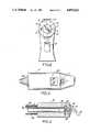
- FIG. 1is a longitudinal cross-section view of the temperature sensing device of the present invention, indicating the various components therein, and its relationship to a patient's ear.
- FIG. 2is a frontal view of the apparatus of the present invention, where the insulating airspace is shown between the housing and sensor assembly.
- FIG. 3is a top view of the apparatus of the present invention, and indicates the display and speculum location.
- FIG. 4is a detailed, longitudinal cross-section view of subassembly 10 from FIG. 1.
- FIG. 5is an assembly view of one particular arrangement of the present invention.
- FIG. 1a detailed cross-section view of the inner components of subject invention is presented.
- the apparatusis shown in relationship to a patient's ear 100. More specifically, ear 100 is shown with ear canal 2, terminating with ear drum 1.
- the ear drumis characterized by a tympanic membrane generally disposed outward and down ear canal 2. This tympanic membrane emits infrared radiation in proportion to its temperature; infrared radiation travels down the ear canal and becomes available for collection at the ear opening.
- the temperature measuring apparatus as presented in FIG. 1has housing 5 which provides an enclosure of the working elements of the device.
- Housing 5can be made of any material suitable for containing electronic components, but is preferably constructed in a lightweight rigid plastic material.
- Plasticis preferred for its relatively high strength/weight ratio, ease in manufacturing through injection molding techniques, low thermal conductivity, and for the relatively inexpensive material costs associated with most plastics. It may be that more demanding uses and environments will require other materials such as composites or fiberglass for housing 5, but for most applications, plastics such as polyethylene and polypropylene should suffice.
- spacer studs 4Integral with Housing 5, are spacer studs 4 that extend radially inwards from the housing wall. These spacer studs, preferably made of material of low thermal conductivity such as nylon, structurally support the infrared radiation sensor assembly which is designated by the numeral 10, within airspace 3 in housing 5.
- airspace 3provides an insulative layer of air that surrounds infrared radiation sensor assembly 10 and minimizes the heat transfer from heat sources external to housing 5 to the infrared radiation sensor assembly.
- airspace 3can be seen as the annular region between the housing wall and the infrared radiation sensor assembly 10.
- the broken lines in FIG. 2represent spacer studs 4 retaining the annular position of the infrared radiation sensor assembly 10.
- airspace 3will provide a sufficient insulative barrier between the housing wall and the infrared radiation sensor assembly.
- insulative meanscan be substituted for the more demanding applications. These can include freon-filled foamed polymers, vacuum gap, or similar. The extra cost associated with such insulative means must, of course, be justified by the need for a lower heat transfer rate or smaller dimensioned housing.
- the distance between the housing wall and infrared radiation assembly 10is not particularly limitative, and can range between 5 and 50 mm.
- Airspace 9acts to insulate wave guide 11 from heat sources external to speculum 25.
- a low emissivity barrier 9asuch as polished or gold plated aluminum tubing, is placed around the protruding portion of the wave guide.
- air space 9b and a plastic low thermal conductivity covering, 9c over tubing 9aprovides further thermal protection for the protruding portion of the wave guide.
- PCB 35Printed Circuit Board designated as 35 in FIG. 1 is positioned within housing 5.
- the PCBprovides the signal processing for the apparatus. More particularly, PCB 35 receives a signal from infrared radiation sensor assembly 10, via cable 8. This signal is amplified and converted via the circuitry on PCB 35 by means well known in the electronics art, i.e., the input signal is amplified sufficiently to drive the display 50, and also converted to reflect the temperature units for the system (i.e., Fahrenheit or Celsius).
- the PCBis powered by power supply 40 via cable 41.
- the power supplyis preferably a long life 9-Volt size battery, but other sources of power can be easily substituted.
- PCB 35is connected to display 50, which is external to housing 5.
- display 50is shown on the top of housing 5.
- Display 50is preferably a liquid crystal display (LCD) since the LCD requires little power. LCD's perform best in brightly lit environments; obviously if the apparatus has expected duties in low-light areas, other displays such as light emitting diode displays (LED's) can be easily substituted. For most purposes, the LCD should suffice, and is connected to PCB 35 via conductive ribbon connector 51 (In FIG. 1). Control of the apparatus is made by switch 6 as connected by cable 70 to PCB 35.
- LCDliquid crystal display
- infrared radiation sensor assembly 10partially extends outside housing 5 through opening 80, thus forming the portion of the apparatus that is directed toward the infrared radiation emissive target (e.g., ear drum).
- disposable speculum 25is used to cover the infrared radiation sensor assembly as it extends outside of housing 5. More particularly, disposable speculum 25 snugly fits onto housing 5 via frictional forces as translated through retaining nub 30. This snug fit is formed by depressing the cup shaped speculum over the housing opening.
- Speculum 25is formed of an infrared radiation transparent material such as polyethylene or polypropylene which also are quite inexpensive. Removal of speculum 25 is accomplished by depressing switch 7.
- switch 7causes the extension of push rod 39 which in turn, causes the dislocation of the speculum from retaining nub 30.
- Spring 31acts to retract push rod 39 and switch 7 into their unextended position in preparation for receipt of another disposable speculum. In addition to speculum disposal, it may be cost effective to provide speculums capable of recycle (after cleaning).
- Wave guide 11provides a uniform cylindrical tube with the open end extending outside housing 5 (as shown in FIG. 1 and discussed above), and the opposite end terminating at infrared radiation detector 18.
- the dimensions and orientation of wave guide 11are such that the field of view of infrared radiation detector 18 is shaped to an angle of about six (6) degrees, so that the infrared radiation detector "sees" the infrared radiation emanating from the tympanic membrane (1 in FIG. 1) with little or no radiation from the ear canal.
- the wave guidecan be constructed of materials of relatively low infrared radiation emissivity with aluminum being preferred.
- the infrared radiation detector 18is preferably the thermopile type, which has become recognized in other industrial devices for infrared radiation detection.
- Thermopilesare equipped with plural reference (cold) junctions which, of course, are affected by ambient temperature.
- Plural detector posts, 16,are placed in close thermal contact with the reference junctions.
- Contact temperature sensor 13, such as a thermistor or thermocouple,is placed in close proximity to detector posts 16.
- the infrared radiation detector, detector posts 16, and thermistor 13are bound together by an epoxy compound 19. Any means of binding the above components will be suitable if the components are combined in a manner that retains substantial isothermic conditions among the components, i.e., the detector, junctions, and thermistor are held at the same (ambient) temperature.
- Block 12extends contiguously over a substantial portion of wave guide 11 and the detector assembly.
- Block 12should be constructed of a good heat conductor, such as aluminum or copper with aluminum being preferred due to its lower infrared radiation emissivity.
- Block 12should be of sufficient mass as to retain substantial isothermic conditions over the other components in infrared radiation sensor assembly 10.
- Cable 14 and 17act to transmit the thermistor and infrared radiation detector signals respectively.
- Protective barrier 9aextends from block 12 concentrically around wave guide 11.
- Plastic cover 9cis contiguous to barrier 9a, with airspace 9b between 9a and wave guide 11.
- the objective of the above-described relationshipis to maintain isothermic conditions among the various components in the infrared radiation sensor assembly, even when ambient temperature changes. Since reference junctions are held at the same temperature of the components proximate thereto, these components now become infrared radiation "invisible" to infrared radiation detector 18. Furthermore, changes in ambient temperature will not affect the reading of the device, since ambient air temperature changes that result in a temperature change in the infrared radiation sensor assembly 10 are measured by thermistor 13, which thus provides a signal to compensate for the corresponding temperature shift. Finally, since infrared radiation sensor assembly 10 is thermally insulated from the environment via airspace 3 (See FIG.
- the outer housingis shaped in a manner that allows the operator's thumb to depress the sensor switch while the operator's fingers form a flush surface that is rested on the patient's cheek during the measurement process.
- This shapeis important for two reasons. First, the procedure of using the invention apparatus will closely assimilate the per se well known use of otoscopes. Second, the geometry of the apparatus permits accurate alignment of the wave guide with the ear canal, thus enhancing signal accuracy.
- the use of the temperature sensing apparatusis substantially enhanced by the above design considerations.
- the procedureis initiated by placing a fresh speculum onto the sensor device.
- the disposable speculumis shaped to fit into the ear canal opening in a fashion that directs the device toward the tympanic membrane, i.e., infrared radiation detector 18 and the tympanic membrane become opposed to each other and coupled by the combined de facto wave guide formed by the ear canal and wave guide 11.
- the user of the devicemerely positions the speculum lightly into the ear at an approximate perpendicular orientation. As discussed above, the proper orientation is easily attained, pursuant to the shape of the apparatus in conjunction with applying the procedure used with otoscopes.
- the userdepresses trigger switch 6 to obtain a temperature reading, usually in under two (2) seconds, and removes the device from the patient.
- the speculumis disposed of by depressing switch 7, dumping the speculum into a waste receptacle.
- the LCD displayretains the measured tympanic temperature which can be recorded by per se well-known means. A new speculum is placed onto the device, which is now ready for the next measurement.
- the infrared radiation detectoris exposed to infrared radiation from the tympanic membrane, and generates an electrical signal corresponding to this infrared radiation exposure.
- thermistor 13measures the real time temperature of the infrared radiation sensor assembly and generates a signal corresponding to this temperature.
- the infrared radiation signalis amplified, converted to temperature units and adjusted by the real time temperature of the infrared radiation sensor assembly vis-a-vis the thermistor signal.
- the resulting adjusted temperature signalis transmitted to display 50 providing the output from the device to the user.
Landscapes
- Physics & Mathematics (AREA)
- General Physics & Mathematics (AREA)
- Spectroscopy & Molecular Physics (AREA)
- Life Sciences & Earth Sciences (AREA)
- Health & Medical Sciences (AREA)
- Engineering & Computer Science (AREA)
- Heart & Thoracic Surgery (AREA)
- General Health & Medical Sciences (AREA)
- Pathology (AREA)
- Biomedical Technology (AREA)
- Human Computer Interaction (AREA)
- Medical Informatics (AREA)
- Molecular Biology (AREA)
- Surgery (AREA)
- Animal Behavior & Ethology (AREA)
- Biophysics (AREA)
- Public Health (AREA)
- Veterinary Medicine (AREA)
- Measuring And Recording Apparatus For Diagnosis (AREA)
- Radiation Pyrometers (AREA)
- Crystals, And After-Treatments Of Crystals (AREA)
- Pharmaceuticals Containing Other Organic And Inorganic Compounds (AREA)
- Surgical Instruments (AREA)
Abstract
Description
Claims (21)
Priority Applications (7)
| Application Number | Priority Date | Filing Date | Title |
|---|---|---|---|
| US07/244,738US4895164A (en) | 1988-09-15 | 1988-09-15 | Infrared clinical thermometer |
| DE68927000TDE68927000T3 (en) | 1988-09-15 | 1989-09-12 | INFRARED THERMOMETER CLINIC |
| EP89910765AEP0388463B2 (en) | 1988-09-15 | 1989-09-12 | Infrared clinical thermometer |
| AT89910765TATE141477T1 (en) | 1988-09-15 | 1989-09-12 | INFRARED CLINICAL THERMOMETER |
| PCT/US1989/003976WO1990002521A1 (en) | 1988-09-15 | 1989-09-12 | Infrared clinical thermometer |
| JP1510139AJPH03501820A (en) | 1988-09-15 | 1989-09-12 | infrared thermometer |
| CA000611375ACA1326967C (en) | 1988-09-15 | 1989-09-14 | Infrared clinical thermometer |
Applications Claiming Priority (1)
| Application Number | Priority Date | Filing Date | Title |
|---|---|---|---|
| US07/244,738US4895164A (en) | 1988-09-15 | 1988-09-15 | Infrared clinical thermometer |
Publications (1)
| Publication Number | Publication Date |
|---|---|
| US4895164Atrue US4895164A (en) | 1990-01-23 |
Family
ID=22923930
Family Applications (1)
| Application Number | Title | Priority Date | Filing Date |
|---|---|---|---|
| US07/244,738Expired - Fee RelatedUS4895164A (en) | 1988-09-15 | 1988-09-15 | Infrared clinical thermometer |
Country Status (7)
| Country | Link |
|---|---|
| US (1) | US4895164A (en) |
| EP (1) | EP0388463B2 (en) |
| JP (1) | JPH03501820A (en) |
| AT (1) | ATE141477T1 (en) |
| CA (1) | CA1326967C (en) |
| DE (1) | DE68927000T3 (en) |
| WO (1) | WO1990002521A1 (en) |
Cited By (82)
| Publication number | Priority date | Publication date | Assignee | Title |
|---|---|---|---|---|
| US4993419A (en)* | 1988-12-06 | 1991-02-19 | Exergen Corporation | Radiation detector suitable for tympanic temperature measurement |
| US5012813A (en)* | 1988-12-06 | 1991-05-07 | Exergen Corporation | Radiation detector having improved accuracy |
| US5017018A (en)* | 1987-12-25 | 1991-05-21 | Nippon Steel Corporation | Clinical thermometer |
| USD317414S (en) | 1989-05-08 | 1991-06-11 | Ivac Corporation | Handheld infrared thermometer |
| USD321487S (en) | 1989-04-24 | 1991-11-12 | Diatek Incorporated | Infrared thermometer |
| US5066142A (en)* | 1990-03-08 | 1991-11-19 | Ivac Corporation | Protective apparatus for a biomedical probe |
| US5081359A (en)* | 1990-05-23 | 1992-01-14 | Exergen Corporation | Differential thermal sensor |
| EP0445783A3 (en)* | 1990-03-08 | 1992-04-29 | Ivac Corporation | Thermally isolated probe |
| WO1992010133A1 (en)* | 1990-12-12 | 1992-06-25 | Intelligent Medical Systems, Inc. | Infrared thermometer utilizing calibration mapping |
| USD329396S (en) | 1990-09-13 | 1992-09-15 | Thermoscan Inc. | Radiation thermometer |
| USD329395S (en) | 1990-09-13 | 1992-09-15 | Thermoscan Inc. | Radiation thermometer |
| US5159936A (en)* | 1990-08-17 | 1992-11-03 | Mark Yelderman | Noncontact infrared tympanic thermometer |
| US5167235A (en)* | 1991-03-04 | 1992-12-01 | Pat O. Daily Revocable Trust | Fiber optic ear thermometer |
| US5188459A (en)* | 1990-11-29 | 1993-02-23 | Horiba, Ltd. | Protective shield accessory for measurement instrument |
| US5199436A (en)* | 1988-12-06 | 1993-04-06 | Exergen Corporation | Radiation detector having improved accuracy |
| JPH05115443A (en)* | 1990-03-12 | 1993-05-14 | Ivac Corp | System for temperature determination and calibration in biomedical thermometers |
| USD337534S (en) | 1991-03-28 | 1993-07-20 | Swift Arlette B | Tympanic thermometer |
| USD337954S (en) | 1991-01-24 | 1993-08-03 | Shigeru Makita | Thermometer |
| US5271407A (en)* | 1988-12-06 | 1993-12-21 | Exergen Corporation | Radiation detector suitable for tympanic temperature measurement |
| USRE34599E (en)* | 1988-11-01 | 1994-05-03 | Diatek Incorporated | Disposable probe cover assembly for medical thermometer |
| US5319202A (en)* | 1990-08-01 | 1994-06-07 | Exergen Corporation | Radiation detector with remote temperature reference |
| US5325863A (en)* | 1988-12-06 | 1994-07-05 | Exergen Corporation | Radiation detector with high thermal stability |
| US5381796A (en)* | 1992-05-22 | 1995-01-17 | Exergen Corporation | Ear thermometer radiation detector |
| US5411032A (en)* | 1993-06-18 | 1995-05-02 | Infra-Temp Inc. | Electronic thermometer probe cover |
| US5445158A (en)* | 1988-12-06 | 1995-08-29 | Exergen Corporation | Radiation detector probe |
| US5458121A (en)* | 1992-09-17 | 1995-10-17 | Terumo Kabushiki Kaisha | Clinical thermometer |
| US5469855A (en)* | 1991-03-08 | 1995-11-28 | Exergen Corporation | Continuous temperature monitor |
| US5487607A (en)* | 1992-04-08 | 1996-01-30 | Omron Corporation | Radiation clinical thermometer |
| US5516010A (en)* | 1984-10-23 | 1996-05-14 | Sherwood Medical Company | Sanitary speculum for tympanic thermometer probe |
| US5522662A (en)* | 1993-04-01 | 1996-06-04 | Terumo Kabushiki Kaisha | Clinical thermometer |
| US5528041A (en)* | 1990-08-01 | 1996-06-18 | Exergen Corporation | Radiation detector with remote temperature reference |
| WO1997001083A1 (en)* | 1995-06-23 | 1997-01-09 | Thermoscan, Inc. | Durable tympanic probe and thermometer |
| US5614716A (en)* | 1996-04-26 | 1997-03-25 | Infratemp, Inc. | Alternating current method and apparatus for ambient temperature compensation for modulated energy sensors |
| US5626139A (en)* | 1994-09-23 | 1997-05-06 | Artech Industries, Inc. | Tympanic thermometer |
| US5626147A (en)* | 1993-11-23 | 1997-05-06 | Thermoscan, Inc. | Tympanic thermometer |
| US5629676A (en)* | 1994-07-25 | 1997-05-13 | Rokonet Electronics, Limited | Alarm system |
| US5645350A (en)* | 1996-04-12 | 1997-07-08 | Jang; Chen-Chang | Hygienic protecting device for an electronic thermometer |
| US5653238A (en)* | 1988-12-06 | 1997-08-05 | Exergen Corporation | Radiation detector probe |
| US5725308A (en)* | 1994-12-23 | 1998-03-10 | Rtd Technology, Inc. | Quick registering thermometer |
| US5833367A (en) | 1996-11-12 | 1998-11-10 | Trutek, Inc. | Tympanic thermometer probe cover |
| US5872362A (en)* | 1990-08-01 | 1999-02-16 | Exergen Corporation | Radiation detector with remote temperature reference |
| DE29819056U1 (en) | 1998-10-26 | 1999-02-25 | Chen, Chao-Wang, Taipeh/T'ai-pei | Infrared thermometer |
| WO1999034729A1 (en) | 1998-01-12 | 1999-07-15 | Mdi Instruments, Inc. | Ear examining device with temperature sensor |
| DE19815927A1 (en)* | 1998-04-09 | 1999-10-14 | Braun Gmbh | Infrared radiation thermometer with otoscope function |
| US5967992A (en) | 1998-06-03 | 1999-10-19 | Trutex, Inc. | Radiometric temperature measurement based on empirical measurements and linear functions |
| US5991652A (en)* | 1997-03-17 | 1999-11-23 | Thermoscan Inc. | Protective two position shell for an infrared thermometer |
| US6001066A (en) | 1997-06-03 | 1999-12-14 | Trutek, Inc. | Tympanic thermometer with modular sensing probe |
| US6030117A (en) | 1996-11-12 | 2000-02-29 | Trutek, Inc. | Tympanic thermometer probe cover |
| US6058356A (en)* | 1998-04-30 | 2000-05-02 | Cooper Instrument Corporation | Hand-held electronic instrument |
| WO2000024312A1 (en) | 1998-10-23 | 2000-05-04 | Becton, Dickinson And Company | Sensing ear temperature, acoustic reflectance and chemical components in the ear |
| US6109782A (en)* | 1995-12-28 | 2000-08-29 | Omron Corporation | Infrared thermometer |
| US6123454A (en) | 1999-06-11 | 2000-09-26 | Trutek, Inc. | Tympanic thermometer disposable probe cover with further stretching prevention structure |
| US6219573B1 (en) | 1989-04-14 | 2001-04-17 | Exergen Corporation | Radiation detector probe |
| US6241384B1 (en)* | 1996-10-25 | 2001-06-05 | Exergen Corporation | Axillary infrared thermometer and method of use |
| US6357909B1 (en)* | 1997-09-10 | 2002-03-19 | Citizen Watch Co., Ltd. | Radiation pyrometer |
| US6435711B1 (en) | 1998-09-15 | 2002-08-20 | Jonathan Gerlitz | Infrared ear thermometer |
| US6513970B1 (en) | 1998-10-20 | 2003-02-04 | Omron Corporation | Infrared thermometer |
| US6637931B2 (en) | 2001-07-19 | 2003-10-28 | Oriental System Technology Inc. | Probe for use in an infrared thermometer |
| US6695474B2 (en) | 1996-02-06 | 2004-02-24 | Braun Aktiengesellschaft | Protective cap for infrared radiation thermometer |
| US20040086022A1 (en)* | 2001-02-19 | 2004-05-06 | Bernhard Kraus | Radiation thermometer comprising a heated measuring tip |
| USD493733S1 (en) | 2003-12-02 | 2004-08-03 | Li-Chuan Chen | Infrared thermometer |
| US20040152991A1 (en)* | 1998-09-11 | 2004-08-05 | Exergen Corporation | Temporal artery temperature detector |
| US20040240516A1 (en)* | 2002-12-12 | 2004-12-02 | James Harr | Thermal tympanic thermometer tip |
| US20050083991A1 (en)* | 2003-10-17 | 2005-04-21 | Anthony Wong | Probe cover storage system for ear thermometer |
| US20050085733A1 (en)* | 2003-10-17 | 2005-04-21 | Anthony Wong | Ear thermometer illumination system |
| US20050145964A1 (en)* | 2003-10-06 | 2005-07-07 | Akiko Suzuki | Optical sensor and method of manufacturing the same |
| US20060222048A1 (en)* | 1997-06-24 | 2006-10-05 | Francesco Pompei | Ambient and perfusion normalized temperature detector |
| US20060239332A1 (en)* | 2002-12-12 | 2006-10-26 | Sherwood Services Ag | Thermal tympanic thermometer |
| US20070047620A1 (en)* | 2005-08-29 | 2007-03-01 | Lumpkin Wayne R | Infrared thermometer with an axially actuated temperature sensor |
| US20070127545A1 (en)* | 2005-12-01 | 2007-06-07 | Oriental System Technology Inc. | Probe assembly of infrared thermometer |
| US20080267254A1 (en)* | 2007-04-27 | 2008-10-30 | Actherm Inc. | Infrared thermometer |
| US20090172591A1 (en)* | 2007-12-28 | 2009-07-02 | Pomper Kenneth A | Portable IR Thermometer Having Graphical User Display and Interface |
| US20090185598A1 (en)* | 2006-04-21 | 2009-07-23 | Tyco Healthcare Group Lp | Probe cover having a blackbody |
| US20110194585A1 (en)* | 2010-02-09 | 2011-08-11 | Abhishek Shrivastava | Multiple object non-contact thermometer |
| US20110228810A1 (en)* | 2010-02-09 | 2011-09-22 | O'hara Gary | Multiple object talking non-contact thermometer |
| EP2437039A2 (en) | 2010-09-30 | 2012-04-04 | Medisim Ltd. | Ergonomic hand held thermometer |
| CN105286807A (en)* | 2015-09-17 | 2016-02-03 | 深圳市科迈通讯技术有限公司 | Temperature measurement method and system based on internet |
| US9307912B2 (en) | 2012-08-08 | 2016-04-12 | Welch Allyn, Inc. | Temperature measurement system |
| US20170143198A1 (en)* | 2015-11-25 | 2017-05-25 | Htc Corporation | Hybrid detection apparatus |
| US20170211993A1 (en)* | 2016-01-21 | 2017-07-27 | Honeywell International Inc. | Body core temperature measurement |
| US20210128843A1 (en)* | 2017-07-21 | 2021-05-06 | Min Bo SHIM | Tip for intra-tympanic injection |
| US20230068534A1 (en)* | 2021-08-31 | 2023-03-02 | Starkey Laboratories, Inc. | Ear-wearable electronic device including in-canal temperature sensor |
Families Citing this family (8)
| Publication number | Priority date | Publication date | Assignee | Title |
|---|---|---|---|---|
| US5063938A (en)* | 1990-11-01 | 1991-11-12 | Beck Donald C | Respiration-signalling device |
| DE29501672U1 (en)* | 1995-02-02 | 1995-08-03 | Maier, Andreas, Dipl.-Ing. (FH), 85416 Langenbach | Hand-held measuring device, for contactless, simultaneous measurement of temperature and pulse in the human ear canal, for clinical nursing, using infrared measurement technology |
| AU7234698A (en)* | 1998-05-08 | 1999-11-29 | Kazuhito Sakano | Radiation thermometer |
| WO2000004353A1 (en)* | 1998-07-14 | 2000-01-27 | Kazuhito Sakano | Radiation thermometer |
| WO2000022390A1 (en)* | 1998-10-15 | 2000-04-20 | Kazuhito Sakano | Infrared sensor and radiation thermometer |
| JP3770265B2 (en)* | 1998-10-20 | 2006-04-26 | オムロンヘルスケア株式会社 | Infrared thermometer |
| JP6308353B2 (en)* | 2013-11-20 | 2018-04-11 | セイコーエプソン株式会社 | Liquid ejection device |
| JP5996139B1 (en)* | 2016-03-31 | 2016-09-21 | 興和株式会社 | Infrared thermometer |
Citations (8)
| Publication number | Priority date | Publication date | Assignee | Title |
|---|---|---|---|---|
| US3492058A (en)* | 1967-02-03 | 1970-01-27 | Gen Dynamics Corp | Detector lens assembly |
| US3491596A (en)* | 1967-10-02 | 1970-01-27 | Vito Charles P De | Temperature sensing device |
| US3581570A (en)* | 1967-09-05 | 1971-06-01 | Garrett Corp | Thermal radiation sensor |
| US3718437A (en)* | 1970-12-28 | 1973-02-27 | P Paloniemi | Isothermal calorimeter |
| DE2836462A1 (en)* | 1978-08-21 | 1980-03-06 | Woerl Alarm August Woerl Inhab | Room surveillance sensor system - uses optical lens assembly to focus IR emissions onto detector stage |
| US4602642A (en)* | 1984-10-23 | 1986-07-29 | Intelligent Medical Systems, Inc. | Method and apparatus for measuring internal body temperature utilizing infrared emissions |
| US4634294A (en)* | 1979-09-12 | 1987-01-06 | Raytek, Inc. | Hand-held digital temperature measuring instrument |
| US4636091A (en)* | 1985-06-27 | 1987-01-13 | Exergen Corporation | Radiation detector having temperature readout |
Family Cites Families (3)
| Publication number | Priority date | Publication date | Assignee | Title |
|---|---|---|---|---|
| US4566808A (en)* | 1983-02-16 | 1986-01-28 | Exergen Corporation | Scanning radiation detector |
| JPS6130731A (en)* | 1984-07-24 | 1986-02-13 | Chino Works Ltd | radiant energy detector |
| US4797840A (en)* | 1985-04-17 | 1989-01-10 | Thermoscan Inc. | Infrared electronic thermometer and method for measuring temperature |
- 1988
- 1988-09-15USUS07/244,738patent/US4895164A/ennot_activeExpired - Fee Related
- 1989
- 1989-09-12WOPCT/US1989/003976patent/WO1990002521A1/enactiveIP Right Grant
- 1989-09-12DEDE68927000Tpatent/DE68927000T3/ennot_activeExpired - Fee Related
- 1989-09-12JPJP1510139Apatent/JPH03501820A/enactiveGranted
- 1989-09-12EPEP89910765Apatent/EP0388463B2/ennot_activeExpired - Lifetime
- 1989-09-12ATAT89910765Tpatent/ATE141477T1/ennot_activeIP Right Cessation
- 1989-09-14CACA000611375Apatent/CA1326967C/ennot_activeExpired - Fee Related
Patent Citations (8)
| Publication number | Priority date | Publication date | Assignee | Title |
|---|---|---|---|---|
| US3492058A (en)* | 1967-02-03 | 1970-01-27 | Gen Dynamics Corp | Detector lens assembly |
| US3581570A (en)* | 1967-09-05 | 1971-06-01 | Garrett Corp | Thermal radiation sensor |
| US3491596A (en)* | 1967-10-02 | 1970-01-27 | Vito Charles P De | Temperature sensing device |
| US3718437A (en)* | 1970-12-28 | 1973-02-27 | P Paloniemi | Isothermal calorimeter |
| DE2836462A1 (en)* | 1978-08-21 | 1980-03-06 | Woerl Alarm August Woerl Inhab | Room surveillance sensor system - uses optical lens assembly to focus IR emissions onto detector stage |
| US4634294A (en)* | 1979-09-12 | 1987-01-06 | Raytek, Inc. | Hand-held digital temperature measuring instrument |
| US4602642A (en)* | 1984-10-23 | 1986-07-29 | Intelligent Medical Systems, Inc. | Method and apparatus for measuring internal body temperature utilizing infrared emissions |
| US4636091A (en)* | 1985-06-27 | 1987-01-13 | Exergen Corporation | Radiation detector having temperature readout |
Non-Patent Citations (2)
| Title |
|---|
| Tympanic Clinical Temperature, M. Benzinger et al., Jun. 21 24, 1971, presented at Fifth Symposium on Temperature, Washington, D.C.* |
| Tympanic Clinical Temperature, M. Benzinger et al., Jun. 21-24, 1971, presented at Fifth Symposium on Temperature, Washington, D.C. |
Cited By (130)
| Publication number | Priority date | Publication date | Assignee | Title |
|---|---|---|---|---|
| US5516010A (en)* | 1984-10-23 | 1996-05-14 | Sherwood Medical Company | Sanitary speculum for tympanic thermometer probe |
| US5980451A (en) | 1984-10-23 | 1999-11-09 | Sherwood Services Ag | Disposable speculum with membrane bonding ring |
| US5707343A (en)* | 1984-10-23 | 1998-01-13 | O'hara; Gary J. | Disposable sanitary speculum for timpanic thermometer probe |
| US5017018A (en)* | 1987-12-25 | 1991-05-21 | Nippon Steel Corporation | Clinical thermometer |
| USRE34599E (en)* | 1988-11-01 | 1994-05-03 | Diatek Incorporated | Disposable probe cover assembly for medical thermometer |
| US20040122338A1 (en)* | 1988-12-06 | 2004-06-24 | Exergen Corporation | Radiation detector probe |
| US4993419A (en)* | 1988-12-06 | 1991-02-19 | Exergen Corporation | Radiation detector suitable for tympanic temperature measurement |
| US5012813A (en)* | 1988-12-06 | 1991-05-07 | Exergen Corporation | Radiation detector having improved accuracy |
| US5653238A (en)* | 1988-12-06 | 1997-08-05 | Exergen Corporation | Radiation detector probe |
| US20060062274A1 (en)* | 1988-12-06 | 2006-03-23 | Exergen Corporation | Radiation detector probe |
| US5271407A (en)* | 1988-12-06 | 1993-12-21 | Exergen Corporation | Radiation detector suitable for tympanic temperature measurement |
| US6047205A (en)* | 1988-12-06 | 2000-04-04 | Exergen Corporation | Radiation detector probe |
| US5445158A (en)* | 1988-12-06 | 1995-08-29 | Exergen Corporation | Radiation detector probe |
| US5199436A (en)* | 1988-12-06 | 1993-04-06 | Exergen Corporation | Radiation detector having improved accuracy |
| US5325863A (en)* | 1988-12-06 | 1994-07-05 | Exergen Corporation | Radiation detector with high thermal stability |
| US6219573B1 (en) | 1989-04-14 | 2001-04-17 | Exergen Corporation | Radiation detector probe |
| USD321487S (en) | 1989-04-24 | 1991-11-12 | Diatek Incorporated | Infrared thermometer |
| USD317414S (en) | 1989-05-08 | 1991-06-11 | Ivac Corporation | Handheld infrared thermometer |
| EP0674162A3 (en)* | 1990-03-08 | 1995-10-18 | Ivac Corp | |
| US5066142A (en)* | 1990-03-08 | 1991-11-19 | Ivac Corporation | Protective apparatus for a biomedical probe |
| EP0445784A3 (en)* | 1990-03-08 | 1992-04-29 | Ivac Corporation | Protective apparatus for a biomedical probe |
| US6332090B1 (en)* | 1990-03-08 | 2001-12-18 | Alaris Medical Systems, Inc. | Thermally isolated probe for biomedical apparatus and method of communicating energy there through |
| JP2603003B2 (en) | 1990-03-08 | 1997-04-23 | アイバック、コーポレーション | Insulated probe |
| EP0445783A3 (en)* | 1990-03-08 | 1992-04-29 | Ivac Corporation | Thermally isolated probe |
| JPH05261069A (en)* | 1990-03-08 | 1993-10-12 | Ivac Corp | Adiabatic probe |
| JPH05115443A (en)* | 1990-03-12 | 1993-05-14 | Ivac Corp | System for temperature determination and calibration in biomedical thermometers |
| US5081359A (en)* | 1990-05-23 | 1992-01-14 | Exergen Corporation | Differential thermal sensor |
| US6617581B2 (en) | 1990-08-01 | 2003-09-09 | Exergen Corporation | Radiation detector with remote temperature reference |
| US5872362A (en)* | 1990-08-01 | 1999-02-16 | Exergen Corporation | Radiation detector with remote temperature reference |
| US6423970B1 (en) | 1990-08-01 | 2002-07-23 | Exergen Corporation | Radiation detector with remote temperature reference |
| US5319202A (en)* | 1990-08-01 | 1994-06-07 | Exergen Corporation | Radiation detector with remote temperature reference |
| US5528041A (en)* | 1990-08-01 | 1996-06-18 | Exergen Corporation | Radiation detector with remote temperature reference |
| US5159936A (en)* | 1990-08-17 | 1992-11-03 | Mark Yelderman | Noncontact infrared tympanic thermometer |
| USD329396S (en) | 1990-09-13 | 1992-09-15 | Thermoscan Inc. | Radiation thermometer |
| USD329395S (en) | 1990-09-13 | 1992-09-15 | Thermoscan Inc. | Radiation thermometer |
| US5188459A (en)* | 1990-11-29 | 1993-02-23 | Horiba, Ltd. | Protective shield accessory for measurement instrument |
| US5293877A (en)* | 1990-12-12 | 1994-03-15 | Sherwood Ims, Inc. | Body temperature thermometer and method fo measuring human body temperature utilizing calibration mapping |
| WO1992010133A1 (en)* | 1990-12-12 | 1992-06-25 | Intelligent Medical Systems, Inc. | Infrared thermometer utilizing calibration mapping |
| USD337954S (en) | 1991-01-24 | 1993-08-03 | Shigeru Makita | Thermometer |
| US5167235A (en)* | 1991-03-04 | 1992-12-01 | Pat O. Daily Revocable Trust | Fiber optic ear thermometer |
| US5469855A (en)* | 1991-03-08 | 1995-11-28 | Exergen Corporation | Continuous temperature monitor |
| US5653239A (en)* | 1991-03-08 | 1997-08-05 | Exergen Corporation | Continuous temperature monitor |
| USD337534S (en) | 1991-03-28 | 1993-07-20 | Swift Arlette B | Tympanic thermometer |
| US5487607A (en)* | 1992-04-08 | 1996-01-30 | Omron Corporation | Radiation clinical thermometer |
| US5628323A (en)* | 1992-05-22 | 1997-05-13 | Exergen Corporation | Ear thermometer radiation detector |
| US5873833A (en)* | 1992-05-22 | 1999-02-23 | Exergen Corporation | Ear thermometer radiation detector |
| US5381796A (en)* | 1992-05-22 | 1995-01-17 | Exergen Corporation | Ear thermometer radiation detector |
| US5458121A (en)* | 1992-09-17 | 1995-10-17 | Terumo Kabushiki Kaisha | Clinical thermometer |
| US5522662A (en)* | 1993-04-01 | 1996-06-04 | Terumo Kabushiki Kaisha | Clinical thermometer |
| US5411032A (en)* | 1993-06-18 | 1995-05-02 | Infra-Temp Inc. | Electronic thermometer probe cover |
| US5626147A (en)* | 1993-11-23 | 1997-05-06 | Thermoscan, Inc. | Tympanic thermometer |
| US5629676A (en)* | 1994-07-25 | 1997-05-13 | Rokonet Electronics, Limited | Alarm system |
| US5626139A (en)* | 1994-09-23 | 1997-05-06 | Artech Industries, Inc. | Tympanic thermometer |
| US5725308A (en)* | 1994-12-23 | 1998-03-10 | Rtd Technology, Inc. | Quick registering thermometer |
| US6059452A (en)* | 1994-12-23 | 2000-05-09 | Rtd Technology, Inc. | Quick registering thermometer |
| US5871279A (en)* | 1995-06-23 | 1999-02-16 | Thermoscan, Inc. | Durable tympanic probe and thermometer |
| WO1997001083A1 (en)* | 1995-06-23 | 1997-01-09 | Thermoscan, Inc. | Durable tympanic probe and thermometer |
| US6109782A (en)* | 1995-12-28 | 2000-08-29 | Omron Corporation | Infrared thermometer |
| US6695474B2 (en) | 1996-02-06 | 2004-02-24 | Braun Aktiengesellschaft | Protective cap for infrared radiation thermometer |
| US5645350A (en)* | 1996-04-12 | 1997-07-08 | Jang; Chen-Chang | Hygienic protecting device for an electronic thermometer |
| US5614716A (en)* | 1996-04-26 | 1997-03-25 | Infratemp, Inc. | Alternating current method and apparatus for ambient temperature compensation for modulated energy sensors |
| US6241384B1 (en)* | 1996-10-25 | 2001-06-05 | Exergen Corporation | Axillary infrared thermometer and method of use |
| US6042266A (en) | 1996-11-12 | 2000-03-28 | Trutek, Inc. | Tympanic thermometer probe cover |
| US6030117A (en) | 1996-11-12 | 2000-02-29 | Trutek, Inc. | Tympanic thermometer probe cover |
| US5833367A (en) | 1996-11-12 | 1998-11-10 | Trutek, Inc. | Tympanic thermometer probe cover |
| US5991652A (en)* | 1997-03-17 | 1999-11-23 | Thermoscan Inc. | Protective two position shell for an infrared thermometer |
| US6186959B1 (en) | 1997-06-03 | 2001-02-13 | Trutek, Inc. | Tympanic thermometer with modular sensing probe |
| US6001066A (en) | 1997-06-03 | 1999-12-14 | Trutek, Inc. | Tympanic thermometer with modular sensing probe |
| US7314309B2 (en)* | 1997-06-24 | 2008-01-01 | Exergen Corporation | Ambient and perfusion normalized temperature detector |
| US20060222048A1 (en)* | 1997-06-24 | 2006-10-05 | Francesco Pompei | Ambient and perfusion normalized temperature detector |
| US6357909B1 (en)* | 1997-09-10 | 2002-03-19 | Citizen Watch Co., Ltd. | Radiation pyrometer |
| WO1999034729A1 (en) | 1998-01-12 | 1999-07-15 | Mdi Instruments, Inc. | Ear examining device with temperature sensor |
| DE19815927A1 (en)* | 1998-04-09 | 1999-10-14 | Braun Gmbh | Infrared radiation thermometer with otoscope function |
| US6058356A (en)* | 1998-04-30 | 2000-05-02 | Cooper Instrument Corporation | Hand-held electronic instrument |
| US5967992A (en) | 1998-06-03 | 1999-10-19 | Trutex, Inc. | Radiometric temperature measurement based on empirical measurements and linear functions |
| US7346386B2 (en) | 1998-09-11 | 2008-03-18 | Exergen Corporation | Temporal artery temperature detector |
| US20110092822A1 (en)* | 1998-09-11 | 2011-04-21 | Francesco Pompei | Temporal Artery Temperature Detector |
| US20040152991A1 (en)* | 1998-09-11 | 2004-08-05 | Exergen Corporation | Temporal artery temperature detector |
| US7787938B2 (en) | 1998-09-11 | 2010-08-31 | Exergen Corporation | Temporal artery temperature detector |
| US20080200830A1 (en)* | 1998-09-11 | 2008-08-21 | Exergen Corporation | Temporal artery temperature detector |
| US9194749B2 (en) | 1998-09-11 | 2015-11-24 | Exergen Corporation | Temporal artery temperature detector |
| US6811306B2 (en) | 1998-09-15 | 2004-11-02 | Jonathan Gerlitz | Infrared ear thermometer |
| US20030016728A1 (en)* | 1998-09-15 | 2003-01-23 | Jonathan Gerlitz | Infrared thermometer |
| US6435711B1 (en) | 1998-09-15 | 2002-08-20 | Jonathan Gerlitz | Infrared ear thermometer |
| US6991368B2 (en) | 1998-09-15 | 2006-01-31 | Jonathan Gerlitz | Infrared thermometer |
| US6513970B1 (en) | 1998-10-20 | 2003-02-04 | Omron Corporation | Infrared thermometer |
| WO2000024312A1 (en) | 1998-10-23 | 2000-05-04 | Becton, Dickinson And Company | Sensing ear temperature, acoustic reflectance and chemical components in the ear |
| DE29819056U1 (en) | 1998-10-26 | 1999-02-25 | Chen, Chao-Wang, Taipeh/T'ai-pei | Infrared thermometer |
| US6123454A (en) | 1999-06-11 | 2000-09-26 | Trutek, Inc. | Tympanic thermometer disposable probe cover with further stretching prevention structure |
| US20040086022A1 (en)* | 2001-02-19 | 2004-05-06 | Bernhard Kraus | Radiation thermometer comprising a heated measuring tip |
| US7014358B2 (en)* | 2001-02-19 | 2006-03-21 | Braun Gmbh | Radiation thermometer comprising a heated measuring tip |
| US6637931B2 (en) | 2001-07-19 | 2003-10-28 | Oriental System Technology Inc. | Probe for use in an infrared thermometer |
| DE10147358B4 (en)* | 2001-07-19 | 2006-03-16 | Oriental System Technology Inc. | Probe for use in an infrared thermometer |
| US20060239332A1 (en)* | 2002-12-12 | 2006-10-26 | Sherwood Services Ag | Thermal tympanic thermometer |
| US20040240516A1 (en)* | 2002-12-12 | 2004-12-02 | James Harr | Thermal tympanic thermometer tip |
| US7841767B2 (en) | 2002-12-12 | 2010-11-30 | Covidien Ag | Thermal tympanic thermometer |
| US7434991B2 (en) | 2002-12-12 | 2008-10-14 | Covidien Ag | Thermal tympanic thermometer |
| US7108419B2 (en) | 2002-12-12 | 2006-09-19 | Sherwood Services Ag | Thermal tympanic thermometer tip |
| US20080298429A1 (en)* | 2002-12-12 | 2008-12-04 | Sherwood Services Ag | Thermal tympanic thermometer |
| US7187050B2 (en) | 2003-10-06 | 2007-03-06 | Japan Aviation Electronics Industry Limited | Optical sensor and method of manufacturing the same |
| US7572648B2 (en) | 2003-10-06 | 2009-08-11 | Japan Aviation Electronics Industry Limited | Method of manufacturing optical sensor |
| US20060097334A1 (en)* | 2003-10-06 | 2006-05-11 | Japan Aviation Electronics Industry Limited | Method of manufacturing optical sensor |
| US20050145964A1 (en)* | 2003-10-06 | 2005-07-07 | Akiko Suzuki | Optical sensor and method of manufacturing the same |
| US20050083991A1 (en)* | 2003-10-17 | 2005-04-21 | Anthony Wong | Probe cover storage system for ear thermometer |
| US20050085733A1 (en)* | 2003-10-17 | 2005-04-21 | Anthony Wong | Ear thermometer illumination system |
| USD493733S1 (en) | 2003-12-02 | 2004-08-03 | Li-Chuan Chen | Infrared thermometer |
| US7507025B2 (en) | 2005-08-29 | 2009-03-24 | Wayne R Lumpkin | Infrared thermometer with an axially actuated temperature sensor |
| US20070047620A1 (en)* | 2005-08-29 | 2007-03-01 | Lumpkin Wayne R | Infrared thermometer with an axially actuated temperature sensor |
| US7275867B2 (en) | 2005-12-01 | 2007-10-02 | Oriental System Technology Inc. | Probe assembly of infrared thermometer |
| US20070127545A1 (en)* | 2005-12-01 | 2007-06-07 | Oriental System Technology Inc. | Probe assembly of infrared thermometer |
| US20090185598A1 (en)* | 2006-04-21 | 2009-07-23 | Tyco Healthcare Group Lp | Probe cover having a blackbody |
| US8123401B2 (en)* | 2006-04-21 | 2012-02-28 | Covidien Ag | Probe cover having a blackbody |
| US20080267254A1 (en)* | 2007-04-27 | 2008-10-30 | Actherm Inc. | Infrared thermometer |
| US7665892B2 (en) | 2007-04-27 | 2010-02-23 | Actherm Inc. | Infrared thermometer |
| US8549428B2 (en)* | 2007-12-28 | 2013-10-01 | Fluke Corporation | Portable IR thermometer having graphical user display and interface |
| US20090172591A1 (en)* | 2007-12-28 | 2009-07-02 | Pomper Kenneth A | Portable IR Thermometer Having Graphical User Display and Interface |
| US20110194585A1 (en)* | 2010-02-09 | 2011-08-11 | Abhishek Shrivastava | Multiple object non-contact thermometer |
| US20110228810A1 (en)* | 2010-02-09 | 2011-09-22 | O'hara Gary | Multiple object talking non-contact thermometer |
| EP2437039A2 (en) | 2010-09-30 | 2012-04-04 | Medisim Ltd. | Ergonomic hand held thermometer |
| US9474450B2 (en) | 2012-08-08 | 2016-10-25 | Welch Allyn, Inc. | Temperature measurement system |
| US9307912B2 (en) | 2012-08-08 | 2016-04-12 | Welch Allyn, Inc. | Temperature measurement system |
| US9901258B2 (en) | 2012-08-08 | 2018-02-27 | Welch Allyn, Inc. | Temperature measurement system |
| CN105286807A (en)* | 2015-09-17 | 2016-02-03 | 深圳市科迈通讯技术有限公司 | Temperature measurement method and system based on internet |
| US20170143198A1 (en)* | 2015-11-25 | 2017-05-25 | Htc Corporation | Hybrid detection apparatus |
| US10390692B2 (en)* | 2015-11-25 | 2019-08-27 | Htc Corporation | Hybrid detection apparatus |
| US20170211993A1 (en)* | 2016-01-21 | 2017-07-27 | Honeywell International Inc. | Body core temperature measurement |
| US10309835B2 (en)* | 2016-01-21 | 2019-06-04 | Honeywell International Inc. | Body core temperature measurement |
| US20210128843A1 (en)* | 2017-07-21 | 2021-05-06 | Min Bo SHIM | Tip for intra-tympanic injection |
| US11730894B2 (en)* | 2017-07-21 | 2023-08-22 | Min Bo SHIM | Tip for intra-tympanic injection |
| US20230068534A1 (en)* | 2021-08-31 | 2023-03-02 | Starkey Laboratories, Inc. | Ear-wearable electronic device including in-canal temperature sensor |
Also Published As
| Publication number | Publication date |
|---|---|
| EP0388463A1 (en) | 1990-09-26 |
| EP0388463B2 (en) | 2004-06-16 |
| JPH0528617B2 (en) | 1993-04-26 |
| DE68927000T2 (en) | 1997-01-23 |
| ATE141477T1 (en) | 1996-09-15 |
| DE68927000T3 (en) | 2005-01-05 |
| WO1990002521A1 (en) | 1990-03-22 |
| JPH03501820A (en) | 1991-04-25 |
| DE68927000D1 (en) | 1996-09-26 |
| CA1326967C (en) | 1994-02-15 |
| EP0388463B1 (en) | 1996-08-21 |
| EP0388463A4 (en) | 1991-09-25 |
Similar Documents
| Publication | Publication Date | Title |
|---|---|---|
| US4895164A (en) | Infrared clinical thermometer | |
| US4602642A (en) | Method and apparatus for measuring internal body temperature utilizing infrared emissions | |
| US4790324A (en) | Method and apparatus for measuring internal body temperature utilizing infrared emissions | |
| EP0562039B1 (en) | Infrared thermometer utilizing calibration mapping | |
| US8123401B2 (en) | Probe cover having a blackbody | |
| US5167235A (en) | Fiber optic ear thermometer | |
| CA2891503C (en) | Non-contact medical thermometer with distance sensing and compensation | |
| EP1538969B1 (en) | Combined oxygen saturation and temperature measuring apparatus | |
| US20120215113A1 (en) | Surface temperature profile | |
| WO1998019143A1 (en) | Axillary infrared thermometer and method of use | |
| Betta et al. | An assessment of infrared tympanic thermometers for body temperature measurement | |
| WO2000004353A1 (en) | Radiation thermometer | |
| HK1108025A (en) | Infrared thermometer and probe cover thereof | |
| HK1001268B (en) | Infrared thermometer utilizing calibration mapping | |
| HK1001268A (en) | Infrared thermometer utilizing calibration mapping | |
| HK1108294B (en) | A probe cover for an infrared electronic thermometer |
Legal Events
| Date | Code | Title | Description |
|---|---|---|---|
| AS | Assignment | Owner name:TEMP-STIK CORP., CALIFORNIA Free format text:ASSIGNMENT OF ASSIGNORS INTEREST.;ASSIGNOR:WOOD, DON E.;REEL/FRAME:005010/0071 Effective date:19880907 Owner name:TELATEMP CORP., CALIFORNIA Free format text:ASSIGNMENT OF ASSIGNORS INTEREST.;ASSIGNOR:WOOD, DON E.;REEL/FRAME:005010/0071 Effective date:19880907 | |
| FPAY | Fee payment | Year of fee payment:4 | |
| AS | Assignment | Owner name:INFRA-TEMP, INC., CALIFORNIA Free format text:QUITCLAIM;ASSIGNOR:WARREN DESPER AND WARREN DESPER & ASSOCIATES;REEL/FRAME:006756/0555 Effective date:19930823 Owner name:INFRA-TEMP, INC., CALIFORNIA Free format text:PATENT LICENSE AGREEMENT;ASSIGNORS:TELATEMP CORPORATION;TEMP-STIK CORPORATION;REEL/FRAME:006756/0545 Effective date:19930820 Owner name:INFRA-TEMP, INC., CALIFORNIA Free format text:PARTIES HEREBY QUITCLAIM RELEASE AND REMISE IN FOR OR OF SAID ASSIGNEE;ASSIGNOR:RALSTON, ALLEN;REEL/FRAME:006748/0554 Effective date:19930823 Owner name:ECONOMATION, INC., CALIFORNIA Free format text:ASSIGNMENT OF ASSIGNORS INTEREST;ASSIGNOR:INFRA-TEMP, INC.;REEL/FRAME:006752/0962 Effective date:19930827 Owner name:INFRA-TEMP, INC., CALIFORNIA Free format text:QUITCLAIM;ASSIGNOR:BOYETT, GRACE;REEL/FRAME:006756/0557 Effective date:19930824 | |
| REMI | Maintenance fee reminder mailed | ||
| FPAY | Fee payment | Year of fee payment:8 | |
| SULP | Surcharge for late payment | ||
| REMI | Maintenance fee reminder mailed | ||
| LAPS | Lapse for failure to pay maintenance fees | ||
| STCH | Information on status: patent discontinuation | Free format text:PATENT EXPIRED DUE TO NONPAYMENT OF MAINTENANCE FEES UNDER 37 CFR 1.362 | |
| FP | Lapsed due to failure to pay maintenance fee | Effective date:20020123 |