US4895139A - Inflatable penile prosthesis with bend release valve - Google Patents
Inflatable penile prosthesis with bend release valveDownload PDFInfo
- Publication number
- US4895139A US4895139AUS07/238,008US23800888AUS4895139AUS 4895139 AUS4895139 AUS 4895139AUS 23800888 AUS23800888 AUS 23800888AUS 4895139 AUS4895139 AUS 4895139A
- Authority
- US
- United States
- Prior art keywords
- fluid
- valve
- tubular chamber
- valve system
- pump
- Prior art date
- Legal status (The legal status is an assumption and is not a legal conclusion. Google has not performed a legal analysis and makes no representation as to the accuracy of the status listed.)
- Expired - Lifetime
Links
Images

Classifications
- A—HUMAN NECESSITIES
- A61—MEDICAL OR VETERINARY SCIENCE; HYGIENE
- A61F—FILTERS IMPLANTABLE INTO BLOOD VESSELS; PROSTHESES; DEVICES PROVIDING PATENCY TO, OR PREVENTING COLLAPSING OF, TUBULAR STRUCTURES OF THE BODY, e.g. STENTS; ORTHOPAEDIC, NURSING OR CONTRACEPTIVE DEVICES; FOMENTATION; TREATMENT OR PROTECTION OF EYES OR EARS; BANDAGES, DRESSINGS OR ABSORBENT PADS; FIRST-AID KITS
- A61F2/00—Filters implantable into blood vessels; Prostheses, i.e. artificial substitutes or replacements for parts of the body; Appliances for connecting them with the body; Devices providing patency to, or preventing collapsing of, tubular structures of the body, e.g. stents
- A61F2/02—Prostheses implantable into the body
- A61F2/26—Penis implants
Definitions
- This inventionrelates to an implantable unitary penile prosthesis comprising a tubular body implanted in the penis for inflation to an erect state when said body is substantially filled with a fluid substantially to capacity.
- Inflatable penile devices described in the prior artgenerally include a tubular body for implantation in one, or usually both, of the corpus cavernosum of a patient's penis.
- the userproduces an erection by pumping fluid to inflate the tubular body.
- Deflationis generally attained by manipulation of a valve system.
- the fluid inflatable devicesrequire relatively large amounts of fluid to attain an erection which is sufficient to withstand the pressures and stresses during sexual intercourse.
- Fluid reservoirshave been implanted extraneous to the penis to accomodate the fluid requirements.
- U.S. Pat. No. 3,954,102describes one such system requiring rather extensive surgery. Less invasive surgery is required with the device of U.S. Pat. No.
- a unitary penile prosthesiswhich is implantable within one or both corpus cavernosa of the penis to simulate a natural erection, said prosthesis comprising a generally tubular chamber within said penile prosthesis, inflatable from a flaccid to an erect state when filled with a fluid substantially to capacity and deflatable from the erect state to the flaccid state when substantially free of fluid, a fluid reservoir in fluid communication with said tubular chamber, and a manually actuatable valve system for controlling fluid flow between said tubular chamber and said fluid reservoir, said valve system movable between at least two different positions, a first open position allowing for change from the erect state to the flaccid state, and a second closed position allowing for change from the flaccid state to the erect state, said valve system being movable from said second closed position to said first open position by bending of the penis.
- the penile prosthesiscan be deflated simply by bending of the penis in any direction.
- valve systemis operatively connected to said distal section and is movable from the first open position to the second closed position by manual compression of said distal section.
- manual compressionmay activate a pump located in the distal section.
- the valve systemcomprises a means for controlling fluid flow from the fluid reservoir to the tubular chamber to attain the erect state, and a first valve for controlling fluid flow from said tubular chamber to the fluid reservoir to attain the flaccid state.
- the above meanscomprises a pump, preferably located in the distal section, and a second valve in fluid communication with the pump to allow an irreversible fluid flow from the fluid reservoir to the tubular chamber on compressing the pump.
- the fluid reservoiris located in the proximal section, and the first and second valves are both located in the distal section.
- the pump and second valveconveniently are in fluid communication through a first passageway which is in fluid isolation from the tubular chamber, whereas the tubular chamber is in fluid communication with the fluid reservoir through a second passageway which is in fluid isolation from the tubular chamber.
- the above first passagewaymay be defined by a conduit extending axially along the length of the tubular body externally of the tubular chamber.
- the above second passagewaymay be defined by a conduit extending axially along the length of the tubular body in fluid isolation from the first passageway.
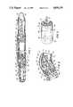
- FIG. 1is a cross-sectional view of a prosthesis according to the invention in its erect state.
- FIG. 2is a cross-sectional view of the valve system of FIG. 1.
- FIG. 3is a perspective view of the valve system of FIG. 1 taken along line 3--3 of FIG. 1.
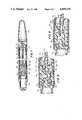
- FIG. 4is a cross-sectional view of a valve system according to the invention in the pressure phase of the pumping cycle.
- FIG. 5is a cross-sectional view of the valve system of FIG. 4 in the draw phase of the pumping cycle.
- FIG. 6is a cross-sectional view of the valve system of FIG. 4 in the first open or release position.
- FIG. 7is a cross-sectional view of a prosthesis according to the invention in its erect state.
- FIG. 8is a cross-sectional view of the valve system of FIG. 7 in the pumping position.
- FIG. 9is a cross-sectional view of the valve system of FIG. 7 in the release position.
- FIG. 1shows penile prosthesis 10 of the present invention comprising a generally tubular chamber 12 and fluid reservoir 14.
- Penile prosthesis 10is implanted within each of the two corpus cavernosa of the penis, although one penile prosthesis 10 may be implanted in either corpus cavernosum and still achieve useful results.
- All of the components of prosthesis 10are either composed of or covered by a biocompatible material such as silicone.
- Penile prosthesis 10has distal section 20 and proximal section 22.
- Proximal section 22is usually positioned in the rear of the corpus cavernosum under the puboischiatic rami.
- Proximal section 22defines the fluid reservoir 14.
- a rigid stabilizer 24extends rearwardly from the end of the tubular chamber 12 centrally through the fluid reservoir 14 to the rear tip 26. The stabilizer 24 serves to maintain the shape of the rear fluid reservoir 14 and provide rigidity regardless of the amount of fluid contained therein.
- a conventional rear tip extender(not shown) may be provided to lengthen prosthesis 10, if needed, to lessen the need for different prosthesis sizes.
- the distal section 20contains pump 28 which is manually actuatable for inflation of tubular chamber 12 which is located in series with respect to pump 28.
- the pump 28is advantageously a hollow circular chamber.
- the pump 28supplies fluid pressure by lateral squeezing of distal section 20.
- the ribs 30 and 32extend from the distal end of the valve system 34 to the front tip 36.
- the ribs 30 and 32serve the same purpose as stabilizer 24 in the fluid reservoir 14.
- the front tip 36is advantageously substantially rigid to resist buckling during intercourse.
- the tubular chamber 12is positioned within prosthesis 10 such that on implantation of prosthesis 10, the tubular chamber 12 lies approximately medially along the length of the corpus cavernosum.
- the manually actuatable valve system for controlling fluid flow between the tubular chamber 12 and the fluid reservoir 14comprises pump 28, pressure valve 38, suction valve 40, and release valve 42.
- the valve system in FIG. 1is in the second closed position.
- Pump 28is in fluid communication with pressure valve 38 and suction valve 40 to allow an irreversible fluid flow from fluid reservoir 14 to tubular chamber 12 on compressing and releasing the pump 28.
- Valves 38 and 40are located in distal section 20 in series with the tubular chamber 12 along the length of the prosthesis 10.
- the release valve 42includes cone 43 and valve block 45.
- the tubular chamber 12communicates with the fluid reservoir 14 when pressure is applied to the valve stem 47 so deforming valve block 45 which is made of a material such as rubber.
- valve block 45which is made of a material such as rubber.
- the suction valve 40communicates at its proximal end with a radially oriented passageway 44 which in turn communicates with a transverse, radially oriented passageway 46 which is generally perpendicular to passageway 44.
- the passageway 44communicates with an axial, lengthwise passageway 48.
- the passageway or conduit 48extends from the distal portion 20 to the proximal portion 22 in fluid isolation from the tubular chamber 12.
- the fluid of use in the prosthesisis a biocompatible fluid such as a physiological saline solution or a radio-opaque fluid.
- the tubular chamber 12has three different layers 50, 52 and 54.
- the outer layer 50 and the inner layer 54are formed of any material which is elastic such as silicone elastomer. Materials which may be used for the three layers are disclosed in above U.S. Pat. No. 4,267,829.
- the middle layer 52for instance, is made of a substantially non-distensible material such as a vascular graft material of Dacron® polyester fibers.
- the three layersmay be replaced by one layer having the desirable properties of non-distensibility and imperviousness to liquids.
- both valvesinclude a housing 56, a coiled spring 58 and a valve member 60.
- the coiled spring 58biases the valve member 60A of valve 40 proximally and the coiled spring 54 of valve 38 biases the valve member 60B distally.
- the valve systemcomprises the pump 28, the flap valve 62, the poppet valve 64, and the double flange valve 66.
- Pump 28communicates with fluid reservoir 14 through lumen 68, shown partially.
- the three valves 62, 64 and 66are positioned within tubular chamber 12, shown partially.
- Poppet valve 64has a coil spring 70 which biases poppet 72 proximally.
- the poppet 72seals against opening 74 when the coil spring 70 is extended.
- the double flange valve 66includes two flanges 76 and 78 which are held together by several spring retainers 80.
- O-ring seal 82 between flanges 76 and 78seals the two flanges 76 and 78 to prevent fluid flow between the two flanges when the double flange valve 66 is closed.
- the tubular chamber 12 partially shown in FIGS. 4 to 6generally has four different layers, as described below with reference to FIG. 7.
- FIGS. 7 to 9show a valve system comprising pump 28, pressure valve 38, suction valve 40, and bend valve 84.
- the pump 28 and the valves 38 and 40are as described above with reference to FIGS. 1 to 3.
- Tubular chamber 12is generally made of the three different layers 50, 52 and 54 described above.
- an inner tube 91made of a wear-resistant material such as polytetrafluoroethylene.
- the three layers 50, 52 and 54may be replaced by one layer.
- the pump 28communicates with the fluid reservoir 14 through the suction valve 40, the bend valve 84 and lumen 68.
- the bend valve 84includes a valve block 86 and a valve channel 88 which aligns with valve block passage 90 in FIGS. 7 and 8.
- the valve channel 88has a valve channel extension 94 which rests against a channel support block 92 in FIG. 9.
- the support block 92is made of a material such as rubber that is compressible by the extension 94 on bending the valve channel 88 relative to the valve block 86.
- the tubular chamber 12, the pump 28, and the fluid reservoir 14are supplied with biocompatible fluid by means known to those skilled in the art.
- Prosthesis 10is then implanted by surgical means known in the art. Once implanted, when an erection of the penis is to be produced, the user squeezes the distal section 20. On repeated squeezing and releasing of the distal section, fluid fills the tubular chamber 12 substantially to capacity and the desired stiffness and girth of prosthesis 10, and the penis, is attained.
- the userdeflates the prosthesis 10 by bending the penis at valve stem 47 as shown in FIG. 2, or by laterally squeezing prosthesis 10 at the valve block 45 as shown in FIG. 3.
- the bending or squeezingforces deform valve block 45 and allow fluid to flow from tubular chamber 12 past cone 43 through passageways 44 and 48 to fluid reservoir 14 (not shown) until the penis is flaccid.
- fluidflows from tubular chamber 12 past cone 43 through passageway 46 between outer layer 50 and middle layer 52 to passageway 48.
- the direction of the fluidis indicated by arrows in FIGS. 2 and 3.
- FIGS. 4 to 6in conjunction with FIG. 7, on squeezing distal section 20, fluid transfers from pump 28 through flap valve 62 into tubular chamber 12, as indicated by arrows in FIG. 4, showing the valve system in the second closed position.
- the poppet valve 64 and the double flange valve 66are closed preventing fluid flow through lumen 68 to fluid reservoir 14.
- the userthen releases distal section 20 creating a low pressure in pump 28 so opening poppet valve 64 and closing flap valve 62, and drawing fluid from fluid reservoir 14 through lumen 68 into pump 28, as indicated by arrows in FIG. 5 showing the valve system in the second closed position of the valve system during the draw phase of the pumping cycle.
- the userdeflates the prosthesis 10 by supporting the penis at a position proximal to double flange valve 66 and by bending distal section 20 such that spring retainers 80 are in a flexed position, and valve 66 opens.
- the user's actionforces the fluid under pressure in tubular chamber 12 to pass through open valve 66 and lumen 68 to the reservoir 14 until the penis is flaccid.
- the arrows in FIG. 6indicate the flow of fluid during the bending action.
- FIGS. 7 to 9on squeezing distal section 20, fluid transfers from pump 28 through pressure valve 38 to tubular chamber 12, as shown by broken arrows ( ⁇ ) in FIG. 8 showing the valve system in the second closed position during the pumping phase of the pumping cycle.
- the userthen releases distal section 20, creating a low pressure in pump 28 so opening suction valve 40, and drawing fluid from fluid reservoir 14 through central lumen 68, bend valve 84 and suction valve 40 into pump 28, as indicated by solid arrows in FIG. 8.
- the userdeflates the prosthesis 10 by bending the penis such that bend valve 84 is at an angle relative to valve block 86.
- the bending actionforces the fluid under pressure in tubular chamber 12 to pass between valve block 86 and bend valve 84 through central lumen 68 to fluid reservoir 14 until the penis is flaccid.
- the arrows in FIG. 9show the flow of fluid during bending when the valve system is in the first open position.
Landscapes
- Health & Medical Sciences (AREA)
- Reproductive Health (AREA)
- Cardiology (AREA)
- Oral & Maxillofacial Surgery (AREA)
- Transplantation (AREA)
- Engineering & Computer Science (AREA)
- Biomedical Technology (AREA)
- Heart & Thoracic Surgery (AREA)
- Vascular Medicine (AREA)
- Life Sciences & Earth Sciences (AREA)
- Animal Behavior & Ethology (AREA)
- General Health & Medical Sciences (AREA)
- Public Health (AREA)
- Veterinary Medicine (AREA)
- Prostheses (AREA)
Abstract
Description
Claims (11)
Priority Applications (4)
| Application Number | Priority Date | Filing Date | Title |
|---|---|---|---|
| US07/238,008US4895139A (en) | 1988-08-29 | 1988-08-29 | Inflatable penile prosthesis with bend release valve |
| EP89308582AEP0358380A1 (en) | 1988-08-29 | 1989-08-24 | Inflatable penile prothesis with bend release valve |
| CA000609420ACA1318468C (en) | 1988-08-29 | 1989-08-25 | Inflatable penile prosthesis with bend release valve |
| JP1221383AJPH0288055A (en) | 1988-08-29 | 1989-08-28 | Integrated pennis |
Applications Claiming Priority (1)
| Application Number | Priority Date | Filing Date | Title |
|---|---|---|---|
| US07/238,008US4895139A (en) | 1988-08-29 | 1988-08-29 | Inflatable penile prosthesis with bend release valve |
Publications (1)
| Publication Number | Publication Date |
|---|---|
| US4895139Atrue US4895139A (en) | 1990-01-23 |
Family
ID=22896106
Family Applications (1)
| Application Number | Title | Priority Date | Filing Date |
|---|---|---|---|
| US07/238,008Expired - LifetimeUS4895139A (en) | 1988-08-29 | 1988-08-29 | Inflatable penile prosthesis with bend release valve |
Country Status (4)
| Country | Link |
|---|---|
| US (1) | US4895139A (en) |
| EP (1) | EP0358380A1 (en) |
| JP (1) | JPH0288055A (en) |
| CA (1) | CA1318468C (en) |
Cited By (23)
| Publication number | Priority date | Publication date | Assignee | Title |
|---|---|---|---|---|
| US20040138523A1 (en)* | 2002-12-02 | 2004-07-15 | Ams Research Corporation | Implantable pump |
| US20040220447A1 (en)* | 2003-03-10 | 2004-11-04 | Morningstar Randy L. | Implantable penile prosthesis pump |
| US20050014993A1 (en)* | 2003-06-06 | 2005-01-20 | Mische Hans A. | Inflatable penile prosthesis with volume displacement materials and devices |
| US20050043581A1 (en)* | 2003-04-25 | 2005-02-24 | Ling Jeremy J. | Penile prosthesis with improved tubing junction |
| US20050113638A1 (en)* | 2003-10-02 | 2005-05-26 | Kuyava Charles C. | Implantable penile prosthesis pump |
| US20060135845A1 (en)* | 2004-12-17 | 2006-06-22 | Ams Research Corporation | Implantable penile prosthesis pump |
| US20090084447A1 (en)* | 2000-12-27 | 2009-04-02 | Ams Research Corporation | Diaphragm Based Spontaneous Inflation Inhibitor in a Pump for an Inflatable Prosthesis |
| US20090105530A1 (en)* | 2007-10-23 | 2009-04-23 | Ams Research Corporation | Corrugated Inflatable Penile Prosthesis Cylinder |
| US20090105818A1 (en)* | 2007-10-23 | 2009-04-23 | Ams Research Corporation | Malleable Prosthesis with Enhanced Concealability |
| US20090253953A1 (en)* | 2008-04-07 | 2009-10-08 | Coloplast A/S | Implantable fluid devices |
| US20090287042A1 (en)* | 2000-12-27 | 2009-11-19 | Ams Research Corporation | Penile Pump with Side Release Mechanism |
| WO2010016905A1 (en)* | 2008-08-08 | 2010-02-11 | Walch John R | Unitized penile erection system and tissue expander |
| US20100160723A1 (en)* | 2008-12-23 | 2010-06-24 | Kuyava Charles C | System to transport components of implantable penile prostheses |
| US7946975B2 (en) | 2005-04-08 | 2011-05-24 | Ams Research Corporation | Fluid reservoir for penile implant devices |
| US20110201880A1 (en)* | 2010-02-12 | 2011-08-18 | Fogarty Terence M | Inflatable penile prosthesis with spool valve |
| US8109870B2 (en) | 2006-11-10 | 2012-02-07 | Ams Research Corporation | Inflatable penile prosthesis bypass valve noise reduction |
| US8123674B2 (en) | 2007-11-12 | 2012-02-28 | Ams Research Corporation | Corrugated expansion-constraining sleeve for an inflatable penile prosthesis cylinder |
| US9084678B2 (en) | 2012-01-20 | 2015-07-21 | Ams Research Corporation | Automated implantable penile prosthesis pump system |
| US9474610B2 (en) | 2010-12-21 | 2016-10-25 | Boston Scientific Scimed, Inc. | Adjustable length rear tip extender for penile prosthesis |
| US9561107B2 (en) | 2014-12-04 | 2017-02-07 | Coloplast A/S | Base for a penile prosthetic implant and a penile prosthetic system |
| US10729546B2 (en) | 2017-02-02 | 2020-08-04 | Coloplast A/S | Inflatable penile prosthetic system |
| US11285006B2 (en) | 2018-04-09 | 2022-03-29 | Boston Scientific Scimed, Inc. | Inflatable penile prosthesis with valves for increasing flow efficiency |
| US11547566B2 (en) | 2019-08-06 | 2023-01-10 | Boston Scientific Scimed, Inc. | Inflatable penile prosthesis with guides in valve of pump assembly |
Families Citing this family (1)
| Publication number | Priority date | Publication date | Assignee | Title |
|---|---|---|---|---|
| WO2024258712A1 (en)* | 2023-06-13 | 2024-12-19 | Boston Scientific Scimed, Inc. | Implantable inflatable device |
Citations (10)
| Publication number | Priority date | Publication date | Assignee | Title |
|---|---|---|---|---|
| US3954102A (en)* | 1974-07-19 | 1976-05-04 | American Medical Systems, Inc. | Penile erection system and methods of implanting and using same |
| US4224934A (en)* | 1979-04-11 | 1980-09-30 | American Medical Systems, Inc. | Medical prosthetic pull valve and system for using same |
| US4267829A (en)* | 1979-04-11 | 1981-05-19 | American Medical Systems, Inc. | Penile prosthesis |
| US4353360A (en)* | 1980-10-31 | 1982-10-12 | Medical Engineering Corporation | Penile erectile system |
| US4369771A (en)* | 1981-09-24 | 1983-01-25 | Medical Engineering Corporation | Penile erectile system |
| US4449520A (en)* | 1982-09-02 | 1984-05-22 | Palomar Juan M | Penile prosthesis device |
| US4550719A (en)* | 1981-08-04 | 1985-11-05 | Medical Engineering Corporation | Implantable penile erectile system |
| US4590927A (en)* | 1985-02-25 | 1986-05-27 | American Medical Systems, Inc. | Unitary, inflatable penile prosthesis system |
| US4671261A (en)* | 1986-01-24 | 1987-06-09 | Fischell Robert | Penile erection device with valving in the penile cylinder |
| US4726360A (en)* | 1986-07-17 | 1988-02-23 | Medical Engineering Corporation | Penile prosthesis |
Family Cites Families (7)
| Publication number | Priority date | Publication date | Assignee | Title |
|---|---|---|---|---|
| US4407278A (en)* | 1981-05-15 | 1983-10-04 | American Medical Systems, Inc. | Penile prosthesis with improved fluid control |
| JPS5924824A (en)* | 1982-07-31 | 1984-02-08 | Toru Negishi | Multifocus glasses frame |
| US4566446A (en)* | 1983-04-08 | 1986-01-28 | Mentor Corporation | Penile prosthesis device |
| JPS6152147A (en)* | 1984-08-18 | 1986-03-14 | Omron Tateisi Electronics Co | Linear pulse motor |
| US4782826A (en)* | 1987-05-21 | 1988-11-08 | Mentor Corporation | Penile prosthesis |
| US4875472A (en)* | 1987-12-10 | 1989-10-24 | American Medical Systems, Inc. | Flat coil spring penile prosthesis |
| JP2638042B2 (en)* | 1988-02-27 | 1997-08-06 | タマ生化学株式会社 | Novel chlorin derivatives and tumor diagnostics |
- 1988
- 1988-08-29USUS07/238,008patent/US4895139A/ennot_activeExpired - Lifetime
- 1989
- 1989-08-24EPEP89308582Apatent/EP0358380A1/ennot_activeWithdrawn
- 1989-08-25CACA000609420Apatent/CA1318468C/ennot_activeExpired - Lifetime
- 1989-08-28JPJP1221383Apatent/JPH0288055A/enactivePending
Patent Citations (11)
| Publication number | Priority date | Publication date | Assignee | Title |
|---|---|---|---|---|
| US3954102A (en)* | 1974-07-19 | 1976-05-04 | American Medical Systems, Inc. | Penile erection system and methods of implanting and using same |
| US4224934A (en)* | 1979-04-11 | 1980-09-30 | American Medical Systems, Inc. | Medical prosthetic pull valve and system for using same |
| US4267829A (en)* | 1979-04-11 | 1981-05-19 | American Medical Systems, Inc. | Penile prosthesis |
| US4383525A (en)* | 1979-12-28 | 1983-05-17 | American Medical Systems, Inc. | Implantable penile prosthetic cylinder with inclusive fluid reservoir |
| US4353360A (en)* | 1980-10-31 | 1982-10-12 | Medical Engineering Corporation | Penile erectile system |
| US4550719A (en)* | 1981-08-04 | 1985-11-05 | Medical Engineering Corporation | Implantable penile erectile system |
| US4369771A (en)* | 1981-09-24 | 1983-01-25 | Medical Engineering Corporation | Penile erectile system |
| US4449520A (en)* | 1982-09-02 | 1984-05-22 | Palomar Juan M | Penile prosthesis device |
| US4590927A (en)* | 1985-02-25 | 1986-05-27 | American Medical Systems, Inc. | Unitary, inflatable penile prosthesis system |
| US4671261A (en)* | 1986-01-24 | 1987-06-09 | Fischell Robert | Penile erection device with valving in the penile cylinder |
| US4726360A (en)* | 1986-07-17 | 1988-02-23 | Medical Engineering Corporation | Penile prosthesis |
Cited By (42)
| Publication number | Priority date | Publication date | Assignee | Title |
|---|---|---|---|---|
| US20090084447A1 (en)* | 2000-12-27 | 2009-04-02 | Ams Research Corporation | Diaphragm Based Spontaneous Inflation Inhibitor in a Pump for an Inflatable Prosthesis |
| US20090287042A1 (en)* | 2000-12-27 | 2009-11-19 | Ams Research Corporation | Penile Pump with Side Release Mechanism |
| US8276591B2 (en) | 2000-12-27 | 2012-10-02 | Ams Research Corporation | Diaphragm based spontaneous inflation inhibitor in a pump for an inflatable prosthesis |
| US20040138523A1 (en)* | 2002-12-02 | 2004-07-15 | Ams Research Corporation | Implantable pump |
| US7874978B2 (en) | 2002-12-02 | 2011-01-25 | Ams Research Corporation | Implantable pump |
| US20050250982A1 (en)* | 2002-12-02 | 2005-11-10 | Kuyava Charles C | Implantable pump |
| US6991601B2 (en) | 2002-12-02 | 2006-01-31 | Ams Research Corporation | Implantable pump |
| US8062209B2 (en) | 2002-12-02 | 2011-11-22 | Ams Research Corporation | Implantable pump |
| US20110087068A1 (en)* | 2002-12-02 | 2011-04-14 | Ams Research Corporation | Implantable Pump |
| US20040220447A1 (en)* | 2003-03-10 | 2004-11-04 | Morningstar Randy L. | Implantable penile prosthesis pump |
| US7244227B2 (en) | 2003-03-10 | 2007-07-17 | Ams Research Corporation | Implantable penile prosthesis pump |
| US7169103B2 (en) | 2003-04-25 | 2007-01-30 | Ams Research Corporation | Penile prosthesis with improved tubing junction |
| US20050043581A1 (en)* | 2003-04-25 | 2005-02-24 | Ling Jeremy J. | Penile prosthesis with improved tubing junction |
| US7390296B2 (en) | 2003-06-06 | 2008-06-24 | Ams Research Corporation | Inflatable penile prosthesis with volume displacement materials and devices |
| US20050014993A1 (en)* | 2003-06-06 | 2005-01-20 | Mische Hans A. | Inflatable penile prosthesis with volume displacement materials and devices |
| US7250026B2 (en) | 2003-10-02 | 2007-07-31 | Ams Research Corporation | Implantable penile prosthesis pump |
| US20050113638A1 (en)* | 2003-10-02 | 2005-05-26 | Kuyava Charles C. | Implantable penile prosthesis pump |
| US20060135845A1 (en)* | 2004-12-17 | 2006-06-22 | Ams Research Corporation | Implantable penile prosthesis pump |
| US7637861B2 (en) | 2004-12-17 | 2009-12-29 | Ams Research Corporation | Implantable penile prosthesis pump |
| US7914439B2 (en) | 2004-12-17 | 2011-03-29 | Ams Research Corporation | Implantable penile prosthesis pump |
| US7946975B2 (en) | 2005-04-08 | 2011-05-24 | Ams Research Corporation | Fluid reservoir for penile implant devices |
| US8109870B2 (en) | 2006-11-10 | 2012-02-07 | Ams Research Corporation | Inflatable penile prosthesis bypass valve noise reduction |
| US8911350B2 (en) | 2007-10-23 | 2014-12-16 | Ams Research Corporation | Malleable prosthesis with enhanced concealability |
| US9517133B2 (en) | 2007-10-23 | 2016-12-13 | Boston Scientific Scimed, Inc. | Malleable prosthesis with enhanced concealability |
| US20090105818A1 (en)* | 2007-10-23 | 2009-04-23 | Ams Research Corporation | Malleable Prosthesis with Enhanced Concealability |
| US20090105530A1 (en)* | 2007-10-23 | 2009-04-23 | Ams Research Corporation | Corrugated Inflatable Penile Prosthesis Cylinder |
| US8114011B2 (en) | 2007-10-23 | 2012-02-14 | Ams Research Corporation | Corrugated inflatable penile prosthesis cylinder |
| US8123674B2 (en) | 2007-11-12 | 2012-02-28 | Ams Research Corporation | Corrugated expansion-constraining sleeve for an inflatable penile prosthesis cylinder |
| US7867162B2 (en) | 2008-04-07 | 2011-01-11 | Coloplast A/S | Implantable fluid devices |
| US20090253953A1 (en)* | 2008-04-07 | 2009-10-08 | Coloplast A/S | Implantable fluid devices |
| WO2010016905A1 (en)* | 2008-08-08 | 2010-02-11 | Walch John R | Unitized penile erection system and tissue expander |
| US20100160723A1 (en)* | 2008-12-23 | 2010-06-24 | Kuyava Charles C | System to transport components of implantable penile prostheses |
| US8702589B2 (en) | 2008-12-23 | 2014-04-22 | Ams Research Corporation | System to transport components of implantable penile prostheses |
| US20110201880A1 (en)* | 2010-02-12 | 2011-08-18 | Fogarty Terence M | Inflatable penile prosthesis with spool valve |
| US8241203B2 (en) | 2010-02-12 | 2012-08-14 | Fogarty Terence M | Inflatable penile prosthesis with spool valve |
| US9474610B2 (en) | 2010-12-21 | 2016-10-25 | Boston Scientific Scimed, Inc. | Adjustable length rear tip extender for penile prosthesis |
| US9084678B2 (en) | 2012-01-20 | 2015-07-21 | Ams Research Corporation | Automated implantable penile prosthesis pump system |
| US9808343B2 (en) | 2012-01-20 | 2017-11-07 | Boston Scientific Scimed, Inc. | Automated implantable penile prosthesis pump system |
| US9561107B2 (en) | 2014-12-04 | 2017-02-07 | Coloplast A/S | Base for a penile prosthetic implant and a penile prosthetic system |
| US10729546B2 (en) | 2017-02-02 | 2020-08-04 | Coloplast A/S | Inflatable penile prosthetic system |
| US11285006B2 (en) | 2018-04-09 | 2022-03-29 | Boston Scientific Scimed, Inc. | Inflatable penile prosthesis with valves for increasing flow efficiency |
| US11547566B2 (en) | 2019-08-06 | 2023-01-10 | Boston Scientific Scimed, Inc. | Inflatable penile prosthesis with guides in valve of pump assembly |
Also Published As
| Publication number | Publication date |
|---|---|
| JPH0288055A (en) | 1990-03-28 |
| EP0358380A1 (en) | 1990-03-14 |
| CA1318468C (en) | 1993-06-01 |
Similar Documents
| Publication | Publication Date | Title |
|---|---|---|
| US4895139A (en) | Inflatable penile prosthesis with bend release valve | |
| US5048510A (en) | Inflatable penile prosthesis with satellite reservoir | |
| EP0065853B1 (en) | Penile prosthesis with improved fluid control | |
| US4574792A (en) | Penile erectile system | |
| EP0193352B1 (en) | A unitary inflatable penile prosthesis | |
| US5704895A (en) | Implantable penile prosthetic cylinder with inclusive fluid reservoir | |
| EP0197787B1 (en) | Penile prosthesis system | |
| US5062417A (en) | Prosthesis with improved pump | |
| US4369771A (en) | Penile erectile system | |
| US4360010A (en) | Penile prosthesis | |
| US4898158A (en) | Penile implant with improved pressure relief valve | |
| US4364379A (en) | Penile erectile system | |
| US4399811A (en) | Implantable penile erectile system | |
| US4342308A (en) | Penile erectile system | |
| US4823779A (en) | Penile implant with compensator | |
| EP0428314B1 (en) | Implantable penile prothesis | |
| US5063914A (en) | Penile prosthesis | |
| US4682589A (en) | Penile prosthesis | |
| US4550719A (en) | Implantable penile erectile system | |
| US4457335A (en) | Penile erectile system | |
| US4995380A (en) | Penile prosthesis | |
| CA1317703C (en) | Flat coil spring penile prosthesis | |
| JPS5924824B2 (en) | implantable artificial penis | |
| JPS636018B2 (en) |
Legal Events
| Date | Code | Title | Description |
|---|---|---|---|
| AS | Assignment | Owner name:AMERICAN MEDICAL SYSTEMS, INC., 11001 BREN ROAD EA Free format text:ASSIGNMENT OF ASSIGNORS INTEREST.;ASSIGNORS:HAUSCHILD, SIDNEY F.;LEVIUS, DEZSO K.;REEL/FRAME:004954/0309 Effective date:19880801 Owner name:AMERICAN MEDICAL SYSTEMS, INC.,MINNESOTA Free format text:ASSIGNMENT OF ASSIGNORS INTEREST;ASSIGNORS:HAUSCHILD, SIDNEY F.;LEVIUS, DEZSO K.;REEL/FRAME:004954/0309 Effective date:19880801 | |
| FEPP | Fee payment procedure | Free format text:PAYOR NUMBER ASSIGNED (ORIGINAL EVENT CODE: ASPN); ENTITY STATUS OF PATENT OWNER: LARGE ENTITY | |
| STCF | Information on status: patent grant | Free format text:PATENTED CASE | |
| REMI | Maintenance fee reminder mailed | ||
| FPAY | Fee payment | Year of fee payment:4 | |
| SULP | Surcharge for late payment | ||
| FPAY | Fee payment | Year of fee payment:8 | |
| AS | Assignment | Owner name:WPAMS ACQUISITION CORP., NEW YORK Free format text:ASSIGNMENT OF ASSIGNORS INTEREST;ASSIGNOR:AMERICAN MEDICAL SYSTEMS, INC.;REEL/FRAME:010685/0496 Effective date:19980910 Owner name:AMERICAN MEDICAL SYSTEMS, INC., MINNESOTA Free format text:ASSIGNMENT OF ASSIGNORS INTEREST;ASSIGNOR:WPAMS ACQUISITION CORP.;REEL/FRAME:010685/0505 Effective date:19980702 | |
| AS | Assignment | Owner name:BANK OF AMERICA, N.A., AS AGENT, NORTH CAROLINA Free format text:NOTICE OF GRANT OF SECURITY INTEREST;ASSIGNOR:AMERICAN MEDICAL SYSTEMS, INC., F/K/A WPAMS ACQUISITION CORP.;REEL/FRAME:010795/0619 Effective date:20000417 | |
| FEPP | Fee payment procedure | Free format text:PAYER NUMBER DE-ASSIGNED (ORIGINAL EVENT CODE: RMPN); ENTITY STATUS OF PATENT OWNER: LARGE ENTITY Free format text:PAYOR NUMBER ASSIGNED (ORIGINAL EVENT CODE: ASPN); ENTITY STATUS OF PATENT OWNER: LARGE ENTITY | |
| FPAY | Fee payment | Year of fee payment:12 | |
| AS | Assignment | Owner name:BANK OF AMERICA, N.A., AS AGENT, NORTH CAROLINA Free format text:NOTICE OF GRANT OF SECURITY INTERST;ASSIGNOR:AMERICAN MEDICAL SYSTEMS, INC.;REEL/FRAME:014186/0257 Effective date:20000417 | |
| AS | Assignment | Owner name:AMS RESEARCH CORPORATION, MINNESOTA Free format text:ASSIGNMENT OF ASSIGNORS INTEREST;ASSIGNOR:AMERICAN MEDICAL SYSTEMS INC.;REEL/FRAME:013804/0172 Effective date:20030714 | |
| AS | Assignment | Owner name:AMERICAN MEDICAL SYSTEMS, INC., MINNESOTA Free format text:SECURITY INTEREST RELEASE;ASSIGNOR:BANK OF AMERICA, N.A.;REEL/FRAME:015596/0795 Effective date:20040701 | |
| AS | Assignment | Owner name:AMERICAN MEDICAL SYSTEMS, INC., MINNESOTA Free format text:RELEASE BY SECURED PARTY;ASSIGNOR:BANK OF AMERICA, N.A., AS AGENT;REEL/FRAME:017846/0709 Effective date:20060628 | |
| AS | Assignment | Owner name:AMERICAN MEDICAL SYSTEMS, INC. F/K/A WPAMS ACQUISI Free format text:RELEASE OF SECURITY INTEREST (SUPERCEDING RELEASE RECORDED ON JULY 30, 2004, AT REEL 015596, FRAME 0795).;ASSIGNOR:BANK OF AMERICA, N.A., AS AGENT;REEL/FRAME:017971/0028 Effective date:20060719 | |
| AS | Assignment | Owner name:AEMRICAN MEDICAL SYSTEMS, INC., MINNESOTA Free format text:RELEASE OF SECURITY INTEREST (SUPERCEEDING RELEASE RECORDED AT REEL/FRAME 017846/0709);ASSIGNOR:BANK OF AMERICA, N.A., AS AGENT;REEL/FRAME:018109/0700 Effective date:20060717 |