US4893248A - Monitoring and reporting system for remote terminals - Google Patents
Monitoring and reporting system for remote terminalsDownload PDFInfo
- Publication number
- US4893248A US4893248AUS07/011,976US1197687AUS4893248AUS 4893248 AUS4893248 AUS 4893248AUS 1197687 AUS1197687 AUS 1197687AUS 4893248 AUS4893248 AUS 4893248A
- Authority
- US
- United States
- Prior art keywords
- program
- time
- remote terminal
- pay per
- per view
- Prior art date
- Legal status (The legal status is an assumption and is not a legal conclusion. Google has not performed a legal analysis and makes no representation as to the accuracy of the status listed.)
- Expired - Lifetime
Links
Images


Classifications
- H—ELECTRICITY
- H04—ELECTRIC COMMUNICATION TECHNIQUE
- H04N—PICTORIAL COMMUNICATION, e.g. TELEVISION
- H04N7/00—Television systems
- H04N7/16—Analogue secrecy systems; Analogue subscription systems
- H04N7/173—Analogue secrecy systems; Analogue subscription systems with two-way working, e.g. subscriber sending a programme selection signal
- H04N7/17309—Transmission or handling of upstream communications
- H04N7/17327—Transmission or handling of upstream communications with deferred transmission or handling of upstream communications
- G—PHYSICS
- G06—COMPUTING OR CALCULATING; COUNTING
- G06Q—INFORMATION AND COMMUNICATION TECHNOLOGY [ICT] SPECIALLY ADAPTED FOR ADMINISTRATIVE, COMMERCIAL, FINANCIAL, MANAGERIAL OR SUPERVISORY PURPOSES; SYSTEMS OR METHODS SPECIALLY ADAPTED FOR ADMINISTRATIVE, COMMERCIAL, FINANCIAL, MANAGERIAL OR SUPERVISORY PURPOSES, NOT OTHERWISE PROVIDED FOR
- G06Q30/00—Commerce
- G06Q30/02—Marketing; Price estimation or determination; Fundraising
- G06Q30/0283—Price estimation or determination
- H—ELECTRICITY
- H04—ELECTRIC COMMUNICATION TECHNIQUE
- H04H—BROADCAST COMMUNICATION
- H04H60/00—Arrangements for broadcast applications with a direct linking to broadcast information or broadcast space-time; Broadcast-related systems
- H04H60/35—Arrangements for identifying or recognising characteristics with a direct linkage to broadcast information or to broadcast space-time, e.g. for identifying broadcast stations or for identifying users
- H04H60/38—Arrangements for identifying or recognising characteristics with a direct linkage to broadcast information or to broadcast space-time, e.g. for identifying broadcast stations or for identifying users for identifying broadcast time or space
- H04H60/41—Arrangements for identifying or recognising characteristics with a direct linkage to broadcast information or to broadcast space-time, e.g. for identifying broadcast stations or for identifying users for identifying broadcast time or space for identifying broadcast space, i.e. broadcast channels, broadcast stations or broadcast areas
- H04H60/44—Arrangements for identifying or recognising characteristics with a direct linkage to broadcast information or to broadcast space-time, e.g. for identifying broadcast stations or for identifying users for identifying broadcast time or space for identifying broadcast space, i.e. broadcast channels, broadcast stations or broadcast areas for identifying broadcast stations
- H—ELECTRICITY
- H04—ELECTRIC COMMUNICATION TECHNIQUE
- H04N—PICTORIAL COMMUNICATION, e.g. TELEVISION
- H04N21/00—Selective content distribution, e.g. interactive television or video on demand [VOD]
- H04N21/20—Servers specifically adapted for the distribution of content, e.g. VOD servers; Operations thereof
- H04N21/25—Management operations performed by the server for facilitating the content distribution or administrating data related to end-users or client devices, e.g. end-user or client device authentication, learning user preferences for recommending movies
- H04N21/254—Management at additional data server, e.g. shopping server, rights management server
- H04N21/2543—Billing, e.g. for subscription services
- H—ELECTRICITY
- H04—ELECTRIC COMMUNICATION TECHNIQUE
- H04N—PICTORIAL COMMUNICATION, e.g. TELEVISION
- H04N21/00—Selective content distribution, e.g. interactive television or video on demand [VOD]
- H04N21/20—Servers specifically adapted for the distribution of content, e.g. VOD servers; Operations thereof
- H04N21/25—Management operations performed by the server for facilitating the content distribution or administrating data related to end-users or client devices, e.g. end-user or client device authentication, learning user preferences for recommending movies
- H04N21/258—Client or end-user data management, e.g. managing client capabilities, user preferences or demographics, processing of multiple end-users preferences to derive collaborative data
- H04N21/25808—Management of client data
- H04N21/25816—Management of client data involving client authentication
- H—ELECTRICITY
- H04—ELECTRIC COMMUNICATION TECHNIQUE
- H04N—PICTORIAL COMMUNICATION, e.g. TELEVISION
- H04N21/00—Selective content distribution, e.g. interactive television or video on demand [VOD]
- H04N21/20—Servers specifically adapted for the distribution of content, e.g. VOD servers; Operations thereof
- H04N21/25—Management operations performed by the server for facilitating the content distribution or administrating data related to end-users or client devices, e.g. end-user or client device authentication, learning user preferences for recommending movies
- H04N21/258—Client or end-user data management, e.g. managing client capabilities, user preferences or demographics, processing of multiple end-users preferences to derive collaborative data
- H04N21/25866—Management of end-user data
- H04N21/25875—Management of end-user data involving end-user authentication
- H—ELECTRICITY
- H04—ELECTRIC COMMUNICATION TECHNIQUE
- H04N—PICTORIAL COMMUNICATION, e.g. TELEVISION
- H04N21/00—Selective content distribution, e.g. interactive television or video on demand [VOD]
- H04N21/40—Client devices specifically adapted for the reception of or interaction with content, e.g. set-top-box [STB]; Operations thereof
- H04N21/43—Processing of content or additional data, e.g. demultiplexing additional data from a digital video stream; Elementary client operations, e.g. monitoring of home network or synchronising decoder's clock; Client middleware
- H04N21/442—Monitoring of processes or resources, e.g. detecting the failure of a recording device, monitoring the downstream bandwidth, the number of times a movie has been viewed, the storage space available from the internal hard disk
- H04N21/44204—Monitoring of content usage, e.g. the number of times a movie has been viewed, copied or the amount which has been watched
- H—ELECTRICITY
- H04—ELECTRIC COMMUNICATION TECHNIQUE
- H04N—PICTORIAL COMMUNICATION, e.g. TELEVISION
- H04N21/00—Selective content distribution, e.g. interactive television or video on demand [VOD]
- H04N21/40—Client devices specifically adapted for the reception of or interaction with content, e.g. set-top-box [STB]; Operations thereof
- H04N21/47—End-user applications
- H04N21/472—End-user interface for requesting content, additional data or services; End-user interface for interacting with content, e.g. for content reservation or setting reminders, for requesting event notification, for manipulating displayed content
- H04N21/47211—End-user interface for requesting content, additional data or services; End-user interface for interacting with content, e.g. for content reservation or setting reminders, for requesting event notification, for manipulating displayed content for requesting pay-per-view content
- H—ELECTRICITY
- H04—ELECTRIC COMMUNICATION TECHNIQUE
- H04N—PICTORIAL COMMUNICATION, e.g. TELEVISION
- H04N21/00—Selective content distribution, e.g. interactive television or video on demand [VOD]
- H04N21/40—Client devices specifically adapted for the reception of or interaction with content, e.g. set-top-box [STB]; Operations thereof
- H04N21/47—End-user applications
- H04N21/488—Data services, e.g. news ticker
- H04N21/4882—Data services, e.g. news ticker for displaying messages, e.g. warnings, reminders
- H—ELECTRICITY
- H04—ELECTRIC COMMUNICATION TECHNIQUE
- H04N—PICTORIAL COMMUNICATION, e.g. TELEVISION
- H04N21/00—Selective content distribution, e.g. interactive television or video on demand [VOD]
- H04N21/60—Network structure or processes for video distribution between server and client or between remote clients; Control signalling between clients, server and network components; Transmission of management data between server and client, e.g. sending from server to client commands for recording incoming content stream; Communication details between server and client
- H04N21/65—Transmission of management data between client and server
- H04N21/658—Transmission by the client directed to the server
- H04N21/6582—Data stored in the client, e.g. viewing habits, hardware capabilities, credit card number
- H—ELECTRICITY
- H04—ELECTRIC COMMUNICATION TECHNIQUE
- H04N—PICTORIAL COMMUNICATION, e.g. TELEVISION
- H04N21/00—Selective content distribution, e.g. interactive television or video on demand [VOD]
- H04N21/80—Generation or processing of content or additional data by content creator independently of the distribution process; Content per se
- H04N21/83—Generation or processing of protective or descriptive data associated with content; Content structuring
- H04N21/835—Generation of protective data, e.g. certificates
- H04N21/8355—Generation of protective data, e.g. certificates involving usage data, e.g. number of copies or viewings allowed
- H—ELECTRICITY
- H04—ELECTRIC COMMUNICATION TECHNIQUE
- H04N—PICTORIAL COMMUNICATION, e.g. TELEVISION
- H04N7/00—Television systems
- H04N7/16—Analogue secrecy systems; Analogue subscription systems
- H—ELECTRICITY
- H04—ELECTRIC COMMUNICATION TECHNIQUE
- H04H—BROADCAST COMMUNICATION
- H04H2201/00—Aspects of broadcast communication
- H04H2201/30—Aspects of broadcast communication characterised by the use of a return channel, e.g. for collecting users' opinions, for returning broadcast space/time information or for requesting data
- H—ELECTRICITY
- H04—ELECTRIC COMMUNICATION TECHNIQUE
- H04H—BROADCAST COMMUNICATION
- H04H60/00—Arrangements for broadcast applications with a direct linking to broadcast information or broadcast space-time; Broadcast-related systems
- H04H60/76—Arrangements characterised by transmission systems other than for broadcast, e.g. the Internet
- H04H60/81—Arrangements characterised by transmission systems other than for broadcast, e.g. the Internet characterised by the transmission system itself
- H04H60/93—Wired transmission systems
- H04H60/94—Telephonic networks
- H—ELECTRICITY
- H04—ELECTRIC COMMUNICATION TECHNIQUE
- H04N—PICTORIAL COMMUNICATION, e.g. TELEVISION
- H04N7/00—Television systems
- H04N7/16—Analogue secrecy systems; Analogue subscription systems
- H04N7/173—Analogue secrecy systems; Analogue subscription systems with two-way working, e.g. subscriber sending a programme selection signal
- H04N2007/1739—Analogue secrecy systems; Analogue subscription systems with two-way working, e.g. subscriber sending a programme selection signal the upstream communication being transmitted via a separate link, e.g. telephone line
Definitions
- This inventionrelates to a secure system comprise of a plurality of remote terminals and at least one central station for receiving data monitored and reported by each of the remote terminals.
- this inventionrelates in one illustrative embodiment thereof to a system of remote terminals, which monitors and accumulates data relating to pay per view television programs that have been authorized at the remote terminal and, thereafter, reports such program data in a secure fashion as will prevent potential interference or interception by a viewer at the remote terminal.
- a terminalis disposed with sensors or monitors particularly adapted for monitoring an activity at that remote location, storing the monitored data and subsequently reporting the accumulated data on a periodic basis to a centrally disposed station.
- a host computeris typically disposed at the central station for receiving reports from each of the remote terminals and for using the reported data to bill the customer for the rendered services or consumption.
- this secure systemrelates to a pay per view television (TV) system which monitors each TV program that a viewer at the remote terminal authorizes and, thereafter, reports to the host computer data indicative of the authorized programs and a code identifying the remote terminal and viewer.
- TVpay per view television
- Real time systemsrequire that a prospective viewer must first place an order with the central station to authorize the selected program.
- a preordermay be placed over a conventional, non-dedicated telephone line or a dedicated cable interconnecting the remote terminal and the central station.
- the central stationresponds to the preorder and forwards an enabling message addressed the particular remote terminal from which the selected program was ordered.
- the host computer at the central stationmust perform a credit check and, if good, download the viewer s telephone and account numbers to an addressable controller, which in turn transmits the enabling message to the ordering remote terminal.
- Such real time systemsmay be further streamlined by employing an auto-dialer at the remote terminal, whereby the order is automatically transmitted to the central station.
- Alternative to the use of conventional telephone transmission linesis the use of two-way cable systems, which are capable of transmitting TV program orders at an exceptionally high speed from the remote terminal to the central station. The improved capability of these real time systems is achieved at greater and greater expense as automated apparatus is employed at the remote terminals and at the central station, or as a two-way cable system is employed instead of a conventional telephone transmission line.
- a decoding or descraming apparatus at the remote terminalauthorizes or permits access to the selected pay per view TV program as transmitted to the r ⁇ mote terminal on a cable.
- the viewermay authorize a selected TV program and have it immediately descrambled and available for viewing without delaying to communicate with the central station.
- data identifying the selected pay per view TV programis stored in the terminal's memory.
- the remote terminaltransmits a report message to the central station by a second cable, or by a conventional telephone transmission line.
- Examples of non-real time pay per view TV systemsare provided by U.S. Pat. No. 4,361,851 of Asip et al. and U.S. Pat. No. 4,104,486 of Martin et al.
- the Asip et al. systemis implemented by a microprocessor, and a memory for storing the time of day and channel identification of an authorized pay per view TV program.
- the Asip et al. systemalso includes a telephone interface for determining if the viewer's telephone is in use or free. At selected times controlled by a real-time clock, the remote terminal of Asip et al. initiates a call to a central station to report periodically the programs authorized by the viewer.
- the remote terminalwill initiate a call at a later time when the viewer's telephone is free.
- Each remote terminal and its viewerhave a unique identity code, whereby the viewer may be billed.
- the host computer at the central stationmay transmit control messages to the remote terminal, e.g., transmit a message to deactuate the remote terminal if the viewer has not paid his/her bill.
- the Asip et al. systemalso includes a 24 hour real time clock that is used to transmit at predetermined intervals a report message including data indicative of the authorized program(s) and the identity code of the remote terminal to the central station.
- Asip et al.employs a transient or buffer memory for storing program authorization data and a timer in the form of a software timing loop that upon timing out causes the transfer of the program authorization data from the buffer memory, if still there, to a second memory, from which it may be transmitted to the central station.
- the Martin et al. patent '486also relates to a remote terminal for monitoring and accumulating data pertaining to the pay per view TV programs accessed at a remote terminal identified by a unique code.
- the remote terminaltransmits a message reporting program data to a central station over non-dedicated telephone lines.
- a host computer at the central stationreceives these report messages and generates bills in accordance with the authorized programs.
- a telephone dialing apparatusthat upon command of a preconditioning circuit seizes a telephone line and transmits the report message.
- the preconditioning circuitincludes one or more timers, each of which generates an output pulse at predetermined timed periodic bases, e.g., every two weeks or once a month. The output pulses serve to precondition the telephone dialing apparatus to in turn report the accumulated pay per view program data.
- non-real time systemis its ability to accommodate the impulse viewer, who at a time immediately prior to or at the beginning of a pay per view TV program wishes to authorize the viewing of that program.
- a non-real time programsimply records the authorized program and reports that program and the unique code of the remote terminal at a later time to the central terminal for billing purposes.
- a significant problem associated with non-real time systemsrelates to attempts to defeat the reporting of authorized pay per view TV programs at a later time by tampering with the remote terminal.
- Typical of such attemptsis the removal of power from the remote terminal as by unplugging the power line in the hopes that the remote terminal will be able to neither store data indicative of the authorized pay per view TV program, nor at a subsequent time to transmit a message reporting the accumulated pay per view program data to the central station.
- Efforts to secure a remote terminal from attempts to prevent accurate reportingare further complicated by the desire to provide the viewer with a preview of a particular pay per view TV program, before the viewer is charged for that program.
- the viewerwill select that channel on which a pay per view TV program will or is currently appearing.
- the viewerwill actuate his/her remote terminal to authorize and to descramble the program signal so that it will be displayed as an unscrambled image upon the viewer's TV set. It is desired to provide a grace or preview period of a relatively short interval in which the viewer may decide whether he/she wants to watch that program.
- the viewerwill deactuate the remote terminal, otherwise if the viewer continues to watch the program, the pay per vie TV program will be recorded and, subsequently, a report message will be forwarded to the central station reporting the authorizing and viewing of that pay per view TV program.
- the Martin et al. patent '486, described above,implemented such a preview by using a temporary or buffer memory for storing a signal indicative of a pay per view TV program and if present in the buffer memory after a predetermined interval, that signal was loaded to a memory from which it would be transmitted as a return message to the central station.
- a viewercould use the knowledge of the length of such a preview interval to defeat the reporting of the TV program, by repeatedly authorizing and deauthorizing a particular pay per view TV program within the preview interval throughout the entire length of the program without having triggered the downloading of the pay per view TV program signal from the buffer memory of Martin et al. and, therefore, to avoid the reporting and billing for the viewed pay per view TV program.
- a further scheme to defeat reporting of a viewed pay per view TV programinvolves the authorization on the remote terminal of a pay per view TV program and, thereafter, removing power from the remote terminal before the end of the preview interval.
- the viewerwill be informed of the length of the preview time by the source or promoter of the pay per view TV programs.
- the removal of power from the remote terminalmay defeat the termination of the preview period, the generation or downloading of a signal indicating that the viewer should be charged for the authorized TV program and/or the transmission of a report message from the remote terminal to the central station.
- Viewersmay also attempt to avoid payment for authorized programs by disconnecting the remote terminal from their non-dedicated telephone line.
- a remote terminalsuch as disclosed by the Martin et al. patent '486, which transmits report messages on a predetermined periodic basis, could be easily defeated by first ascertaining such periodic basis and disconnecting the viewer's telephone from the remote terminal at those times.
- a viewer intending to avoid payment for authorized programsmay attempt to intercept the report message to ascertain the format and content of the message, whereby such a report message could be altered to reflect no authorized pay per view TV programs.
- a system for monitoring and accumulating data indicative of viewer authorized pay per view TV programs at each of a plurality of remote terminalswherein each remote terminal is coupled illustratively by non-dedicated telephone lines to a host computer at a central station.
- the remote terminalincludes viewer actuable means for authorizing the viewing of a pay per TV program, a memory, means responsive to the authorizing of a program for storing data indicative of the authorized programs into the memory, and means responsive to the authorizing of the pay per view TV program for transmitting over the telephone lines to the host computer a report message including the program data.
- a randomly calculated call-in timeis set from the end of the program or the deauthorizing of the program.
- Security featuresare adopted for the remote terminal of this invention to prevent viewer interference with the monitoring and/or reporting of the report message to the host computer as by removing energization from the remote terminal and/or disconnecting the telephone lines from the remote terminal.
- a batteryprovides backup energization to the memory and to a real time clock if normal energization is removed.
- An expected end of program timeis calculated at the time of authorization by calculating the sum of the current real time and a period set according to the known length of the program. When the calculated end of show time has been reached as by comparison with the real time clock, the authorized pay per view TV program is deauthorized.
- the power-on timeis compared with the calculated end of show time and, if greater by a predetermined period, the power-on time is adopted as the end of show time. Further, the time of a power outage, i.e., the power-off time, is noted and stored in a memory, so that upon restoration of energy to the remote terminal, the power-on time can be noted and the length of the power outage calculated as the difference between the power-on and power-off times.
- the remote terminalis provided with means for deauthorizing a previously authorized pay per view TV program and for recording that time of deauthorizing.
- the viewermay be given a preview period of an authorized pay per view program, whereby the viewer will be billed for that program only if the viewer views the authorized program for a time greater than the preview period.
- the time of each authorizing and deauthorizingis noted and stored in memory, whereby each viewing segment between successive authorizing and deauthorizings may be calculated and stored in a total viewing time memory.
- the number of deauthorizationsmay be counted and included with the total viewing time within the report message, which will be transmitted at the call-in time to the host computer.
- each vieweris given a credit limit illustratively as the number of pay per view TV programs that will be authorized before it is necessary to update that credit limit.
- the remote terminalat call-in time transmits a report message to the host computer, which checks the viewer's credit and, if satisfactory, transmits or downloads a new credit limit to the remote terminal, thus permitting further authorizing of pay per view programs.
- the remote terminalforms counters in its memories, which are incremented upon sensing no-dial tone, each attempted transmission or dialing to the host computer or the sensing of a busy signal derived from the host computer.
- the remote terminaldefeats the further authorizing of pay per view programs.
- the remote terminalhas the capacity for self-initialization, whereby data indicative of the credit limit and other data as related to the viewing of pay per view TV programs, may be downloaded from an initializing computer.
- Each remote terminalhas stored therein a telephone number of the initializing computer and is adapted upon being first energized for accessing that number and sending a message over conventional telephone lines, requesting the downloading of the initializing data from the initializing computer.
- the remote terminalis adapted to periodically examine the initialization data and, if it is lost or becomes defective, to transmit a request message to the initializing computer.
- a request messagemay also be transmitted to the initializing computer, if the remote terminal is unable to connect over the telephone lines with its host computer, e.g., the remote terminal has tried a predetermined number of times without succeeding to place a telephone call to its host computer.
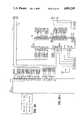
- FIGS. 1A and 1Bare respectively a functional block diagram of a remote terminal of the monitoring and reporting system in accordance with the teachings of this invention, and a perspective view of its converter;
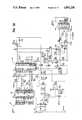
- FIGS. 2A-1 to A-4, 2B and 2Care detailed, schematic drawings of the remote terminal as shown in FIG. 1A, and FIG. 2A shows how FIGS. 2A-1 to 2A-4 are assembled with respect to each other; and
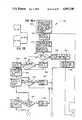
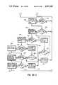
- FIGS. 3A-1 to 3A-4, 3B-I to 3B-3, 3C, 3A and 3Bare respectively flow diagrams of a main program, a more detailed flow diagram of an uploading/downloading subroutine of the main routine, an initialization subroutine, a showing of how FIGS. 3A-1 to 3A-4 are assembled with respect to each other, and how FIGS. 3B-1 to 3B-3 are assembled with respect to each other, all of the programs and subroutines being stored in a ROM and executed by a microprocessor of the remote terminal as illustrated in FIGS. 1A and 2A-1 to 2A-4.
- FIG. 1Athere is shown a functional block diagram of a remote terminal 10 incorporated in a secure monitoring and reporting system in accordance with the teachings of this invention.
- the remote terminal 10is coupled by ordinary telephone lines 18 to a central station 11, whereat there is disposed a host computer for receiving report messages from the remote terminal 10.
- the remote terminal 10is adapted to monitor and report pay per view TV programs as are authorized by a viewer at the remote terminal 10.
- TV programsare transmitted via a coax cable 12 in an encoded, scrambled or encrypted fashion to a converter 14, which decodes, descrambles or decrypts the transmitted TV program to permit viewing of an undistorted image on a conventional television receiver or set 16.
- a converter 14which decodes, descrambles or decrypts the transmitted TV program to permit viewing of an undistorted image on a conventional television receiver or set 16.
- Such encryptionrenders it difficult for an unauthorized viewer to receive the TV program transmitted on the coax cable 12 and to display the normal video and audio portions of the TV program.
- the converter 14may take the form of that converter as manufactured by Pioneer Communications Of America, Inc. under their model number BA-5000.
- FIG. 1Bthere is shown a perspective view of the converter 14 in the illustrative form of the model BA-5000, including a remote control unit 15 with a plurality of switches or buttons on a panel 17 for actuating/deactuating the various functions of the converter 14.
- the converter 14includes a similar control in the form of a key pad 19 disposed upon the top of the converter 14 and including a plurality of buttons 21. Buttons on the panels 17 and 19 with similar designations operate like functions. For example, the 0-9 buttons permit viewer entry of a particular channel or entry of the viewer's code number.
- the on/off button on the panel 17permits the turning on or off the remote terminal 14.
- the # button on the panel 17permits the viewer to cancel or deauthorize a Tv program after it has been authorized.
- the AUTH button on the panel 17permits the viewer to authorize a particular pay per view TV program.
- the pay-per-view channelhad been previously set by pushing selected of the 0-9 buttons on the panel 17.
- the actuation of the AUTH button on the panel 17accesses a pay per view program and causes the converter 14 to decrypt the Tv program signal as transmitted via coax cable 12.
- a channel/response C/R button on the panel 17permits selection of either the channel or response mode. In the channel mode, the viewer may choose either a free or pay per view program as by selecting the right channel. In the response mode, the converter 14 may be used for other functions such as ordering merchandise as may be displayed upon the television set 16 or providing response to questions as displayed upon the television set 16.
- the TIM button on the panel 17actuates the converter 14 to turn on and/or shut off at predetermined times, whereby TV programs may be viewed and/or recorded at predetermined times in the future.
- the turn on and shut off timesare stored by actuating the 0-9 buttons on the panel 17 and then actuating the TIM button on the panel 17.
- the entered timesmay be then stored in the converter 14 by actuating the store (STR) button.
- the (CLR) button on the panel 17is depressed.
- Entered turn on and shut off timesmay be displayed by depressing the recall (RCL) button on the panel 17.
- the PC button on a panel 21 on the key pad 19permits a viewer to prevent actuation of certain pay per view or other designated channels.
- terminals 25 for the converter 14For example, terminal 25a interconnects the converter 14 and the television set 16. Terminals 25b permit connection with one or more coax cables 12. Switch 25c is a parental control lock switch which may be physically held as by a pad lock to prevent access to selected pay per view or other designated channels. Terminal 25d provides an AC convenience power outlet. Energization in the form of conventional AC power is applied via line 25e to the converter 14.
- the converter 14is coupled to the remote terminal 10 and, in particular, to its data buffer 20, which is backed up by a battery. As indicated by the arrows shown in FIG. 1A, the data flow between the data buffer 20 and the converter 14 is bi-directional. As illustrated in FIG. 1A, a back-up battery 46 is employed to energize the data buffer 20, even if normal power is removed from the remote terminal 10, e.g., the power line 25e is unplugged. Without such a battery back-up 46, if power were removed from the data buffer 20, it might impose an undue load upon the converter 14 causing it to malfunction. It is desired that the converter 14 operate conventionally whether the remote terminal 10 is powered or not.
- the data buffer 20receives from the converter 14 data indicative of the authentication of a particular pay per view TV program, the cancellation of a previously authorized TV program, input data indicative of the code as entered upon the 0-9 buttons on the panel 17 of the remote control unit 15, the particular channel or pay per view TV program authorized and other data as indicative of an authorization made by the viewer. Data is also received from the data buffer 20 by the converter 14, to control the operation of the converter 14. As will be explained later, there are a number of situations in which the remote terminal 10 will defeat the operation of the converter 14. For example, the viewer will be assigned a "credit limit" corresponding to the number of pay per view TV programs that the viewer will be permitted to authorize before it is necessary to communicate with the central station 11.
- the remote terminal 10will instruct the converter 14 to disable further viewing of pay per view TV programs, while permitting the viewing of the free TV programs.
- the remote terminal 10can instruct the converter 14 to defeat viewing of all TV programs under certain circumstances such as where it has been determined that the viewer has attempted to defeat the monitoring and/or reporting functions of the remote terminal 10.
- the remote terminal 10is shown generally in the functional block diagram of FIG. 1A and in detail in the circuit schematic diagrams of FIGS. 2A, 2B and 2C. It will be appreciated that the functional block diagram of FIG. 1A will be shown in FIGS. 2 in the form of corresponding digital circuits or by sub circuits of elements and digital chips as enclosed within dotted lines, corresponding functions and elements being identified by like numbers.
- the remote terminal 10includes a microprocessor having address terminals A0-A15 and data terminals D0-D7 coupled respectively by an address bus 58 and a data bus 56 to each of a parallel input-output interface 26, a random access memory (RAM) 38 and a read only memory (ROM) 34, as shown in FIGS.
- the serial interface 36is coupled to the parallel data terminals of the microprocessor 24 and converts the parallel data received from the microprocessor 24 into serial data to be applied to a modem 44.
- the serial interface 36receives serial data from the modem 44 and converts it to parallel data to be applied to the microprocessor 24.
- Serial datais interchanged between the modem 44 and a digital acquisition adapter (DAA) 48 as is directly connected to the telephone lines 18 for receiving "RING" and "TIP" signals as are imposed upon the conventional telephone lines 18.
- DAAdigital acquisition adapter
- the call progress circuit 42is coupled to the input lines of the DAA 48 to apply a signal to the microprocessor 24, indicative of incoming data so as to inhibit the generation of output data from the microprocessor 24.
- a pair of operational amplifiers 60a and 60bamplify the signal appearing on the telephone lines 18 and applies the amplified signal respectively to the modem 44 and the call progress circuit 42.
- computer programs to be executed by the microprocessor 24are stored in the ROM 34.
- the back-up battery 46energizes not only the data buffer 20, but also the RAM 38 and a real time clock 40 in the event that normal energization is removed as by unplugging the remote terminal 10.
- the back-up battery 46provides security against attempts by the viewer to defeat the monitoring and storage of pay per view TV programs by disconnecting the power line 25e.
- the continued energization of the RAM 38insures that stored data indicative of authorized pay per view TV programs will be retained for later reporting, while the real time clock 40 continues to be energized to provide a signal or manifestation of the current time, which permits timing of certain events (as will be explained in detail later) that will provide an indication of viewer attempts to defeat the monitoring and reporting of pay per view TV programs.
- the non-volatile memory comprised of the RAM 38 and the back-up battery 46may be replaced with an electrically erasable programmable read only memory (EEPROM) or an electrically alterable read only memory (EAROM).
- EEPROMelectrically erasable programmable read only memory
- a parallel input/output interface 26interconnects the flow of data between the microprocessor 24 and the data buffer 20 to insure the orderly transfer of data in but one direction at a time.
- a frequency shift key (F.S.K.) data switch 28is inserted between the data buffer 20 and the parallel I/O interface 26.
- the remote terminal 10 and the converter 14may be incorporated in a system including a source of pay per view programs that also transmits upon a separate non-video channel of the cable input 12 F.S.K. command or control signals similar to that provided by the remote terminal 10.
- the remote terminal 10has the capability through its F.S.K. data switch 28 either to receive such F.S.K.
- the channel data register 22is responsive to that phase lock loop (PLL) channel data as derived from the converter 14 and indicative to the channel to which the converter 14 is set, to supply such data to the microprocessor 24.
- PLLphase lock loop
- a watchdog timer 30provides a regular reset signal to the microprocessor 24, e.g., every minute, if a defeat signal is not generated in each cycle of the execution of a main program 110 (as will be explained with respect to FIG. 3A) by the microprocessor 24 and applied via the interface 26 to defeat the timing function of the watchdog timer 30.
- the periodic reset signal from the watchdog timer 30will reset the microprocessor 24 returning the execution of the main program 110 to its initial instruction.
- a 2 MHz oscillator 32applies its clock signal to effect required timing functions of the microprocessor 24.
- a reset circuit 50is responsive to the application of power to the remote terminal 10 and by the coupling of the power line 25e, to time a delay before releasing reset signal to the reset terminal of the microprocessor 24, thus permitting the power level as applied to the elements of the remote terminal 10 to stabilize before initiating its operation.
- a DATA MUX 54is responsive to address signals applied via the address bus 58 to enable and selectively address one of the parallel input/output interface 26, the channel data register 22, the real time clock 40, the call progress circuit 42 or the serial interface 36 to transmit data with the microprocessor 24 via the data bus 56.
- a memory select 52is responsive to signals from the microprocessor 24 to control whether data is read from the RAM 38 or the ROM 34.
- a power supply 62as coupled via the line terminal 25e to a conventional AC power source, for providing regulated levels of voltage, e.g., plus and minus 5VDC.
- the data buffer 20is coupled via a transistor Q1 to the regulated output of the power supply 62 and is responsive to the removal of the regulated +5V, to disable the data buffer 20.
- a 3.58 MHz oscillator 64supplies its clock signal to the modem 44 and to the call progress circuit 42.
- step 114searches for any input from the remote control unit 15 of the converter 14, as would be entered by actuating selected of its buttons on the panel 17. If yes, such inputs are applied via the data buffer 20 and the parallel input/output interface 26 to the microprocessor 4 by step 116 to be further examined.
- Step 118determines whether the remote control input is that derived from the actuation of the button on the panel 17, whose actuation enables the converter 14 to receive a coded identification or password of the viewer and to disable the converter 14 from making a channel selection. If the C/R button on the panel 17 was actuated, step 120 determines the numeric value which the viewer enters upon the 0-9 buttons on the panel 17 of the remote control unit 15. Next step 122 determines whether the numeric value of the entered password as would uniquely identify the viewer and his/her remote terminal 10, matches that personal identification number (PIN) as stored in the RAM 38 of the remote terminal 10.
- PINpersonal identification number
- step 124stores the next set of data as entered upon the 9-0 buttons on the panel 17 as may be indicative of a purchase order for an item displayed upon the subscriber's television set 16 and stores that numeric value within RAM 38 for transmission, as will be explained below, to the central station 11.
- the C/R button on the panel 17may be used to enable a variety of other functions for the remote terminal 10 including at-home shopping, responding to polling questions as may be displayed upon the television set 16 and other similar activities. If the entered numeric value does not match the PIN as decided by step 122, the program restores the display and moves to step 136.
- step 126determines whether the # button on the panel 17 has been actuated to deauthorize any previously authorized pay per view TV program. If the # button on the panel 17 was actuated, step 128 applies a command signal via the parallel input/output interface 26 and the data buffer 20 to the converter 14 to terminate the decryption or descrambling of the pay per view TV program signal as transmitted via the coax cable 12. Further, step 128 zeros that counter or timer as formed within RAM 38 to accumulate the show time or interval that a particular pay per view TV program is on; the show time as well as an off time, i.e.
- step 130retrieves from RAM 38 the previously entered on-time as was stored therein upon the last authorization of a pay per view TV program or resetting of the buttons on the panel 17 to a previously authorized pay per view channel and subtracts that last on-time from the current or last off-time to calculate the additional viewing time of an authorized pay per view TV program.
- the most recently calculated show timeis entered in a designated RAM location and added to the previously accumulated show time.
- a further designated RAM locationcounts the number of times that a pay per view TV program or channel has been turned on or authorized and that count is incremented.
- step 130initiates a program for randomly generating a time interval in terms of hours or minutes, at which the remote terminal 10 will effect a call to and transmit a report message to the central station 11; that randomly generated call-in time will be stored in RAM 38 for further use as will be explained.
- the programmoves to step 136.
- step 132determines whether the "dot" button on the panel 17 was actuated.
- the "dot” button on the panel 17is used to initiate a particular function such as to cause a forced dialing or initiate the transmission by the remote terminal 10 of a message to the central station 11. If the "dot" button on the panel 17 was actuated, step 134 examines the numeric values as entered by the 0-9 buttons on the panel 17 of the remote control unit 15 to determine the type of call to be made, if any. Thereafter, the program moves to step 136.
- step 114If none of the buttons on the panel 17 of the remote control unit 15 have been actuated as determined by step 114 or upon the completion of each of the steps 122, 124, 130, 134 or if step 132 has determined that the dot button 117 has not been actuated, the main program 110 moves to step 136, which causes the microprocessor 24 to access the channel PLL data register 22 to determine to which channel the subscriber's television set 16 is currently tuned.
- step 138examines the determined cannel to see if it is the "Barker Channel".
- the converter 14is tuned to that "Barker Channel” as decided by step 138, step 140 initiates a waiting period, e.g., 20 seconds, within which the viewer may actuate the AUTH button on the panel 17 of the remote control unit 15, whereby the converter 14 is commanded to descramble or decrypt the encoded pay per view TV program signal as transmitted on the coax cable 12.
- step 174the program moves to step 174 to cause the microprocessor 24 to apply a command signal via the parallel input/output interface 26 and the data buffer 20 to the converter 14, causing it to terminate the descrambling of the inputted pay per view TV program signal and to provide a suitable error display upon the subscriber's television set 16, before continuing with the main program 110.
- step 142identifies which button on the panel 17 was actuated and inputs that data to the microprocessor 24 from the remote control unit 15.
- step 144compares the inputted button actuation data to determine whether an ⁇ AUTH ⁇ button on panel 17 was actuated.
- the home viewermay wish to prevent others without his/her personal identification number (PIN) from authorizing pay per view programs on his/her remote terminal. In such case, the home viewer would need to enter his/her PIN in order to authorize a pay per view digit password by actuating the buttons on panel 17 before step 144 would permit an authorization.
- PINpersonal identification number
- the main program 110enters a sequence of steps that determine whether the remote terminal 10 will permit authorization of a pay per view program based upon a credit limit extended to a viewer and upon whether there is an indication that the viewer has attempted to defeat the monitoring and reporting of the pay per view TV program data to the host computer at the central station 11.
- Each viewerhas a credit limit in terms of the number of or extent of viewing of the pay per view TV programs that he/she will be permitted to view before the remote terminal 10 will fail to provide an authorizing command to the converter 14, thus preventing the further authorizing and descrambling of the pay per view TV programs.
- the remote terminal 10will access the data indicative of the number of authorized pay per view TV programs and formulate that data into a report message to be transmitted over the telephone lines 18 to the host computer at the central station 11. It is contemplated that home viewers may attempt to defeat the transmission of such a report message by disconnecting the telephone lines 18 from the remote terminal 10. If the phone lines 18 did't connected or possibly the telephones were defective, the dial tone normally generated upon the telephone lines 18, would not be detected by the remote terminal 10. As will be explained, the remote terminal 10 will repeatedly attempt to transmit the report message to the host computer and will count the number of no-dial tones sensed.
- step 151determines whether the number of authorized pay per view TV programs stored in the RAM 28 is less than a second, relatively low credit limit and, if less, the main program 110 proceeds through steps 153 and 149 to step 155 to continue the authorizing of a particular pay per view TV program. If the number of no-dial tones sensed is less than the limit as determined in step 145, step 147 determines whether the number of authorized pay per view TV programs is equal to or greater than a first, relatively high limit and, if so, the main program 110 continues without authorizing the pay per view TV program.
- step 161sets the current time as the day, hour, and minute to call the central station host computer to report the viewing information, before the main program 110 continues in step 176 without authorizing the pay per view program.
- step 155determines if the converter 14 is using the channel or a tag mode of descrambling.
- the tag modea tag number identifying a particular pay per view program and its channel is embedded with the TV program signal, thus permitting the use of channels other than those normally dedicated to pay per view channels, for transmitting pay per view programs.
- step 157determines the correct tag number and sends a command signal via the parallel input/output interface 26 and the data buffer 20 to cause the converter 14 to descramble or decrypt the inputted pay per view TV program signal with the embedded tag number.
- step 146sends a command signal via the parallel input/output interface 26 and the data buffer 20 to cause the converter 14 to descramble or decrypt the inputted pay per view TV program signal.
- step 148accesses the channel data register 22 to determine to which channel the converter 14 is tuned.
- step 150determines whether the access channel data is a pay per view channel and, if yes, step 152 causes the microprocessor 24 to transmit to the converter 14 a command signal deauthorizing all pay per view channels, except for that pay per view channel to which the converter 14 is presently tuned.
- the RAM 38has a designated set of locations for receiving data pertaining to the authorized pay per view TV program including the on-time at which the pay per view TV program was authorized and the corresponding channel number of the authorized TV program.
- Step 154accesses the channel data register 22 and stores the on-time, and the channel number or the tag number (if present) of the pay per view TV program just authorized, in a report message area of RAM 38.
- the main program 110will access this report message area in RAM 38 and transmit the accumulated program data as the report message to the host computer at the central station 11. Further, step 154 increments a counter formed in the RAM 38 which counts the number of pay per view TV programs that have been authorized.
- step 156calculates and stores the "end of show" time indicative of that real time in terms of day, hours and minutes at which the authorized pay per view TV program will end.
- the viewing time or length of each pay per view TV program(or a maximum length of all of the pay per view TV programs) is transmitted or downloaded from the central station 11 to the remote terminal 10 and stored within a designated RAM location.
- Step 156accesses that RAM location and the real time clock 40 to determine the present real time and calculates the "end of show" time by adding the current time and the downloaded viewing time.
- the main program 110proceeds to step 176.
- step 150If the selected channel is not a pay per view channel as determined by step 150, the main program 110 moves to step 158, wherein all of the pay per view channels are deauthorized.
- step 160examines a specified location in the RAM 38 to determine whether a pay channel flag has been set, indicating the availability for authorization of other pay channels. For example, the program source may offer pay channels (other than pay per view channel), which provide a monthly schedule of TV programs for a set monthly fee. If a pay channel flag has been set, step 162 sends a command to the converter 14 to authorize all of the other pay channels.
- step 164assesses the channel data register 22 to determine to which channel the converter 14 is tuned.
- step 166determines whether the tuned channel is a pay channel and, if not, step 172 deauthorizes all pay channels not currently subscribed to. If the channel is a pay channel as decided in step 166, step 168 deauthorizes all of the other pay service channels, before step 170 stores the authorized pay channel into a designated RAM location and sets randomly a call-in time for the remote terminal 10, which at a later time accesses the pay channel information and formulates it into a report message to be transmitted into the host computer. It is understood that the report message containing the other pay channel program data need not be combined with the report message bearing the pay per view channel data and, thus, may be transmitted at a different time.
- step 176which initiates the updating of the current minute data and in particular, accesses the current minute as stored in RAM 38 and the minute data as read from the real time clock 40.
- step 178determines whether the minute data from the real time clock 40 has changed to the next minute and would thereby be greater than the previously stored RAM minute data and, if so, step 180 stores the new minute data in the RAM 38.
- step 182causes a the microprocessor 24 to transmit a time signal to the converter 14 with the updated minute data.
- step 184After checking and if necessary updating the minute data, the main program 110 proceeds to step 184, to determine whether a pay per view TV program is currently authorized and, if yes, step 188 accesses the real time clock 40 to obtain the current time in day, hours and minutes. Then, step 190 determines whether the current time is greater than the "end of show" time as calculated in step 156. If greater, step 192 causes the microprocessor 24 to transmit to the converter 14 a command deauthorizing the presently authorized pay per view TV program.
- a viewermay attempt to defeat the monitoring and reporting functions carried out by the remote terminal 10 by first actuating a pay per view TV program and then disconnecting the power between the remote terminal 10 and the cable converter 14 to remove power from the remote terminal 10 at a point in time before the end of the preview.
- the main program 110moves to step 194, which determines whether the current time as obtained from the real time clock 40 is greater than the calculated "end of show" time plus an acceptable time interval.
- the acceptable time intervalaccounts for possible power outages due to causes other than viewer intervention. In an illustrative example, an acceptable interval of 15 minutes is added on to the calculated "end of show" time to account for the occurrence of a power outage and return.
- step 196stores the current real time as the last off-time that the pay per view channel has been turned off or deauthorized, into the return message area of the RAM 38.
- Step 196first determines if the converter 14 has been tuned off the authorized pay per view channel. Further, step 196 stores in a designated location of RAM 38 the current time or the power-on time, indicative of the time in day, hours and minutes that owner was restored to the remote terminal.
- Step 196then calculates an energization removal interval (or power outage time) as the difference between the power-on and power-off times; the energization removal interval is then stored in the report message area of the RAM 38, to be subsequently transmitted to the host computer.
- step 200which erases from RAM 38 the last "end of show” time, and stores the current real time as obtained from the real time clock 40 (corresponding to the occurrence of the "end of show” as determined by step 190 or the time that power has been reapplied to the remote terminal as determined by step 194) into the return message area of the RAM 38, as the last off time of the authorized pay per view TV program. Then, step 204 prepares the report message to be transmitted to the central station 11.
- step 204calculates the most recent on-time of a pay per view TV program by accessing the last on-time or instant that a pay per view program was authorized and subtracts that last on-time from the last off-time to calculate the show time. Noting the possibility that a viewer may repeatedly authorize and deauthorize a particular program, the most recent viewing or show time is then added to the previously calculated show time(s) as stored in RAM 38.
- step 204increments the RAM counter location keeping track of the number of times that a particular pay per view TV program has been authorized or turned on.
- step 204executes a random time generating sub routine to set on a random basis that time at which the remote terminal 10 will call and transmit its report message to the central station 11.
- step 206accesses the real time clock 40 to determine the current day and time, and compares the current day and time to that call-in time as previously calculated in steps 130 and 204. If it is the day to call-in, step 208 further compares the current hour and minute to the previously calculated hour and minute. If the day or hour/minute has not arrived, the program exits to step 234, as will be described later.
- step 211causes the microprocessor 24 to actuate the serial interface 36, and the modem 44 and the DAA 48, as will be explained with respect to FIG. 2B.
- step 212accesses the modem 44 to determine whether a response signal in the form of a carrier signal has been received from the host computer at the central station 11. If a carrier signal has been received from the central station 11, step 214 accesses the return message areas of the RAM 38, downloading the return message to the serial interface 36, whereby it is transmitted via the modem 44 and the DAA 48 to the central station 11.
- the main program 110is now in its uploading/downloading subroutine 210, which not only initiates transmission of the report message and receives the command message, but also provides security against the viewer or a third party from intercepting and/or interfering with any control message transmitted or downloaded from the central station 11 to the remote terminal 10 or with a return or report message as transmitted or uploaded from the remote terminal 10 to the central station 11.
- the messages transmitted between the remote terminal 10 and the central station 11include a security code, which is recalculated or generated once for each cycle of transmitting and receiving messages between the remote terminal 10 and the central station 11.
- Each of the remote terminal 10 and the host computer at the central station 11includes a pseudo random generator.
- the corresponding generators of the remote terminal 10 and the host computer 11generate respectively first and second streams of pseudorandom numbers that form the security codes. Once in each cycle of transmission and reception of messages between the remote terminal 10 and the central station 11, each of these generators is incremented to generate the next number or code in its stream and thus the first and second streams are said to be congruent with each other.
- the next pseudorandom number or security codeis transmitted in the downloaded command message from the host computer and is received and stored by the remote terminal 10 in its RAM 38.
- step 216accesses the downloaded security code and compares it with that security code or pseudorandom number as last generated within the remote terminal 10.
- step 218erases the data pertaining to the authorized pay per view TV program(s) as just transmitted in step 214 to the central station 11, and calls that pseudorandom number sub routine in the main program 110 to generate the next pseudorandom number or security code in its stream, to be compared upon the transmission of the next return message to the central station 11. If the downloaded security code does not match the most recently calculated code in step 216, the main program 110 moves to step 220, which increments a counter formed in the RAM 38 for counting the number of times a match within step 216 has not been achieved.
- step 222determines whether the number of such mismatches exceeds a predetermined number or limit and, if so, step 224 generates and stores a flag or signal indicative of such mismatches into the return message area of the RAM 38, to be transmitted with the return message to the central station 11.
- step 224After the preparation and loading of the code mismatch flag or if the predetermined number of mismatches has not been exceeded as determined by step 222, the main program moves to step 226.
- step 212increments a counter in the RAM 38 totaling the number of times that there has been no response from the central station 11 and directs the main program 110 to step 226.
- the failure of the central station 11 to transmit its downloaded control message to the remote terminal 10may be due to failure of the central station 11, interference upon the telephone lines 18 or due to the intervention of the viewer as by disconnecting his telephone lines 18 from the remote terminal 10 in an attempt to defeat the monitoring by the remote terminal 10 of the program data and the transmission of the report message to the host computer.
- the remote terminal 10is programmed to periodically initiate its dialing procedures to transmit its report message.
- Steps 130 and 204generate randomly the call-in time, at which time the remote terminal 10 initiates the transmission of the report message. If for any reason, the remote terminal 10 does not receive a response from the central station 11, it will initiate after a predetermined time (in minutes) the retransmission of the report message. Such redialing will continue for a predetermined length of time and if not successful, the call in time will be set for a subsequent day.
- step 226accesses the real time clock 40 and compares the current time to determine whether it is within that window defined by the call-in and end of call-in times for return message transmission and if the current time has exceeded the end of call time, step 228 increments the call-in time to the subsequent day.
- step 230compares each counter as formed in RAM 38 with its predetermined limit. For example as will be explained, counters have been established for counting the number of failures for the central station 11 to respond to a report message and the number of times that there has been a failure to match a calculated security code with a downloaded code. Typically, these maximum counts or limits are downloaded or transmitted in the command message from the central station 11 to the remote terminal 10.
- step 231sends a command to the converter 14 disabling it from tuning any channel whether a pay per view TV program or not.
- the viewer who has most likely been tampering with the remote terminal 10will be forced to communicate with the source or promoter company providing the pay per view television program service in order to have his/her viewing service restored.
- step 232sets a delay period, typically in terms of minutes, before subroutine 210 initiates the next transmission of the report message.
- the remote terminal 10will attempt to transmit a report message periodically until the end of call-in time has passed.
- steps 226 and 228may be eliminated, whereby the uploading/downloading subroutine 210 may move directly from step 212 to step 230, whereby the remote terminal continues to periodically transmit the report message over the telephone lines 18 to the host computer, until any of the counters as would measure the number of attempts at transmission of the report message have exceeded their limit, as detected in step 230.
- step 234sets the watchdog timer circuit 30. If the main program 110 is being executed normally, the watchdog timer circuit 30 should be reset each time that the main program 110 completes its loop or cycle, i.e., each time that step 234 is executed, typically in the order of once each millisecond; however, if the main program 110 becomes hung up and step 234 is not executed, the watchdog timer circuit 30 will time out a relatively long period, e.g., two minutes, and then reset the microprocessor 24 to return the execution to the beginning of the main program 110 to execute step 114.
- the watchdog timer circuit 30should be reset each time that the main program 110 completes its loop or cycle, i.e., each time that step 234 is executed, typically in the order of once each millisecond; however, if the main program 110 becomes hung up and step 234 is not executed, the watchdog timer circuit 30 will time out a relatively long period, e.g., two minutes, and then reset the microprocessor 24 to return the execution to the
- step 236the contents of the RAM 38 are examined and a sum check of its contents calculated and stored in a designated area of the RAM 38.
- step 238compares the sum check values as calculated on successive loops or cyclical executions of the main program 110 and, if the successively calculated sum checks match, i.e., the data contents of the RAM 38 has not been altered, the main program 110 returns to its initial step 114. If the contents of the RAM 38 have been altered as may typically occur by a power surge, step 240 determines which areas of RAM 38 have been altered.
- step 242checks to see if any of the downloaded information from the central station 11 has been affected. If it is determined that one or more of the downloaded parameters has been altered, step 244 prepares information on which parameters have been altered. Then step 246 initiates immediately the transmission by the remote terminal 10 of the prepared request message over the telephone lines 18 to an initialization computer which stores backup initialization data for each of the remote terminals 10. Next in step 248, the initialization computer will return or download a message containing the new initialization data to be stored into that area of the RAM 38 for the initialization data. After the new initialization data has been stored in RAM 38, the main program 110 returns to its initial step 114.
- step 242determines that none of the information sent from the central station 11 has been altered, then step 250 increments a counter in memory which counts the number of times that the calculated check sum of RAM 38 has changed. Step 252 will then determine whether this counter is greater than a given number, e.g., 5; if greater, step 244 prepares information on the value of this counter to be sent to initializing computer. If step 252 determines that the counter is 5 or less, the main program 110 returns to its initial step 114.
- the uploading/downloading subroutine 210 generally shown in FIG. 3Ais more completely explained with respect to FIG. 3B.
- the uploading/downloading subroutine 210is entered when it has been decided by steps 206 and 208 that it is the day and time (hours, minutes) to initiate a call-in or upload the report message from the remote terminal 10 to the host computer at the central station 11.
- the subroutine 210is entered from step 208 to step 320.
- step 322indicates that the real time is greater than the previously calculated call-in time to upload data.
- step 324prepares the report message data, which is stored in the RAM 38 and is indicative of the authorized pay per view TV programs.
- a PRELAY signalis applied to the transistor Q1 of the DAA 48, as shown in FIG.
- step 326examines the data output by the call progress circuit 42 upon the data bus 56 to determine whether the circuit 42 has detected the presence of a dial tone. The absence of a dial tone may indicate that the non-dedicated phone lines 18 of the viewer are busy with another call or that the viewer's phone has been disconnected.
- the call progress circuit 42is capable of outputting data indicative that the lines 18 are busy, there is no answer or a dial tone is present. If no dial tone is present, step 384 increments a "no dial tone" counter, which is checked to determine the possible interference by the viewer with the monitoring and reporting functions of his/her remote terminal 10.
- the "no dial tone” counter, as well as the other counters as will be identified,are formed in designated storage locations of the RAM 38.
- step 328compares the current count in a "no carrier counter" (as also formed in the RAM 38) with a predetermined limit, e.g., 10.
- the microprocessor 24 of the remote terminal 10places a telephone call, as is well known in the art, by applying a series of pulse tones as by opening and closing the relay K1, over the phone lines 18.
- the telephone companyresponds to the series of pulse tones corresponding to a primary telephone number and directs a ringing signal move the telephone lines to the host computer, which in response turns-on its modem. In turn, the modem of the host computer transmits a return carrier signal to the remote terminal 10.
- the remote terminal's modem 44senses the presence of the returned carrier signal, to generate upon its carrier detect line a CARDET signal, as shown in FIG. 2B.
- the no carrier counterwill be incremented. The absence of a carrier signal is indicative that a call was completed to the central station 11 and most probably that the host modem has failed to generate its carrier signal or that there has been some interruption of that signal on the telephone lines 18. If the count within the no carrier counter does not exceed the predetermined limit as determined by step 328, step 332 places a telephone call to a primary telephone number, i.e., the microprocessor generates the corresponding series of pulse tones as will be answered by a first modem of the host computer.
- step 330accesses a secondary phone number from the RAM 38 and places a telephone call to a second or back-up odem, which may be associated with the same host computer or to a back-up computer. In this fashion, the failure of a modem or of a host computer will not interrupt the uploading of data from the remote terminals 10 within this system.
- step 334increments a dialing tries counter formed in the RAM 38 each time that the remote terminal 10 has attempted to place a telephone call to either of the primary or secondary telephone numbers, and accesses the data output of the call progress circuit 42 to determine whether there has been a ringing signal, a busy signal or the absence of any signal on the telephone lines 18.
- a dialing tries countercounts the number of times that the remote terminal 10 and its modem 44 have attempted to call the host computer before succeeding.
- Step 336analyzes that data input from the call progress circuit 42 and if busy as indicative that all of the non-dedicated telephone lines to the host computer are busy, step 338 increments a busy center formed in the RAM 38 to provide an indication of the number of busy signals detected, before proceeding with a re-transmission procedure, as will be explained.
- the lack of a signalmay be indicative that the telephone lines 18 are disconnected from the remote terminal 10 as would defeat the monitoring and reporting functions thereof, that the viewer's telephone is busy or that the viewer's telephone is malfunctioning.
- the sub-routine 210also proceeds to effect a retransmission.
- step 336If a ringing signal is detected by step 336, step 340 initiates a waiting period, e.g., 30 seconds, for the modem associated with the host computer o answer and send back its carrier signal.
- step 342determines whether a carrier has been received by the modem 44 before the expiration of the wait period. If the wait period has expired without receiving a carrier, step 344 increments the no carrier counter, before proceeding with the procedure for initiating the retransmission of the report message.
- step 346initiates a delay period, e.g., 2 seconds, to permit identification of a calling telephone number, before transmitting a start code illustratively comprised of two characters as indicative of the baud rate and the length of each byte of the uploaded report message, and the parity coding employed, to the host computer. Thereafter, step 346 initiates a wait period within which the host computer can receive and respond with an o.k. or control Q signal indicative that the host computer is now ready to receive the report message.
- a delay periode.g. 2 seconds
- Step 348determines whether the control Q is received by the remote terminal 10 within the permissible period an, if not, the routine 210 proceeds to effect a retransmission of the report message at a later time. If the control Q signal is timely received by the remote terminal 10, step 350 transmits identification information; illustratively, such information may include an I.D. indicative of the particular remote terminal 10 and its viewer and a second I.D. as indicative of the particular program source or cable company providing the pay per view TV programs. Thereafter, step 350 initiates a further wait period within which the host computer may respond with a "ENQ" signal. The host computer receives the I.D.
- the remote terminal 10compares it with terminal and program source I.D.'s within its storage memory to determine whether valid or not; if valid, the host computer transmits the "ENQ" signal indicative that the remote terminal is authorized and enabling further operation of the remote terminal 10.
- step 352determines whether the remote terminal 10 has received the "ENQ" signal and, if not, the sub-routine 210 proceeds to effect a retransmission of the report message. If received, step 354 responds by transmitting the report message.
- the main program 110monitors the activity of the converter 14 and records in the designated message area of RAM 38, data pertaining to the authorized pay per view TV programs, the security code repeatedly calculated as indicated above, additional information as would identify attempts to defeat the monitoring and reporting functions of the remote terminal 10 and a block code in the form of a check sum of the data within this report message.
- the report messageis transmitted or uploaded from the remote terminal 10 to the central station 11, where at its host computer receives the report message and performs a parity check using the block sum check; if the block sum check is valid indicating that the report message has been transmitted intact, the host computer will download or transmit back to the remote terminal 10 an acknowledgement signal "ACK". On the other hand, if the check sum does not agree with the data of the report message indicating possible distortion of the transmitted message, the host computer at the central station 11 will transmit a non-acknowledgement signal "NAK".
- Step 356determines whether an "ACK" or a "NAK” signal is received by the remote terminal 10. If a "NAK” signal is received, step 376 increments a "NAK” counter formed in the RAM 38. The uploading/downloading sub-routine 210 will effect a repeated transmission of the return message a given number of times, e.g., 3, before waiting and attempting a retransmission at a later time. To that end, step 378 determines whether the "NAK" counter is equal to three or not; if not, the sub-routine 210 returns to step 354 to attempt immediately a retransmission of the report message. If the report message has been transmitted the permissible number of times, i.e. the "NAK" counter is equal to three as determined by step 378, step 380 zeros the "NAK" counter before implementing a delay period and a subsequent retransmission of the report message.
- the host computer at the central station 11When the host computer at the central station 11 successfully receives the report message, it in turn generates its "ACK" signal and a control message to be transmitted or downloaded to the remote terminal 10.
- the control messageincludes a new security code calculated by the host computer as explained above, a fresh credit limit and a block code derived as a result of a sum check of the control message.
- the host computerwill provide a normal credit limit in terms of the number of pay per view TV programs that the viewer will be allowed to authorize.
- the control messagemay include additional information such as a command that will defeat the entire operation of the converter 14 even for viewing ordinary TV programs other than pay per view TV programs.
- the return messagemay include such other information as new limits as may be entered into the various RAM counters, which will tighten the security as to the number of occurrences of the various functions before the viewer is denied access to pay per view TV programs or the converter 14 is entirely disabled.
- the control messageis transmitted from the central station 11 via the phone lines 18 to the remote terminal 10 to be initially stored in a temporary buffer in RAM 38.
- the step 356responds to the receipt of an acknowledgement signal "ACK” by inputting the control message currently stored in the temporary buffer in RAM 38, into other designated areas of the RAM 38, for later use.
- step 360performs a sum check of the control message and, if it agrees with the forwarded sum check, step 362 causes the remote terminal 10 to transmit its acknowledgement signal "ACK" to the host computer, which in turn generates an end of transmit signal indicating the reception of the "ACK" signal from the remote terminal and that the host computer has ended the transmission of its control message to the remote terminal 10.
- step 364will increment the "NAK” counter.
- Step 368will determine whether the "NAK” counter is equal to three or less; if less, the sub-routine 210 returns to step 358 to cause a subsequent control message to be transmitted or downloaded to the remote terminal 10. However, if there has been three unsuccessful transmissions or downloading of the control message to the remote terminal 11, the sub-routine 210 will zero the "NAK" counter by step 380 before initiating a delay and a subsequent transmission of the report message at that later time.
- the uploading/downloading sub-routine 210includes steps to detect the interception of the command or report messages and the generation and application of messages by the viewer as would falsely report the authorized pay per view TV programs to the host computer. Each of the report and control messages has a security code imposed thereon, which is periodically updated upon each downloading and uploading of data.
- Step 366determines whether the remote terminal 10 received an end of transmit signal from the host computer. If not, the sub-routine 210 proceeds to effect a predetermined delay before attempting to retransmit the report message to the central station 11. If the end of transmit signal has been received, step 370 calls a sub-routine to calculate the next security code or pseudorandom number in its congruent stream, as explained above.
- step 370accesses that security code as transmitted with the most recently received control message and compares it with the newly calculated security code.
- Step 372determines whether the transmitted and calculated codes match. If not, step 374 increments a wrong code counter in RAM 38, before continuing the sub-routine with a delay and an attempt to retransmit the report message. If there is a match between the transmitted and calculated codes, step 385 erases the data presently stored in the return message area of the RAM 38, before storing therein the newly calculated security code, and resetting the limits in each of the busy, no-carrier and dialing tries counters, as described above. At this point, the report message area within the RAM 38 is ready to receive and store data concerning the next pay per view TV program(s) to be authorized. Thereafter, step 382 stores any other data that has been downloaded in the control message, before returning to the main program 110 as indicated at step 404. In particular, the sub-routine 210 returns to step 234 as shown in FIG. 3A.
- step 386which hangs up the phone or disconnects the remote terminal 10 from the telephone lines 18 as by opening the relay switch K1 of the DAA 48 as shown in FIG. 2B.
- step 388accesses the real time clock 40 and adds thereto a predetermined delay period to set the next call in time. Without such a delay, the remote terminal 11 would continuously repeat (at least for a predetermined length of time) its dial in process and not permit other use of the viewer's telephone.
- step 390accesses the real time clock 40 and compares the current time with a time limit indicative of the end of the call-in time. Typically it is desired to confine transmissions for uploading of the report message to certain periods in the day such as the early morning hours. If the end of the call in time has not been reached as indicated by step 390, and exit is made from the uploading/downloading sub-routine 210 to the main program 110 and in particular to step 234.
- the remote terminal 10will continue to execute the main program 110 until the new call-in time has been reached as determined by steps 206 and 208, at which time the uploading/downloading sub-routine 210 will again be entered to attempt a retransmission of the report message and a downloading of the control message as indicated in step 392.
- step 394increments the day of the call in time. Thereafter, the sub-routine 210 checks in step 396 whether the no dial tone counter exceeds a predetermined limit, e.g., 90. If not, step 398 determines whether the wrong code counter exceeds its predetermined limit, e.g., 20, if not, step 400 determines whether the dialing tries counter exceeds its limit and, if not, there is an exit from the uploading/downloading sub-routine 210 to the main program 110.
- a predetermined limite.g. 90.
- step 400determines whether the dialing tries counter exceeds its limit and, if not, there is an exit from the uploading/downloading sub-routine 210 to the main program 110.
- step 402which applies a defeat command to the converter 14 defeating the viewing of not only pay per view TV programs but any TV program.
- the limits for the no dial tone counter, the wrong code counter and the dialing tries countermay be variably set and change as new values are downloaded in the control message.
- the new call-in timehas been set either in step 388 or 394, and the main program 110 continues to execute until the call-in time has come as detected by steps 206 and 208.
- the operation of converter 14is defeated to receive any other input commands by viewer actuation 17, save for actuation of the "dot" button on the panel 17 that would force an immediate call-in to the host computer.
- the remote terminal 10When either a forced call-in is made or the call-in time has arrived, the remote terminal 10 will transmit its report message to the host computer and, if the viewer's credit is good, a control message including a new credit limit is downloaded to the remote terminal 10, whereby the viewer's credit limit and the limits on the counters may be reset so that the converter 14 may again be operated to authorize further pay per view programs.
- the remote terminal 10 and its converter 14are sold, leased or otherwise conveyed to a viewer by the source or promoter of the pay per view TV programs to enable the source to monitor and receive reports of the pay per view TV programs authorized by a viewer, while permitting the viewer to authorize a particular pay per view TV program without first communicating with the program source, even for initialization data.
- the remote terminal 10is initially programmed, i.e., certain data is initially stored in its RAM 38, as may be unique to the particular program source or host computer.
- the following data as may be unique to the program source or most computeris stored within the remote terminals RAM 38: (1) the primary and secondary telephone numbers of the host computer or its backup; (2) the number of pay per view channels of a particular program source and their actual channel numbers; (3) the maximum time that a remote terminal may go without initiating a call in to transmit its report message to the host computed (4) the present time and date; (5) a channel map identifying the channel numbers to which the converter 14 may be tuned with the cable channels over which various TV programs may be transmitted; and (6) the maximum viewing or show time of any pay per view TV program period.
- the program sourcewill assign and store within the RAM 38 of each of the remote terminals 10 within its system, I.D.
- Initialization in terms of entering initialization data into the RAM 38 of the remote terminal 10is necessary before normal operation can commence.
- a first initializationis needed when the remote terminal 10 is first purchased or leased; typically, the program source has sold or leased the remote terminal 10 to the viewer and has entered the I.D. number of the remote terminal into an initializing computer, distinct from the above discussed host computer.
- the modem of the initializing computerhas its own separate telephone number, typically an 800 number which may be called from anywhere in the United States or North America.
- the initialization routine 300is entered in the following fashion.
- step 302the power is applied to the remote terminal 10, whereby the serial interface 36 and the parallel input/output interface 26 are enabled.
- the remote terminal 10senses that the initialization data is absent from its RAM 38, it accesses in step 304 a known location in its ROM 34, containing the telephone number of the initialization computer.
- step 306the remote terminal places a telephone call to the initialization computer and in step 308 transmits a message with the unique ID of the remote terminal 10 to the initialization computer.
- the back-up computercompares the ID number with those retained in its memory. If a match is made indicating that the transmitted ID is valid, the initialization computer downloads in step 310 the initialization data as identified above.
- step 312inputs the data from the serial interface 36 into the initialization data location in the RAM 38, before returning to the main program 110 in step 314.
- the initialization sub-routine 300may also be entered in a different mode, as where the remote terminal has been previously initialized and data previously stored in the initialization data location of the RAM 38. Such a mode may be entered when a subscriber has moved from one geographic location as served by one program source or cable company, to a second geographic area served by another company. When the viewer plugs his/her remote terminal 10 in at its new location, the remote terminal will attempt to place telephone calls to each of the primary and secondary telephone numbers as by steps 330 and 332, discussed above with respect to FIG. 3B.
- the uploading/downloading sub-routinewill exit to step 302, at which point the initialization sub-routine 300 will again access in step 304 the telephone number of the initialization computer. After entering the initialization sub-routine 300 in this fashion, it will continue through steps 306 through steps 314 as described above.
Landscapes
- Engineering & Computer Science (AREA)
- Signal Processing (AREA)
- Multimedia (AREA)
- Databases & Information Systems (AREA)
- Business, Economics & Management (AREA)
- Computer Security & Cryptography (AREA)
- Development Economics (AREA)
- Finance (AREA)
- Accounting & Taxation (AREA)
- Computer Graphics (AREA)
- Strategic Management (AREA)
- General Business, Economics & Management (AREA)
- General Physics & Mathematics (AREA)
- Theoretical Computer Science (AREA)
- Physics & Mathematics (AREA)
- Game Theory and Decision Science (AREA)
- Entrepreneurship & Innovation (AREA)
- Economics (AREA)
- Human Computer Interaction (AREA)
- Marketing (AREA)
- Computer Networks & Wireless Communication (AREA)
- Two-Way Televisions, Distribution Of Moving Picture Or The Like (AREA)
Abstract
Description
Claims (62)
Priority Applications (1)
| Application Number | Priority Date | Filing Date | Title |
|---|---|---|---|
| US07/011,976US4893248A (en) | 1987-02-06 | 1987-02-06 | Monitoring and reporting system for remote terminals |
Applications Claiming Priority (1)
| Application Number | Priority Date | Filing Date | Title |
|---|---|---|---|
| US07/011,976US4893248A (en) | 1987-02-06 | 1987-02-06 | Monitoring and reporting system for remote terminals |
Publications (1)
| Publication Number | Publication Date |
|---|---|
| US4893248Atrue US4893248A (en) | 1990-01-09 |
Family
ID=21752783
Family Applications (1)
| Application Number | Title | Priority Date | Filing Date |
|---|---|---|---|
| US07/011,976Expired - LifetimeUS4893248A (en) | 1987-02-06 | 1987-02-06 | Monitoring and reporting system for remote terminals |
Country Status (1)
| Country | Link |
|---|---|
| US (1) | US4893248A (en) |
Cited By (146)
| Publication number | Priority date | Publication date | Assignee | Title |
|---|---|---|---|---|
| USD318467S (en) | 1988-12-08 | 1991-07-23 | Telxon Corporation | Charging and telecommunicating cradle for portable teletransaction computer terminal |
| US5081680A (en)* | 1987-11-20 | 1992-01-14 | General Instrument Corporation | Initial reporting of remotely generated data |
| US5083308A (en)* | 1990-03-30 | 1992-01-21 | At&T Bell Laboratories | Arrangement for determining switch port status at an adjunct processor |
| WO1992006438A1 (en)* | 1990-10-01 | 1992-04-16 | Bush Thomas A | Transactional processing system |
| EP0416455A3 (en)* | 1989-09-05 | 1992-09-09 | General Instrument Corporation | Catv subscriber apparatus with intelligent remote control |
| US5157716A (en)* | 1988-04-27 | 1992-10-20 | Scientific-Atlanta, Inc. | Dynamic callback technique |
| US5199067A (en)* | 1989-12-08 | 1993-03-30 | Laboratoire Europeen De Recherches Electroniques Avancees Societe En Nom Collectif | Process for promotion of pay television broadcasts, and device for use of the process |
| US5224157A (en)* | 1989-05-22 | 1993-06-29 | Minolta Camera Kabushiki Kaisha | Management system for managing maintenance information of image forming apparatus |
| WO1993021703A1 (en)* | 1992-04-15 | 1993-10-28 | Coachline Video Express Pty Ltd | Signal distribution system |
| US5270809A (en)* | 1991-03-29 | 1993-12-14 | Scientific-Atlanta | Data return for a television transmission system |
| WO1994001825A1 (en)* | 1992-07-08 | 1994-01-20 | Northwest Starscan Limited Partnership | Financial transaction system for electronic services |
| US5300980A (en)* | 1990-04-10 | 1994-04-05 | Minolta Camera Kabushiki Kaisha | Control apparatus of copying machine with improved communication function for centralized control unit |
| WO1994019881A1 (en)* | 1993-02-16 | 1994-09-01 | Scientific-Atlanta, Inc. | System and method for remotely selecting subscribers and controlling messages to subscribers in a cable television system |
| US5347646A (en)* | 1988-09-28 | 1994-09-13 | Hitachi, Ltd. | Remote operation control for computer system |
| US5355327A (en)* | 1991-11-26 | 1994-10-11 | Davox Corporation | Automated statistical data collection system |
| US5367330A (en)* | 1991-08-01 | 1994-11-22 | Luther Haave | Pay-per-view television delivery system |
| US5396546A (en)* | 1991-10-03 | 1995-03-07 | Viscorp | Apparatus and method for automatic and user configurable information appliance |
| US5404393A (en)* | 1991-10-03 | 1995-04-04 | Viscorp | Method and apparatus for interactive television through use of menu windows |
| US5404199A (en)* | 1990-04-10 | 1995-04-04 | Minolta Camera Kabushiki Kaisha | Control apparatus of copying machine with improved communication function for centralized control unit |
| US5424808A (en)* | 1990-04-10 | 1995-06-13 | Minolta Camera Kabushiki Kaisha | Control apparatus for copying machine with improved communication function for centralized control unit |
| US5438355A (en)* | 1993-04-16 | 1995-08-01 | Palmer; Shelton L. | Interactive system for processing viewer responses to television programming |
| US5475740A (en)* | 1993-03-11 | 1995-12-12 | Spectradyne, Inc. | System for accessing and paying for amenities using a telephone |
| US5477262A (en)* | 1991-11-29 | 1995-12-19 | Scientific-Altanta, Inc. | Method and apparatus for providing an on-screen user interface for a subscription television terminal |
| US5485246A (en)* | 1992-05-28 | 1996-01-16 | Ricoh Company, Ltd. | Control device for collectively supervising a plurality of image forming apparatuses |
| US5491535A (en)* | 1990-04-10 | 1996-02-13 | Minolta Camera Kabushiki Kaisha | Control appartus of copying machine with improved communication function for centralized control |
| US5497185A (en)* | 1991-04-25 | 1996-03-05 | Le Groupe Videotron Ltee. | Remote control system for television audience data gathering |
| US5497420A (en)* | 1994-02-07 | 1996-03-05 | Le Groupe Vide/ otron Lte/ e | Cable TV system using passwords |
| US5539450A (en)* | 1993-04-16 | 1996-07-23 | News Datacom Limited | Methods and systems for providing additional service applications in pay television |
| US5543892A (en)* | 1993-02-16 | 1996-08-06 | Minolta Camera Kabushiki Kaisha | Image forming apparatus connected to an information management apparatus through a communication line |
| US5590179A (en)* | 1993-02-12 | 1996-12-31 | Ekstrom Industries, Inc. | Remote automatic meter reading apparatus |
| US5592212A (en)* | 1993-04-16 | 1997-01-07 | News Datacom Ltd. | Methods and systems for non-program applications for subscriber television |
| EP0708561A3 (en)* | 1994-10-18 | 1997-03-19 | Gen Instrument Corp | Method and apparatus for free previews of communication network services |
| US5619247A (en)* | 1995-02-24 | 1997-04-08 | Smart Vcr Limited Partnership | Stored program pay-per-play |
| US5631724A (en)* | 1990-04-10 | 1997-05-20 | Sanyo Electric Co., Ltd | Centralized control system for terminal device |
| US5655089A (en)* | 1992-04-10 | 1997-08-05 | Bucci; Joseph J. | Method for the consolidation summarization and transmission of a plurality of mailable materials |
| US5654748A (en)* | 1995-05-05 | 1997-08-05 | Microsoft Corporation | Interactive program identification system |
| US5724574A (en)* | 1993-12-17 | 1998-03-03 | Remote Systems Company, Llc | Method and apparatus for transferring data to a remote workstation using communications established as a background function at time workstation |
| US5757414A (en)* | 1994-12-15 | 1998-05-26 | U.S. Philips Corporation | Television receiver |
| US5774530A (en)* | 1996-02-09 | 1998-06-30 | Bell Atlantic Network Services, Inc. | Telecommunications network circuit usage measurement |
| US5822415A (en)* | 1996-12-02 | 1998-10-13 | Northern Telecom Limited | Method for counting pay per use feature activations in CPE |
| US5905779A (en)* | 1996-03-06 | 1999-05-18 | Rockwell Science Center | Automatic dial-up software update system |
| US5912514A (en)* | 1998-01-06 | 1999-06-15 | Smith Corona Corporation | Uninterruptible power supply unit |
| WO1999030262A1 (en)* | 1997-12-09 | 1999-06-17 | Block Patents, Inc. | Real time subscriber billing at a subscriber location in an unstructured communication network |
| US5930773A (en)* | 1997-12-17 | 1999-07-27 | Avista Advantage, Inc. | Computerized resource accounting methods and systems, computerized utility management methods and systems, multi-user utility management methods and systems, and energy-consumption-based tracking methods and systems |
| US5940504A (en)* | 1991-07-01 | 1999-08-17 | Infologic Software, Inc. | Licensing management system and method in which datagrams including an address of a licensee and indicative of use of a licensed product are sent from the licensee's site |
| US5943656A (en)* | 1997-12-03 | 1999-08-24 | Avista Advantage, Inc. | Methods and systems for computerized bill consolidating, billing and payment authorization, computerized utility bill consolidating, utility billing access and payment and utility provider consolidated billing systems |
| WO1999016203A3 (en)* | 1997-09-26 | 1999-10-07 | Curtis T Combar | Integrated proxy interface for web based data management reports |
| US6002694A (en)* | 1994-02-17 | 1999-12-14 | Hitachi, Ltd. | Interactive chargeable communication system with billing system therefor |
| US6009465A (en)* | 1996-01-22 | 1999-12-28 | Svi Systems, Inc. | Entertainment and information systems and related management networks for a remote video delivery system |
| US6032184A (en)* | 1995-12-29 | 2000-02-29 | Mci Worldcom, Inc. | Integrated interface for Web based customer care and trouble management |
| US6052066A (en)* | 1996-10-31 | 2000-04-18 | University Of Florida Research Foundation, Inc. | Remote monitoring system for detecting termites |
| US6070150A (en)* | 1996-10-18 | 2000-05-30 | Microsoft Corporation | Electronic bill presentment and payment system |
| US6128603A (en)* | 1997-09-09 | 2000-10-03 | Dent; Warren T. | Consumer-based system and method for managing and paying electronic billing statements |
| US6151626A (en)* | 1997-02-07 | 2000-11-21 | Two Way Tv Limited | Interactive television communication system |
| USRE36988E (en)* | 1988-12-23 | 2000-12-12 | Scientific-Atlanta, Inc. | Terminal authorization method |
| US6240401B1 (en)* | 1998-06-05 | 2001-05-29 | Digital Video Express, L.P. | System and method for movie transaction processing |
| US6247090B1 (en)* | 1993-02-10 | 2001-06-12 | Hitachi, Ltd. | Display apparatus enabled to control communicatability with an external computer using identification information |
| US6304857B1 (en) | 1998-06-08 | 2001-10-16 | Microsoft Corporation | Distributed electronic billing system with gateway interfacing biller and service center |
| US20010032181A1 (en)* | 2000-01-21 | 2001-10-18 | Jakstadt Eric G. | System and method for secure third-party development and hosting within a financial services network |
| US20010042043A1 (en)* | 1995-02-13 | 2001-11-15 | Intertrust Technologies Corp. | Cryptographic methods, apparatus and systems for storage media electronic rights management in closed and connected appliances |
| US6323894B1 (en) | 1993-03-12 | 2001-11-27 | Telebuyer, Llc | Commercial product routing system with video vending capability |
| US20020023214A1 (en)* | 1996-08-12 | 2002-02-21 | Intertrust Technologies Corp. | Systems and methods using cryptography to protect secure computing environments |
| US6370812B1 (en) | 1992-06-01 | 2002-04-16 | Dowelanco | Methods, systems and baits for detecting and controlling termites |
| US6377938B1 (en) | 1997-02-27 | 2002-04-23 | Real-Time Billing, Inc. | Real time subscriber billing system and method |
| US6381644B2 (en) | 1997-09-26 | 2002-04-30 | Mci Worldcom, Inc. | Integrated proxy interface for web based telecommunications network management |
| US20020065772A1 (en)* | 1998-06-08 | 2002-05-30 | Saliba Bassam A. | System, method and program for network user access |
| US6404210B1 (en) | 1999-03-02 | 2002-06-11 | University Of Florida Research Foundation, Inc. | Dimensionally stable sensor for monitoring termite activity |
| USRE37761E1 (en) | 1995-10-13 | 2002-06-25 | Samsung Electronics Co., Ltd. | Character display apparatus for an intelligence television |
| US20020120545A1 (en)* | 1994-01-27 | 2002-08-29 | Ronald A. Katz | Commercial product routing system with video vending capability |
| US6473407B1 (en) | 1997-09-05 | 2002-10-29 | Worldcom, Inc. | Integrated proxy interface for web based alarm management tools |
| US6515968B1 (en) | 1995-03-17 | 2003-02-04 | Worldcom, Inc. | Integrated interface for real time web based viewing of telecommunications network call traffic |
| US20030046244A1 (en)* | 1997-11-06 | 2003-03-06 | Intertrust Technologies Corp. | Methods for matching, selecting, and/or classifying based on rights management and/or other information |
| US6583825B1 (en)* | 1994-11-07 | 2003-06-24 | Index Systems, Inc. | Method and apparatus for transmitting and downloading setup information |
| US20030163431A1 (en)* | 1996-08-30 | 2003-08-28 | Intertrust Technologies Corp. | Systems and methods for secure transaction management and electronic rights protection |
| US6621800B1 (en)* | 2000-01-24 | 2003-09-16 | Avaya Technology Corp. | Message monitor application concept and implementation |
| US20030185356A1 (en)* | 1993-03-12 | 2003-10-02 | Telebuyer, Llc | Commercial product telephonic routing system with mobile wireless and video vending capability |
| US20030204372A1 (en)* | 2002-04-29 | 2003-10-30 | The Boeing Company | Monitoring and preventing failure of an automated theater system |
| US20030213001A1 (en)* | 1994-11-07 | 2003-11-13 | Index Systems, Inc. | Method and apparatus for transmitting and downloading setup information |
| US20030233667A1 (en)* | 2002-06-17 | 2003-12-18 | Abs-Cbn Broadcasting Corporation | Method and apparatus for implementing a scaled upgrading of an upgradeable set-top box |
| US6714979B1 (en) | 1997-09-26 | 2004-03-30 | Worldcom, Inc. | Data warehousing infrastructure for web based reporting tool |
| US20040061692A1 (en)* | 1992-02-20 | 2004-04-01 | Hitachi, Ltd. | Display unit for displaying an image based on a video signal received from a personal computer which is connected to an input device |
| US6732366B1 (en) | 1995-02-24 | 2004-05-04 | James Russo | Stored program pay-per-play |
| US20040087348A1 (en)* | 1998-10-30 | 2004-05-06 | Desch David Alan | Systems, methods, and apparatus for simultaneous viewing of differing video program sources |
| US6745229B1 (en) | 1997-09-26 | 2004-06-01 | Worldcom, Inc. | Web based integrated customer interface for invoice reporting |
| US6746332B1 (en)* | 2000-03-16 | 2004-06-08 | Sony Computer Entertainment America Inc. | Visual display system for multi-user application |
| KR100422288B1 (en)* | 1995-02-06 | 2004-06-09 | 소니 가부시끼 가이샤 | Charge Method and Charge System |
| US20040111340A1 (en)* | 1999-09-03 | 2004-06-10 | Reel Greg T. | Method and system for procuring, storing and distributing remotely accessed data gathered by logging devices |
| US20040109547A1 (en)* | 1993-03-12 | 2004-06-10 | Katz Ronald A. | Commercial product routing system with video vending capability |
| US20040117841A1 (en)* | 2001-05-16 | 2004-06-17 | Akira Urakoshi | Digital broadcast reception apparatus |
| US20040123129A1 (en)* | 1995-02-13 | 2004-06-24 | Intertrust Technologies Corp. | Trusted infrastructure support systems, methods and techniques for secure electronic commerce transaction and rights management |
| US6763376B1 (en) | 1997-09-26 | 2004-07-13 | Mci Communications Corporation | Integrated customer interface system for communications network management |
| US6767287B1 (en) | 2000-03-16 | 2004-07-27 | Sony Computer Entertainment America Inc. | Computer system and method for implementing a virtual reality environment for a multi-player game |
| US20040160911A1 (en)* | 1999-12-22 | 2004-08-19 | Martin Zilliacus | Apparatus and associated method for downloading an application with a variable lifetime to a mobile terminal |
| US20040240394A1 (en)* | 2003-05-14 | 2004-12-02 | Jimmy Cochard | Duration computing method in a security module |
| US20050027948A1 (en)* | 2003-07-31 | 2005-02-03 | Silicon Graphics, Inc. | Detection and control of resource congestion by a number of processors |
| US6859783B2 (en) | 1995-12-29 | 2005-02-22 | Worldcom, Inc. | Integrated interface for web based customer care and trouble management |
| US20050091564A1 (en)* | 2003-10-15 | 2005-04-28 | Seiko Epson Corporation | Data transfer control device, electronic instrument, and data transfer control method |
| US20050102231A1 (en)* | 1996-10-18 | 2005-05-12 | Microsoft Corporation | Electronic bill presentment and payment system with bill dispute capabilities |
| US20050154676A1 (en)* | 1998-12-04 | 2005-07-14 | Digital River, Inc. | Electronic commerce system method for detecting fraud |
| US20050177716A1 (en)* | 1995-02-13 | 2005-08-11 | Intertrust Technologies Corp. | Systems and methods for secure transaction management and electronic rights protection |
| US20050182956A1 (en)* | 1995-02-13 | 2005-08-18 | Intertrust Technologies Corporation | Trusted and secure techniques, systems and methods for item delivery and execution |
| US20050187875A1 (en)* | 1998-06-08 | 2005-08-25 | Microsoft Corporation | Parcel manager for distributed electronic billing system |
| US6948070B1 (en) | 1995-02-13 | 2005-09-20 | Intertrust Technologies Corporation | Systems and methods for secure transaction management and electronic rights protection |
| US7058600B1 (en) | 1997-09-26 | 2006-06-06 | Mci, Inc. | Integrated proxy interface for web based data management reports |
| US7062500B1 (en) | 1997-02-25 | 2006-06-13 | Intertrust Technologies Corp. | Techniques for defining, using and manipulating rights management data structures |
| US7069451B1 (en) | 1995-02-13 | 2006-06-27 | Intertrust Technologies Corp. | Systems and methods for secure transaction management and electronic rights protection |
| US7095854B1 (en) | 1995-02-13 | 2006-08-22 | Intertrust Technologies Corp. | Systems and methods for secure transaction management and electronic rights protection |
| US20060206397A1 (en)* | 1995-02-13 | 2006-09-14 | Intertrust Technologies Corp. | Cryptographic methods, apparatus and systems for storage media electronic right management in closed and connected appliances |
| US20060209178A1 (en)* | 1993-03-12 | 2006-09-21 | Telebuyer, Llc | Videophone system for scrutiny monitoring with computer control |
| US7113926B1 (en)* | 1996-11-29 | 2006-09-26 | Canon Kabushiki Kaisha | Secure media on demand system whereby charge is determined in part from the periodicity of an encryption key |
| US20060230423A1 (en)* | 2005-04-11 | 2006-10-12 | Doug Burgett | System and method for providing calibration/verification services at a CATV service organization site on a prepaid basis |
| US7124302B2 (en) | 1995-02-13 | 2006-10-17 | Intertrust Technologies Corp. | Systems and methods for secure transaction management and electronic rights protection |
| US20060242075A1 (en)* | 1995-02-13 | 2006-10-26 | Intertrust Technologies Corp. | Trusted infrastructure support systems, methods and techniques for secure electronic commerce, electronic transactions, commerce process control and automation, distributed computing and rights management |
| US20060253601A1 (en)* | 2005-05-03 | 2006-11-09 | Nokia Corporation | Scheduling client feedback during streaming sessions |
| US7165174B1 (en) | 1995-02-13 | 2007-01-16 | Intertrust Technologies Corp. | Trusted infrastructure support systems, methods and techniques for secure electronic commerce transaction and rights management |
| US7225249B1 (en) | 1997-09-26 | 2007-05-29 | Mci, Llc | Integrated systems for providing communications network management services and interactive generating invoice documents |
| US7236950B2 (en) | 1998-10-29 | 2007-06-26 | Universal Card Services Corp. | Method and system of combined billing of multiple accounts on a single statement |
| EP1840779A1 (en)* | 2006-03-31 | 2007-10-03 | Irdeto Access B.V. | Method and device for authorising conditional access |
| US20070250453A1 (en)* | 1999-12-21 | 2007-10-25 | Sony Corporation | Electronic money, electronic use right, charging system, information processing apparatus, and reproducing method and reproduction control method of contents data |
| US20080155633A1 (en)* | 2000-11-03 | 2008-06-26 | The Walt Disney Company | System and Method For Enhanced Broadcasting and Interactive Television |
| US7430670B1 (en) | 1999-07-29 | 2008-09-30 | Intertrust Technologies Corp. | Software self-defense systems and methods |
| US7437749B1 (en)* | 1988-12-23 | 2008-10-14 | Scientific-Atlanta, Inc. | Interactive subscription television terminal |
| US7502453B1 (en) | 2000-08-02 | 2009-03-10 | Cox Communications, Inc. | Automated event ordering system and method |
| US20090165051A1 (en)* | 2007-12-19 | 2009-06-25 | United Video Properties, Inc. | Methods and devices for presenting an interactive media guidance application |
| US20090221329A1 (en)* | 2002-12-04 | 2009-09-03 | Interdigital Technology Corporation | Reliability detection of channel quality indicator (cqi) and application to outer loop power control |
| US7603311B1 (en) | 1999-11-29 | 2009-10-13 | Yadav-Ranjan Rani K | Process and device for conducting electronic transactions |
| US7606765B1 (en) | 2002-07-08 | 2009-10-20 | Asack Robert M | Television credit card system |
| US20090276672A1 (en)* | 2006-04-10 | 2009-11-05 | Moon-Il Lee | Repetitive transmissions in multi-carrier based wireless access techniques |
| US7617124B1 (en)* | 1998-12-04 | 2009-11-10 | Digital River, Inc. | Apparatus and method for secure downloading of files |
| US7734251B1 (en) | 1981-11-03 | 2010-06-08 | Personalized Media Communications, Llc | Signal processing apparatus and methods |
| US7769344B1 (en) | 1981-11-03 | 2010-08-03 | Personalized Media Communications, Llc | Signal processing apparatus and methods |
| US7774624B2 (en)* | 2000-01-24 | 2010-08-10 | Micro Motion, Inc. | System for preventing tampering with a signal conditioner remote from a host system |
| US20100311399A1 (en)* | 2005-03-31 | 2010-12-09 | United Video Properties, Inc. | Systems and methods for generating audible reminders on mobile user equipment |
| USRE42103E1 (en) | 1995-10-30 | 2011-02-01 | Disney Enterprises, Inc. | Apparatus and method of automatically accessing on-line services in response to broadcast of on-line addresses |
| US20110197232A1 (en)* | 2007-12-19 | 2011-08-11 | United Video Properties, Inc. | Methods and devices for presenting an interactive media guidance application |
| US20110302625A1 (en)* | 1999-06-30 | 2011-12-08 | Amit Kesarwani | System and Method for Managing and Controlling Data |
| US8135642B1 (en)* | 2006-02-07 | 2012-03-13 | Sprint Communications Company L.P. | Resilient messaging system and method |
| US8307212B2 (en) | 1996-08-12 | 2012-11-06 | Intertrust Technologies Corp. | Steganographic techniques for securely delivering electronic digital rights management control information over insecure communication channels |
| US8453481B2 (en) | 2010-07-15 | 2013-06-04 | Master Lock Company Llc | Padlock |
| CN103198040A (en)* | 2011-07-26 | 2013-07-10 | 株式会社理光 | Data transfer apparatus, image projection apparatus, and data transfer method |
| US8806907B2 (en) | 2011-11-11 | 2014-08-19 | Master Lock Company Llc | Battery access and power supply arrangements |
| US8850858B2 (en) | 2012-12-06 | 2014-10-07 | Master Lock Company Llc | Lock subassembly |
| US8938062B2 (en) | 1995-12-11 | 2015-01-20 | Comcast Ip Holdings I, Llc | Method for accessing service resource items that are for use in a telecommunications system |
| US9191505B2 (en) | 2009-05-28 | 2015-11-17 | Comcast Cable Communications, Llc | Stateful home phone service |
| US9817650B2 (en) | 1998-12-04 | 2017-11-14 | Digital River, Inc. | Scheduling of a file download and search for updates |
| USRE47642E1 (en) | 1981-11-03 | 2019-10-08 | Personalized Media Communications LLC | Signal processing apparatus and methods |
Citations (33)
| Publication number | Priority date | Publication date | Assignee | Title |
|---|---|---|---|---|
| US31735A (en)* | 1861-03-19 | Island | ||
| US3588357A (en)* | 1969-06-19 | 1971-06-28 | Itt | Automatic remote meter reading over telephone line |
| US3911204A (en)* | 1973-06-25 | 1975-10-07 | Murray K Gordon | Telephone addressed closed circuit television converter system |
| US3968327A (en)* | 1973-06-15 | 1976-07-06 | Sundstrand Data Control, Inc. | Television signal distribution system |
| US3987246A (en)* | 1970-07-21 | 1976-10-19 | Electromitor, Inc. | Apparatus for automatically sending data over a telephone system from a remote station to a central station |
| US4008369A (en)* | 1975-02-28 | 1977-02-15 | The Magnavox Company | Telephone interfaced subscription cable television system especially useful in hotels and motels |
| US4104486A (en)* | 1976-06-29 | 1978-08-01 | Martin John R | System for accumulating data over nondedicated telephone lines |
| US4126762A (en)* | 1976-05-04 | 1978-11-21 | Martin John R | Method and system for accumulating data over nondedicated telephone lines |
| US4163254A (en)* | 1977-02-14 | 1979-07-31 | Block Robert S | Method and system for subscription television billing and access |
| US4225884A (en)* | 1977-02-14 | 1980-09-30 | Telease, Inc. | Method and system for subscription television billing and access |
| US4241237A (en)* | 1979-01-26 | 1980-12-23 | Metretek Incorporated | Apparatus and method for remote sensor monitoring, metering and control |
| US4245245A (en)* | 1975-02-24 | 1981-01-13 | Pioneer Electronic Corporation | Interactive CATV system |
| US4258386A (en)* | 1978-07-31 | 1981-03-24 | Cheung Shiu H | Television audience measuring system |
| US4361851A (en)* | 1980-01-04 | 1982-11-30 | Asip William F | System for remote monitoring and data transmission over non-dedicated telephone lines |
| US4381522A (en)* | 1980-12-01 | 1983-04-26 | Adams-Russell Co., Inc. | Selective viewing |
| US4394540A (en)* | 1981-05-18 | 1983-07-19 | Timex Corporation | Remote meter reader and method for reading meters over non-dedicated telephone lines |
| US4418424A (en)* | 1980-03-17 | 1983-11-29 | Matsushita Electric Industrial Co., Ltd. | Cable television transmission control system |
| USRE31735E (en) | 1977-10-19 | 1984-11-13 | Feature Film Services | Subscriber-limited reception television broadcast security encoder-decoder system |
| US4484217A (en)* | 1982-05-11 | 1984-11-20 | Telease, Inc. | Method and system for remote reporting, particularly for pay television billing |
| US4486773A (en)* | 1981-05-28 | 1984-12-04 | Hokuryo Denko Co., Ltd. | CATV Pay system |
| US4528589A (en)* | 1977-02-14 | 1985-07-09 | Telease, Inc. | Method and system for subscription television billing and access |
| US4533949A (en)* | 1981-09-10 | 1985-08-06 | Sony Corporation | Subscription television system |
| US4554579A (en)* | 1983-12-09 | 1985-11-19 | Zenith Electronics Corporation | Two-way CATV system with AML commands |
| US4558464A (en)* | 1983-06-10 | 1985-12-10 | General Instrument Corporation | Address-programmable CATV converter |
| US4566030A (en)* | 1983-06-09 | 1986-01-21 | Ctba Associates | Television viewer data collection system |
| US4577224A (en)* | 1982-07-19 | 1986-03-18 | Ost Clarence S | Secure cable television access system with tiering control |
| US4584602A (en)* | 1982-11-08 | 1986-04-22 | Pioneer Ansafone Manufacturing Corporation | Polling system and method using nondedicated telephone lines |
| US4590516A (en)* | 1982-06-01 | 1986-05-20 | World Video Library, Inc. | Recorded program communication system |
| US4616263A (en)* | 1985-02-11 | 1986-10-07 | Gte Corporation | Video subsystem for a hybrid videotex facility |
| US4630108A (en)* | 1984-03-26 | 1986-12-16 | A. C. Nielsen Company | Preprogrammed over-the-air marketing research system |
| US4712238A (en)* | 1984-06-08 | 1987-12-08 | M/A-Com Government Systems, Inc. | Selective-subscription descrambling |
| US4759060A (en)* | 1984-10-31 | 1988-07-19 | Sony Corporation | Decoder for a pay television system |
| US4833710A (en)* | 1984-02-15 | 1989-05-23 | Matsushita Electric Industrial Co., Ltd. | Pay television system |
- 1987
- 1987-02-06USUS07/011,976patent/US4893248A/ennot_activeExpired - Lifetime
Patent Citations (33)
| Publication number | Priority date | Publication date | Assignee | Title |
|---|---|---|---|---|
| US31735A (en)* | 1861-03-19 | Island | ||
| US3588357A (en)* | 1969-06-19 | 1971-06-28 | Itt | Automatic remote meter reading over telephone line |
| US3987246A (en)* | 1970-07-21 | 1976-10-19 | Electromitor, Inc. | Apparatus for automatically sending data over a telephone system from a remote station to a central station |
| US3968327A (en)* | 1973-06-15 | 1976-07-06 | Sundstrand Data Control, Inc. | Television signal distribution system |
| US3911204A (en)* | 1973-06-25 | 1975-10-07 | Murray K Gordon | Telephone addressed closed circuit television converter system |
| US4245245A (en)* | 1975-02-24 | 1981-01-13 | Pioneer Electronic Corporation | Interactive CATV system |
| US4008369A (en)* | 1975-02-28 | 1977-02-15 | The Magnavox Company | Telephone interfaced subscription cable television system especially useful in hotels and motels |
| US4126762A (en)* | 1976-05-04 | 1978-11-21 | Martin John R | Method and system for accumulating data over nondedicated telephone lines |
| US4104486A (en)* | 1976-06-29 | 1978-08-01 | Martin John R | System for accumulating data over nondedicated telephone lines |
| US4163254A (en)* | 1977-02-14 | 1979-07-31 | Block Robert S | Method and system for subscription television billing and access |
| US4225884A (en)* | 1977-02-14 | 1980-09-30 | Telease, Inc. | Method and system for subscription television billing and access |
| US4528589A (en)* | 1977-02-14 | 1985-07-09 | Telease, Inc. | Method and system for subscription television billing and access |
| USRE31735E (en) | 1977-10-19 | 1984-11-13 | Feature Film Services | Subscriber-limited reception television broadcast security encoder-decoder system |
| US4258386A (en)* | 1978-07-31 | 1981-03-24 | Cheung Shiu H | Television audience measuring system |
| US4241237A (en)* | 1979-01-26 | 1980-12-23 | Metretek Incorporated | Apparatus and method for remote sensor monitoring, metering and control |
| US4361851A (en)* | 1980-01-04 | 1982-11-30 | Asip William F | System for remote monitoring and data transmission over non-dedicated telephone lines |
| US4418424A (en)* | 1980-03-17 | 1983-11-29 | Matsushita Electric Industrial Co., Ltd. | Cable television transmission control system |
| US4381522A (en)* | 1980-12-01 | 1983-04-26 | Adams-Russell Co., Inc. | Selective viewing |
| US4394540A (en)* | 1981-05-18 | 1983-07-19 | Timex Corporation | Remote meter reader and method for reading meters over non-dedicated telephone lines |
| US4486773A (en)* | 1981-05-28 | 1984-12-04 | Hokuryo Denko Co., Ltd. | CATV Pay system |
| US4533949A (en)* | 1981-09-10 | 1985-08-06 | Sony Corporation | Subscription television system |
| US4484217A (en)* | 1982-05-11 | 1984-11-20 | Telease, Inc. | Method and system for remote reporting, particularly for pay television billing |
| US4590516A (en)* | 1982-06-01 | 1986-05-20 | World Video Library, Inc. | Recorded program communication system |
| US4577224A (en)* | 1982-07-19 | 1986-03-18 | Ost Clarence S | Secure cable television access system with tiering control |
| US4584602A (en)* | 1982-11-08 | 1986-04-22 | Pioneer Ansafone Manufacturing Corporation | Polling system and method using nondedicated telephone lines |
| US4566030A (en)* | 1983-06-09 | 1986-01-21 | Ctba Associates | Television viewer data collection system |
| US4558464A (en)* | 1983-06-10 | 1985-12-10 | General Instrument Corporation | Address-programmable CATV converter |
| US4554579A (en)* | 1983-12-09 | 1985-11-19 | Zenith Electronics Corporation | Two-way CATV system with AML commands |
| US4833710A (en)* | 1984-02-15 | 1989-05-23 | Matsushita Electric Industrial Co., Ltd. | Pay television system |
| US4630108A (en)* | 1984-03-26 | 1986-12-16 | A. C. Nielsen Company | Preprogrammed over-the-air marketing research system |
| US4712238A (en)* | 1984-06-08 | 1987-12-08 | M/A-Com Government Systems, Inc. | Selective-subscription descrambling |
| US4759060A (en)* | 1984-10-31 | 1988-07-19 | Sony Corporation | Decoder for a pay television system |
| US4616263A (en)* | 1985-02-11 | 1986-10-07 | Gte Corporation | Video subsystem for a hybrid videotex facility |
Cited By (414)
| Publication number | Priority date | Publication date | Assignee | Title |
|---|---|---|---|---|
| USRE48484E1 (en) | 1981-11-03 | 2021-03-23 | Personalized Media Communications, Llc | Signal processing apparatus and methods |
| US7764685B1 (en) | 1981-11-03 | 2010-07-27 | Personalized Media Communications, L.L.C. | Signal processing apparatus and methods |
| US7830925B1 (en) | 1981-11-03 | 2010-11-09 | Personalized Media Communications, Llc | Signal processing apparatus and methods |
| US7818761B1 (en) | 1981-11-03 | 2010-10-19 | Personalized Media Communications, Llc | Signal processing apparatus and methods |
| US7818777B1 (en)* | 1981-11-03 | 2010-10-19 | Personalized Media Communications, Llc | Signal processing apparatus and methods |
| US7818776B1 (en) | 1981-11-03 | 2010-10-19 | Personalized Media Communications, Llc | Signal processing apparatus and methods |
| US7818778B1 (en) | 1981-11-03 | 2010-10-19 | Personalized Media Communications, Llc | Signal processing apparatus and methods |
| US7817208B1 (en) | 1981-11-03 | 2010-10-19 | Personalized Media Communications, Llc | Signal processing apparatus and methods |
| US7814526B1 (en) | 1981-11-03 | 2010-10-12 | Personalized Media Communications, Llc | Signal processing apparatus and methods |
| US10715835B1 (en) | 1981-11-03 | 2020-07-14 | John Christopher Harvey | Signal processing apparatus and methods |
| US7810115B1 (en) | 1981-11-03 | 2010-10-05 | Personalized Media Communications, Llc | Signal processing apparatus and methods |
| US8839293B1 (en) | 1981-11-03 | 2014-09-16 | Personalized Media Communications, Llc | Signal processing apparatus and methods |
| US8804727B1 (en) | 1981-11-03 | 2014-08-12 | Personalized Media Communications, Llc | Signal processing apparatus and methods |
| US7805738B1 (en) | 1981-11-03 | 2010-09-28 | Personalized Media Communications, Llc | Signal processing apparatus and methods |
| US7805748B1 (en) | 1981-11-03 | 2010-09-28 | Personalized Media Communications, Llc | Signal processing apparatus and methods |
| US7805749B1 (en) | 1981-11-03 | 2010-09-28 | Personalized Media Communications, Llc | Signal processing apparatus and methods |
| US7801304B1 (en) | 1981-11-03 | 2010-09-21 | Personalized Media Communications, Llc | Signal processing apparatus and methods |
| US7797717B1 (en) | 1981-11-03 | 2010-09-14 | Personalized Media Communications, Llc | Signal processing apparatus and methods |
| US7793332B1 (en) | 1981-11-03 | 2010-09-07 | Personalized Media Communications, Llc | Signal processing apparatus and methods |
| US7783252B1 (en) | 1981-11-03 | 2010-08-24 | Personalized Media Communications, Llc | Signal processing apparatus and methods |
| US7784082B1 (en) | 1981-11-03 | 2010-08-24 | Personalized Media Communications, Llc | Signal processing apparatus and methods |
| US7774809B1 (en) | 1981-11-03 | 2010-08-10 | Personalized Media Communications, Llc | Signal processing apparatus and method |
| US7769344B1 (en) | 1981-11-03 | 2010-08-03 | Personalized Media Communications, Llc | Signal processing apparatus and methods |
| US7769170B1 (en) | 1981-11-03 | 2010-08-03 | Personalized Media Communications, Llc | Signal processing apparatus and methods |
| US7953223B1 (en) | 1981-11-03 | 2011-05-31 | Personalized Media Communications, L.L.C. | Signal processing apparatus and methods |
| US7761890B1 (en) | 1981-11-03 | 2010-07-20 | Personalized Media Communications, Llc | Signal processing apparatus and methods |
| US7752650B1 (en) | 1981-11-03 | 2010-07-06 | Personalized Media Communications, Llc | Signal processing apparatus and methods |
| US7752649B1 (en) | 1981-11-03 | 2010-07-06 | Personalized Media Communications, Llc | Signal processing apparatus and methods |
| US7734251B1 (en) | 1981-11-03 | 2010-06-08 | Personalized Media Communications, Llc | Signal processing apparatus and methods |
| US7836480B1 (en) | 1981-11-03 | 2010-11-16 | Personalized Media Communications, Llc | Signal processing apparatus and methods |
| US7840976B1 (en) | 1981-11-03 | 2010-11-23 | Personalized Media Communications, Llc | Signal processing apparatus and methods |
| US7844995B1 (en) | 1981-11-03 | 2010-11-30 | Personalized Media Communications, Llc | Signal processing apparatus and methods |
| US7849493B1 (en) | 1981-11-03 | 2010-12-07 | Personalized Media Communications, Llc | Signal processing apparatus and methods |
| US7849479B1 (en) | 1981-11-03 | 2010-12-07 | Personalized Media Communications, Llc | Signal processing apparatus and methods |
| US7856649B1 (en) | 1981-11-03 | 2010-12-21 | Personalized Media Communications, Llc | Signal processing apparatus and methods |
| US7856650B1 (en) | 1981-11-03 | 2010-12-21 | Personalized Media Communications, Llc | Signal processing apparatus and methods |
| US7861278B1 (en) | 1981-11-03 | 2010-12-28 | Personalized Media Communications, Llc | Signal processing apparatus and methods |
| US7861263B1 (en) | 1981-11-03 | 2010-12-28 | Personalized Media Communications, Llc | Signal processing apparatus and methods |
| US7827586B1 (en) | 1981-11-03 | 2010-11-02 | Personalized Media Communications, Llc | Signal processing apparatus and methods |
| US7864248B1 (en) | 1981-11-03 | 2011-01-04 | Personalized Media Communications, Llc | Signal processing apparatus and methods |
| US7865920B1 (en) | 1981-11-03 | 2011-01-04 | Personalized Media Communications LLC | Signal processing apparatus and methods |
| US7864956B1 (en) | 1981-11-03 | 2011-01-04 | Personalized Media Communications, Llc | Signal processing apparatus and methods |
| US7870581B1 (en) | 1981-11-03 | 2011-01-11 | Personalized Media Communications, Llc | Signal processing apparatus and methods |
| US7889865B1 (en) | 1981-11-03 | 2011-02-15 | Personalized Media Communications, L.L.C. | Signal processing apparatus and methods |
| US7908638B1 (en) | 1981-11-03 | 2011-03-15 | Personalized Media Communications LLC | Signal processing apparatus and methods |
| US7926084B1 (en) | 1981-11-03 | 2011-04-12 | Personalized Media Communications LLC | Signal processing apparatus and methods |
| USRE48682E1 (en) | 1981-11-03 | 2021-08-10 | Personalized Media Communications LLC | Providing subscriber specific content in a network |
| USRE48633E1 (en) | 1981-11-03 | 2021-07-06 | Personalized Media Communications LLC | Reprogramming of a programmable device of a specific version |
| USRE48565E1 (en) | 1981-11-03 | 2021-05-18 | Personalized Media Communications LLC | Providing a subscriber specific solution in a computer network |
| US7940931B1 (en) | 1981-11-03 | 2011-05-10 | Personalized Media Communications LLC | Signal processing apparatus and methods |
| US7860131B1 (en) | 1981-11-03 | 2010-12-28 | Personalized Media Communications, Llc | Signal processing apparatus and methods |
| US7823175B1 (en) | 1981-11-03 | 2010-10-26 | Personalized Media Communications LLC | Signal processing apparatus and methods |
| US7831204B1 (en) | 1981-11-03 | 2010-11-09 | Personalized Media Communications, Llc | Signal processing apparatus and methods |
| US8869229B1 (en) | 1981-11-03 | 2014-10-21 | Personalized Media Communications, Llc | Signal processing apparatus and methods |
| US8869228B1 (en) | 1981-11-03 | 2014-10-21 | Personalized Media Communications, Llc | Signal processing apparatus and methods |
| US7992169B1 (en) | 1981-11-03 | 2011-08-02 | Personalized Media Communications LLC | Signal processing apparatus and methods |
| US8046791B1 (en) | 1981-11-03 | 2011-10-25 | Personalized Media Communications, Llc | Signal processing apparatus and methods |
| USRE47968E1 (en) | 1981-11-03 | 2020-04-28 | Personalized Media Communications LLC | Signal processing apparatus and methods |
| US10616638B1 (en) | 1981-11-03 | 2020-04-07 | Personalized Media Communications LLC | Signal processing apparatus and methods |
| US8060903B1 (en) | 1981-11-03 | 2011-11-15 | Personalized Media PMC Communications, L.L.C. | Signal processing apparatus and methods |
| US10609425B1 (en) | 1981-11-03 | 2020-03-31 | Personalized Media Communications, L.L.C. | Signal processing apparatus and methods |
| US8112782B1 (en) | 1981-11-03 | 2012-02-07 | Personalized Media Communications, Llc | Signal processing apparatus and methods |
| USRE47867E1 (en) | 1981-11-03 | 2020-02-18 | Personalized Media Communications LLC | Signal processing apparatus and methods |
| US8191091B1 (en)* | 1981-11-03 | 2012-05-29 | Personalized Media Communications, Llc | Signal processing apparatus and methods |
| US8395707B1 (en) | 1981-11-03 | 2013-03-12 | Personalized Media Communications LLC | Signal processing apparatus and methods |
| US7827587B1 (en) | 1981-11-03 | 2010-11-02 | Personalized Media Communications, Llc | Signal processing apparatus and methods |
| US10523350B1 (en) | 1981-11-03 | 2019-12-31 | Personalized Media Communications LLC | Signal processing apparatus and methods |
| US8555310B1 (en) | 1981-11-03 | 2013-10-08 | Personalized Media Communications, Llc | Signal processing apparatus and methods |
| US8558950B1 (en) | 1981-11-03 | 2013-10-15 | Personalized Media Communications LLC | Signal processing apparatus and methods |
| USRE47642E1 (en) | 1981-11-03 | 2019-10-08 | Personalized Media Communications LLC | Signal processing apparatus and methods |
| US10334292B1 (en) | 1981-11-03 | 2019-06-25 | Personalized Media Communications LLC | Signal processing apparatus and methods |
| US8559635B1 (en) | 1981-11-03 | 2013-10-15 | Personalized Media Communications, L.L.C. | Signal processing apparatus and methods |
| US8566868B1 (en) | 1981-11-03 | 2013-10-22 | Personalized Media Communications, L.L.C. | Signal processing apparatus and methods |
| US8572671B1 (en) | 1981-11-03 | 2013-10-29 | Personalized Media Communications LLC | Signal processing apparatus and methods |
| US8584162B1 (en) | 1981-11-03 | 2013-11-12 | Personalized Media Communications LLC | Signal processing apparatus and methods |
| US8587720B1 (en) | 1981-11-03 | 2013-11-19 | Personalized Media Communications LLC | Signal processing apparatus and methods |
| US8601528B1 (en) | 1981-11-03 | 2013-12-03 | Personalized Media Communications, L.L.C. | Signal processing apparatus and methods |
| US9674560B1 (en) | 1981-11-03 | 2017-06-06 | Personalized Media Communications LLC | Signal processing apparatus and methods |
| US9294205B1 (en) | 1981-11-03 | 2016-03-22 | Personalized Media Communications LLC | Signal processing apparatus and methods |
| US9210370B1 (en) | 1981-11-03 | 2015-12-08 | Personalized Media Communications LLC | Signal processing apparatus and methods |
| US8607296B1 (en) | 1981-11-03 | 2013-12-10 | Personalized Media Communications LLC | Signal processing apparatus and methods |
| US9038124B1 (en) | 1981-11-03 | 2015-05-19 | Personalized Media Communications, Llc | Signal processing apparatus and methods |
| US8973034B1 (en) | 1981-11-03 | 2015-03-03 | Personalized Media Communications LLC | Signal processing apparatus and methods |
| US8613034B1 (en) | 1981-11-03 | 2013-12-17 | Personalized Media Communications, Llc | Signal processing apparatus and methods |
| US8621547B1 (en) | 1981-11-03 | 2013-12-31 | Personalized Media Communications, Llc | Signal processing apparatus and methods |
| US8635644B1 (en) | 1981-11-03 | 2014-01-21 | Personalized Media Communications LLC | Signal processing apparatus and methods |
| US8640184B1 (en) | 1981-11-03 | 2014-01-28 | Personalized Media Communications, Llc | Signal processing apparatus and methods |
| US8646001B1 (en) | 1981-11-03 | 2014-02-04 | Personalized Media Communications, Llc | Signal processing apparatus and methods |
| US8675775B1 (en) | 1981-11-03 | 2014-03-18 | Personalized Media Communications, Llc | Signal processing apparatus and methods |
| US8683539B1 (en) | 1981-11-03 | 2014-03-25 | Personalized Media Communications, Llc | Signal processing apparatus and methods |
| US8713624B1 (en) | 1981-11-03 | 2014-04-29 | Personalized Media Communications LLC | Signal processing apparatus and methods |
| US8914825B1 (en) | 1981-11-03 | 2014-12-16 | Personalized Media Communications LLC | Signal processing apparatus and methods |
| US8711885B1 (en) | 1981-11-03 | 2014-04-29 | Personalized Media Communications LLC | Signal processing apparatus and methods |
| US8739241B1 (en) | 1981-11-03 | 2014-05-27 | Personalized Media Communications LLC | Signal processing apparatus and methods |
| US8752088B1 (en) | 1981-11-03 | 2014-06-10 | Personalized Media Communications LLC | Signal processing apparatus and methods |
| US8893177B1 (en) | 1981-11-03 | 2014-11-18 | {Personalized Media Communications, LLC | Signal processing apparatus and methods |
| US7966640B1 (en) | 1987-09-11 | 2011-06-21 | Personalized Media Communications, Llc | Signal processing apparatus and methods |
| US7958527B1 (en) | 1987-09-11 | 2011-06-07 | Personalized Media Communications, Llc | Signal processing apparatus and methods |
| US5081680A (en)* | 1987-11-20 | 1992-01-14 | General Instrument Corporation | Initial reporting of remotely generated data |
| US5157716A (en)* | 1988-04-27 | 1992-10-20 | Scientific-Atlanta, Inc. | Dynamic callback technique |
| US5347646A (en)* | 1988-09-28 | 1994-09-13 | Hitachi, Ltd. | Remote operation control for computer system |
| USD318467S (en) | 1988-12-08 | 1991-07-23 | Telxon Corporation | Charging and telecommunicating cradle for portable teletransaction computer terminal |
| USRE36988E (en)* | 1988-12-23 | 2000-12-12 | Scientific-Atlanta, Inc. | Terminal authorization method |
| US7437749B1 (en)* | 1988-12-23 | 2008-10-14 | Scientific-Atlanta, Inc. | Interactive subscription television terminal |
| US5224157A (en)* | 1989-05-22 | 1993-06-29 | Minolta Camera Kabushiki Kaisha | Management system for managing maintenance information of image forming apparatus |
| EP0416455A3 (en)* | 1989-09-05 | 1992-09-09 | General Instrument Corporation | Catv subscriber apparatus with intelligent remote control |
| US5199067A (en)* | 1989-12-08 | 1993-03-30 | Laboratoire Europeen De Recherches Electroniques Avancees Societe En Nom Collectif | Process for promotion of pay television broadcasts, and device for use of the process |
| US5083308A (en)* | 1990-03-30 | 1992-01-21 | At&T Bell Laboratories | Arrangement for determining switch port status at an adjunct processor |
| US5631724A (en)* | 1990-04-10 | 1997-05-20 | Sanyo Electric Co., Ltd | Centralized control system for terminal device |
| US5424808A (en)* | 1990-04-10 | 1995-06-13 | Minolta Camera Kabushiki Kaisha | Control apparatus for copying machine with improved communication function for centralized control unit |
| US5300980A (en)* | 1990-04-10 | 1994-04-05 | Minolta Camera Kabushiki Kaisha | Control apparatus of copying machine with improved communication function for centralized control unit |
| US5491535A (en)* | 1990-04-10 | 1996-02-13 | Minolta Camera Kabushiki Kaisha | Control appartus of copying machine with improved communication function for centralized control |
| US5404199A (en)* | 1990-04-10 | 1995-04-04 | Minolta Camera Kabushiki Kaisha | Control apparatus of copying machine with improved communication function for centralized control unit |
| US5475585A (en)* | 1990-10-01 | 1995-12-12 | Bush; Thomas A. | Transactional processing system |
| WO1992006438A1 (en)* | 1990-10-01 | 1992-04-16 | Bush Thomas A | Transactional processing system |
| US5270809A (en)* | 1991-03-29 | 1993-12-14 | Scientific-Atlanta | Data return for a television transmission system |
| US5497185A (en)* | 1991-04-25 | 1996-03-05 | Le Groupe Videotron Ltee. | Remote control system for television audience data gathering |
| US5940504A (en)* | 1991-07-01 | 1999-08-17 | Infologic Software, Inc. | Licensing management system and method in which datagrams including an address of a licensee and indicative of use of a licensed product are sent from the licensee's site |
| US5367330A (en)* | 1991-08-01 | 1994-11-22 | Luther Haave | Pay-per-view television delivery system |
| US5404393A (en)* | 1991-10-03 | 1995-04-04 | Viscorp | Method and apparatus for interactive television through use of menu windows |
| US5561709A (en)* | 1991-10-03 | 1996-10-01 | Viscorp | Apparatus and method for electronic device for information services |
| US5396546A (en)* | 1991-10-03 | 1995-03-07 | Viscorp | Apparatus and method for automatic and user configurable information appliance |
| US5355327A (en)* | 1991-11-26 | 1994-10-11 | Davox Corporation | Automated statistical data collection system |
| US5477262A (en)* | 1991-11-29 | 1995-12-19 | Scientific-Altanta, Inc. | Method and apparatus for providing an on-screen user interface for a subscription television terminal |
| US20040061692A1 (en)* | 1992-02-20 | 2004-04-01 | Hitachi, Ltd. | Display unit for displaying an image based on a video signal received from a personal computer which is connected to an input device |
| US20100026627A1 (en)* | 1992-02-20 | 2010-02-04 | Mondis Technology, Ltd. | DISPLAY UNIT FOR DISPLAYING AN IMAGE BASED ON A VIDEO SIGNAL RECEIVED FROM A PERSONAL COMPUTER WHICH IS CONNECTED TO AN INPUT DEVICE (As Amended) |
| US5655089A (en)* | 1992-04-10 | 1997-08-05 | Bucci; Joseph J. | Method for the consolidation summarization and transmission of a plurality of mailable materials |
| WO1993021703A1 (en)* | 1992-04-15 | 1993-10-28 | Coachline Video Express Pty Ltd | Signal distribution system |
| US5485246A (en)* | 1992-05-28 | 1996-01-16 | Ricoh Company, Ltd. | Control device for collectively supervising a plurality of image forming apparatuses |
| US6370812B1 (en) | 1992-06-01 | 2002-04-16 | Dowelanco | Methods, systems and baits for detecting and controlling termites |
| WO1994001825A1 (en)* | 1992-07-08 | 1994-01-20 | Northwest Starscan Limited Partnership | Financial transaction system for electronic services |
| US6247090B1 (en)* | 1993-02-10 | 2001-06-12 | Hitachi, Ltd. | Display apparatus enabled to control communicatability with an external computer using identification information |
| US6513088B2 (en) | 1993-02-10 | 2003-01-28 | Hitachi, Ltd. | Display unit and method enabling bi-directional communication with video source |
| US7475180B2 (en) | 1993-02-10 | 2009-01-06 | Mondis Technology Ltd. | Display unit with communication controller and memory for storing identification number for identifying display unit |
| US20020147879A1 (en)* | 1993-02-10 | 2002-10-10 | Ikuya Arai | Information output system |
| US20020152347A1 (en)* | 1993-02-10 | 2002-10-17 | Ikuya Arai | Information output system |
| US6549970B2 (en) | 1993-02-10 | 2003-04-15 | Hitachi, Ltd. | Display unit with controller enabling bi-directional communication with computer |
| US20040155979A1 (en)* | 1993-02-10 | 2004-08-12 | Ikuya Arai | Information output system |
| US7089342B2 (en) | 1993-02-10 | 2006-08-08 | Hitachi, Ltd. | Method enabling display unit to bi-directionally communicate with video source |
| US7475181B2 (en) | 1993-02-10 | 2009-01-06 | Mondis Technology Ltd. | Display unit with processor and communication controller which communicates information to the processor |
| US5590179A (en)* | 1993-02-12 | 1996-12-31 | Ekstrom Industries, Inc. | Remote automatic meter reading apparatus |
| WO1994019881A1 (en)* | 1993-02-16 | 1994-09-01 | Scientific-Atlanta, Inc. | System and method for remotely selecting subscribers and controlling messages to subscribers in a cable television system |
| US5543892A (en)* | 1993-02-16 | 1996-08-06 | Minolta Camera Kabushiki Kaisha | Image forming apparatus connected to an information management apparatus through a communication line |
| US5724525A (en)* | 1993-02-16 | 1998-03-03 | Scientific-Atlanta, Inc. | System and method for remotely selecting subscribers and controlling messages to subscribers in a cable television system |
| US5475740A (en)* | 1993-03-11 | 1995-12-12 | Spectradyne, Inc. | System for accessing and paying for amenities using a telephone |
| US7835509B2 (en) | 1993-03-12 | 2010-11-16 | Telebuyer, Llc | Commercial product routing system with video vending capability |
| US7848496B2 (en) | 1993-03-12 | 2010-12-07 | Telebuyer, Llc | Method for buyer-seller-on-line commerce |
| US8836749B2 (en) | 1993-03-12 | 2014-09-16 | Telebuyer, Llc | Security monitoring system with combined video and graphics display |
| US6323894B1 (en) | 1993-03-12 | 2001-11-27 | Telebuyer, Llc | Commercial product routing system with video vending capability |
| US20020001372A1 (en)* | 1993-03-12 | 2002-01-03 | Ronald A. Katz | Method for buyer-seller-on-line commerce |
| US9053485B2 (en) | 1993-03-12 | 2015-06-09 | Telebuyer, Llc | Security monitoring system with image comparison of monitored location |
| US7835508B1 (en) | 1993-03-12 | 2010-11-16 | Telebuyer, Llc | Commercial product routing system with video vending capability |
| US20040109547A1 (en)* | 1993-03-12 | 2004-06-10 | Katz Ronald A. | Commercial product routing system with video vending capability |
| US8315364B2 (en) | 1993-03-12 | 2012-11-20 | Telebuyer, Llc | Commercial product telephonic routing system with mobile wireless and video vending capability |
| US20040109058A1 (en)* | 1993-03-12 | 2004-06-10 | Katz Ronald A. | Commercial product routing system with video vending capability |
| US20040111752A1 (en)* | 1993-03-12 | 2004-06-10 | Katz Ronald A. | Commercial product routing system with video vending capability |
| US20060209178A1 (en)* | 1993-03-12 | 2006-09-21 | Telebuyer, Llc | Videophone system for scrutiny monitoring with computer control |
| US7425978B2 (en) | 1993-03-12 | 2008-09-16 | Telebuyer, Llc | Videophone system for scrutiny monitoring with computer control |
| US8207998B1 (en) | 1993-03-12 | 2012-06-26 | Telebuyer, Llc | Commercial product routing system with video vending capability |
| US8842151B2 (en) | 1993-03-12 | 2014-09-23 | Telebuyer, Llc | Security monitoring system with flexible monitoring sequence |
| US20020101504A1 (en)* | 1993-03-12 | 2002-08-01 | Katz Ronald A. | Commercial product routing system with video vending capability |
| US20070132844A1 (en)* | 1993-03-12 | 2007-06-14 | Telebuyer, Llc | Security monitoring system with combined video and graphics display |
| US7319477B2 (en) | 1993-03-12 | 2008-01-15 | Telebuyer, Llc | Videophone system for scrutiny monitoring with computer control |
| US20030156185A1 (en)* | 1993-03-12 | 2003-08-21 | Katz Ronald A. | Method for buyer-seller on-line commerce |
| US20030040981A1 (en)* | 1993-03-12 | 2003-02-27 | Telebuyer, Llc | Commercial product routing system with video vending capability |
| US7839984B2 (en) | 1993-03-12 | 2010-11-23 | Telebuyer, Llc | Commercial product routing system with video vending capability |
| US20030185356A1 (en)* | 1993-03-12 | 2003-10-02 | Telebuyer, Llc | Commercial product telephonic routing system with mobile wireless and video vending capability |
| US8098272B2 (en) | 1993-03-12 | 2012-01-17 | Telebuyer, Llc | Commercial product routing system with video vending capability |
| US20060215029A1 (en)* | 1993-03-12 | 2006-09-28 | Katz Ronald A | Commercial product routing system with video vending capability |
| US8059796B2 (en) | 1993-03-12 | 2011-11-15 | Telebuyer, Llc | Commercial product routing system with video vending capability |
| US20090015652A1 (en)* | 1993-03-12 | 2009-01-15 | Telebuyer, Llc | Videophone system for scrutiny monitoring with computer control |
| US20040076275A1 (en)* | 1993-03-12 | 2004-04-22 | Katz Ronald A. | Commercial product telephonic routing system with mobile wireless and video vending capability |
| US8111279B2 (en) | 1993-03-12 | 2012-02-07 | Telebuyer Llc | Commercial product routing system with video vending capability |
| US5592212A (en)* | 1993-04-16 | 1997-01-07 | News Datacom Ltd. | Methods and systems for non-program applications for subscriber television |
| US5539450A (en)* | 1993-04-16 | 1996-07-23 | News Datacom Limited | Methods and systems for providing additional service applications in pay television |
| US5438355A (en)* | 1993-04-16 | 1995-08-01 | Palmer; Shelton L. | Interactive system for processing viewer responses to television programming |
| US5724574A (en)* | 1993-12-17 | 1998-03-03 | Remote Systems Company, Llc | Method and apparatus for transferring data to a remote workstation using communications established as a background function at time workstation |
| US20020120545A1 (en)* | 1994-01-27 | 2002-08-29 | Ronald A. Katz | Commercial product routing system with video vending capability |
| BE1009081A4 (en)* | 1994-02-07 | 1996-11-05 | Videotron Groupe Ltee | Method and system for distributing signals subscribers rule. |
| US5675647A (en)* | 1994-02-07 | 1997-10-07 | Le Groupe Videotron Ltee | Cable TV system using passwords |
| US5497420A (en)* | 1994-02-07 | 1996-03-05 | Le Groupe Vide/ otron Lte/ e | Cable TV system using passwords |
| US6002694A (en)* | 1994-02-17 | 1999-12-14 | Hitachi, Ltd. | Interactive chargeable communication system with billing system therefor |
| US6249532B1 (en) | 1994-02-17 | 2001-06-19 | Hitachi, Ltd. | Interactive chargeable communication system with billing system therefor |
| EP0708561A3 (en)* | 1994-10-18 | 1997-03-19 | Gen Instrument Corp | Method and apparatus for free previews of communication network services |
| KR100400600B1 (en)* | 1994-10-18 | 2003-12-11 | 제너럴 인스트루먼트 코포레이션 | Method and apparatus for free previews of communication network services |
| US8296807B2 (en) | 1994-11-07 | 2012-10-23 | Index Systems, Inc. | Method and apparatus for transmitting and downloading setup information |
| US20110141375A1 (en)* | 1994-11-07 | 2011-06-16 | Index Systems, Inc. | Method and apparatus for transmitting and downloading setup information |
| US20030213001A1 (en)* | 1994-11-07 | 2003-11-13 | Index Systems, Inc. | Method and apparatus for transmitting and downloading setup information |
| US8631434B2 (en) | 1994-11-07 | 2014-01-14 | Index Systems, Inc. | Method and apparatus for transmitting and downloading setup information |
| US6583825B1 (en)* | 1994-11-07 | 2003-06-24 | Index Systems, Inc. | Method and apparatus for transmitting and downloading setup information |
| US8122471B2 (en) | 1994-11-07 | 2012-02-21 | Index Systems, Inc. | Method and apparatus for transmitting and downloading setup information |
| US20060248556A1 (en)* | 1994-11-07 | 2006-11-02 | Index Systems, Inc. | Method and apparatus for transmitting and downloading setup information |
| US5757414A (en)* | 1994-12-15 | 1998-05-26 | U.S. Philips Corporation | Television receiver |
| KR100422288B1 (en)* | 1995-02-06 | 2004-06-09 | 소니 가부시끼 가이샤 | Charge Method and Charge System |
| US7120800B2 (en) | 1995-02-13 | 2006-10-10 | Intertrust Technologies Corp. | Systems and methods for secure transaction management and electronic rights protection |
| US7392395B2 (en) | 1995-02-13 | 2008-06-24 | Intertrust Technologies Corp. | Trusted and secure techniques, systems and methods for item delivery and execution |
| US7133846B1 (en) | 1995-02-13 | 2006-11-07 | Intertrust Technologies Corp. | Digital certificate support system, methods and techniques for secure electronic commerce transaction and rights management |
| US7133845B1 (en) | 1995-02-13 | 2006-11-07 | Intertrust Technologies Corp. | System and methods for secure transaction management and electronic rights protection |
| US20060242075A1 (en)* | 1995-02-13 | 2006-10-26 | Intertrust Technologies Corp. | Trusted infrastructure support systems, methods and techniques for secure electronic commerce, electronic transactions, commerce process control and automation, distributed computing and rights management |
| US8751793B2 (en) | 1995-02-13 | 2014-06-10 | Intertrust Technologies Corp. | Trusted infrastructure support systems, methods and techniques for secure electronic commerce transaction and rights management |
| US7143290B1 (en) | 1995-02-13 | 2006-11-28 | Intertrust Technologies Corporation | Trusted and secure techniques, systems and methods for item delivery and execution |
| US7165174B1 (en) | 1995-02-13 | 2007-01-16 | Intertrust Technologies Corp. | Trusted infrastructure support systems, methods and techniques for secure electronic commerce transaction and rights management |
| US6948070B1 (en) | 1995-02-13 | 2005-09-20 | Intertrust Technologies Corporation | Systems and methods for secure transaction management and electronic rights protection |
| US20070061594A1 (en)* | 1995-02-13 | 2007-03-15 | Intertrust Technologies Corp. | Systems and methods for secure transaction management and electronic rights protection |
| US20070064943A1 (en)* | 1995-02-13 | 2007-03-22 | Intertrust Technologies Corp. | Systems and methods for secure transaction management and electronic rights protection |
| US7917749B2 (en) | 1995-02-13 | 2011-03-29 | Intertrust Technologies Corporation | Systems and methods for secure transaction management and electronic rights protection |
| US7844835B2 (en) | 1995-02-13 | 2010-11-30 | Intertrust Technologies Corporation | Systems and methods for secure transaction management and electronic rights protection |
| US7124302B2 (en) | 1995-02-13 | 2006-10-17 | Intertrust Technologies Corp. | Systems and methods for secure transaction management and electronic rights protection |
| US8185473B2 (en) | 1995-02-13 | 2012-05-22 | Intertrust Technologies Corporation | Trusted infrastructure support systems, methods and techniques for secure electronic commerce, electronic transactions, commerce process control and automation, distributed computing, and rights management |
| US20050182956A1 (en)* | 1995-02-13 | 2005-08-18 | Intertrust Technologies Corporation | Trusted and secure techniques, systems and methods for item delivery and execution |
| US20070185813A1 (en)* | 1995-02-13 | 2007-08-09 | Intertrust Technologies Corp. | Cryptographic methods, apparatus and systems for storage media electronic rights management in closed and connected appliances |
| US20070192252A1 (en)* | 1995-02-13 | 2007-08-16 | Intertrust Technologies | Cryptographic methods, apparatus and systems for storage media electronic rights management in closed and connected appliances |
| US20040103305A1 (en)* | 1995-02-13 | 2004-05-27 | Intertrust Technologies Corp. | Systems and methods for secure transaction management and electronic rights protection |
| US20020112171A1 (en)* | 1995-02-13 | 2002-08-15 | Intertrust Technologies Corp. | Systems and methods for secure transaction management and electronic rights protection |
| US7069451B1 (en) | 1995-02-13 | 2006-06-27 | Intertrust Technologies Corp. | Systems and methods for secure transaction management and electronic rights protection |
| US7281133B2 (en) | 1995-02-13 | 2007-10-09 | Intertrust Technologies Corp. | Trusted and secure techniques, systems and methods for item delivery and execution |
| US20050177716A1 (en)* | 1995-02-13 | 2005-08-11 | Intertrust Technologies Corp. | Systems and methods for secure transaction management and electronic rights protection |
| US20040123129A1 (en)* | 1995-02-13 | 2004-06-24 | Intertrust Technologies Corp. | Trusted infrastructure support systems, methods and techniques for secure electronic commerce transaction and rights management |
| US20060224903A1 (en)* | 1995-02-13 | 2006-10-05 | Ginter Karl L | System and methods for secure transaction management and electronics rights protection |
| US20050246541A1 (en)* | 1995-02-13 | 2005-11-03 | Intertrust Technologies Corporation | Trusted and secure techniques, systems and methods for item delivery and execution |
| US7076652B2 (en) | 1995-02-13 | 2006-07-11 | Intertrust Technologies Corporation | Systems and methods for secure transaction management and electronic rights protection |
| US20060212370A1 (en)* | 1995-02-13 | 2006-09-21 | Intertrust Technologies Corp. | Cryptographic methods, apparatus and systems for storage media electronic rights management in closed and connected appliances |
| US7415617B2 (en) | 1995-02-13 | 2008-08-19 | Intertrust Technologies Corp. | Trusted infrastructure support systems, methods and techniques for secure electronic commerce, electronic transactions, commerce process control and automation, distributed computing, and rights management |
| US20060212722A1 (en)* | 1995-02-13 | 2006-09-21 | Intertrust Technologies Corp. | Systems and methods for secure transaction management and electronic rights protection |
| US8543842B2 (en) | 1995-02-13 | 2013-09-24 | Intertrust Technologies Corporation | System and methods for secure transaction management and electronics rights protection |
| US20060206397A1 (en)* | 1995-02-13 | 2006-09-14 | Intertrust Technologies Corp. | Cryptographic methods, apparatus and systems for storage media electronic right management in closed and connected appliances |
| US20060200392A1 (en)* | 1995-02-13 | 2006-09-07 | Intertrust Technologies Corp. | Cryptographic methods, apparatus and systems for storage media electronic rights management in closed and connected appliances |
| US7100199B2 (en) | 1995-02-13 | 2006-08-29 | Intertrust Technologies Corp. | Systems and methods for secure transaction management and electronic rights protection |
| US20010042043A1 (en)* | 1995-02-13 | 2001-11-15 | Intertrust Technologies Corp. | Cryptographic methods, apparatus and systems for storage media electronic rights management in closed and connected appliances |
| US7095854B1 (en) | 1995-02-13 | 2006-08-22 | Intertrust Technologies Corp. | Systems and methods for secure transaction management and electronic rights protection |
| US6732366B1 (en) | 1995-02-24 | 2004-05-04 | James Russo | Stored program pay-per-play |
| US7496941B2 (en)* | 1995-02-24 | 2009-02-24 | Smart Vcr Limited Partnership | Stored program pay-per-play |
| US20040123323A1 (en)* | 1995-02-24 | 2004-06-24 | James Russo | Stored program pay-per-play |
| US5619247A (en)* | 1995-02-24 | 1997-04-08 | Smart Vcr Limited Partnership | Stored program pay-per-play |
| US6025868A (en)* | 1995-02-24 | 2000-02-15 | Smart Vcr Limited Partnership | Stored program pay-per-play |
| US6515968B1 (en) | 1995-03-17 | 2003-02-04 | Worldcom, Inc. | Integrated interface for real time web based viewing of telecommunications network call traffic |
| US5654748A (en)* | 1995-05-05 | 1997-08-05 | Microsoft Corporation | Interactive program identification system |
| USRE37761E1 (en) | 1995-10-13 | 2002-06-25 | Samsung Electronics Co., Ltd. | Character display apparatus for an intelligence television |
| USRE42103E1 (en) | 1995-10-30 | 2011-02-01 | Disney Enterprises, Inc. | Apparatus and method of automatically accessing on-line services in response to broadcast of on-line addresses |
| US8938062B2 (en) | 1995-12-11 | 2015-01-20 | Comcast Ip Holdings I, Llc | Method for accessing service resource items that are for use in a telecommunications system |
| US6859783B2 (en) | 1995-12-29 | 2005-02-22 | Worldcom, Inc. | Integrated interface for web based customer care and trouble management |
| US6032184A (en)* | 1995-12-29 | 2000-02-29 | Mci Worldcom, Inc. | Integrated interface for Web based customer care and trouble management |
| US6009465A (en)* | 1996-01-22 | 1999-12-28 | Svi Systems, Inc. | Entertainment and information systems and related management networks for a remote video delivery system |
| US5774530A (en)* | 1996-02-09 | 1998-06-30 | Bell Atlantic Network Services, Inc. | Telecommunications network circuit usage measurement |
| US5809120A (en)* | 1996-02-09 | 1998-09-15 | Bell Atlantic Network Services, Inc. | Telecommunications network circuit usage measurement |
| US5854835A (en)* | 1996-02-09 | 1998-12-29 | Bell Atlantic Network Services, Inc. | Telecommunications network circuit usage measurement |
| US5905779A (en)* | 1996-03-06 | 1999-05-18 | Rockwell Science Center | Automatic dial-up software update system |
| US8307212B2 (en) | 1996-08-12 | 2012-11-06 | Intertrust Technologies Corp. | Steganographic techniques for securely delivering electronic digital rights management control information over insecure communication channels |
| US7120802B2 (en) | 1996-08-12 | 2006-10-10 | Intertrust Technologies Corp. | Systems and methods for using cryptography to protect secure computing environments |
| US20020023214A1 (en)* | 1996-08-12 | 2002-02-21 | Intertrust Technologies Corp. | Systems and methods using cryptography to protect secure computing environments |
| US7925898B2 (en) | 1996-08-12 | 2011-04-12 | Intertrust Technologies Corp. | Systems and methods using cryptography to protect secure computing environments |
| US20060248353A1 (en)* | 1996-08-12 | 2006-11-02 | Shear Victor H | Systems and methods using cryptography to protect secure computing environments |
| US8533851B2 (en) | 1996-08-30 | 2013-09-10 | Intertrust Technologies Corporation | Systems and methods for secure transaction management and electronic rights protection |
| US20030163431A1 (en)* | 1996-08-30 | 2003-08-28 | Intertrust Technologies Corp. | Systems and methods for secure transaction management and electronic rights protection |
| US20070226807A1 (en)* | 1996-08-30 | 2007-09-27 | Intertrust Technologies Corp. | Systems and methods for secure transaction management and electronic rights protection |
| US7475039B2 (en) | 1996-10-18 | 2009-01-06 | Microsoft Corporation | Electronic bill presentment and payment system |
| US7478066B2 (en) | 1996-10-18 | 2009-01-13 | Microsoft Corporation | Electronic bill presentment and payment system |
| US20050102231A1 (en)* | 1996-10-18 | 2005-05-12 | Microsoft Corporation | Electronic bill presentment and payment system with bill dispute capabilities |
| US7516101B2 (en) | 1996-10-18 | 2009-04-07 | Microsoft Corporation | Electronic bill presentment and payment system with bill dispute capabilities |
| US6070150A (en)* | 1996-10-18 | 2000-05-30 | Microsoft Corporation | Electronic bill presentment and payment system |
| US6968319B1 (en) | 1996-10-18 | 2005-11-22 | Microsoft Corporation | Electronic bill presentment and payment system with bill dispute capabilities |
| US6052066A (en)* | 1996-10-31 | 2000-04-18 | University Of Florida Research Foundation, Inc. | Remote monitoring system for detecting termites |
| US7113926B1 (en)* | 1996-11-29 | 2006-09-26 | Canon Kabushiki Kaisha | Secure media on demand system whereby charge is determined in part from the periodicity of an encryption key |
| US5822415A (en)* | 1996-12-02 | 1998-10-13 | Northern Telecom Limited | Method for counting pay per use feature activations in CPE |
| US6151626A (en)* | 1997-02-07 | 2000-11-21 | Two Way Tv Limited | Interactive television communication system |
| US7062500B1 (en) | 1997-02-25 | 2006-06-13 | Intertrust Technologies Corp. | Techniques for defining, using and manipulating rights management data structures |
| US5960416A (en)* | 1997-02-27 | 1999-09-28 | Block; Robert S. | Real time subscriber billing at a subscriber location in an unstructured communication network |
| US6377938B1 (en) | 1997-02-27 | 2002-04-23 | Real-Time Billing, Inc. | Real time subscriber billing system and method |
| US6473407B1 (en) | 1997-09-05 | 2002-10-29 | Worldcom, Inc. | Integrated proxy interface for web based alarm management tools |
| US7636689B2 (en) | 1997-09-09 | 2009-12-22 | Microsoft Corporation | Consumer-based system and method for managing and paying electronic billing statements |
| US6839687B1 (en) | 1997-09-09 | 2005-01-04 | Microsoft Corporation | Consumer-based system and method for managing and paying electronic billing statements |
| US20050065883A1 (en)* | 1997-09-09 | 2005-03-24 | Microsoft Corporation | Consumer-based system and method for managing and paying electronic billing statements |
| US20050080736A1 (en)* | 1997-09-09 | 2005-04-14 | Microsoft Corporation | Consumer-based system and method for managing and paying electronic billing statements |
| US6128603A (en)* | 1997-09-09 | 2000-10-03 | Dent; Warren T. | Consumer-based system and method for managing and paying electronic billing statements |
| US7610245B2 (en) | 1997-09-09 | 2009-10-27 | Microsoft Corporation | Consumer-based system and method for managing and paying electronic billing statements |
| US6587836B1 (en) | 1997-09-26 | 2003-07-01 | Worldcom, Inc. | Authentication and entitlement for users of web based data management programs |
| US20060129499A1 (en)* | 1997-09-26 | 2006-06-15 | Mci, Inc. | Integrated proxy interface for web based data management reports |
| US7814533B2 (en) | 1997-09-26 | 2010-10-12 | Verizon Business Global Llc | Secure customer interface for Web based data management |
| WO1999016203A3 (en)* | 1997-09-26 | 1999-10-07 | Curtis T Combar | Integrated proxy interface for web based data management reports |
| US6377993B1 (en) | 1997-09-26 | 2002-04-23 | Mci Worldcom, Inc. | Integrated proxy interface for web based data management reports |
| US6381644B2 (en) | 1997-09-26 | 2002-04-30 | Mci Worldcom, Inc. | Integrated proxy interface for web based telecommunications network management |
| US6385644B1 (en) | 1997-09-26 | 2002-05-07 | Mci Worldcom, Inc. | Multi-threaded web based user inbox for report management |
| US9197599B1 (en) | 1997-09-26 | 2015-11-24 | Verizon Patent And Licensing Inc. | Integrated business system for web based telecommunications management |
| US20020054587A1 (en)* | 1997-09-26 | 2002-05-09 | Baker Thomas E. | Integrated customer web station for web based call management |
| US6470386B1 (en) | 1997-09-26 | 2002-10-22 | Worldcom, Inc. | Integrated proxy interface for web based telecommunications management tools |
| US8935772B2 (en) | 1997-09-26 | 2015-01-13 | Verizon Patent And Licensing Inc. | Secure server architecture for web based data management |
| US6490620B1 (en) | 1997-09-26 | 2002-12-03 | Worldcom, Inc. | Integrated proxy interface for web based broadband telecommunications management |
| US6574661B1 (en) | 1997-09-26 | 2003-06-03 | Mci Communications Corporation | Integrated proxy interface for web based telecommunication toll-free network management using a network manager for downloading a call routing tree to client |
| US6598167B2 (en) | 1997-09-26 | 2003-07-22 | Worldcom, Inc. | Secure customer interface for web based data management |
| US6606708B1 (en) | 1997-09-26 | 2003-08-12 | Worldcom, Inc. | Secure server architecture for Web based data management |
| US7447736B2 (en) | 1997-09-26 | 2008-11-04 | Mci Communications Corporation | Customer interface system for managing communications services including toll free services |
| US6611498B1 (en) | 1997-09-26 | 2003-08-26 | Worldcom, Inc. | Integrated customer web station for web based call management |
| US6615258B1 (en) | 1997-09-26 | 2003-09-02 | Worldcom, Inc. | Integrated customer interface for web based data management |
| US6631402B1 (en) | 1997-09-26 | 2003-10-07 | Worldcom, Inc. | Integrated proxy interface for web based report requester tool set |
| US20040019808A1 (en)* | 1997-09-26 | 2004-01-29 | Worldcom, Inc. | Secure customer interface for web based data management |
| US6714979B1 (en) | 1997-09-26 | 2004-03-30 | Worldcom, Inc. | Data warehousing infrastructure for web based reporting tool |
| US6745229B1 (en) | 1997-09-26 | 2004-06-01 | Worldcom, Inc. | Web based integrated customer interface for invoice reporting |
| US6763376B1 (en) | 1997-09-26 | 2004-07-13 | Mci Communications Corporation | Integrated customer interface system for communications network management |
| US20050114712A1 (en)* | 1997-09-26 | 2005-05-26 | Mci, Inc. | Secure server architecture for web based data management |
| US8495724B2 (en) | 1997-09-26 | 2013-07-23 | Verizon Business Global Llc | Secure server architecture for web based data management |
| US8479259B2 (en) | 1997-09-26 | 2013-07-02 | Verizon Business Global Llc | Secure customer interface for web based data management |
| US7236486B2 (en) | 1997-09-26 | 2007-06-26 | Mci, Llc | Integrated customer web station for web based call management |
| US20050172018A1 (en)* | 1997-09-26 | 2005-08-04 | Devine Carol Y. | Integrated customer interface system for communications network management |
| US7225249B1 (en) | 1997-09-26 | 2007-05-29 | Mci, Llc | Integrated systems for providing communications network management services and interactive generating invoice documents |
| US20050210296A1 (en)* | 1997-09-26 | 2005-09-22 | Mci, Inc. | Secure customer interface for Web based data management |
| US20050216421A1 (en)* | 1997-09-26 | 2005-09-29 | Mci. Inc. | Integrated business systems for web based telecommunications management |
| US6956845B2 (en) | 1997-09-26 | 2005-10-18 | Mci, Inc. | Integrated customer web station for web based call management |
| US6968571B2 (en) | 1997-09-26 | 2005-11-22 | Mci, Inc. | Secure customer interface for web based data management |
| US8073777B2 (en) | 1997-09-26 | 2011-12-06 | Verizon Business Global Llc | Integrated business systems for web based telecommunications management |
| US7114083B2 (en) | 1997-09-26 | 2006-09-26 | Mci, Inc. | Secure server architecture for web based data management |
| US20060098583A1 (en)* | 1997-09-26 | 2006-05-11 | Worldcom, Inc. | Integrated customer web station for web based call management |
| US7058600B1 (en) | 1997-09-26 | 2006-06-06 | Mci, Inc. | Integrated proxy interface for web based data management reports |
| US7110983B2 (en) | 1997-11-06 | 2006-09-19 | Intertrust Technologies Corporation | Methods for matching, selecting, narrowcasting, and/or classifying based on rights management and/or other information |
| US7143066B2 (en) | 1997-11-06 | 2006-11-28 | Intertrust Technologies Corp. | Systems and methods for matching, selecting, narrowcasting, and/or classifying based on rights management and/or other information |
| US20030046244A1 (en)* | 1997-11-06 | 2003-03-06 | Intertrust Technologies Corp. | Methods for matching, selecting, and/or classifying based on rights management and/or other information |
| US20030069748A1 (en)* | 1997-11-06 | 2003-04-10 | Intertrust Technologies Corp. | Methods for matching, selecting, narrowcasting, and/or classifying based on rights management and/or other information |
| US6938021B2 (en) | 1997-11-06 | 2005-08-30 | Intertrust Technologies Corporation | Methods for matching, selecting, narrowcasting, and/or classifying based on rights management and/or other information |
| US7092914B1 (en) | 1997-11-06 | 2006-08-15 | Intertrust Technologies Corporation | Methods for matching, selecting, narrowcasting, and/or classifying based on rights management and/or other information |
| US20030069749A1 (en)* | 1997-11-06 | 2003-04-10 | Intertrust Technologies Corp. | Methods for matching, selecting, narrowcasting, and/or classifying based on rights management and/or other information |
| US5943656A (en)* | 1997-12-03 | 1999-08-24 | Avista Advantage, Inc. | Methods and systems for computerized bill consolidating, billing and payment authorization, computerized utility bill consolidating, utility billing access and payment and utility provider consolidated billing systems |
| US6035285A (en)* | 1997-12-03 | 2000-03-07 | Avista Advantage, Inc. | Electronic bill presenting methods and bill consolidating methods |
| US6052671A (en)* | 1997-12-03 | 2000-04-18 | Avista Advantage, Inc. | Computerized bill consolidation, billing and payment authorization with remote access to the billing information |
| RU2219578C2 (en)* | 1997-12-09 | 2003-12-20 | Блок Пэйтентс, Инк. | Real-time billing of subscribers according to subscriber location in unstructured communication network |
| WO1999030262A1 (en)* | 1997-12-09 | 1999-06-17 | Block Patents, Inc. | Real time subscriber billing at a subscriber location in an unstructured communication network |
| US6088688A (en)* | 1997-12-17 | 2000-07-11 | Avista Advantage, Inc. | Computerized resource accounting methods and systems, computerized utility management methods and systems, multi-user utility management methods and systems, and energy-consumption-based tracking methods and systems |
| US5930773A (en)* | 1997-12-17 | 1999-07-27 | Avista Advantage, Inc. | Computerized resource accounting methods and systems, computerized utility management methods and systems, multi-user utility management methods and systems, and energy-consumption-based tracking methods and systems |
| US6064125A (en)* | 1998-01-06 | 2000-05-16 | Mindvision Products, Llc | Uninterruptible power supply unit |
| US5912514A (en)* | 1998-01-06 | 1999-06-15 | Smith Corona Corporation | Uninterruptible power supply unit |
| US6240401B1 (en)* | 1998-06-05 | 2001-05-29 | Digital Video Express, L.P. | System and method for movie transaction processing |
| US6304857B1 (en) | 1998-06-08 | 2001-10-16 | Microsoft Corporation | Distributed electronic billing system with gateway interfacing biller and service center |
| US20050187875A1 (en)* | 1998-06-08 | 2005-08-25 | Microsoft Corporation | Parcel manager for distributed electronic billing system |
| US20050197957A1 (en)* | 1998-06-08 | 2005-09-08 | Microsoft Corporation | Parcel manager for distributed electronic billing system |
| US20050192900A1 (en)* | 1998-06-08 | 2005-09-01 | Microsoft Corporation | Parcel manager for distributed electronic billing system |
| US20020065772A1 (en)* | 1998-06-08 | 2002-05-30 | Saliba Bassam A. | System, method and program for network user access |
| US7236950B2 (en) | 1998-10-29 | 2007-06-26 | Universal Card Services Corp. | Method and system of combined billing of multiple accounts on a single statement |
| US20040087348A1 (en)* | 1998-10-30 | 2004-05-06 | Desch David Alan | Systems, methods, and apparatus for simultaneous viewing of differing video program sources |
| US7202915B2 (en) | 1998-10-30 | 2007-04-10 | Sony Corporation | Systems, methods, and apparatus for simultaneous viewing of differing video program sources |
| US7617124B1 (en)* | 1998-12-04 | 2009-11-10 | Digital River, Inc. | Apparatus and method for secure downloading of files |
| US8271396B2 (en) | 1998-12-04 | 2012-09-18 | Digital River, Inc. | Electronic commerce system and method for detecting fraud |
| US20050154676A1 (en)* | 1998-12-04 | 2005-07-14 | Digital River, Inc. | Electronic commerce system method for detecting fraud |
| US9817650B2 (en) | 1998-12-04 | 2017-11-14 | Digital River, Inc. | Scheduling of a file download and search for updates |
| US7165051B2 (en) | 1998-12-04 | 2007-01-16 | Digital River, Inc. | Electronic commerce system and method for detecting fraud |
| US7058597B1 (en) | 1998-12-04 | 2006-06-06 | Digital River, Inc. | Apparatus and method for adaptive fraud screening for electronic commerce transactions |
| US8050980B2 (en) | 1998-12-04 | 2011-11-01 | Digital River, Inc. | Secure downloading of a file from a network system and method |
| US20100017417A1 (en)* | 1998-12-04 | 2010-01-21 | Digital River, Inc. | Secure Downloading of a File from a Network System and Method |
| US7881972B2 (en) | 1998-12-04 | 2011-02-01 | Digital River, Inc. | Electronic commerce system and method for detecting fraud |
| US6404210B1 (en) | 1999-03-02 | 2002-06-11 | University Of Florida Research Foundation, Inc. | Dimensionally stable sensor for monitoring termite activity |
| US20110302625A1 (en)* | 1999-06-30 | 2011-12-08 | Amit Kesarwani | System and Method for Managing and Controlling Data |
| US7430670B1 (en) | 1999-07-29 | 2008-09-30 | Intertrust Technologies Corp. | Software self-defense systems and methods |
| US20040111340A1 (en)* | 1999-09-03 | 2004-06-10 | Reel Greg T. | Method and system for procuring, storing and distributing remotely accessed data gathered by logging devices |
| US6873936B2 (en) | 1999-09-03 | 2005-03-29 | Marathon Products, Inc. | Method and system for procuring, storing and distributing remotely accessed data gathered by logging devices |
| US20040167837A1 (en)* | 1999-09-03 | 2004-08-26 | Reel Greg T. | Method and system for procuring, storing and distributing remotely accessed data gathered by logging devices |
| US8744963B1 (en) | 1999-11-29 | 2014-06-03 | Purple Leaf, Llc | Method for transferring an amount to be paid |
| US8527407B1 (en) | 1999-11-29 | 2013-09-03 | Purple Leaf, Llc | Process and device for conducting electronic transactions using wireless and cellular devices |
| US7603311B1 (en) | 1999-11-29 | 2009-10-13 | Yadav-Ranjan Rani K | Process and device for conducting electronic transactions |
| US8027913B1 (en) | 1999-11-29 | 2011-09-27 | Rani K. Yadav-Ranjan | Process and device for conducting electronic transactions |
| US20070250453A1 (en)* | 1999-12-21 | 2007-10-25 | Sony Corporation | Electronic money, electronic use right, charging system, information processing apparatus, and reproducing method and reproduction control method of contents data |
| US7904528B2 (en) | 1999-12-22 | 2011-03-08 | Nokia Corporation | Apparatus and associated method for downloading an application with a variable lifetime to a mobile terminal |
| US20040160911A1 (en)* | 1999-12-22 | 2004-08-19 | Martin Zilliacus | Apparatus and associated method for downloading an application with a variable lifetime to a mobile terminal |
| US8856266B2 (en) | 1999-12-22 | 2014-10-07 | Nokia Corporation | Apparatus and associated method for downloading an application with a variable lifetime to a mobile terminal |
| US20050083877A1 (en)* | 1999-12-22 | 2005-04-21 | Nokia Corporation | Apparatus and associated method for downloading an application with a variable lifetime to a mobile terminal |
| US9369821B2 (en) | 1999-12-22 | 2016-06-14 | Nokia Technologies Oy | Apparatus and associated method for downloading an application with a variable lifetime to a mobile terminal |
| US20050131814A1 (en)* | 2000-01-21 | 2005-06-16 | Microsoft Corporation | System and method for secure third-party development and hosting within a financial services network |
| US7822683B2 (en) | 2000-01-21 | 2010-10-26 | Microsoft Corporation | System and method for secure third-party development and hosting within a financial services network |
| US20110035303A1 (en)* | 2000-01-21 | 2011-02-10 | Microsoft Corporation | System and Method for Secure Third-Party Development and Hosting within a Financial Services Network |
| US20010032181A1 (en)* | 2000-01-21 | 2001-10-18 | Jakstadt Eric G. | System and method for secure third-party development and hosting within a financial services network |
| US7620602B2 (en) | 2000-01-21 | 2009-11-17 | Microsoft Corporation | System and method for secure third-party development and hosting within a financial services network |
| US7774624B2 (en)* | 2000-01-24 | 2010-08-10 | Micro Motion, Inc. | System for preventing tampering with a signal conditioner remote from a host system |
| US6621800B1 (en)* | 2000-01-24 | 2003-09-16 | Avaya Technology Corp. | Message monitor application concept and implementation |
| US6746332B1 (en)* | 2000-03-16 | 2004-06-08 | Sony Computer Entertainment America Inc. | Visual display system for multi-user application |
| US6767287B1 (en) | 2000-03-16 | 2004-07-27 | Sony Computer Entertainment America Inc. | Computer system and method for implementing a virtual reality environment for a multi-player game |
| US7502453B1 (en) | 2000-08-02 | 2009-03-10 | Cox Communications, Inc. | Automated event ordering system and method |
| US7409700B1 (en) | 2000-11-03 | 2008-08-05 | The Walt Disney Company | System and method for enhanced broadcasting and interactive |
| US7634798B2 (en) | 2000-11-03 | 2009-12-15 | The Walt Disney Company | System and method for enhanced broadcasting and interactive television |
| US20080155633A1 (en)* | 2000-11-03 | 2008-06-26 | The Walt Disney Company | System and Method For Enhanced Broadcasting and Interactive Television |
| US20040117841A1 (en)* | 2001-05-16 | 2004-06-17 | Akira Urakoshi | Digital broadcast reception apparatus |
| US20030204372A1 (en)* | 2002-04-29 | 2003-10-30 | The Boeing Company | Monitoring and preventing failure of an automated theater system |
| US6862554B2 (en)* | 2002-04-29 | 2005-03-01 | The Boeing Company | Monitoring and preventing failure of an automated theater system |
| US20030233667A1 (en)* | 2002-06-17 | 2003-12-18 | Abs-Cbn Broadcasting Corporation | Method and apparatus for implementing a scaled upgrading of an upgradeable set-top box |
| US7606765B1 (en) | 2002-07-08 | 2009-10-20 | Asack Robert M | Television credit card system |
| US20090221329A1 (en)* | 2002-12-04 | 2009-09-03 | Interdigital Technology Corporation | Reliability detection of channel quality indicator (cqi) and application to outer loop power control |
| US8428522B2 (en)* | 2002-12-04 | 2013-04-23 | Interdigital Technology Corporation | Reliability detection of channel quality indicator (CQI) and application to outer loop power control |
| US9807690B2 (en) | 2002-12-04 | 2017-10-31 | Signal Trust For Wireless Innovation | Reliability detection of channel quality indicator (CQI) and application to outer loop power control |
| US9414314B2 (en) | 2002-12-04 | 2016-08-09 | Signal Trust For Wireless Innovation | Reliability detection of channel quality indicator (CQI) and application to outer loop power control |
| US20110299447A1 (en)* | 2002-12-04 | 2011-12-08 | Interdigital Technology Corporation | Reliability detection of channel quality indicator (cqi) and application to outer loop power control |
| US8010053B2 (en)* | 2002-12-04 | 2011-08-30 | Interdigital Technology Corporation | Reliability detection of channel quality indicator (CQI) and application to outer loop power control |
| US8204450B2 (en)* | 2002-12-04 | 2012-06-19 | Interdigital Technology Corporation | Reliability detection of channel quality indicator (CQI) and application to outer loop power control |
| US10349351B2 (en) | 2002-12-04 | 2019-07-09 | Signal Trust For Wireless Innovation | Reliability detection of channel quality indicator (CQI) and application to outer loop power control |
| US8144867B2 (en)* | 2003-05-14 | 2012-03-27 | Nagravision S.A. | Duration computing method in a security module |
| US20040240394A1 (en)* | 2003-05-14 | 2004-12-02 | Jimmy Cochard | Duration computing method in a security module |
| US20050027948A1 (en)* | 2003-07-31 | 2005-02-03 | Silicon Graphics, Inc. | Detection and control of resource congestion by a number of processors |
| US9271267B2 (en) | 2003-07-31 | 2016-02-23 | Silicon Graphics International Corp. | Detection and control of resource congestion by a number of processors |
| US8185703B2 (en)* | 2003-07-31 | 2012-05-22 | Silicon Graphics International Corp. | Detection and control of resource congestion by a number of processors |
| US20050091564A1 (en)* | 2003-10-15 | 2005-04-28 | Seiko Epson Corporation | Data transfer control device, electronic instrument, and data transfer control method |
| US7337382B2 (en)* | 2003-10-15 | 2008-02-26 | Seiko Epson Corporation | Data transfer control device, electronic instrument, and data transfer control method |
| US20100311399A1 (en)* | 2005-03-31 | 2010-12-09 | United Video Properties, Inc. | Systems and methods for generating audible reminders on mobile user equipment |
| US20060230423A1 (en)* | 2005-04-11 | 2006-10-12 | Doug Burgett | System and method for providing calibration/verification services at a CATV service organization site on a prepaid basis |
| US20060253601A1 (en)* | 2005-05-03 | 2006-11-09 | Nokia Corporation | Scheduling client feedback during streaming sessions |
| US8135642B1 (en)* | 2006-02-07 | 2012-03-13 | Sprint Communications Company L.P. | Resilient messaging system and method |
| US20070230700A1 (en)* | 2006-03-31 | 2007-10-04 | Irdeto Access B.V. | Method and device for authorising conditional access |
| US7992211B2 (en) | 2006-03-31 | 2011-08-02 | Irdeto Access B.V. | Method and device for authorising conditional access |
| EP1840779A1 (en)* | 2006-03-31 | 2007-10-03 | Irdeto Access B.V. | Method and device for authorising conditional access |
| US8151156B2 (en)* | 2006-04-10 | 2012-04-03 | Lg Electronics Inc. | Repetitive transmissions in multi-carrier based wireless access techniques |
| US20090276672A1 (en)* | 2006-04-10 | 2009-11-05 | Moon-Il Lee | Repetitive transmissions in multi-carrier based wireless access techniques |
| US8359510B2 (en) | 2006-04-10 | 2013-01-22 | Lg Electronics Inc. | Repetitive transmissions in multi-carrier based wireless access techniques |
| US9071372B2 (en) | 2007-12-19 | 2015-06-30 | Rovi Guides, Inc. | Methods and devices for presenting an interactive media guidance application |
| US20110197232A1 (en)* | 2007-12-19 | 2011-08-11 | United Video Properties, Inc. | Methods and devices for presenting an interactive media guidance application |
| US20090165051A1 (en)* | 2007-12-19 | 2009-06-25 | United Video Properties, Inc. | Methods and devices for presenting an interactive media guidance application |
| US9191505B2 (en) | 2009-05-28 | 2015-11-17 | Comcast Cable Communications, Llc | Stateful home phone service |
| US8453481B2 (en) | 2010-07-15 | 2013-06-04 | Master Lock Company Llc | Padlock |
| EP2551778A3 (en)* | 2011-07-26 | 2014-01-15 | Ricoh Company, Ltd. | Data transfer apparatus, image projection apparatus, and data transfer method |
| CN103198040A (en)* | 2011-07-26 | 2013-07-10 | 株式会社理光 | Data transfer apparatus, image projection apparatus, and data transfer method |
| US8806907B2 (en) | 2011-11-11 | 2014-08-19 | Master Lock Company Llc | Battery access and power supply arrangements |
| US8850858B2 (en) | 2012-12-06 | 2014-10-07 | Master Lock Company Llc | Lock subassembly |
Similar Documents
| Publication | Publication Date | Title |
|---|---|---|
| US4893248A (en) | Monitoring and reporting system for remote terminals | |
| US5003384A (en) | Set-top interface transactions in an impulse pay per view television system | |
| US4710955A (en) | Cable television system with two-way telephone communication path | |
| US5003591A (en) | Functionally modifiable cable television converter system | |
| US5388211A (en) | Method and apparatus for remotely controlling and monitoring the use of computer software | |
| US5706330A (en) | Method and apparatus for tracking and transmitting communication information for wireless communication systems | |
| US4566030A (en) | Television viewer data collection system | |
| EP0478571B1 (en) | Method and apparatus for remotely controlling and monitoring the use of computer software | |
| US4361851A (en) | System for remote monitoring and data transmission over non-dedicated telephone lines | |
| AU647255B2 (en) | Data return for a television transmission system | |
| US7039169B2 (en) | Detection and authentication of multiple integrated receiver decoders (IRDs) within a subscriber dwelling | |
| US5675647A (en) | Cable TV system using passwords | |
| EP0416455B1 (en) | Catv subscriber apparatus with intelligent remote control | |
| JPS6246112B2 (en) | ||
| EP0016125B1 (en) | Method and system for subscription television billing and access | |
| EP0895419B1 (en) | Billing system for services provided via radio communications | |
| RU2335858C2 (en) | Decoder and system of subscription television data processing, and two or more decoder control method | |
| US5661458A (en) | Electronic house arrest monitoring system with automatic fee collection feature | |
| US6857129B2 (en) | Signal receiving video recording apparatus and method | |
| JP3394615B2 (en) | Billing device for communication | |
| JP3334993B2 (en) | Billing system in information communication | |
| HK1008411B (en) | Functionally modifiable cable television converter system | |
| KR19980073062A (en) | Charging processing device using smart card of satellite transmission / reception system | |
| HK1008163B (en) | Catv subscriber apparatus with intelligent remote control | |
| JPH05168009A (en) | Charge information transmission method |
Legal Events
| Date | Code | Title | Description |
|---|---|---|---|
| AS | Assignment | Owner name:ACCESS CORPORATION, 210 TWENTY-FIFTH AVENUE, NORTH Free format text:ASSIGNMENT OF ASSIGNORS INTEREST.;ASSIGNORS:PITTS, W. HAMPTON;THOMAS, RONALD G.;REEL/FRAME:004711/0814 Effective date:19870205 | |
| STCF | Information on status: patent grant | Free format text:PATENTED CASE | |
| AS | Assignment | Owner name:DIGEQUIP SECURITY INDUSTRIES, INCORPORATED, TENNES Free format text:ASSIGNMENT OF ASSIGNORS INTEREST.;ASSIGNOR:ACCESS CORPORATION, A CORP. OF TN;REEL/FRAME:005443/0559 Effective date:19900816 | |
| AS | Assignment | Owner name:DIGEQUIP SECURITY INDUSTRIES, INCORPORATED, TENNES Free format text:ASSIGNMENT OF ASSIGNORS INTEREST.;ASSIGNOR:ACCESS CORPORATION;REEL/FRAME:005471/0504 Effective date:19901012 | |
| FPAY | Fee payment | Year of fee payment:4 | |
| FEPP | Fee payment procedure | Free format text:PAYOR NUMBER ASSIGNED (ORIGINAL EVENT CODE: ASPN); ENTITY STATUS OF PATENT OWNER: SMALL ENTITY | |
| AS | Assignment | Owner name:UTIL-LINK, L.L.C., TENNESSEE Free format text:ASSIGNMENT OF ASSIGNORS INTEREST;ASSIGNOR:DIGEQUIP SECURITY INDUSTRIES, INC.;REEL/FRAME:007696/0001 Effective date:19951031 | |
| FPAY | Fee payment | Year of fee payment:8 | |
| AS | Assignment | Owner name:NATIONAL RURAL TELECOMMUNICATIONS COOPERATIVE, VIR Free format text:ASSIGNMENT OF ASSIGNORS INTEREST;ASSIGNOR:UTIL-LINK, L.L.C.;REEL/FRAME:009114/0279 Effective date:19980401 | |
| AS | Assignment | Owner name:NATIONAL RURAL TELECOMMUNICATIONS COOPERATIVE, VIR Free format text:AMENDMENT TO ASSIGNMENT;ASSIGNOR:UTIL-LINK, L.L.C.;REEL/FRAME:009605/0244 Effective date:19981101 | |
| FPAY | Fee payment | Year of fee payment:12 | |
| AS | Assignment | Owner name:DIGEQUIP SECURITY INDUSTRIES, INC., TENNESSEE Free format text:ASSIGNMENT OF ASSIGNORS INTEREST;ASSIGNOR:UTIL-LINK, LLC;REEL/FRAME:013258/0924 Effective date:20020820 |