US4893068A - Digital servo employing switch mode lead/lag integrator - Google Patents
Digital servo employing switch mode lead/lag integratorDownload PDFInfo
- Publication number
- US4893068A US4893068AUS07/271,477US27147788AUS4893068AUS 4893068 AUS4893068 AUS 4893068AUS 27147788 AUS27147788 AUS 27147788AUS 4893068 AUS4893068 AUS 4893068A
- Authority
- US
- United States
- Prior art keywords
- integrator
- signal
- velocity
- control signal
- error signal
- Prior art date
- Legal status (The legal status is an assumption and is not a legal conclusion. Google has not performed a legal analysis and makes no representation as to the accuracy of the status listed.)
- Expired - Fee Related
Links
- 238000000034methodMethods0.000claims19
- 238000012804iterative processMethods0.000claims11
- 238000009499grossingMethods0.000abstract1
- 230000010354integrationEffects0.000description8
- 238000010586diagramMethods0.000description4
- 230000001419dependent effectEffects0.000description3
- 230000001360synchronised effectEffects0.000description2
- 230000006978adaptationEffects0.000description1
- 238000004364calculation methodMethods0.000description1
- 230000003111delayed effectEffects0.000description1
- 230000000694effectsEffects0.000description1
- 238000001914filtrationMethods0.000description1
- 230000007257malfunctionEffects0.000description1
- 238000012986modificationMethods0.000description1
- 230000004048modificationEffects0.000description1
- 230000003287optical effectEffects0.000description1
- 230000010355oscillationEffects0.000description1
- 230000035945sensitivityEffects0.000description1
Images


Classifications
- G—PHYSICS
- G05—CONTROLLING; REGULATING
- G05B—CONTROL OR REGULATING SYSTEMS IN GENERAL; FUNCTIONAL ELEMENTS OF SUCH SYSTEMS; MONITORING OR TESTING ARRANGEMENTS FOR SUCH SYSTEMS OR ELEMENTS
- G05B19/00—Programme-control systems
- G05B19/02—Programme-control systems electric
- G05B19/18—Numerical control [NC], i.e. automatically operating machines, in particular machine tools, e.g. in a manufacturing environment, so as to execute positioning, movement or co-ordinated operations by means of programme data in numerical form
- G05B19/19—Numerical control [NC], i.e. automatically operating machines, in particular machine tools, e.g. in a manufacturing environment, so as to execute positioning, movement or co-ordinated operations by means of programme data in numerical form characterised by positioning or contouring control systems, e.g. to control position from one programmed point to another or to control movement along a programmed continuous path
- G05B19/21—Numerical control [NC], i.e. automatically operating machines, in particular machine tools, e.g. in a manufacturing environment, so as to execute positioning, movement or co-ordinated operations by means of programme data in numerical form characterised by positioning or contouring control systems, e.g. to control position from one programmed point to another or to control movement along a programmed continuous path using an incremental digital measuring device
- G05B19/23—Numerical control [NC], i.e. automatically operating machines, in particular machine tools, e.g. in a manufacturing environment, so as to execute positioning, movement or co-ordinated operations by means of programme data in numerical form characterised by positioning or contouring control systems, e.g. to control position from one programmed point to another or to control movement along a programmed continuous path using an incremental digital measuring device for point-to-point control
- G05B19/231—Numerical control [NC], i.e. automatically operating machines, in particular machine tools, e.g. in a manufacturing environment, so as to execute positioning, movement or co-ordinated operations by means of programme data in numerical form characterised by positioning or contouring control systems, e.g. to control position from one programmed point to another or to control movement along a programmed continuous path using an incremental digital measuring device for point-to-point control the positional error is used to control continuously the servomotor according to its magnitude
- G05B19/232—Numerical control [NC], i.e. automatically operating machines, in particular machine tools, e.g. in a manufacturing environment, so as to execute positioning, movement or co-ordinated operations by means of programme data in numerical form characterised by positioning or contouring control systems, e.g. to control position from one programmed point to another or to control movement along a programmed continuous path using an incremental digital measuring device for point-to-point control the positional error is used to control continuously the servomotor according to its magnitude with speed feedback only
- G—PHYSICS
- G05—CONTROLLING; REGULATING
- G05B—CONTROL OR REGULATING SYSTEMS IN GENERAL; FUNCTIONAL ELEMENTS OF SUCH SYSTEMS; MONITORING OR TESTING ARRANGEMENTS FOR SUCH SYSTEMS OR ELEMENTS
- G05B2219/00—Program-control systems
- G05B2219/30—Nc systems
- G05B2219/37—Measurements
- G05B2219/37313—Derive speed from position
- G—PHYSICS
- G05—CONTROLLING; REGULATING
- G05B—CONTROL OR REGULATING SYSTEMS IN GENERAL; FUNCTIONAL ELEMENTS OF SUCH SYSTEMS; MONITORING OR TESTING ARRANGEMENTS FOR SUCH SYSTEMS OR ELEMENTS
- G05B2219/00—Program-control systems
- G05B2219/30—Nc systems
- G05B2219/41—Servomotor, servo controller till figures
- G05B2219/41177—Repetitive control, adaptive, previous error during actual positioning
- G—PHYSICS
- G05—CONTROLLING; REGULATING
- G05B—CONTROL OR REGULATING SYSTEMS IN GENERAL; FUNCTIONAL ELEMENTS OF SUCH SYSTEMS; MONITORING OR TESTING ARRANGEMENTS FOR SUCH SYSTEMS OR ELEMENTS
- G05B2219/00—Program-control systems
- G05B2219/30—Nc systems
- G05B2219/41—Servomotor, servo controller till figures
- G05B2219/41434—Feedforward FFW
- G—PHYSICS
- G05—CONTROLLING; REGULATING
- G05B—CONTROL OR REGULATING SYSTEMS IN GENERAL; FUNCTIONAL ELEMENTS OF SUCH SYSTEMS; MONITORING OR TESTING ARRANGEMENTS FOR SUCH SYSTEMS OR ELEMENTS
- G05B2219/00—Program-control systems
- G05B2219/30—Nc systems
- G05B2219/42—Servomotor, servo controller kind till VSS
- G05B2219/42035—I regulator
- G—PHYSICS
- G05—CONTROLLING; REGULATING
- G05B—CONTROL OR REGULATING SYSTEMS IN GENERAL; FUNCTIONAL ELEMENTS OF SUCH SYSTEMS; MONITORING OR TESTING ARRANGEMENTS FOR SUCH SYSTEMS OR ELEMENTS
- G05B2219/00—Program-control systems
- G05B2219/30—Nc systems
- G05B2219/42—Servomotor, servo controller kind till VSS
- G05B2219/42104—Loop switch, speed loop then position loop, mode switch
Definitions
- the subject inventionrelates generally to servo positioning systems, and more particularly to a digital servo positioning system employing a lead/lag integrator to achieve high stiffness during both path tracking and holding.
- Prior art servo position control systemsare known wherein a control system moves a mechanical element so as to track a designated path and hold the element at selected points along the path.
- the concept of "stiffness" in such systemsimplies a high resistance to external forces which would move the element from its chosen path.
- Prior art servo position control systemscommonly employ so-called "PID" control wherein an error signal is provided and individual control signals are generated. These individual control signals are typically proportional to the error signal, the integral of the error signal, and the derivative of the error signal.
- the integrator which provides the integral of the error signalis typically nested within a feedback compensator, is constrained to integrate the error signal, which typically represents position error.
- the integrator in a position control servo systemis moved out of the feedback loop and placed in parallel therewith.
- This placementpermits switching the integrator input from velocity error during pathtracking to position error during holding, resulting in superior stiffness in both the holding and moving states.
- the schemeis adaptable to a wide range of multiple axis incremental motion control systems where high stiffness is required during path tracking and holding.
- a feature of the particular switch mode integrator employedis that a new integrator output value is always dependent on the new integrator input plus the old integrator output value, a feature which smooths perturbations which might be introduced by switching between position and velocity error.
- FIG. 1is a graph illustrating a position trajectory profile
- FIG. 2is a graph illustrating a velocity trajectory profile
- FIG. 3is a schematic block diagram of a digital servo position system a switch mode integrator according to the embodiment
- FIG. 4is a schematic diagram of a typical system plant
- FIG. 5is a block diagram of a hardware embodiment of the preferred embodiment
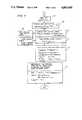
- FIGS. 6 and 7are flow charts illustrating programming of the digital processor of FIG. 5.
- FIG. 8is a schematic block diagram illustrating an alternate switch mode integrator embodiment.
- a typical incremental or digital servo positioning systemperforms moves of a mechanical element such as a robot arm from position A to position B along some prescribed path, as shown in FIG. 1. This path has some inherent velocity profile as shown in FIG. 2.
- the position and velocity profiles in FIGS. 1 and 2only illustrate one possible trajectory path.
- Most applications of such digital servo positioning systemsrequire very high position accuracy and holding stiffness at the end positions A and B where the velocity of the element is zero. High stiffness during pathtracking, i.e., when velocity of the element is nonzero, is also required to minimize the effect of external disturbances on system performance.
- a servo positioning systemwhich employs a switch mode integrator to generate a control signal U total for maintaining stiffness of a mechanical element both at the end positions A, B and during pathtracking is shown in FIG. 3.
- the system of FIG. 3includes a path generator 13, which generates path data comprising path position signals X k-n , the path position data for one-dimensional path motion.
- the path position signals X k-nindicate the desired position of a mechanical element or member included in the system plant 28.
- the path generator 13outputs the desired path position signals X k-1 , X k , X k+1 and X k over three output lines 14, 15, 16 to a computing element 17, a switch mode integrator 18, and a summer 19.
- the computing element 17applies a transfer function 1/G(Z) to the path data and outputs an open loop control voltage U openloop (k) on an output line 21.
- the switch mode integrator 18supplies an integrator control voltage U integrator (k) on an output line 22.
- the summer 19outputs an error signal E k on a line 23 to a computational element 25.
- the computational element 25applies a feedback control transfer function D(Z) on the input error signal E k and outputs a feedback control voltage U feedback (k) on an output line 27.
- the three output lines 21, 23, 27are connected to a summer 29 which adds the open loop, feedback and integrator control voltages U openloop (k), U feedback (k), U integrator (k) to produce a total output control voltage U total (k) on an output line 30.
- the output control voltage U total (k) on the output line 30is applied to the system plant 28, resulting in an actual path location of the mechanical element of the plant 28 represented by an actual position signal Y k .
- the transfer function of the actual plant 28is represented by G*(Z).
- the switch mode integrator 18includes a reference velocity translator 31 receiving the path location data X k-1 , X k , X k+1 . . . , and outputting commanded velocity data X k over a line 33 to a third summer 35.
- the subscript kindicates the value of the variable, e.g., X, during various time intervals or "iterations.”
- the subscripts (k-1) and (k+1)indicate the values of the variable during intervals immediately preceding and succeeding time interval k.
- the velocity error output V e (k), V e (k-1) of the third summer 35is supplied to switch control logic 43 over a line 45.
- the switch control logic 43receives a second input comprising the position error signals E k , E k-1 over a line 47 and supplies an integrator input error signal I e (k-1), I ek to a lead/lag integrator 49.
- the path generator 13supplies the reference positions, X k , equally spaced in time.
- this signal U feedback (k)is the only component of U total (k) and is sent out to the plant, G*(z) which may comprise, for example, an amplifier, a motor, and a load.
- the system in FIG. 3employs two additional components to determine U total (k).
- the first additional component, the open loop control signal, U openloop (k),is added to reduce the pathtracking errors inherent in feedback control systems.
- This open loop control signalis not essential to advantageous use of the switch mode integrator 18 of the preferred embodiment.
- the switch mode integrator control signal, U integrator (k),is added to supply stiffness during holding and pathtracking within the plant G*(z).
- the conditions for operation of the switch 43are:
- the reference velocity translator 31generates commanded velocities represented by velocity signals, X k , from position references, X k , while the actual velocity translator 39 calculates actual velocity signals, Y k , from actual positions, Y k .
- the switch mode integrator 18integrates velocity error, V ek , during pathtracking, and position error, E k , during holding.
- FIG. 4shows an example of an actual plant 101, with an input voltage U(Z) resulting in an output position X(Z).
- the digital transfer function of this plant 101is ##EQU1##
- the transfer function G*(Z)represents a plant including a voltage mode amplifier, motor, load and encoder, as illustrated, for example, in FIG. 5, to be described in further detail below.
- the open loop controlis preferably generated by solving a difference equation derived from the plant model G(z), which represents the dynamics of a DC motor, amplifier, lead screw, load and encoder.
- An equation of this formis called noncausal since the computation of the present control signal, U openloop (k), requires the knowledge of a future event, namely X k+1 .
- Noncausal equationsare not possible in feedback control since a future error, E k+1 is not known.
- the open loop calculationrequires the future target point, X k+1 along the path.
- the target positionsare precomputed using the well-known trapezoidal velocity profile and are thus available. If the target positions are not known in advance, then the target command could be delayed one sample period. Thus, the next target would be known one sample period before it is commanded.
- Equation (3)is implemented by computing element 17 in FIG. 3. Equation (3) may also be rewritten in terms of velocities V n as follows: ##EQU4##
- FIG. 5A hardware embodiment of the preferred embodiment is illustrated in FIG. 5.
- This embodimentincludes a path generator 13, a buffer 32, a digital control card 34, a voltage mode amplifier 42, a motor 46, and an encoder 44.
- the motor 46controls movement of a robotic element or member 48 such as a mechanical arm along a selected axis, as is well-known in the art.
- the digital control card or control section 34includes a digital filter 40 embodied in, for example, a Motorola 68000 microprocessor operating at 121/2 MHz.
- the digital filter 40may also be embodied in various forms of digital logic, other programmed processors, or special purpose signal processor circuitry.
- the digital filter 40performs the function of the filter 17, filter 25, velocity translators 31, 39, the switch 43, the integrator 49 and the first, second and third summing junctions 19, 29 and 35 of FIG. 1.
- the digital filter 40receives the path or trajectory information provided by the path generator 13 and stored in the buffer 32.
- the digital filter 40outputs the total control signal U total to the digital-to-analog converter 41.
- the digital-to-analog converter 41in turn provides an analog control signal to the amplifier 42 for controlling the motor 46.
- the encoder 44tracks the actual motor position and provides a feedback signal on line 24 to the digital filter 40.
- the DAC 41, amplifier 42, motor 46, encoder 44, and load 48comprise the plant 28 illustrated in FIG. 3 having the transfer function G*(Z).
- each additional card 36 . . . 38contains its own buffer 32.
- Each buffer 32receives path data for controlling motion on its particular dimension.
- the buffer 32 of card 34may receive X path data
- buffer 32 of card 36may receive Y path data
- the buffer 32 of card 38may receive Z path data.
- Other dimensionsinclude roll, pitch, yaw, etc., as known in the robotics art.
- a Pacific Scientific 2VM-6202-7 DC servo motorhas been used for the motor 46 and a Disk Instruments rotary optical encoder M-98A-1000-ICLP yielding 4,000 counts per revolution with quadrature has been used for encoder 44.
- the amplifier 42is a 40-volt, 12-amp Glentek GA45555 linear voltage mode amplifier.
- the digital-to-analog converter 41is a Burr-Brown AD667.
- FIGS. 6 and 7A flowchart for programming the Motorola 68000 microprocessor to perform the digital filtering functions of digital filter 40, including the function of the switch mode integrator 18, are illustrated in FIGS. 6 and 7. Performance of the routine starts at the beginning of every sample period with step 51. Execution of the filter algorithm continues sequentially with steps 57, 59, 61, etc. of FIGS. 6 and 7. The entire algorithm is computed within the sample period. The algorithm is performed autonomously by each digital filter 40 on each card 34, 36 . . . 38 for the respective dimension whose path data is supplied to that card through the associated buffer 32. In an embodiment employing additional cards 36 . . . 38, each additional card is synchronized to the same sample period.
- step 61the feedback control D(z) is computed. This term D(z) is computed by multiplying a constant A 1 times the error signal E k and adding to it a quantity denoted Prec 1, which is a precalculated quantity, as described hereafter.
- step 70After calculating the lead lag integrator function, the flow proceeds to step 70, where limits are set on the integrator in order to prevent it from growing unbounded in the event of hardware malfunctions such as amplifier shutdown. According to step 70, if the value of U integrator is greater than a limit I max or less than a limit I min , U integrator is set to the I.sub. max or I min value, respectively.
- step 63the next target, X k+1 is read from the buffer 32 into the processor 40.
- the open loop control parameteris calculated by multiplying a constant B 1 times X k+1 and adding to it a second precalculated value Prec 2 as described hereafter.
- the total control signal U total (k)is determined in accordance with the summing junction 29 in FIG. 1.
- step 69a limit test is performed on the total control signal U total .
- the signal, U totalis compared to parameters denoted DACMAX and DACMIN and clipped if necessary. These parameters are selected to limit the input voltage signal within a range matched to the amplifier 42.
- the control signal U totalis then sent to the DAC 41 and then to the amp 42 and motor 46 in step 71.
- the parameters determined during this servo updateare saved in step 73 for the next servo update 51.
- the routinethen proceeds to block 75, where all possible terms for the next iteration of servo update 51 are calculated to minimize the time between the beginning of the sample period, step 51, and the output of U total to the DAC/amp/motor, step 71.
- the two parameters previously referred to as Prec 1 and Prec 2are calculated according to the equations established.
- all history termsare initially set to zero.
- the sample periodis 1 millisecond and generates a high priority interrupt to the processor 40 so that the beginning of the digital servo algorithm is synchronized to the beginning of every sample period.
- the path generator 13can be run before starting the move or concurrently therewith.
- the path generator 13may read out previously-stored path information, or may be a computer which calculates detailed trajectory data for a target path in response to general position commands, as desired.
- V ekE k -E k-1 .
- a switch 103switches the error signal either to position "D," the input of a differentiator 105, or to position "U" connected to the input 45 of the integrator 49.
- the conditions governing switching by the switch 103are as follows:
- the system of FIG. 8does not show open loop control, which may or may not be added.
- the integrator 49may be viewed as having an input of position error during holding and the derivative of position error during pathtracking.
- the integrator 49tries to drive the position error to zero during holding while trying to keep the position error from changing (growing) during pathtracking.
- This combinationworks very well for reducing the sensitivity of the system to external disturbances.
- the implementation of the switch mode integrator 18 in FIG. 8is not used in the actual embodiment, since the commanded velocity is required for the other parts of the control logic for the system.
- U integrator (k)C 1 I ek -C 2 I e (k-1) +U integrator (k-1), may be noted.
- the new integrator valueis always some value which is dependent on the input plus the old integrator value.
- U integrator (k-1)helps smooth the integrator perturbations introduced by switching the input between position and velocity error.
Landscapes
- Engineering & Computer Science (AREA)
- Human Computer Interaction (AREA)
- Manufacturing & Machinery (AREA)
- Physics & Mathematics (AREA)
- General Physics & Mathematics (AREA)
- Automation & Control Theory (AREA)
- Control Of Position Or Direction (AREA)
- Feedback Control In General (AREA)
Abstract
Description
Claims (26)
U.sub.integrator(k) =C.sub.1 I.sub.e(k) -C.sub.2 I.sub.e(k-1)+U.sub.integrator(k-1)
Priority Applications (1)
| Application Number | Priority Date | Filing Date | Title |
|---|---|---|---|
| US07/271,477US4893068A (en) | 1988-11-15 | 1988-11-15 | Digital servo employing switch mode lead/lag integrator |
Applications Claiming Priority (1)
| Application Number | Priority Date | Filing Date | Title |
|---|---|---|---|
| US07/271,477US4893068A (en) | 1988-11-15 | 1988-11-15 | Digital servo employing switch mode lead/lag integrator |
Publications (1)
| Publication Number | Publication Date |
|---|---|
| US4893068Atrue US4893068A (en) | 1990-01-09 |
Family
ID=23035752
Family Applications (1)
| Application Number | Title | Priority Date | Filing Date |
|---|---|---|---|
| US07/271,477Expired - Fee RelatedUS4893068A (en) | 1988-11-15 | 1988-11-15 | Digital servo employing switch mode lead/lag integrator |
Country Status (1)
| Country | Link |
|---|---|
| US (1) | US4893068A (en) |
Cited By (22)
| Publication number | Priority date | Publication date | Assignee | Title |
|---|---|---|---|---|
| US5097744A (en)* | 1991-01-14 | 1992-03-24 | General Electric Company | Hydraulic control system |
| US5159250A (en)* | 1991-01-26 | 1992-10-27 | Samsung Electronics Co., Ltd. | Robot control method |
| US5180956A (en)* | 1990-03-30 | 1993-01-19 | Kabushiki Kaisha Toshiba | Adaptability controller for robots |
| WO1993019408A1 (en)* | 1992-03-24 | 1993-09-30 | Art Tech Gigadisc 'atg' | Control device for maintaining an object in a given position |
| US5384526A (en)* | 1993-07-13 | 1995-01-24 | Wangdat, Inc. | PI or PID control loop with self-limiting integrator |
| US5517099A (en)* | 1993-06-15 | 1996-05-14 | International Modern Technologies, Inc. | Method and apparatus for robust integral-pulse control of a servodrive of unknown dynamics |
| AU684421B2 (en)* | 1995-06-20 | 1997-12-11 | Kabushiki Kaisha Toshiba | Digital PID control apparatus |
| US6013995A (en)* | 1996-09-02 | 2000-01-11 | Samsung Electronics Co., Ltd. | Method and apparatus for adaptive feedforward control with reduced noise during track seek operations |
| WO2002025640A2 (en) | 2000-09-21 | 2002-03-28 | Gsi Lumonics Corporation | Digital control servo system |
| EP0881044A4 (en)* | 1995-09-11 | 2002-05-02 | Yaskawa Denki Seisakusho Kk | ROBOT CONTROL CIRCUIT |
| US20040108828A1 (en)* | 2002-07-06 | 2004-06-10 | Samsung Electronics Co | Method and apparatus for controlling DC motor |
| US20050088132A1 (en)* | 2003-10-28 | 2005-04-28 | Curtis Steven E. | Methods and systems for reducing unintentional collisions |
| US20050162174A1 (en)* | 2004-01-23 | 2005-07-28 | Yuhong Huang | System and method for adjusting a pid controller in a limited rotation motor system |
| US20060113375A1 (en)* | 2003-06-16 | 2006-06-01 | Caiger Simon G | Monitoring and controlling of laser operation |
| US20080084171A1 (en)* | 2006-10-06 | 2008-04-10 | Jonathan Robert Leehey | Method and apparatus for controlling motors of different types |
| US20080303474A1 (en)* | 2007-06-08 | 2008-12-11 | Gsi Group Corporation | Systems and methods for controlling limited rotation motor systems |
| US20100152868A1 (en)* | 2008-12-17 | 2010-06-17 | Industrial Technology Research Institute | Motion control servo loop apparatus |
| CN109240092A (en)* | 2018-11-30 | 2019-01-18 | 长春工业大学 | Based on multiple agent reconfigurable modular flexible mechanical arm Trajectory Tracking Control method |
| US10333435B2 (en) | 2017-02-22 | 2019-06-25 | Performance Motion Devices, Inc. | Multi-motor controller |
| US10481598B2 (en) | 2017-09-22 | 2019-11-19 | Performance Motion Devices, Inc. | Motion system with sensor outputs and haptic controls |
| CN113987914A (en)* | 2021-09-23 | 2022-01-28 | 北京电子工程总体研究所 | Space robot tracking control method facing cold air propulsion |
| WO2023148326A1 (en)* | 2022-02-04 | 2023-08-10 | Asml Netherlands B.V. | Lithographic apparatus controller system |
Citations (5)
| Publication number | Priority date | Publication date | Assignee | Title |
|---|---|---|---|---|
| US3633086A (en)* | 1969-02-12 | 1972-01-04 | Siemens Ag | Closed-loop regulating system for a control circuit with a control drive |
| US4713596A (en)* | 1985-07-10 | 1987-12-15 | General Electric Company | Induction motor drive system |
| US4754208A (en)* | 1986-11-17 | 1988-06-28 | Nippon Kokan Kabushiki Kaisha | Circular path control apparatus and method for multi-axis servomechanisms |
| US4816734A (en)* | 1985-11-27 | 1989-03-28 | Fanuc Ltd | Speed control system |
| US4843293A (en)* | 1987-02-02 | 1989-06-27 | Research Development Corporation | Apparatus for controlling servo system employing piezo-electric actuator |
- 1988
- 1988-11-15USUS07/271,477patent/US4893068A/ennot_activeExpired - Fee Related
Patent Citations (5)
| Publication number | Priority date | Publication date | Assignee | Title |
|---|---|---|---|---|
| US3633086A (en)* | 1969-02-12 | 1972-01-04 | Siemens Ag | Closed-loop regulating system for a control circuit with a control drive |
| US4713596A (en)* | 1985-07-10 | 1987-12-15 | General Electric Company | Induction motor drive system |
| US4816734A (en)* | 1985-11-27 | 1989-03-28 | Fanuc Ltd | Speed control system |
| US4754208A (en)* | 1986-11-17 | 1988-06-28 | Nippon Kokan Kabushiki Kaisha | Circular path control apparatus and method for multi-axis servomechanisms |
| US4843293A (en)* | 1987-02-02 | 1989-06-27 | Research Development Corporation | Apparatus for controlling servo system employing piezo-electric actuator |
Cited By (43)
| Publication number | Priority date | Publication date | Assignee | Title |
|---|---|---|---|---|
| US5180956A (en)* | 1990-03-30 | 1993-01-19 | Kabushiki Kaisha Toshiba | Adaptability controller for robots |
| FR2671584A1 (en)* | 1991-01-14 | 1992-07-17 | Gen Electric | HYDRAULIC CONTROL DEVICE. |
| US5097744A (en)* | 1991-01-14 | 1992-03-24 | General Electric Company | Hydraulic control system |
| US5159250A (en)* | 1991-01-26 | 1992-10-27 | Samsung Electronics Co., Ltd. | Robot control method |
| WO1993019408A1 (en)* | 1992-03-24 | 1993-09-30 | Art Tech Gigadisc 'atg' | Control device for maintaining an object in a given position |
| FR2689261A1 (en)* | 1992-03-24 | 1993-10-01 | Atg Sa | Control device for controlling an object at a given position. |
| US5455495A (en)* | 1992-03-24 | 1995-10-03 | Art Tech Gigadisc "Atg" | Control device for servocontrolling an object to a given position |
| US5517099A (en)* | 1993-06-15 | 1996-05-14 | International Modern Technologies, Inc. | Method and apparatus for robust integral-pulse control of a servodrive of unknown dynamics |
| US5384526A (en)* | 1993-07-13 | 1995-01-24 | Wangdat, Inc. | PI or PID control loop with self-limiting integrator |
| AU684421B2 (en)* | 1995-06-20 | 1997-12-11 | Kabushiki Kaisha Toshiba | Digital PID control apparatus |
| EP0881044A4 (en)* | 1995-09-11 | 2002-05-02 | Yaskawa Denki Seisakusho Kk | ROBOT CONTROL CIRCUIT |
| US6013995A (en)* | 1996-09-02 | 2000-01-11 | Samsung Electronics Co., Ltd. | Method and apparatus for adaptive feedforward control with reduced noise during track seek operations |
| US20020049513A1 (en)* | 2000-09-21 | 2002-04-25 | Nussbaum Michael B. | Digital control servo system |
| WO2002025640A2 (en) | 2000-09-21 | 2002-03-28 | Gsi Lumonics Corporation | Digital control servo system |
| US7421308B2 (en) | 2000-09-21 | 2008-09-02 | Gsi Group Corporation | Digital control servo system |
| US20070239290A1 (en)* | 2000-09-21 | 2007-10-11 | Gsi Group Corporation | Digital control servo system |
| US7200464B2 (en) | 2000-09-21 | 2007-04-03 | Gsi Group Corporation | Digital control servo system |
| US20040108828A1 (en)* | 2002-07-06 | 2004-06-10 | Samsung Electronics Co | Method and apparatus for controlling DC motor |
| US6831438B2 (en)* | 2002-07-06 | 2004-12-14 | Samsung Electronics Co., Ltd. | Method and apparatus for controlling DC motor |
| US7331512B2 (en) | 2003-06-16 | 2008-02-19 | Gsi Group Corporation | Monitoring and controlling of laser operation |
| US20060113375A1 (en)* | 2003-06-16 | 2006-06-01 | Caiger Simon G | Monitoring and controlling of laser operation |
| US7034492B2 (en)* | 2003-10-28 | 2006-04-25 | Ge Medical Systems Global Technology Company, Llc | Methods and systems for reducing unintentional collisions |
| US20060087274A1 (en)* | 2003-10-28 | 2006-04-27 | Ge Medical Systems Global Technology Company, Llc | Methods and systems for reducing unintentional collisions |
| US20050088132A1 (en)* | 2003-10-28 | 2005-04-28 | Curtis Steven E. | Methods and systems for reducing unintentional collisions |
| US7368888B2 (en) | 2003-10-28 | 2008-05-06 | Ge Medical Systems Global Technology Company, Llc | Methods and systems for reducing unintentional collisions |
| US20050177330A1 (en)* | 2004-01-23 | 2005-08-11 | Yuhong Huang | System and method for optimizing character marking performance |
| US7170251B2 (en) | 2004-01-23 | 2007-01-30 | Gsi Group Corporation | System and method for diagnosing a controller in a limited rotation motor system |
| US20050174124A1 (en)* | 2004-01-23 | 2005-08-11 | Yuhong Huang | System and method for diagnosing a controller in a limited rotation motor system |
| US7291999B2 (en) | 2004-01-23 | 2007-11-06 | Gsi Group Corporation | System and method for diagnosing a controller in a limited rotation motor system |
| US20050162174A1 (en)* | 2004-01-23 | 2005-07-28 | Yuhong Huang | System and method for adjusting a pid controller in a limited rotation motor system |
| US20070121485A1 (en)* | 2004-01-23 | 2007-05-31 | Gsi Group Corporation | System and method for adjusting a pid controller in a limited rotation motor system |
| US7190144B2 (en) | 2004-01-23 | 2007-03-13 | Gsi Group Corporation | System and method for adjusting a PID controller in a limited rotation motor system |
| US7719214B2 (en) | 2006-10-06 | 2010-05-18 | Performance Motion Devices, Inc. | Method and apparatus for controlling motors of different types |
| US20080084171A1 (en)* | 2006-10-06 | 2008-04-10 | Jonathan Robert Leehey | Method and apparatus for controlling motors of different types |
| US20080303474A1 (en)* | 2007-06-08 | 2008-12-11 | Gsi Group Corporation | Systems and methods for controlling limited rotation motor systems |
| US20100152868A1 (en)* | 2008-12-17 | 2010-06-17 | Industrial Technology Research Institute | Motion control servo loop apparatus |
| US8090455B2 (en)* | 2008-12-17 | 2012-01-03 | Industrial Technology Research Institute | Motion control servo loop apparatus |
| US10333435B2 (en) | 2017-02-22 | 2019-06-25 | Performance Motion Devices, Inc. | Multi-motor controller |
| US10481598B2 (en) | 2017-09-22 | 2019-11-19 | Performance Motion Devices, Inc. | Motion system with sensor outputs and haptic controls |
| CN109240092A (en)* | 2018-11-30 | 2019-01-18 | 长春工业大学 | Based on multiple agent reconfigurable modular flexible mechanical arm Trajectory Tracking Control method |
| CN113987914A (en)* | 2021-09-23 | 2022-01-28 | 北京电子工程总体研究所 | Space robot tracking control method facing cold air propulsion |
| CN113987914B (en)* | 2021-09-23 | 2024-05-03 | 北京电子工程总体研究所 | Space robot tracking control method for cold air propulsion |
| WO2023148326A1 (en)* | 2022-02-04 | 2023-08-10 | Asml Netherlands B.V. | Lithographic apparatus controller system |
Similar Documents
| Publication | Publication Date | Title |
|---|---|---|
| US4893068A (en) | Digital servo employing switch mode lead/lag integrator | |
| US4912753A (en) | Robot axis controller employing feedback and open loop (feedforward) control | |
| US5404253A (en) | Estimator-based runout compensation in a disk drive | |
| US5107193A (en) | Feedforward control apparatus for a servomotor | |
| US5015934A (en) | Apparatus and method for minimizing limit cycle using complementary filtering techniques | |
| US5684374A (en) | Method and apparatus for tuning a motion control system having an external velocity loop | |
| Torfs et al. | Comparison of two feedforward design methods aiming at accurate trajectory tracking of the end point of a flexible robot arm | |
| US5373221A (en) | Method and system for estimating robot tool center point speed | |
| US4041287A (en) | Final servo control in NC systems | |
| US5726878A (en) | Prediction controller | |
| US4214192A (en) | Path control apparatus for the computer directed control of a numerically controlled machine tool | |
| US4553078A (en) | Servo control booster system for minimizing following error | |
| JPH0795243B2 (en) | Power servo device | |
| US4797835A (en) | Model follower control apparatus | |
| Ciliz et al. | Adaptive control of robotic manipulators using multiple models and switching | |
| JP3062606B2 (en) | Adaptive controller using neural network | |
| US4578763A (en) | Sampled data servo control system with deadband compensation | |
| US4577271A (en) | Sampled data servo control system | |
| US5561568A (en) | Method and apparatus for fast positioning a head of a recording device | |
| US6163730A (en) | Method and control system for changing the state of a plant | |
| US5805374A (en) | Method and apparatus for fast positioning a head of a recording device | |
| KR100450084B1 (en) | System controller whose robustness and functional performance are improved | |
| KR970003877B1 (en) | Feed Forward Control Method of Servo Motor | |
| US6968258B2 (en) | Residual feedback to improve estimator prediction | |
| JP2594423B2 (en) | Industrial robot controller |
Legal Events
| Date | Code | Title | Description |
|---|---|---|---|
| AS | Assignment | Owner name:HUGHES AIRCRAFT COMPANY, LOS ANGELES, CALIFORNIA, Free format text:ASSIGNMENT OF ASSIGNORS INTEREST.;ASSIGNOR:EVANS, DANIEL D. JR.;REEL/FRAME:004987/0599 Effective date:19881109 Owner name:HUGHES AIRCRAFT COMPANY, A DE CORP., CALIFORNIA Free format text:ASSIGNMENT OF ASSIGNORS INTEREST;ASSIGNOR:EVANS, DANIEL D. JR.;REEL/FRAME:004987/0599 Effective date:19881109 | |
| FPAY | Fee payment | Year of fee payment:4 | |
| AS | Assignment | Owner name:PALOMAR TECHNOLOGIES CORPORATION, CALIFORNIA Free format text:ASSIGNMENT OF ASSIGNORS INTEREST;ASSIGNOR:HUGHES AIRCRAFT COMPANY;REEL/FRAME:007715/0955 Effective date:19951006 | |
| FEPP | Fee payment procedure | Free format text:PAT HOLDER CLAIMS SMALL ENTITY STATUS - SMALL BUSINESS (ORIGINAL EVENT CODE: SM02); ENTITY STATUS OF PATENT OWNER: SMALL ENTITY | |
| AS | Assignment | Owner name:CHEMICAL BANK, AS AGENT, NEW YORK Free format text:ASSIGNMENT FOR SECURITY;ASSIGNOR:PALOMAR TECHNOLOGIES CORPORATION;REEL/FRAME:007603/0481 Effective date:19951006 | |
| FPAY | Fee payment | Year of fee payment:8 | |
| AS | Assignment | Owner name:PALOMAR TECHNOLOGIES, INC., CALIFORNIA Free format text:ASSIGNMENT OF ASSIGNORS INTEREST;ASSIGNOR:PALOMAR TECHNOLOGIES CORPORATION;REEL/FRAME:011425/0755 Effective date:20001218 | |
| REMI | Maintenance fee reminder mailed | ||
| LAPS | Lapse for failure to pay maintenance fees | ||
| STCH | Information on status: patent discontinuation | Free format text:PATENT EXPIRED DUE TO NONPAYMENT OF MAINTENANCE FEES UNDER 37 CFR 1.362 | |
| FP | Lapsed due to failure to pay maintenance fee | Effective date:20020109 |