US4893039A - Windshield wiper motor - Google Patents
Windshield wiper motorDownload PDFInfo
- Publication number
- US4893039A US4893039AUS07/204,806US20480688AUS4893039AUS 4893039 AUS4893039 AUS 4893039AUS 20480688 AUS20480688 AUS 20480688AUS 4893039 AUS4893039 AUS 4893039A
- Authority
- US
- United States
- Prior art keywords
- motor
- gear
- windshield wiper
- hole
- passage
- Prior art date
- Legal status (The legal status is an assumption and is not a legal conclusion. Google has not performed a legal analysis and makes no representation as to the accuracy of the status listed.)
- Expired - Lifetime
Links
- 230000029058respiratory gaseous exchangeEffects0.000abstractdescription10
- 239000010687lubricating oilSubstances0.000abstractdescription7
- 239000003921oilSubstances0.000abstract1
- 230000035515penetrationEffects0.000description3
- 238000010276constructionMethods0.000description1
- 230000000694effectsEffects0.000description1
- 239000011521glassSubstances0.000description1
- 230000020169heat generationEffects0.000description1
- XLYOFNOQVPJJNP-UHFFFAOYSA-NwaterSubstancesOXLYOFNOQVPJJNP-UHFFFAOYSA-N0.000description1
Images


Classifications
- F—MECHANICAL ENGINEERING; LIGHTING; HEATING; WEAPONS; BLASTING
- F16—ENGINEERING ELEMENTS AND UNITS; GENERAL MEASURES FOR PRODUCING AND MAINTAINING EFFECTIVE FUNCTIONING OF MACHINES OR INSTALLATIONS; THERMAL INSULATION IN GENERAL
- F16H—GEARING
- F16H57/00—General details of gearing
- F16H57/02—Gearboxes; Mounting gearing therein
- F16H57/027—Gearboxes; Mounting gearing therein characterised by means for venting gearboxes, e.g. air breathers
- B—PERFORMING OPERATIONS; TRANSPORTING
- B60—VEHICLES IN GENERAL
- B60S—SERVICING, CLEANING, REPAIRING, SUPPORTING, LIFTING, OR MANOEUVRING OF VEHICLES, NOT OTHERWISE PROVIDED FOR
- B60S1/00—Cleaning of vehicles
- B60S1/02—Cleaning windscreens, windows or optical devices
- B60S1/04—Wipers or the like, e.g. scrapers
- B60S1/06—Wipers or the like, e.g. scrapers characterised by the drive
- B60S1/16—Means for transmitting drive
- H—ELECTRICITY
- H02—GENERATION; CONVERSION OR DISTRIBUTION OF ELECTRIC POWER
- H02K—DYNAMO-ELECTRIC MACHINES
- H02K5/00—Casings; Enclosures; Supports
- H02K5/04—Casings or enclosures characterised by the shape, form or construction thereof
- H02K5/10—Casings or enclosures characterised by the shape, form or construction thereof with arrangements for protection from ingress, e.g. water or fingers
- H—ELECTRICITY
- H02—GENERATION; CONVERSION OR DISTRIBUTION OF ELECTRIC POWER
- H02K—DYNAMO-ELECTRIC MACHINES
- H02K2205/00—Specific aspects not provided for in the other groups of this subclass relating to casings, enclosures, supports
- H02K2205/09—Machines characterised by drain passages or by venting, breathing or pressure compensating means
- H—ELECTRICITY
- H02—GENERATION; CONVERSION OR DISTRIBUTION OF ELECTRIC POWER
- H02K—DYNAMO-ELECTRIC MACHINES
- H02K7/00—Arrangements for handling mechanical energy structurally associated with dynamo-electric machines, e.g. structural association with mechanical driving motors or auxiliary dynamo-electric machines
- H02K7/10—Structural association with clutches, brakes, gears, pulleys or mechanical starters
- H02K7/116—Structural association with clutches, brakes, gears, pulleys or mechanical starters with gears
- H02K7/1163—Structural association with clutches, brakes, gears, pulleys or mechanical starters with gears where at least two gears have non-parallel axes without having orbital motion
- H02K7/1166—Structural association with clutches, brakes, gears, pulleys or mechanical starters with gears where at least two gears have non-parallel axes without having orbital motion comprising worm and worm-wheel
Definitions
- This inventionrelates to a windshield wiper motor used for an electric windshield wiper assembly which wipes off raindrops and the like for example from windshield glass of an automobile with the wiper blade so as not disturb the driving view, and in particular to a windshield wiper motor having a breathing structure possible to breathe smoothly between the inside and outside thereof.
- numeral 101is a motor part housing a rotor 102 possible to rotate in a normal and reverse direction in a motor case 103 with an opening at the end.
- Numeral 104is a gear part, outside gear parts 106a and 107a of intermediate gears 106 and 107 are engaged with a worm part 102a of rotor 102 extended from said motor part 101 to the inside of a gear case 105 through a piercing hole 105a provided at an end of the gear case 105, and an output gear wheel 108 is engaged with pinion parts 106b and 107b of said intermediate gears 106 and 107, an output shaft 109 fixed to the output gear wheel 108 is made into an output and extending to the outside of the gear case 105.
- the motor part 101 and the gear part 104are connected at respective ends of the motor case 103 and the gear case 105, and a through hole 105b communicating with the inside of the gear case 105 and the inside of the motor part 101 at the end of the gear case 105 on the motor part 101 side makes the gear part 104 and the motor part 101 into the communicating state as shown in FIG. 7.
- Numeral 110is a breather, disposed in an air hole 105d pierced through in a part of a bottom plate 105c of the gear case 105 and connecting the upper and lower sides of the bottom plate 105c in FIG. 6, in the downwardly pressed state as shown in FIG. 6.
- the breather 110is provided with a shell shaped part 110a at the lower side thereof in FIG. 6, a breather hole 111 is formed which communicates crookedly with the inside and the outside of the gear case 105 through the shell shaped part 110a. So that, the penetration of water or the like into the inside of the gear case 105 or motor case 103 owing to the breathing action caused by generation of heat accompanying the working and stopping of the windshield wiper motor is prevented.
- lubricating oil applied on gears in the gear case 105sometimes penetrates into the through hole 105b provided in the gear case 105. There is a problem that the breathing action becomes impossible in the case the through hole 105b is closed with said lubricating oil. Also in the breather 110 provided in the bottom plate 105c of the gear case 105, lubricating oil applied on gears in the gear case 105 sometimes penetrates into the breather hole 111, there is a problem that the breathing action becomes impossible similar to the case of through hole 105b.
- this inventionis considered in order to solve the aforementioned problems and is made as a result of particular considerations on the structure with object of providing a windshield wiper motor equipped with a breather hole without the penetration of lubricating oil applied on gears in the gear case and capable to make smooth breathing action continuously.
- the windshield wiper motor according to this inventionhas structural features that in a windshield wiper motor equipped with a breather hole making the inside of a gear case housing a gear part and the inside of a motor case housing a motor part communicate with the outside thereof, a crooked air passage communicating with an opening in said gear part side and an opening in said motor part side in provided between said gear and motor part, and said air passage in provided with said breather hole at a position that neither concides nor overlaps with projection of said opening in the gear part side or projection of said opening in the motor part side in the opening direction.
- FIG. 1is a side view partly in section of an embodiment of the windshield wiper motor according to this invention
- FIG. 2is a top view partly in section of the windshield wiper motor shown in FIG. 1;
- FIG. 3is a bottom view of the windshield wiper motor shown in FIG. 1;
- FIG. 4is a vertical sectional view of the neighborhood of breather hole in the windshield wiper motor shown in FIG. 1;
- FIG. 5is a perspective outside view partly in section of the breather in windshield wiper motor according to this invention.
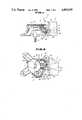
- FIG. 6is a side view partly in section of applicant's previous windshield wiper motor.
- FIG. 7is a top view partly in section of the windshield wiper motor shown in FIG. 6.
- numeral 2is a motor part.
- a rotor 4(refer to FIG. 2) rotatable in a normal and reverse direction is housed in a motor case 3 provided with an opening at the end, and an end portion of the rotor 4 is extended from the opening at the end of the motor case 3, and a worm part 4a is formed at the extended end portion.
- Numeral 5is a gear part.
- a gear case 6made up of flat bottomed and roughly triangular vessel and an end-bracket 7 for connecting with said motor case 3 at the right side portion in FIG. 1 are formed in a body, and the worm part 4a of the rotor 4 equipped in said motor part 2 is extended to the inside of the gear case 6 through a piercing hole 5c pierced in the end-bracket 7 in the horizontal direction in FIG. 2.
- Each of outside gear parts 8a and 9a of intermediate gears 8 and 9is engaged with said worm part 4a, then the rotation of the rotor 4 is transfered and reduced by means of engaging an output gear 10 with respective pinions 8b and 9b of said intermediate gears 8 and 9.
- the output gear 10is fixed to an output shaft 11, an end portion of the output shaft 11 is made into the output extending to the outside of the gear case 6.
- the end-bracket 7 of the gear part 5is provided with an air passage 12, which communicates crookedly with the inside of the gear case 6 and the motor case 3.
- a cylindrical shaped opening 12a of the gear part sideis provided which communicates with the inside of the gear case 6 protruding upward a little from said bottom plate 6a in FIG. 1, and maintaining a small gap between outside gear part 8a of the intermediate gear 8 and itself.
- the end-bracket 7is provided with an opening 12b on the motor part side communicating with the inside of the motor case 3 at the right side thereof in FIG. 1, and the crooked air passage 12 is equipped, which communicates with said opening 12a in the gear part side and the opening 12b in the motor part side within angle of approximately 90° in this embodiment.
- an air hole 12cis equipped in the position that neither coincides nor overlaps with either a projection of the opening 12a in said gear part side in the opening direction or a projection of the opening 12b in said motor part side in the opening direction, namely in this embodiment, in the position near to the opening 12b in the motor part 2 side offset from the crooked part of said air passage 12 in FIG. 1.
- numeral 13is a breather disposed in the air hole 12c, as shown in FIGS. 5 and 6.
- a vertical long leg 13ais provided with a hooking projection 13b at the upper end part, and with a shell shaped part 13c covering the circumference of said leg 13a for nearly half the length of it at the lower end part thereof.
- said leg 13ais provided with notching grooves 13d and 13d cutting off opposite side wall portions from the upper end part to the lower end part there of in the longitudinal direction.
- the breather 13is attached to the gear case 6 by pushing the hooking projection 13b of the breather 13 from the lower side of the air hole 12c of the air passage 12 in the figure, and forms a breather hole 14 communicating with the outside, between notching groove 13d of the leg 13a and air hole 12c.
- the windshield wiper motor according to this inventionhas structure that in a windshield wiper motor equipped with a breather hole making the inside of a gear case housing a gear part and the inside of a motor case housing a motor part communicate with the outside thereof, a crooked air passage communicating with an opening in said gear part side and an opening in said motor part side is provided between said gear and motor part, and said air passage is provided with said breather hole at a position that neither concides nor overlaps with projection of said opening in the gear part side or projection of said opening in the motor part side in the opening direction. Therefore, an excellent effect is obtained that the breathing action can be performed smoothly because the penetration of lubricating oil becomes extremely rare as compared with conventional windshield wiper motor and it is rare to interfere with the breathing action of the windshield wiper motor.
Landscapes
- Engineering & Computer Science (AREA)
- General Engineering & Computer Science (AREA)
- Mechanical Engineering (AREA)
- Power Engineering (AREA)
- Motor Or Generator Frames (AREA)
- General Details Of Gearings (AREA)
- Connection Of Motors, Electrical Generators, Mechanical Devices, And The Like (AREA)
Abstract
Description
1. Field of the Invention
This invention relates to a windshield wiper motor used for an electric windshield wiper assembly which wipes off raindrops and the like for example from windshield glass of an automobile with the wiper blade so as not disturb the driving view, and in particular to a windshield wiper motor having a breathing structure possible to breathe smoothly between the inside and outside thereof.
2. Description of Applicant's Unpublished Earlier Construction
Heretofore, there ha been such a windshield wiper motor as shown in FIGS. 6 and 7 for example.
Namely, in awindshield wiper motor 100 shown in the figures,numeral 101 is a motor part housing arotor 102 possible to rotate in a normal and reverse direction in amotor case 103 with an opening at the end. Numeral 104 is a gear part, outside gear parts 106a and 107a ofintermediate gears rotor 102 extended from saidmotor part 101 to the inside of agear case 105 through a piercing hole 105a provided at an end of thegear case 105, and anoutput gear wheel 108 is engaged withpinion parts intermediate gears output shaft 109 fixed to theoutput gear wheel 108 is made into an output and extending to the outside of thegear case 105.
Themotor part 101 and thegear part 104 are connected at respective ends of themotor case 103 and thegear case 105, and a throughhole 105b communicating with the inside of thegear case 105 and the inside of themotor part 101 at the end of thegear case 105 on themotor part 101 side makes thegear part 104 and themotor part 101 into the communicating state as shown in FIG. 7.
Numeral 110 is a breather, disposed in anair hole 105d pierced through in a part of abottom plate 105c of thegear case 105 and connecting the upper and lower sides of thebottom plate 105c in FIG. 6, in the downwardly pressed state as shown in FIG. 6. Thebreather 110 is provided with a shell shaped part 110a at the lower side thereof in FIG. 6, abreather hole 111 is formed which communicates crookedly with the inside and the outside of thegear case 105 through the shell shaped part 110a. So that, the penetration of water or the like into the inside of thegear case 105 ormotor case 103 owing to the breathing action caused by generation of heat accompanying the working and stopping of the windshield wiper motor is prevented.
However, in thewindshield wiper motor 100 as described above, for example on occasion of air inhalation in the breathing action caused by heat generation, lubricating oil applied on gears in thegear case 105 sometimes penetrates into thethrough hole 105b provided in thegear case 105. There is a problem that the breathing action becomes impossible in the case the throughhole 105b is closed with said lubricating oil. Also in thebreather 110 provided in thebottom plate 105c of thegear case 105, lubricating oil applied on gears in thegear case 105 sometimes penetrates into thebreather hole 111, there is a problem that the breathing action becomes impossible similar to the case of throughhole 105b.
Therefore, this invention is considered in order to solve the aforementioned problems and is made as a result of particular considerations on the structure with object of providing a windshield wiper motor equipped with a breather hole without the penetration of lubricating oil applied on gears in the gear case and capable to make smooth breathing action continuously.
In order to accomplish the aforementioned object, the windshield wiper motor according to this invention has structural features that in a windshield wiper motor equipped with a breather hole making the inside of a gear case housing a gear part and the inside of a motor case housing a motor part communicate with the outside thereof, a crooked air passage communicating with an opening in said gear part side and an opening in said motor part side in provided between said gear and motor part, and said air passage in provided with said breather hole at a position that neither concides nor overlaps with projection of said opening in the gear part side or projection of said opening in the motor part side in the opening direction.
FIG. 1 is a side view partly in section of an embodiment of the windshield wiper motor according to this invention;
FIG. 2 is a top view partly in section of the windshield wiper motor shown in FIG. 1;
FIG. 3 is a bottom view of the windshield wiper motor shown in FIG. 1;
FIG. 4 is a vertical sectional view of the neighborhood of breather hole in the windshield wiper motor shown in FIG. 1;
FIG. 5 is a perspective outside view partly in section of the breather in windshield wiper motor according to this invention;
FIG. 6 is a side view partly in section of applicant's previous windshield wiper motor; and
FIG. 7 is a top view partly in section of the windshield wiper motor shown in FIG. 6.
An embodiment of the windshield wiper motor according to this invention will be described below on basis of FIG. 1 to FIG. 5.
Namely, in a windshield wiper motor 1 showing in figures,numeral 2 is a motor part. A rotor 4 (refer to FIG. 2) rotatable in a normal and reverse direction is housed in amotor case 3 provided with an opening at the end, and an end portion of therotor 4 is extended from the opening at the end of themotor case 3, and a worm part 4a is formed at the extended end portion.
Numeral 5 is a gear part. Agear case 6 made up of flat bottomed and roughly triangular vessel and an end-bracket 7 for connecting with saidmotor case 3 at the right side portion in FIG. 1 are formed in a body, and the worm part 4a of therotor 4 equipped in saidmotor part 2 is extended to the inside of thegear case 6 through apiercing hole 5c pierced in the end-bracket 7 in the horizontal direction in FIG. 2. Each of outside gear parts 8a and 9a ofintermediate gears rotor 4 is transfered and reduced by means of engaging anoutput gear 10 withrespective pinions 8b and 9b of saidintermediate gears output gear 10 is fixed to an output shaft 11, an end portion of the output shaft 11 is made into the output extending to the outside of thegear case 6.
Hereupon, in this embodiment, the end-bracket 7 of thegear part 5 is provided with anair passage 12, which communicates crookedly with the inside of thegear case 6 and themotor case 3.
Namely, on a part of thebottom plate 6 of thegear case 6, under theintermediate gear 8 in FIG. 1 in this embodiment, a cylindrical shaped opening 12a of the gear part side is provided which communicates with the inside of thegear case 6 protruding upward a little from said bottom plate 6a in FIG. 1, and maintaining a small gap between outside gear part 8a of theintermediate gear 8 and itself.
The end-bracket 7 is provided with an opening 12b on the motor part side communicating with the inside of themotor case 3 at the right side thereof in FIG. 1, and thecrooked air passage 12 is equipped, which communicates with said opening 12a in the gear part side and the opening 12b in the motor part side within angle of approximately 90° in this embodiment.
And, anair hole 12c is equipped in the position that neither coincides nor overlaps with either a projection of the opening 12a in said gear part side in the opening direction or a projection of the opening 12b in said motor part side in the opening direction, namely in this embodiment, in the position near to the opening 12b in themotor part 2 side offset from the crooked part of saidair passage 12 in FIG. 1.
Hereupon,numeral 13 is a breather disposed in theair hole 12c, as shown in FIGS. 5 and 6. A vertical long leg 13a is provided with ahooking projection 13b at the upper end part, and with a shell shapedpart 13c covering the circumference of said leg 13a for nearly half the length of it at the lower end part thereof. And said leg 13a is provided withnotching grooves
In brief, as showing in FIG. 4, thebreather 13 is attached to thegear case 6 by pushing thehooking projection 13b of thebreather 13 from the lower side of theair hole 12c of theair passage 12 in the figure, and forms abreather hole 14 communicating with the outside, betweennotching groove 13d of the leg 13a andair hole 12c.
Thus the inside of thegear case 6 and the inside of themotor case 3 are made into communicating state with each other by theair passage 12, and are made into communicating state with the outside by thebreather hole 14.
Consequently, for example, even if lubricating oil applied to the gear parts provided in thegear case 6 penetrates into theair passage 12 through the opening 12a in the gear part side, theair passage 12 and thebreather hole 14 are never closed so easily and the breathing action becomes possible to be performed smoothly, because said opening 12a in the gear part side neither concides nor overlaps with projection of thebreather hole 14 or the opening 12b in the motor part side in the opening direction respectively.
As mentioned above, the windshield wiper motor according to this invention has structure that in a windshield wiper motor equipped with a breather hole making the inside of a gear case housing a gear part and the inside of a motor case housing a motor part communicate with the outside thereof, a crooked air passage communicating with an opening in said gear part side and an opening in said motor part side is provided between said gear and motor part, and said air passage is provided with said breather hole at a position that neither concides nor overlaps with projection of said opening in the gear part side or projection of said opening in the motor part side in the opening direction. Therefore, an excellent effect is obtained that the breathing action can be performed smoothly because the penetration of lubricating oil becomes extremely rare as compared with conventional windshield wiper motor and it is rare to interfere with the breathing action of the windshield wiper motor.
Claims (2)
1. A windshield wiper motor assembly comprising a motor casing having motor means therein,
a gear casing connected to said motor casing and having reduction gear means therein operatively connected to said motor means,
a crooked air passage extending between said motor casing and said gear casing with an opening at each end thereof in communication with each casing and
breather means located in said passage to provide communication between said passage and the atmosphere outside of said casings, wherein said breather means is provided with a hole offset from said openings at opposite ends of said passage in a position preventing straight line communication between said openings and said hole and includes a substantially T-shaped member having a leg portion and a cap portion with said leg portion disposed in said hole and having at least one groove extending along the length thereof.
2. A windshield wiper motor assembly as set forth in claim 1, wherein said air passage has a substantially L-shaped configuration and said hole of said breather means has an axis intersecting and perpendicular to one leg of said L-shaped passage and offset and parallel to another leg of said L-shaped passage.
Applications Claiming Priority (2)
| Application Number | Priority Date | Filing Date | Title |
|---|---|---|---|
| JP1987089606UJPH056215Y2 (en) | 1987-06-12 | 1987-06-12 | |
| JP62-89606[U] | 1987-06-12 |
Publications (1)
| Publication Number | Publication Date |
|---|---|
| US4893039Atrue US4893039A (en) | 1990-01-09 |
Family
ID=13975410
Family Applications (1)
| Application Number | Title | Priority Date | Filing Date |
|---|---|---|---|
| US07/204,806Expired - LifetimeUS4893039A (en) | 1987-06-12 | 1988-06-10 | Windshield wiper motor |
Country Status (2)
| Country | Link |
|---|---|
| US (1) | US4893039A (en) |
| JP (1) | JPH056215Y2 (en) |
Cited By (52)
| Publication number | Priority date | Publication date | Assignee | Title |
|---|---|---|---|---|
| US5173178A (en)* | 1991-09-24 | 1992-12-22 | Osaki Electric Co., Ltd. | Water purifying apparatus with timed discharge after non-use periods |
| US5313125A (en)* | 1991-12-30 | 1994-05-17 | North American Philips Corporation | Stepper motor with integrated assembly |
| US5694812A (en)* | 1995-04-28 | 1997-12-09 | United Technologies Automotive, Inc. | Multi-functional apparatus employing an electromagnetic device and an intermittent motion mechanism |
| US5764010A (en)* | 1995-04-28 | 1998-06-09 | United Technologies Automotive, Inc. | Control system for an automotive vehicle multi-functional apparatus |
| FR2760577A1 (en)* | 1997-03-07 | 1998-09-11 | Valeo Systemes Dessuyage | Geared motor assembly for vehicle windscreen wipers |
| US5841249A (en)* | 1995-04-28 | 1998-11-24 | Ut Automotive Dearborn, Inc. | Multi-functional apparatus employing an intermittent motion mechanism |
| US5844382A (en)* | 1997-04-09 | 1998-12-01 | Ut Automotive Dearborn, Inc | Motion transmitting apparatus for use with an automotive vehicle multi-functional apparatus |
| US5847519A (en)* | 1997-10-09 | 1998-12-08 | Ut Automotive Dearborn, Inc. | Multi-functional apparatus for a wiper and cable drive |
| US5889341A (en)* | 1997-10-09 | 1999-03-30 | Ut Automotive Dearborn, Inc. | Multi-functional apparatus employing a linear wiper |
| WO1999019183A1 (en) | 1997-10-09 | 1999-04-22 | Ut Automotive Dearborn, Inc. | Multi-functional apparatus employing a flexible drive element for selectively actuating multiple output systems |
| WO1999019190A1 (en) | 1997-10-09 | 1999-04-22 | Ut Automotive Dearborn, Inc. | Improved multi-functional apparatus employing an electromagnetic device |
| WO1999019189A1 (en) | 1997-10-09 | 1999-04-22 | Ut Automotive Dearborn, Inc. | Magnetic coupling mechanism for use in an automotive vehicle |
| WO1999019966A1 (en) | 1997-10-09 | 1999-04-22 | Ut Automotive Dearborn, Inc. | Multi-functional apparatus employing an intermittent motion mechanism |
| US5903114A (en)* | 1995-04-28 | 1999-05-11 | Ut Automotive Dearborn, Inc. | Multi-functional apparatus employing an intermittent motion mechanism |
| US5907199A (en)* | 1997-10-09 | 1999-05-25 | Ut Automotive Dearborn, Inc. | Electric motor providing multi-directional output |
| US5907885A (en)* | 1997-10-09 | 1999-06-01 | Ut Automotive Dearborn, Inc. | Multi-functional apparatus for use in an automotive vehicle employing multiple tracks |
| US5917298A (en)* | 1997-10-09 | 1999-06-29 | Ut Automotive Dearborn, Inc. | Electric motor control system with resistor network for automobile wiper assembly |
| US5920158A (en)* | 1995-04-28 | 1999-07-06 | Miller; Robin Mihekun | Multi-functional vehicle apparatus |
| US5920949A (en)* | 1997-10-09 | 1999-07-13 | Ut Automotive Dearborn, Inc. | Rocking wiper mechanism |
| US5924324A (en)* | 1997-10-09 | 1999-07-20 | Ut Automotive Dearborn, Inc. | Movable gear drive windshield wiper |
| US5929588A (en)* | 1997-10-09 | 1999-07-27 | Ut Automotive Dearborn, Inc. | Electric motor control system for automobile wiper assembly |
| US5929544A (en)* | 1995-06-14 | 1999-07-27 | Mitsuba Corporation | Drainage structure of fan motor |
| US5953786A (en)* | 1997-10-09 | 1999-09-21 | Ut Automotive Dearborn, Inc. | Bypass loop wiper/washer system |
| US5969431A (en)* | 1997-10-08 | 1999-10-19 | Lear Automotive Dearborn, Inc. | Linearly actuating multi-functional apparatus for use in an automotive vehicle |
| US5979255A (en)* | 1997-04-09 | 1999-11-09 | Lear Automotive Dearborn, Inc. | Intermittent rotary motion mechanism for use in an automotive vehicle |
| US5979256A (en)* | 1997-10-09 | 1999-11-09 | Ut Automotive Dearborn, Inc. | Gear drive window wiper and multi-function electric motor |
| US5981907A (en)* | 1997-10-09 | 1999-11-09 | Ut Automotive Dearborn, Inc. | Rear wiper monitoring theft deterrent circuit |
| US5986351A (en)* | 1997-10-09 | 1999-11-16 | Lear Automotive Dearborn, Inc. | Bi-directional lever for activating automotive liftgate lock mechanism |
| US6002323A (en)* | 1997-10-09 | 1999-12-14 | Lear Automotive Dearborn, Inc. | Audible feedback apparatus for indicating operation and position of a movable element |
| US6003193A (en)* | 1997-10-09 | 1999-12-21 | Lear Automotive Dearborn, Inc. | Multi-functional apparatus having flexible clutch |
| US6020576A (en)* | 1997-10-09 | 2000-02-01 | Lear Automotive Dear Born, Inc. | Temperature and windshield crack detector |
| US6026536A (en)* | 1997-10-09 | 2000-02-22 | Lear Automotive Dearborn, Inc | Range limiting dual direction slip clutch |
| US6075298A (en)* | 1997-10-09 | 2000-06-13 | Lear Automotive Dearborn, Inc | Rotary and linear translation actuator performing multi-functions in an automobile |
| US6111378A (en)* | 1995-04-28 | 2000-08-29 | Ut Automotive Dearborn, Inc. | Window wiper motor system for an automotive vehicle |
| US6205612B1 (en) | 1997-10-09 | 2001-03-27 | Ut Automotive Dearborn, Inc. | Window wiper system for an automotive vehicle |
| US6335580B1 (en)* | 1999-03-16 | 2002-01-01 | Bonfiglioli Riduttori S.P.A. | Cover for the case of a reduction unit of a motor reducer |
| US20030098204A1 (en)* | 2001-11-27 | 2003-05-29 | Honda Giken Kogyo Kabushiki Kaisha | Breather device for power train of electric vehicle |
| US20030102767A1 (en)* | 2001-11-14 | 2003-06-05 | Tadashi Adachi | Motor having brush holder with communication hole |
| US6616425B2 (en)* | 2000-12-08 | 2003-09-09 | Siemens Aktiengesellschaft | Feed device for a motor vehicle and reservoir for a feed device |
| US20070295160A1 (en)* | 2006-06-06 | 2007-12-27 | Asmo Co., Ltd. | Motor having breathing hole |
| WO2008132015A1 (en)* | 2007-04-28 | 2008-11-06 | Schaeffler Kg | Locking device for securing the position of a shifting element |
| US20090246046A1 (en)* | 2008-03-31 | 2009-10-01 | Michael Binfet | Windshield washer pump with breather hole cover |
| US20100132491A1 (en)* | 2006-11-21 | 2010-06-03 | Robert Bosch Gmbh | Electromechanical driving device for use in a tailgate of a motor vehicle |
| US20100186548A1 (en)* | 2007-07-09 | 2010-07-29 | Robert Bosch Gmbh | Drive device |
| US20140062235A1 (en)* | 2012-08-31 | 2014-03-06 | Honda Motor Co., Ltd. | Rotating electrical machine |
| US20140123807A1 (en)* | 2012-01-31 | 2014-05-08 | Ford Global Technologies, Llc | Pneumatic venting of modular hybrid electric vehicle |
| US9650926B2 (en) | 2012-09-14 | 2017-05-16 | Ingersoll-Rand Company | Breather device |
| JP2018157682A (en)* | 2017-03-17 | 2018-10-04 | 株式会社村上開明堂 | Actuator |
| US10411559B2 (en)* | 2014-10-27 | 2019-09-10 | Mitsuba Corporation | Driving apparatus |
| EP3599395A1 (en)* | 2018-07-25 | 2020-01-29 | Akwel | Ventilation cap of a transmission |
| EP3633238A1 (en)* | 2018-10-02 | 2020-04-08 | Continental Automotive GmbH | Transmission, in particular small transmission for a servo or control device |
| CN111006005A (en)* | 2019-12-24 | 2020-04-14 | 荆门微田智能科技有限公司 | Bottom pressurization oil supply type self-lubricating wiper motor |
Citations (2)
| Publication number | Priority date | Publication date | Assignee | Title |
|---|---|---|---|---|
| US4554844A (en)* | 1982-03-31 | 1985-11-26 | Toyota Jidosha Kabushiki Kaisha | Air breather for power transmission unit |
| US4683771A (en)* | 1980-08-20 | 1987-08-04 | Toyota Jidosha Kogyo Kabushiki Kaisha | Gear-teeth protector in change-speed gearing units |
- 1987
- 1987-06-12JPJP1987089606Upatent/JPH056215Y2/janot_activeExpired - Lifetime
- 1988
- 1988-06-10USUS07/204,806patent/US4893039A/ennot_activeExpired - Lifetime
Patent Citations (2)
| Publication number | Priority date | Publication date | Assignee | Title |
|---|---|---|---|---|
| US4683771A (en)* | 1980-08-20 | 1987-08-04 | Toyota Jidosha Kogyo Kabushiki Kaisha | Gear-teeth protector in change-speed gearing units |
| US4554844A (en)* | 1982-03-31 | 1985-11-26 | Toyota Jidosha Kabushiki Kaisha | Air breather for power transmission unit |
Cited By (70)
| Publication number | Priority date | Publication date | Assignee | Title |
|---|---|---|---|---|
| US5173178A (en)* | 1991-09-24 | 1992-12-22 | Osaki Electric Co., Ltd. | Water purifying apparatus with timed discharge after non-use periods |
| US5313125A (en)* | 1991-12-30 | 1994-05-17 | North American Philips Corporation | Stepper motor with integrated assembly |
| US5920158A (en)* | 1995-04-28 | 1999-07-06 | Miller; Robin Mihekun | Multi-functional vehicle apparatus |
| US5764010A (en)* | 1995-04-28 | 1998-06-09 | United Technologies Automotive, Inc. | Control system for an automotive vehicle multi-functional apparatus |
| US5916327A (en)* | 1995-04-28 | 1999-06-29 | Ut Automotive Dearborn, Inc. | Multi-functional apparatus employing an electromagnetic device |
| US5841249A (en)* | 1995-04-28 | 1998-11-24 | Ut Automotive Dearborn, Inc. | Multi-functional apparatus employing an intermittent motion mechanism |
| US5903114A (en)* | 1995-04-28 | 1999-05-11 | Ut Automotive Dearborn, Inc. | Multi-functional apparatus employing an intermittent motion mechanism |
| US6116110A (en)* | 1995-04-28 | 2000-09-12 | Lear Automotive Dearborn, Inc. | Multi-functional apparatus employing an electro-magnetic device and an intermittent motion mechanism |
| US6111378A (en)* | 1995-04-28 | 2000-08-29 | Ut Automotive Dearborn, Inc. | Window wiper motor system for an automotive vehicle |
| US6018223A (en)* | 1995-04-28 | 2000-01-25 | Lear Automotive Dearborn, Inc. | Multi-functional apparatus employing an intermittent motion mechanism |
| US5694812A (en)* | 1995-04-28 | 1997-12-09 | United Technologies Automotive, Inc. | Multi-functional apparatus employing an electromagnetic device and an intermittent motion mechanism |
| US5949206A (en)* | 1995-04-28 | 1999-09-07 | Ut Automotive Dearborn, Inc. | Multi-functional apparatus employing an intermittent motion mechanism |
| US5929544A (en)* | 1995-06-14 | 1999-07-27 | Mitsuba Corporation | Drainage structure of fan motor |
| FR2760577A1 (en)* | 1997-03-07 | 1998-09-11 | Valeo Systemes Dessuyage | Geared motor assembly for vehicle windscreen wipers |
| US5979255A (en)* | 1997-04-09 | 1999-11-09 | Lear Automotive Dearborn, Inc. | Intermittent rotary motion mechanism for use in an automotive vehicle |
| US5844382A (en)* | 1997-04-09 | 1998-12-01 | Ut Automotive Dearborn, Inc | Motion transmitting apparatus for use with an automotive vehicle multi-functional apparatus |
| US5969431A (en)* | 1997-10-08 | 1999-10-19 | Lear Automotive Dearborn, Inc. | Linearly actuating multi-functional apparatus for use in an automotive vehicle |
| US6003193A (en)* | 1997-10-09 | 1999-12-21 | Lear Automotive Dearborn, Inc. | Multi-functional apparatus having flexible clutch |
| US5917298A (en)* | 1997-10-09 | 1999-06-29 | Ut Automotive Dearborn, Inc. | Electric motor control system with resistor network for automobile wiper assembly |
| US5920159A (en)* | 1997-10-09 | 1999-07-06 | Ut Automotive Dearborn, Inc. | Multi-functional apparatus employing a flexible drive element for selectively actuating multiple output systems |
| US5920949A (en)* | 1997-10-09 | 1999-07-13 | Ut Automotive Dearborn, Inc. | Rocking wiper mechanism |
| US5924324A (en)* | 1997-10-09 | 1999-07-20 | Ut Automotive Dearborn, Inc. | Movable gear drive windshield wiper |
| US5929588A (en)* | 1997-10-09 | 1999-07-27 | Ut Automotive Dearborn, Inc. | Electric motor control system for automobile wiper assembly |
| US5907885A (en)* | 1997-10-09 | 1999-06-01 | Ut Automotive Dearborn, Inc. | Multi-functional apparatus for use in an automotive vehicle employing multiple tracks |
| US5907199A (en)* | 1997-10-09 | 1999-05-25 | Ut Automotive Dearborn, Inc. | Electric motor providing multi-directional output |
| US5953786A (en)* | 1997-10-09 | 1999-09-21 | Ut Automotive Dearborn, Inc. | Bypass loop wiper/washer system |
| WO1999019966A1 (en) | 1997-10-09 | 1999-04-22 | Ut Automotive Dearborn, Inc. | Multi-functional apparatus employing an intermittent motion mechanism |
| US5977678A (en)* | 1997-10-09 | 1999-11-02 | Ut Automotive Dearborn, Inc. | Magnetic coupling mechanism for use in an automotive vehicle |
| WO1999019189A1 (en) | 1997-10-09 | 1999-04-22 | Ut Automotive Dearborn, Inc. | Magnetic coupling mechanism for use in an automotive vehicle |
| US5979256A (en)* | 1997-10-09 | 1999-11-09 | Ut Automotive Dearborn, Inc. | Gear drive window wiper and multi-function electric motor |
| US5981907A (en)* | 1997-10-09 | 1999-11-09 | Ut Automotive Dearborn, Inc. | Rear wiper monitoring theft deterrent circuit |
| US5986351A (en)* | 1997-10-09 | 1999-11-16 | Lear Automotive Dearborn, Inc. | Bi-directional lever for activating automotive liftgate lock mechanism |
| US6002323A (en)* | 1997-10-09 | 1999-12-14 | Lear Automotive Dearborn, Inc. | Audible feedback apparatus for indicating operation and position of a movable element |
| WO1999019190A1 (en) | 1997-10-09 | 1999-04-22 | Ut Automotive Dearborn, Inc. | Improved multi-functional apparatus employing an electromagnetic device |
| WO1999019183A1 (en) | 1997-10-09 | 1999-04-22 | Ut Automotive Dearborn, Inc. | Multi-functional apparatus employing a flexible drive element for selectively actuating multiple output systems |
| US6020576A (en)* | 1997-10-09 | 2000-02-01 | Lear Automotive Dear Born, Inc. | Temperature and windshield crack detector |
| US6026536A (en)* | 1997-10-09 | 2000-02-22 | Lear Automotive Dearborn, Inc | Range limiting dual direction slip clutch |
| US6075298A (en)* | 1997-10-09 | 2000-06-13 | Lear Automotive Dearborn, Inc | Rotary and linear translation actuator performing multi-functions in an automobile |
| US5889341A (en)* | 1997-10-09 | 1999-03-30 | Ut Automotive Dearborn, Inc. | Multi-functional apparatus employing a linear wiper |
| US5847519A (en)* | 1997-10-09 | 1998-12-08 | Ut Automotive Dearborn, Inc. | Multi-functional apparatus for a wiper and cable drive |
| US6205612B1 (en) | 1997-10-09 | 2001-03-27 | Ut Automotive Dearborn, Inc. | Window wiper system for an automotive vehicle |
| US6335580B1 (en)* | 1999-03-16 | 2002-01-01 | Bonfiglioli Riduttori S.P.A. | Cover for the case of a reduction unit of a motor reducer |
| US6616425B2 (en)* | 2000-12-08 | 2003-09-09 | Siemens Aktiengesellschaft | Feed device for a motor vehicle and reservoir for a feed device |
| US20030102767A1 (en)* | 2001-11-14 | 2003-06-05 | Tadashi Adachi | Motor having brush holder with communication hole |
| US6809454B2 (en)* | 2001-11-14 | 2004-10-26 | Asmo Co., Ltd. | Motor having brush holder with communication hole |
| US6719096B2 (en)* | 2001-11-27 | 2004-04-13 | Honda Giken Kogyo Kabushiki Kaisha | Breather device for power train of electric vehicle |
| US20030098204A1 (en)* | 2001-11-27 | 2003-05-29 | Honda Giken Kogyo Kabushiki Kaisha | Breather device for power train of electric vehicle |
| US20070295160A1 (en)* | 2006-06-06 | 2007-12-27 | Asmo Co., Ltd. | Motor having breathing hole |
| US7615902B2 (en)* | 2006-06-06 | 2009-11-10 | Asmo Co., Ltd. | Motor having breathing hole |
| US20100132491A1 (en)* | 2006-11-21 | 2010-06-03 | Robert Bosch Gmbh | Electromechanical driving device for use in a tailgate of a motor vehicle |
| US8261628B2 (en)* | 2006-11-21 | 2012-09-11 | Robert Bosch Gmbh | Electromechanical driving device for use in a tailgate of a motor vehicle |
| CN101668966B (en)* | 2007-04-28 | 2013-04-24 | 谢夫勒科技两合公司 | Locking device for securing the position of a shifting element |
| WO2008132015A1 (en)* | 2007-04-28 | 2008-11-06 | Schaeffler Kg | Locking device for securing the position of a shifting element |
| US20100186548A1 (en)* | 2007-07-09 | 2010-07-29 | Robert Bosch Gmbh | Drive device |
| US8373322B2 (en)* | 2007-07-09 | 2013-02-12 | Robert Bosch Gmbh | Drive device |
| US8221099B2 (en) | 2008-03-31 | 2012-07-17 | Honda Motor Co. Ltd. | Windshield washer pump with breather hole cover |
| US20090246046A1 (en)* | 2008-03-31 | 2009-10-01 | Michael Binfet | Windshield washer pump with breather hole cover |
| US9593761B2 (en)* | 2012-01-31 | 2017-03-14 | Ford Global Technologies, Llc | Pneumatic venting of modular hybrid electric vehicle |
| US20140123807A1 (en)* | 2012-01-31 | 2014-05-08 | Ford Global Technologies, Llc | Pneumatic venting of modular hybrid electric vehicle |
| US9431867B2 (en)* | 2012-08-31 | 2016-08-30 | Honda Motor Co., Ltd. | Rotating electrical machine |
| US20140062235A1 (en)* | 2012-08-31 | 2014-03-06 | Honda Motor Co., Ltd. | Rotating electrical machine |
| US9650926B2 (en) | 2012-09-14 | 2017-05-16 | Ingersoll-Rand Company | Breather device |
| US10411559B2 (en)* | 2014-10-27 | 2019-09-10 | Mitsuba Corporation | Driving apparatus |
| JP2018157682A (en)* | 2017-03-17 | 2018-10-04 | 株式会社村上開明堂 | Actuator |
| EP3599395A1 (en)* | 2018-07-25 | 2020-01-29 | Akwel | Ventilation cap of a transmission |
| FR3084426A1 (en)* | 2018-07-25 | 2020-01-31 | Akwel | TRANSMISSION VENT CAP |
| US11009115B2 (en) | 2018-07-25 | 2021-05-18 | Akwel | Plug for venting a transmission |
| EP3633238A1 (en)* | 2018-10-02 | 2020-04-08 | Continental Automotive GmbH | Transmission, in particular small transmission for a servo or control device |
| WO2020069949A1 (en)* | 2018-10-02 | 2020-04-09 | Vitesco Technologies GmbH | Transmission, in particular small transmission for an actuating device or control device |
| CN111006005A (en)* | 2019-12-24 | 2020-04-14 | 荆门微田智能科技有限公司 | Bottom pressurization oil supply type self-lubricating wiper motor |
Also Published As
| Publication number | Publication date |
|---|---|
| JPH056215Y2 (en) | 1993-02-17 |
| JPS63197764U (en) | 1988-12-20 |
Similar Documents
| Publication | Publication Date | Title |
|---|---|---|
| US4893039A (en) | Windshield wiper motor | |
| JPH0756603Y2 (en) | Engagement structure between the case and motor mount | |
| CN210888375U (en) | Transmission mechanism of intelligent lock and intelligent lock thereof | |
| JPH0312140Y2 (en) | ||
| DE69604735T2 (en) | Connection and sealing arrangement for sliding windows of motor vehicles | |
| JPS62143860U (en) | ||
| JPS61141300U (en) | ||
| JPS6116164Y2 (en) | ||
| JPS6272845U (en) | ||
| JPS6260847U (en) | ||
| JPS5930716U (en) | Automotive door glass suction prevention device | |
| JPS61165817U (en) | ||
| JPH0185569U (en) | ||
| JPH01136016U (en) | ||
| JPS6214953U (en) | ||
| JPH01161113U (en) | ||
| JPH0323587U (en) | ||
| JPH0187021U (en) | ||
| JPS58190584U (en) | fireproof storage | |
| JPH0158314U (en) | ||
| JPS62143520U (en) | ||
| JPS6223121U (en) | ||
| JPH0233179U (en) | ||
| JPS59192770U (en) | counter | |
| JPH0230725U (en) |
Legal Events
| Date | Code | Title | Description |
|---|---|---|---|
| AS | Assignment | Owner name:JIDOSHA DENKI KOGYO KABUSHIKI KAISHA Free format text:ASSIGNMENT OF ASSIGNORS INTEREST.;ASSIGNOR:ISII, YOSINORI;REEL/FRAME:005173/0614 Effective date:19880526 | |
| STCF | Information on status: patent grant | Free format text:PATENTED CASE | |
| FEPP | Fee payment procedure | Free format text:PAYOR NUMBER ASSIGNED (ORIGINAL EVENT CODE: ASPN); ENTITY STATUS OF PATENT OWNER: LARGE ENTITY | |
| FPAY | Fee payment | Year of fee payment:4 | |
| FPAY | Fee payment | Year of fee payment:8 | |
| FEPP | Fee payment procedure | Free format text:PAYER NUMBER DE-ASSIGNED (ORIGINAL EVENT CODE: RMPN); ENTITY STATUS OF PATENT OWNER: LARGE ENTITY Free format text:PAYOR NUMBER ASSIGNED (ORIGINAL EVENT CODE: ASPN); ENTITY STATUS OF PATENT OWNER: LARGE ENTITY | |
| FPAY | Fee payment | Year of fee payment:12 | |
| AS | Assignment | Owner name:MITSUBA CORPORATION, JAPAN Free format text:MERGER;ASSIGNOR:JIDOSHA DENKI KOGYO;REEL/FRAME:020497/0590 Effective date:20070304 |