US4893015A - Dual mode radiographic measurement method and device - Google Patents
Dual mode radiographic measurement method and deviceDownload PDFInfo
- Publication number
- US4893015A US4893015AUS07/032,692US3269287AUS4893015AUS 4893015 AUS4893015 AUS 4893015AUS 3269287 AUS3269287 AUS 3269287AUS 4893015 AUS4893015 AUS 4893015A
- Authority
- US
- United States
- Prior art keywords
- output
- coupled
- photodetector
- analyzing
- analyzing means
- Prior art date
- Legal status (The legal status is an assumption and is not a legal conclusion. Google has not performed a legal analysis and makes no representation as to the accuracy of the status listed.)
- Expired - Lifetime
Links
Images

Classifications
- G—PHYSICS
- G01—MEASURING; TESTING
- G01T—MEASUREMENT OF NUCLEAR OR X-RADIATION
- G01T1/00—Measuring X-radiation, gamma radiation, corpuscular radiation, or cosmic radiation
- G01T1/16—Measuring radiation intensity
- G01T1/20—Measuring radiation intensity with scintillation detectors
- G01T1/208—Circuits specially adapted for scintillation detectors, e.g. for the photo-multiplier section
Definitions
- This applicationrelates to a method and apparatus for detecting and measuring radiation and particularly for use in a data acquisition system based on radiation illumination of a target.
- Such a data acquisition systemrequires detecting and measuring of transmitted X-rays over a wide range of X-ray intensities corresponding to a wide range of beam attenuations.
- This rangeis defined between the maximum intensity of the unattenuated beam at maximum aperture at the high end of the range, and by the full attenuation of a very dense object at minimum aperture at the low end of the range.
- Existing methods and apparatus for detecting and measuring radiationemploy a scintillator driving a photomultiplier.
- the scintillatorin response to impinging photons, generates optical energy (or light).
- the photomultipliergenerates electrical current in response to detecting optical energy (or light).
- the output of the photomultiplieris usually coupled to analyzing circuits which operate either in the charge integration mode or the single photon counting mode.
- the output from the photomultiplieris theoretically a series of pulses. The frequency of the occurrence of these pulses is directly related to the frequency of radiation emission events or photons which are detected. The magnitude of each such pulse is related to the energy of the photons which are detected.
- the output signal from the photomultiplierwhich may be used to develop a signal suitable for giving an output indication.
- charge integrationthe electronic current generated by one of the photomultiplier electrodes is integrated and measured.
- the single photon counting modeon the other hand consists of detecting and counting discrete electronic pulses generated by one of the photomultiplier electrodes. Neither technique is sufficient to measure a wide range of X-ray intensities.
- the charge integration techniqueis incapable of measuring very low levels of X-ray radiation because of the presence of fluctuating dark current of the photomultiplier.
- the single photon counting techniqueis incapable of measuring very high levels of X-ray radiation because of the slow response time of typical scintillation crystals which cause individual X-ray pulses to blend together so they can no longer be resolved into individual pulses.
- a so-called pile up effectoccurs whenever a new pulse is detected before the previous pulse has become extinguished. The incidence of this effect is related to the count rate. Hence the probability of its occurrence is all the greater the higher the pulse rate.
- the present inventionallows detection of X-ray data over a wide range of X-ray intensities by using the analyzing circuits simultaneously operating in charge integration and in single photon counting modes.
- the above described objects and advantagesare accomplished in radiation measuring device according to the present invention for measuring a wide range of X-ray intensity which employs a scintillation crystal for emitting light in response to radiation by X-rays and photodetector means optically coupled to the scintillator crystal for receiving the emitted light and converting it into electrical current.
- the photodetector meanscomprises a first and second output.
- a first measuring meansis coupled to the first output of the photodetector for counting discrete electronic pulses generated by the photodetector means and producing a first output signal.
- a second measuring meansis operated simultaneously with the first measuring means and coupled to a second output of the photodetector.
- the second measuring meansincludes integrating means for integrating current generated in the photodetector and produces a second output signal.
- Meansare also provided for receiving outputs from both first and second measuring means and, based on that information, for measuring total amount of detected radiation.
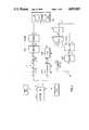
- FIG. 1shows as schematic block diagram of the measuring apparatus according to the present invention
- FIG. 2is part schematic (of a typical channel) and part block diagram of the device including plural measuring channels.
- the measuring deviceincludes detector 11 for detecting the radiation to be measured.
- Detector 11comprises a scintillator which emits light in response to impinging X-ray radiation.
- the scintillatormay be sodium iodide, cesium iodide or other suitable material capable of generating light which is directed to the photodetector 13.
- the photodetectoris optically coupled to scintillator 11 and comprises a photomultiplier tube 12 which coventionally includes a cathode, a plurality of dynodes and an anode.
- the photomultiplier tube 12is biased from separate anode and cathode power supplies 17 and 19.
- a first output 15 of the photodetectoris connected to a first analyzing circuit 16 and a second analyzing circuit 18 is connected to a second output 14 of the photodetector.
- the first analyzing circuit 16detects and counts discrete electronic pulses generated by the photodetector and the second analyzing circuit 18 operates simultaneously for integrating electronic current generated by the photodetector.
- first and second analyzing circuits 16 and 18simultaneously output measuring signals related to the detected radiation.
- the second analyzing circuit 18may provide an inaccurate measuring signal due to the effect of dark currents on the relatively low output signals.
- the first analyzing circuit 16may provide an inaccurate measuring signal due to the pile up effect.
- That objective criterionis one of the measuring signals: Whenever the output M 18 of the second analyzing circuit is above a given threshold T 18 , then the ouput M 16 of the first analyzing circuit can be considered unreliable. Whenever the output M 18 of the second analyzing circuit is below the threshold T 18 , then the output M 18 of the second analyzing circuit can be considered unreliable.
- the signal source for the first analyzing circuit 16is the anode of the photomultiplier tube 12.
- the signal source for the second analyzing circuit 18is one of the photomultiplier dynodes which is operated at ground potential.
- the charge gain from the photocathode to this dynode operated at ground potentialis determined mainly by the photocathode bias and secondarily by the anode bias.
- the charge gain from the grounded dynode to the anodeis determined primarily by the anode bias and secondarily by the photocathode bias.
- the intermediate dynodes of the photomultiplier tube 12are biased from a voltage divider.
- the ohmic values of the components in the voltage dividerare preselected to assure that the linearity of the signal at the second output 14 is not affected when the anode signal saturates.
- the signal at the first output 15 of the photomultiplier tube 12is AC coupled to an input 21 of a charge amplifier 20.
- the charge amplifier 20provides pulse shaping of the arriving signals. Baseline restoration is required to recognize low-amplitude photon emission events among high-amplitude emission events.
- a clamping circuitis provided for sensing negative excursions at the output 23 of the charge amplifier 20 and provides a compensating offset to return these excursions quickly to zero (see FIG. 2).
- Output 23 of charge amplifier 20is connected to an input 25 of a pulse discriminator 22 whose output 27 is conected to the clock input 29 of a binary counter 24.
- the binary counter 24is incremented each time a pulse, corresponding to an X-ray emission event, is detected by the discriminator 22.
- An output 30 from the counter 24is connected to an input 31 of an output register 26 which, under the control of a strobe pulse (NSTROBE), transfers the contents of binary counter 24 to the register 26.
- the strobe pulsesignals the end of a data acquisition interval. After the binary counter is strobed, it is reset to zero (NRSET) for the next data acquisition interval.
- the output 32 from the register 26is transferred to a signal processor (through the I/O buffer 80) at some time during the next following data acquisition interval under the control of the signal processor interface circuits.
- the electronic current generated by the photomultiplier at the output 14is the net of the primary electron current incident on that dynode from the previous dynode and the secondary current emitted to the next following dynode. It is thus of the opposite polarity of the anode signal current.
- the output 14is connected to an input 41 of a charge integrator 40 of the second analyzing circuit 18 for integrating electronic current emitted by the photomultiplier dynode.
- the charge integrator 40has an output 42 connected to an input 44 of sample and hold circuit 45.
- the second analyzing circuitincludes means for detecting overflows of charge integrator 40. It includes a discriminator 50 coupled to the output 42 of the integrator 40 and a binary counter 54 having an input 53 connected to an output 52 of discriminator 50 for counting each overflow occurrence. An output 55 of the binary counter 54 is coupled to register 56 responsive to a control signal for transferring the contents of the binary counter 54 to the register 56 and resetting the binary counter 54.
- Integrator 40is reset at the end of a data acquisition interval by the QRSET signal, but only after the level of the integrator has been sotred in a sample and hold circuit 45.
- the integrator 40may also be reset within a data acquisition interval is discriminator 50 detects that integrator output 42 approaches its full scale value. In that event, an overflow signal increments counter 54. The same signal, via input 43, resets the integrator 40.
- the sample and hold circuit 45has an output 46 connected through multiplexer 60 to a 13 bit analog-to-digital converter (ADC) 64 which is shared among the eight channels in the module.
- ADCanalog-to-digital converter
- the circuitry of channel 1is shown in FIG. 2 and described above. Each channel 2-8 contains components corresponding to channel 1 (except of course the multiplexer 60 and ADC 64 are shared among all channels).
- the output of ADC 64is latched and read out under the control of the signal processor (again through the I/O buffer 80) together with the state of a three-bit register 56 which indicates the number of integrator overflows during the relevant data acquisition interval.
- the overflow indicator bitsprovide the three most significant bits of a 16-bit data word, the ADC 64 provides the 13 least significant bits.
- the I/O buffer 80is part of a data processor 100.
- the data detected and measured by first analyzing means 16 and second analyzing means 18is combined in data processor 100 using correlation calibration data relating equivalent measurements from the two circuits through a correlation coefficient.
- the digital output data of analyzing circuits 16 and 18are transferred via bus 70 and stored in a tristate buffer 80 which is read out to the data processor 100.
- the bus 70is a 16-bit bus.
- Data transfer protocolsare compatible with an MC68000 microprocessor. Direct addressing of 256 data sources (16 in each module) is provided through an on-board address decoder (4 bits) and backplane jumpers (4 bits). Decoding of more significant address bits is accomplished in a separate control module that combines the address strobe signal of the microprocessor with the higher order address bits.
- the data processor 100has available the output of the first analyzing circuit (M 16 ) and the output of the second analyzing circuit (M 18 ). As already described, the data processor 100 determines if M 18 ⁇ T 18 . If M 18 ⁇ T 18 , then M 18 is used by the data processor and M 16 is discarded. On the other hand, if the data processor 100 determines that M 18 ⁇ T 18 , then M 18 is discarded and M 16 is considered valid by the data processor 100. In this fashion, the dynamic range of the measuring device is extended beyond the lower limit of the prior art current integration techniques and beyond the upper limit of the prior art counting techniques. It should be apparent that the preferred embodiment described herein is exemplary only and not limiting; the scope of the invention should be construed in accordance with the claims appended hereto.
Landscapes
- Physics & Mathematics (AREA)
- Health & Medical Sciences (AREA)
- Life Sciences & Earth Sciences (AREA)
- General Physics & Mathematics (AREA)
- High Energy & Nuclear Physics (AREA)
- Molecular Biology (AREA)
- Spectroscopy & Molecular Physics (AREA)
- Measurement Of Radiation (AREA)
Abstract
Description
Claims (14)
Priority Applications (1)
| Application Number | Priority Date | Filing Date | Title |
|---|---|---|---|
| US07/032,692US4893015A (en) | 1987-04-01 | 1987-04-01 | Dual mode radiographic measurement method and device |
Applications Claiming Priority (1)
| Application Number | Priority Date | Filing Date | Title |
|---|---|---|---|
| US07/032,692US4893015A (en) | 1987-04-01 | 1987-04-01 | Dual mode radiographic measurement method and device |
Publications (1)
| Publication Number | Publication Date |
|---|---|
| US4893015Atrue US4893015A (en) | 1990-01-09 |
Family
ID=21866325
Family Applications (1)
| Application Number | Title | Priority Date | Filing Date |
|---|---|---|---|
| US07/032,692Expired - LifetimeUS4893015A (en) | 1987-04-01 | 1987-04-01 | Dual mode radiographic measurement method and device |
Country Status (1)
| Country | Link |
|---|---|
| US (1) | US4893015A (en) |
Cited By (41)
| Publication number | Priority date | Publication date | Assignee | Title |
|---|---|---|---|---|
| US5453610A (en)* | 1994-05-20 | 1995-09-26 | Summit World Trade Corporation | Electronic gain control for photomultiplier used in gamma camera |
| US5512755A (en)* | 1994-05-20 | 1996-04-30 | Summit World Trade Corp. | Gamma camera device |
| US6094472A (en)* | 1998-04-14 | 2000-07-25 | Rapiscan Security Products, Inc. | X-ray backscatter imaging system including moving body tracking assembly |
| FR2803916A1 (en)* | 2000-01-18 | 2001-07-20 | Biospace Instr | Method and device for digitally processing images of an object or patient, obtained using ionizing radiation, in which the signal is optimized whether the signal obtained is of high or low intensity |
| US6507025B1 (en) | 1995-10-23 | 2003-01-14 | Science Applications International Corporation | Density detection using real time discrete photon counting for fast moving targets |
| US6552346B2 (en)* | 1995-10-23 | 2003-04-22 | Science Applications International Corporation | Density detection using discrete photon counting |
| US6661867B2 (en)* | 2001-10-19 | 2003-12-09 | Control Screening, Llc | Tomographic scanning X-ray inspection system using transmitted and compton scattered radiation |
| US6665373B1 (en) | 2002-03-12 | 2003-12-16 | Rapiscan Security Products (Usa), Inc. | X-ray imaging system with active detector |
| US20040251415A1 (en)* | 1995-10-23 | 2004-12-16 | Verbinski Victor V. | Density detection using real time discrete photon counting for fast moving targets |
| US20050089140A1 (en)* | 2001-10-19 | 2005-04-28 | Mario Arthur W. | Tomographic scanning X-ray inspection system using transmitted and compton scattered radiation |
| US7110493B1 (en) | 2002-02-28 | 2006-09-19 | Rapiscan Security Products (Usa), Inc. | X-ray detector system having low Z material panel |
| KR100661862B1 (en) | 2006-04-28 | 2006-12-27 | 한국원자력연구소 | Real time radiation measuring method using a single semiconductor device and its device |
| US20080099689A1 (en)* | 2006-10-31 | 2008-05-01 | Einar Nygard | Photon counting imaging detector system |
| US7388205B1 (en) | 1995-10-23 | 2008-06-17 | Science Applications International Corporation | System and method for target inspection using discrete photon counting and neutron detection |
| US20090147910A1 (en)* | 2007-12-07 | 2009-06-11 | General Electric Company | System and method for energy sensitive computed tomography |
| US20100027738A1 (en)* | 2006-11-30 | 2010-02-04 | Koninklijke Philips Electronics N. V. | Spectral computed tomography using correlated photon number and energy measurements |
| US20100034451A1 (en)* | 2007-06-21 | 2010-02-11 | Hughes Ronald J | Systems and Methods for Improving Directed People Screening |
| US20100102242A1 (en)* | 2008-10-29 | 2010-04-29 | General Electric Company | Multi-layer radiation detector assembly |
| US20100246919A1 (en)* | 2007-12-20 | 2010-09-30 | Koninklijke Philips Electronics N.V. | Radiation detector for counting or integrating signals |
| WO2010109347A1 (en)* | 2009-03-25 | 2010-09-30 | Koninklijke Philips Electronics N.V. | Apparatus and method for data acquisition using an imaging apparatus |
| US7826589B2 (en) | 2007-12-25 | 2010-11-02 | Rapiscan Systems, Inc. | Security system for screening people |
| US20110129063A1 (en)* | 2009-11-18 | 2011-06-02 | Joseph Bendahan | X-Ray-Based System and Methods for Inspecting a Person's Shoes for Aviation Security Threats |
| US8003949B2 (en) | 2007-11-01 | 2011-08-23 | Rapiscan Systems, Inc. | Multiple screen detection systems |
| US8135112B2 (en) | 2007-02-01 | 2012-03-13 | Rapiscan Systems, Inc. | Personnel security screening system with enhanced privacy |
| WO2012079947A1 (en)* | 2010-12-16 | 2012-06-21 | Endress+Hauser Gmbh+Co.Kg | Radiometric measuring device |
| US8314394B1 (en) | 2009-11-04 | 2012-11-20 | Science Applications International Corporation | System and method for three-dimensional imaging using scattering from annihilation coincidence photons |
| US8576982B2 (en) | 2008-02-01 | 2013-11-05 | Rapiscan Systems, Inc. | Personnel screening system |
| US8576989B2 (en) | 2010-03-14 | 2013-11-05 | Rapiscan Systems, Inc. | Beam forming apparatus |
| US8839752B2 (en) | 2011-01-14 | 2014-09-23 | John A. Burrows | Corona igniter with magnetic screening |
| US8995619B2 (en) | 2010-03-14 | 2015-03-31 | Rapiscan Systems, Inc. | Personnel screening system |
| US9285325B2 (en) | 2007-02-01 | 2016-03-15 | Rapiscan Systems, Inc. | Personnel screening system |
| US9632206B2 (en) | 2011-09-07 | 2017-04-25 | Rapiscan Systems, Inc. | X-ray inspection system that integrates manifest data with imaging/detection processing |
| US9891314B2 (en) | 2014-03-07 | 2018-02-13 | Rapiscan Systems, Inc. | Ultra wide band detectors |
| US10134254B2 (en) | 2014-11-25 | 2018-11-20 | Rapiscan Systems, Inc. | Intelligent security management system |
| US10302807B2 (en) | 2016-02-22 | 2019-05-28 | Rapiscan Systems, Inc. | Systems and methods for detecting threats and contraband in cargo |
| US10591424B2 (en) | 2003-04-25 | 2020-03-17 | Rapiscan Systems, Inc. | X-ray tomographic inspection systems for the identification of specific target items |
| US10720300B2 (en) | 2016-09-30 | 2020-07-21 | American Science And Engineering, Inc. | X-ray source for 2D scanning beam imaging |
| US10901112B2 (en) | 2003-04-25 | 2021-01-26 | Rapiscan Systems, Inc. | X-ray scanning system with stationary x-ray sources |
| US10976271B2 (en) | 2005-12-16 | 2021-04-13 | Rapiscan Systems, Inc. | Stationary tomographic X-ray imaging systems for automatically sorting objects based on generated tomographic images |
| US11280898B2 (en) | 2014-03-07 | 2022-03-22 | Rapiscan Systems, Inc. | Radar-based baggage and parcel inspection systems |
| US20220373700A1 (en)* | 2019-10-07 | 2022-11-24 | Paul Scherrer Institut | Dual mode detector |
Citations (32)
| Publication number | Priority date | Publication date | Assignee | Title |
|---|---|---|---|---|
| US2750513A (en)* | 1953-02-27 | 1956-06-12 | Rca Corp | Nuclear radiation measuring instrument |
| US2821633A (en)* | 1955-06-30 | 1958-01-28 | Friedman Herbert | Scintillator |
| US3012140A (en)* | 1959-01-28 | 1961-12-05 | United States Steel Corp | Apparatus for measuring the thickness of a coating on a base material |
| US3082323A (en)* | 1958-06-25 | 1963-03-19 | Ind Nuclconics Corp | Radiation analysis |
| US3088030A (en)* | 1956-12-07 | 1963-04-30 | Jersey Prod Res Co | Scintillator |
| US3114832A (en)* | 1960-07-28 | 1963-12-17 | Radiation Counter Lab Inc | X-ray spectroscopic system comprising plural sources, filters, fluorescent radiators, and comparative detectors |
| US3180985A (en)* | 1962-05-14 | 1965-04-27 | Electronic Automation Systems | Standardization of radiation-absorption type density gages |
| US3193680A (en)* | 1960-10-06 | 1965-07-06 | Herbert L Anderson | Thickness measurement using alpha particles |
| US3210545A (en)* | 1961-07-24 | 1965-10-05 | Industrial Nucleonics Corp | Method of compensating a radiation gauge for unwanted changes in measured material |
| US3379881A (en)* | 1964-11-10 | 1968-04-23 | Commissariat Energie Atomique | Device for the representation in different colors of different radiation intensitiesemitted by an object |
| US3452197A (en)* | 1965-02-24 | 1969-06-24 | American Mach & Foundry | Biological equivalent responsive neutron survey meter |
| US3569708A (en)* | 1967-07-26 | 1971-03-09 | American Mach & Foundry | Straight through and backscatter radiation inspection apparatus for tubular members and method |
| US3733491A (en)* | 1971-07-23 | 1973-05-15 | Eastman Kodak Co | Photomultiplier tube circuit |
| US3866047A (en)* | 1968-08-23 | 1975-02-11 | Emi Ltd | Penetrating radiation examining apparatus having a scanning collimator |
| US3881110A (en)* | 1972-05-17 | 1975-04-29 | Emi Ltd | Penetrating radiation examining apparatus in combination with body locating structure |
| US3922541A (en)* | 1972-12-21 | 1975-11-25 | Schlumberger Technology Corp | Methods and apparatus for stabilizing the gain of a radiation detector |
| US3943458A (en)* | 1974-10-24 | 1976-03-09 | The United States Of America As Represented By The United States Energy Research & Development Administration | Reducing gain shifts in photomultiplier tubes |
| US3946234A (en)* | 1973-08-31 | 1976-03-23 | E M I Limited | Apparatus for examining bodies by means of penetrating radiation |
| US3956633A (en)* | 1974-05-08 | 1976-05-11 | E M I Limited | Radiology method and apparatus |
| US3996467A (en)* | 1974-05-15 | 1976-12-07 | Emi Limited | Data acquisition in tomography |
| US4092539A (en)* | 1976-07-23 | 1978-05-30 | General Electric Company | Radiation monitor |
| US4138640A (en)* | 1975-05-14 | 1979-02-06 | Emi Limited | Measuring arrangements for electrical currents |
| JPS5835481A (en)* | 1981-08-28 | 1983-03-02 | Toshiba Corp | Radiation measurement device |
| US4413183A (en)* | 1980-12-29 | 1983-11-01 | Raytheon Company | Gamma camera |
| US4423329A (en)* | 1980-11-17 | 1983-12-27 | Junta De Energia Nuclear | Gamma radiation detector probe with a halogen-quenched Geiger-Muller tube, compensated for dead time |
| US4486663A (en)* | 1982-05-10 | 1984-12-04 | Siemens Gammasonics, Inc. | Dual integrator for a radiation detector |
| US4588892A (en)* | 1984-09-20 | 1986-05-13 | The United States Of America As Represented By The United States Department Of Energy | Wide-range radiation dose monitor |
| US4599690A (en)* | 1983-11-09 | 1986-07-08 | Siemens Gammasonics, Inc. | Method and circuit for correcting count rate losses of radiation events |
| US4603256A (en)* | 1983-02-14 | 1986-07-29 | U.S. Philips Corporation | Scintillation radiation measuring device comprising a photomultiplier tube, and scintillation camera comprising such a device |
| US4612443A (en)* | 1984-01-27 | 1986-09-16 | Mario Alcidi | Method and device to overcome the pile-up effect in scintillation counters |
| US4767929A (en)* | 1986-10-06 | 1988-08-30 | The United States Of America As Represented By The United State Department Of Energy | Extended range radiation dose-rate monitor |
| US4825077A (en)* | 1986-01-14 | 1989-04-25 | The Harshaw Chemical Company | Process control system and method |
- 1987
- 1987-04-01USUS07/032,692patent/US4893015A/ennot_activeExpired - Lifetime
Patent Citations (32)
| Publication number | Priority date | Publication date | Assignee | Title |
|---|---|---|---|---|
| US2750513A (en)* | 1953-02-27 | 1956-06-12 | Rca Corp | Nuclear radiation measuring instrument |
| US2821633A (en)* | 1955-06-30 | 1958-01-28 | Friedman Herbert | Scintillator |
| US3088030A (en)* | 1956-12-07 | 1963-04-30 | Jersey Prod Res Co | Scintillator |
| US3082323A (en)* | 1958-06-25 | 1963-03-19 | Ind Nuclconics Corp | Radiation analysis |
| US3012140A (en)* | 1959-01-28 | 1961-12-05 | United States Steel Corp | Apparatus for measuring the thickness of a coating on a base material |
| US3114832A (en)* | 1960-07-28 | 1963-12-17 | Radiation Counter Lab Inc | X-ray spectroscopic system comprising plural sources, filters, fluorescent radiators, and comparative detectors |
| US3193680A (en)* | 1960-10-06 | 1965-07-06 | Herbert L Anderson | Thickness measurement using alpha particles |
| US3210545A (en)* | 1961-07-24 | 1965-10-05 | Industrial Nucleonics Corp | Method of compensating a radiation gauge for unwanted changes in measured material |
| US3180985A (en)* | 1962-05-14 | 1965-04-27 | Electronic Automation Systems | Standardization of radiation-absorption type density gages |
| US3379881A (en)* | 1964-11-10 | 1968-04-23 | Commissariat Energie Atomique | Device for the representation in different colors of different radiation intensitiesemitted by an object |
| US3452197A (en)* | 1965-02-24 | 1969-06-24 | American Mach & Foundry | Biological equivalent responsive neutron survey meter |
| US3569708A (en)* | 1967-07-26 | 1971-03-09 | American Mach & Foundry | Straight through and backscatter radiation inspection apparatus for tubular members and method |
| US3866047A (en)* | 1968-08-23 | 1975-02-11 | Emi Ltd | Penetrating radiation examining apparatus having a scanning collimator |
| US3733491A (en)* | 1971-07-23 | 1973-05-15 | Eastman Kodak Co | Photomultiplier tube circuit |
| US3881110A (en)* | 1972-05-17 | 1975-04-29 | Emi Ltd | Penetrating radiation examining apparatus in combination with body locating structure |
| US3922541A (en)* | 1972-12-21 | 1975-11-25 | Schlumberger Technology Corp | Methods and apparatus for stabilizing the gain of a radiation detector |
| US3946234A (en)* | 1973-08-31 | 1976-03-23 | E M I Limited | Apparatus for examining bodies by means of penetrating radiation |
| US3956633A (en)* | 1974-05-08 | 1976-05-11 | E M I Limited | Radiology method and apparatus |
| US3996467A (en)* | 1974-05-15 | 1976-12-07 | Emi Limited | Data acquisition in tomography |
| US3943458A (en)* | 1974-10-24 | 1976-03-09 | The United States Of America As Represented By The United States Energy Research & Development Administration | Reducing gain shifts in photomultiplier tubes |
| US4138640A (en)* | 1975-05-14 | 1979-02-06 | Emi Limited | Measuring arrangements for electrical currents |
| US4092539A (en)* | 1976-07-23 | 1978-05-30 | General Electric Company | Radiation monitor |
| US4423329A (en)* | 1980-11-17 | 1983-12-27 | Junta De Energia Nuclear | Gamma radiation detector probe with a halogen-quenched Geiger-Muller tube, compensated for dead time |
| US4413183A (en)* | 1980-12-29 | 1983-11-01 | Raytheon Company | Gamma camera |
| JPS5835481A (en)* | 1981-08-28 | 1983-03-02 | Toshiba Corp | Radiation measurement device |
| US4486663A (en)* | 1982-05-10 | 1984-12-04 | Siemens Gammasonics, Inc. | Dual integrator for a radiation detector |
| US4603256A (en)* | 1983-02-14 | 1986-07-29 | U.S. Philips Corporation | Scintillation radiation measuring device comprising a photomultiplier tube, and scintillation camera comprising such a device |
| US4599690A (en)* | 1983-11-09 | 1986-07-08 | Siemens Gammasonics, Inc. | Method and circuit for correcting count rate losses of radiation events |
| US4612443A (en)* | 1984-01-27 | 1986-09-16 | Mario Alcidi | Method and device to overcome the pile-up effect in scintillation counters |
| US4588892A (en)* | 1984-09-20 | 1986-05-13 | The United States Of America As Represented By The United States Department Of Energy | Wide-range radiation dose monitor |
| US4825077A (en)* | 1986-01-14 | 1989-04-25 | The Harshaw Chemical Company | Process control system and method |
| US4767929A (en)* | 1986-10-06 | 1988-08-30 | The United States Of America As Represented By The United State Department Of Energy | Extended range radiation dose-rate monitor |
Cited By (78)
| Publication number | Priority date | Publication date | Assignee | Title |
|---|---|---|---|---|
| US5453610A (en)* | 1994-05-20 | 1995-09-26 | Summit World Trade Corporation | Electronic gain control for photomultiplier used in gamma camera |
| US5512755A (en)* | 1994-05-20 | 1996-04-30 | Summit World Trade Corp. | Gamma camera device |
| US5525794A (en)* | 1994-05-20 | 1996-06-11 | Summit World Trade Corp. | Electronic gain control for photomultiplier used in gamma camera |
| US7368717B2 (en) | 1995-10-23 | 2008-05-06 | Science Applications International Corporation | Density detection using real time discrete photon counting for fast moving targets |
| US7388205B1 (en) | 1995-10-23 | 2008-06-17 | Science Applications International Corporation | System and method for target inspection using discrete photon counting and neutron detection |
| US6507025B1 (en) | 1995-10-23 | 2003-01-14 | Science Applications International Corporation | Density detection using real time discrete photon counting for fast moving targets |
| US6552346B2 (en)* | 1995-10-23 | 2003-04-22 | Science Applications International Corporation | Density detection using discrete photon counting |
| US7408160B2 (en) | 1995-10-23 | 2008-08-05 | Science Applications International Corporation | Density detection using real time discrete photon counting for fast moving targets |
| US7365332B2 (en) | 1995-10-23 | 2008-04-29 | Science Applications International Corporation | Density detection using real time discrete photon counting for fast moving targets |
| US7335887B1 (en) | 1995-10-23 | 2008-02-26 | Science Applications International Corporation | System and method for target inspection using discrete photon counting and neutron detection |
| US20040251415A1 (en)* | 1995-10-23 | 2004-12-16 | Verbinski Victor V. | Density detection using real time discrete photon counting for fast moving targets |
| US20060145079A1 (en)* | 1995-10-23 | 2006-07-06 | Science Applications International Corporation | Density detection using real time discrete photon counting for fast moving targets |
| US7045787B1 (en) | 1995-10-23 | 2006-05-16 | Science Applications International Corporation | Density detection using real time discrete photon counting for fast moving targets |
| US20060145080A1 (en)* | 1995-10-23 | 2006-07-06 | Science Applications International Corporation | Density detection using real time discrete photon counting for fast moving targets |
| US6094472A (en)* | 1998-04-14 | 2000-07-25 | Rapiscan Security Products, Inc. | X-ray backscatter imaging system including moving body tracking assembly |
| FR2803916A1 (en)* | 2000-01-18 | 2001-07-20 | Biospace Instr | Method and device for digitally processing images of an object or patient, obtained using ionizing radiation, in which the signal is optimized whether the signal obtained is of high or low intensity |
| US6600161B2 (en) | 2000-01-18 | 2003-07-29 | Biospace Instruments | Method and apparatus for imaging by means of ionizing radiation |
| US20050089140A1 (en)* | 2001-10-19 | 2005-04-28 | Mario Arthur W. | Tomographic scanning X-ray inspection system using transmitted and compton scattered radiation |
| US7072440B2 (en)* | 2001-10-19 | 2006-07-04 | Control Screening, Llc | Tomographic scanning X-ray inspection system using transmitted and Compton scattered radiation |
| US6661867B2 (en)* | 2001-10-19 | 2003-12-09 | Control Screening, Llc | Tomographic scanning X-ray inspection system using transmitted and compton scattered radiation |
| US7110493B1 (en) | 2002-02-28 | 2006-09-19 | Rapiscan Security Products (Usa), Inc. | X-ray detector system having low Z material panel |
| US6665373B1 (en) | 2002-03-12 | 2003-12-16 | Rapiscan Security Products (Usa), Inc. | X-ray imaging system with active detector |
| US11796711B2 (en) | 2003-04-25 | 2023-10-24 | Rapiscan Systems, Inc. | Modular CT scanning system |
| US10901112B2 (en) | 2003-04-25 | 2021-01-26 | Rapiscan Systems, Inc. | X-ray scanning system with stationary x-ray sources |
| US10591424B2 (en) | 2003-04-25 | 2020-03-17 | Rapiscan Systems, Inc. | X-ray tomographic inspection systems for the identification of specific target items |
| US10976271B2 (en) | 2005-12-16 | 2021-04-13 | Rapiscan Systems, Inc. | Stationary tomographic X-ray imaging systems for automatically sorting objects based on generated tomographic images |
| KR100661862B1 (en) | 2006-04-28 | 2006-12-27 | 한국원자력연구소 | Real time radiation measuring method using a single semiconductor device and its device |
| US7829860B2 (en)* | 2006-10-31 | 2010-11-09 | Dxray, Inc. | Photon counting imaging detector system |
| US20080099689A1 (en)* | 2006-10-31 | 2008-05-01 | Einar Nygard | Photon counting imaging detector system |
| US20100027738A1 (en)* | 2006-11-30 | 2010-02-04 | Koninklijke Philips Electronics N. V. | Spectral computed tomography using correlated photon number and energy measurements |
| US7894576B2 (en) | 2006-11-30 | 2011-02-22 | Koninklijke Philips Electronics N.V. | Spectral computed tomography using correlated photon number and energy measurements |
| US9291741B2 (en) | 2007-02-01 | 2016-03-22 | Rapiscan Systems, Inc. | Personnel screening system |
| US9182516B2 (en) | 2007-02-01 | 2015-11-10 | Rapiscan Systems, Inc. | Personnel screening system |
| US9285325B2 (en) | 2007-02-01 | 2016-03-15 | Rapiscan Systems, Inc. | Personnel screening system |
| US8135112B2 (en) | 2007-02-01 | 2012-03-13 | Rapiscan Systems, Inc. | Personnel security screening system with enhanced privacy |
| US20100034451A1 (en)* | 2007-06-21 | 2010-02-11 | Hughes Ronald J | Systems and Methods for Improving Directed People Screening |
| US8199996B2 (en) | 2007-06-21 | 2012-06-12 | Rapiscan Systems, Inc. | Systems and methods for improving directed people screening |
| US8774362B2 (en) | 2007-06-21 | 2014-07-08 | Rapiscan Systems, Inc. | Systems and methods for improving directed people screening |
| US8401147B2 (en) | 2007-11-01 | 2013-03-19 | Rapiscan Systems, Inc. | Multiple screen detection systems |
| US8003949B2 (en) | 2007-11-01 | 2011-08-23 | Rapiscan Systems, Inc. | Multiple screen detection systems |
| US8148693B2 (en) | 2007-11-01 | 2012-04-03 | Rapiscan Systems, Inc. | Multiple screen detection systems |
| US20090147910A1 (en)* | 2007-12-07 | 2009-06-11 | General Electric Company | System and method for energy sensitive computed tomography |
| US7885372B2 (en)* | 2007-12-07 | 2011-02-08 | Morpho Detection, Inc. | System and method for energy sensitive computed tomography |
| US8299440B2 (en) | 2007-12-20 | 2012-10-30 | Koninklijke Philips Electronics N.V. | Radiation detector for counting or integrating signals |
| US20100246919A1 (en)* | 2007-12-20 | 2010-09-30 | Koninklijke Philips Electronics N.V. | Radiation detector for counting or integrating signals |
| US7826589B2 (en) | 2007-12-25 | 2010-11-02 | Rapiscan Systems, Inc. | Security system for screening people |
| US8576982B2 (en) | 2008-02-01 | 2013-11-05 | Rapiscan Systems, Inc. | Personnel screening system |
| US7956332B2 (en) | 2008-10-29 | 2011-06-07 | General Electric Company | Multi-layer radiation detector assembly |
| US20100102242A1 (en)* | 2008-10-29 | 2010-04-29 | General Electric Company | Multi-layer radiation detector assembly |
| US8772726B2 (en) | 2009-03-25 | 2014-07-08 | Koninklijke Philips N.V. | Apparatus and method for data acquisition using an imaging apparatus |
| WO2010109347A1 (en)* | 2009-03-25 | 2010-09-30 | Koninklijke Philips Electronics N.V. | Apparatus and method for data acquisition using an imaging apparatus |
| CN102361593B (en)* | 2009-03-25 | 2014-07-16 | 皇家飞利浦电子股份有限公司 | Apparatus and method for data acquisition using an imaging apparatus |
| US8664609B2 (en) | 2009-11-04 | 2014-03-04 | Leidos, Inc. | System and method for three-dimensional imaging using scattering from annihilation coincidence photons |
| US8426822B1 (en) | 2009-11-04 | 2013-04-23 | Science Application International Corporation | System and method for three-dimensional imaging using scattering from annihilation coincidence photons |
| US8314394B1 (en) | 2009-11-04 | 2012-11-20 | Science Applications International Corporation | System and method for three-dimensional imaging using scattering from annihilation coincidence photons |
| US8654922B2 (en) | 2009-11-18 | 2014-02-18 | Rapiscan Systems, Inc. | X-ray-based system and methods for inspecting a person's shoes for aviation security threats |
| US20110129063A1 (en)* | 2009-11-18 | 2011-06-02 | Joseph Bendahan | X-Ray-Based System and Methods for Inspecting a Person's Shoes for Aviation Security Threats |
| US9058909B2 (en) | 2010-03-14 | 2015-06-16 | Rapiscan Systems, Inc. | Beam forming apparatus |
| US8995619B2 (en) | 2010-03-14 | 2015-03-31 | Rapiscan Systems, Inc. | Personnel screening system |
| US8576989B2 (en) | 2010-03-14 | 2013-11-05 | Rapiscan Systems, Inc. | Beam forming apparatus |
| WO2012079947A1 (en)* | 2010-12-16 | 2012-06-21 | Endress+Hauser Gmbh+Co.Kg | Radiometric measuring device |
| US8839752B2 (en) | 2011-01-14 | 2014-09-23 | John A. Burrows | Corona igniter with magnetic screening |
| US10830920B2 (en) | 2011-09-07 | 2020-11-10 | Rapiscan Systems, Inc. | Distributed analysis X-ray inspection methods and systems |
| US10422919B2 (en) | 2011-09-07 | 2019-09-24 | Rapiscan Systems, Inc. | X-ray inspection system that integrates manifest data with imaging/detection processing |
| US12174334B2 (en) | 2011-09-07 | 2024-12-24 | Rapiscan Systems, Inc. | Distributed analysis X-ray inspection methods and systems |
| US9632206B2 (en) | 2011-09-07 | 2017-04-25 | Rapiscan Systems, Inc. | X-ray inspection system that integrates manifest data with imaging/detection processing |
| US10509142B2 (en) | 2011-09-07 | 2019-12-17 | Rapiscan Systems, Inc. | Distributed analysis x-ray inspection methods and systems |
| US11099294B2 (en) | 2011-09-07 | 2021-08-24 | Rapiscan Systems, Inc. | Distributed analysis x-ray inspection methods and systems |
| US11280898B2 (en) | 2014-03-07 | 2022-03-22 | Rapiscan Systems, Inc. | Radar-based baggage and parcel inspection systems |
| US9891314B2 (en) | 2014-03-07 | 2018-02-13 | Rapiscan Systems, Inc. | Ultra wide band detectors |
| US10713914B2 (en) | 2014-11-25 | 2020-07-14 | Rapiscan Systems, Inc. | Intelligent security management system |
| US10134254B2 (en) | 2014-11-25 | 2018-11-20 | Rapiscan Systems, Inc. | Intelligent security management system |
| US10302807B2 (en) | 2016-02-22 | 2019-05-28 | Rapiscan Systems, Inc. | Systems and methods for detecting threats and contraband in cargo |
| US11287391B2 (en) | 2016-02-22 | 2022-03-29 | Rapiscan Systems, Inc. | Systems and methods for detecting threats and contraband in cargo |
| US10768338B2 (en) | 2016-02-22 | 2020-09-08 | Rapiscan Systems, Inc. | Systems and methods for detecting threats and contraband in cargo |
| US10720300B2 (en) | 2016-09-30 | 2020-07-21 | American Science And Engineering, Inc. | X-ray source for 2D scanning beam imaging |
| US20220373700A1 (en)* | 2019-10-07 | 2022-11-24 | Paul Scherrer Institut | Dual mode detector |
| US11933923B2 (en)* | 2019-10-07 | 2024-03-19 | Paul Scherrer Institut | Dual mode detector |
Similar Documents
| Publication | Publication Date | Title |
|---|---|---|
| US4893015A (en) | Dual mode radiographic measurement method and device | |
| EP2513670B1 (en) | Radiation detection system and method of analyzing an electrical pulse output by a radiation detector | |
| US7642518B1 (en) | Stabilization of a scintillation detector | |
| US4181855A (en) | Method and apparatus for determining random coincidence count rate in a scintillation counter utilizing the coincidence technique | |
| US10048393B2 (en) | Gain stabilization of photomultipliers | |
| JPH07146371A (en) | Signal processing method and scintillation camera | |
| US6858847B1 (en) | Circuit and method for energy discrimination of coincident events in coincidence detecting gamma camera system | |
| US4071761A (en) | Method for determining random coincidence count rate in a scintillation counter utilizing the coincidence technique | |
| EP0117299B1 (en) | Radiation imaging apparatus | |
| GB1145713A (en) | Method and apparatus for counting standardization in scintillation spectrometry | |
| US7394072B2 (en) | Gamma camera calibration and diagnosis using pulse injection | |
| US3842278A (en) | Liquid scintillation unit with low background noise | |
| US5410153A (en) | Position calculation in a scintillation camera | |
| JPH04270984A (en) | Position detector | |
| US3800143A (en) | Agc for radiation counter | |
| US5367168A (en) | Method for discrimination and simultaneous or separate measurement of single or multiple electronic events in an opto-electronic detector | |
| US3184597A (en) | Stabilized scintillation detector | |
| US4415982A (en) | Scintillation camera | |
| KR20230041175A (en) | Method for temperature compensation of radiation spectrum | |
| US4468744A (en) | Scintillation camera | |
| JP2001194460A (en) | Radiation monitor | |
| RU2251124C1 (en) | Electron and beta-radiation scintillation detector | |
| EP3286583B1 (en) | Gamma system count loss correction with virtual pulse injection | |
| Radtke | A fast scintillation detector for analytical X-ray instruments | |
| Salomon et al. | A multi-anode photomultiplier with position sensitivity |
Legal Events
| Date | Code | Title | Description |
|---|---|---|---|
| AS | Assignment | Owner name:AMERICAN SCIENCE AND ENGINEERING, INC.,MASSACHUSET Free format text:ASSIGNMENT OF ASSIGNORS INTEREST;ASSIGNORS:KUBIERSCHKY, KLAUS;ARONSON, HERBERT L.;SIGNING DATES FROM 19870306 TO 19870320;REEL/FRAME:004687/0047 Owner name:AMERICAN SCIENCE AND ENGINEERING, INC., FT. WASHIN Free format text:ASSIGNMENT OF ASSIGNORS INTEREST.;ASSIGNORS:KUBIERSCHKY, KLAUS;ARONSON, HERBERT L.;REEL/FRAME:004687/0047;SIGNING DATES FROM 19870306 TO 19870320 | |
| STCF | Information on status: patent grant | Free format text:PATENTED CASE | |
| AS | Assignment | Owner name:UNITED STATES TRUST COMPANY, 30/40 COURT ST., BOST Free format text:ASSIGNMENT OF ASSIGNORS INTEREST.;ASSIGNOR:AMERICAN SCIENCE AND ENGINEERING, INC., A CORP. OF MA.;REEL/FRAME:005513/0323 Effective date:19900703 | |
| FEPP | Fee payment procedure | Free format text:PAYOR NUMBER ASSIGNED (ORIGINAL EVENT CODE: ASPN); ENTITY STATUS OF PATENT OWNER: SMALL ENTITY | |
| FPAY | Fee payment | Year of fee payment:4 | |
| FEPP | Fee payment procedure | Free format text:PAYER NUMBER DE-ASSIGNED (ORIGINAL EVENT CODE: RMPN); ENTITY STATUS OF PATENT OWNER: SMALL ENTITY Free format text:PAYOR NUMBER ASSIGNED (ORIGINAL EVENT CODE: ASPN); ENTITY STATUS OF PATENT OWNER: SMALL ENTITY | |
| FPAY | Fee payment | Year of fee payment:8 | |
| AS | Assignment | Owner name:AMERICAN SCIENCE AND ENGINEERING, INC., MASSACHUSE Free format text:ASSIGNMENT OF ASSIGNORS INTEREST;ASSIGNOR:UNITED STATES TRUST COMPANY;REEL/FRAME:011137/0190 Effective date:20001128 | |
| AS | Assignment | Owner name:EXPORT-IMPORT BANK OF THE UNITED STATES, DISTRICT Free format text:SECURITY AGREEMENT;ASSIGNOR:AMERICAN SCIENCE AND ENGINEERING, INC.;REEL/FRAME:011277/0608 Effective date:20001130 | |
| FPAY | Fee payment | Year of fee payment:12 | |
| AS | Assignment | Owner name:SILICON VALLEY BANK DBA SILICON VALLEY EAST, CALIF Free format text:SEURITY AGREEMENT;ASSIGNOR:AMERICAN SCIENCE AND ENGINEERING, INC.;REEL/FRAME:014007/0604 Effective date:20030811 | |
| AS | Assignment | Owner name:AMERICAN SCIENCE AND ENGINEERING, INC., MASSACHUSE Free format text:ASSIGNMENT OF ASSIGNORS INTEREST;ASSIGNOR:SILICON VALLEY BANK;REEL/FRAME:023556/0062 Effective date:20091118 |