US4891991A - Coriolis-type mass flowmeter - Google Patents
Coriolis-type mass flowmeterDownload PDFInfo
- Publication number
- US4891991A US4891991AUS06/923,847US92384786AUS4891991AUS 4891991 AUS4891991 AUS 4891991AUS 92384786 AUS92384786 AUS 92384786AUS 4891991 AUS4891991 AUS 4891991A
- Authority
- US
- United States
- Prior art keywords
- section
- conduit
- coriolis
- drive
- flowmeter
- Prior art date
- Legal status (The legal status is an assumption and is not a legal conclusion. Google has not performed a legal analysis and makes no representation as to the accuracy of the status listed.)
- Expired - Lifetime
Links
Images


Classifications
- G—PHYSICS
- G01—MEASURING; TESTING
- G01F—MEASURING VOLUME, VOLUME FLOW, MASS FLOW OR LIQUID LEVEL; METERING BY VOLUME
- G01F1/00—Measuring the volume flow or mass flow of fluid or fluent solid material wherein the fluid passes through a meter in a continuous flow
- G01F1/76—Devices for measuring mass flow of a fluid or a fluent solid material
- G01F1/78—Direct mass flowmeters
- G01F1/80—Direct mass flowmeters operating by measuring pressure, force, momentum, or frequency of a fluid flow to which a rotational movement has been imparted
- G01F1/84—Coriolis or gyroscopic mass flowmeters
- G01F1/8409—Coriolis or gyroscopic mass flowmeters constructional details
- G01F1/8413—Coriolis or gyroscopic mass flowmeters constructional details means for influencing the flowmeter's motional or vibrational behaviour, e.g., conduit support or fixing means, or conduit attachments
- G—PHYSICS
- G01—MEASURING; TESTING
- G01F—MEASURING VOLUME, VOLUME FLOW, MASS FLOW OR LIQUID LEVEL; METERING BY VOLUME
- G01F1/00—Measuring the volume flow or mass flow of fluid or fluent solid material wherein the fluid passes through a meter in a continuous flow
- G01F1/76—Devices for measuring mass flow of a fluid or a fluent solid material
- G01F1/78—Direct mass flowmeters
- G01F1/80—Direct mass flowmeters operating by measuring pressure, force, momentum, or frequency of a fluid flow to which a rotational movement has been imparted
- G01F1/84—Coriolis or gyroscopic mass flowmeters
- G01F1/8409—Coriolis or gyroscopic mass flowmeters constructional details
- G01F1/8431—Coriolis or gyroscopic mass flowmeters constructional details electronic circuits
- G—PHYSICS
- G01—MEASURING; TESTING
- G01F—MEASURING VOLUME, VOLUME FLOW, MASS FLOW OR LIQUID LEVEL; METERING BY VOLUME
- G01F1/00—Measuring the volume flow or mass flow of fluid or fluent solid material wherein the fluid passes through a meter in a continuous flow
- G01F1/76—Devices for measuring mass flow of a fluid or a fluent solid material
- G01F1/78—Direct mass flowmeters
- G01F1/80—Direct mass flowmeters operating by measuring pressure, force, momentum, or frequency of a fluid flow to which a rotational movement has been imparted
- G01F1/84—Coriolis or gyroscopic mass flowmeters
- G01F1/8409—Coriolis or gyroscopic mass flowmeters constructional details
- G01F1/8436—Coriolis or gyroscopic mass flowmeters constructional details signal processing
- G—PHYSICS
- G01—MEASURING; TESTING
- G01F—MEASURING VOLUME, VOLUME FLOW, MASS FLOW OR LIQUID LEVEL; METERING BY VOLUME
- G01F1/00—Measuring the volume flow or mass flow of fluid or fluent solid material wherein the fluid passes through a meter in a continuous flow
- G01F1/76—Devices for measuring mass flow of a fluid or a fluent solid material
- G01F1/78—Direct mass flowmeters
- G01F1/80—Direct mass flowmeters operating by measuring pressure, force, momentum, or frequency of a fluid flow to which a rotational movement has been imparted
- G01F1/84—Coriolis or gyroscopic mass flowmeters
- G01F1/845—Coriolis or gyroscopic mass flowmeters arrangements of measuring means, e.g., of measuring conduits
- G01F1/8468—Coriolis or gyroscopic mass flowmeters arrangements of measuring means, e.g., of measuring conduits vibrating measuring conduits
- G01F1/8481—Coriolis or gyroscopic mass flowmeters arrangements of measuring means, e.g., of measuring conduits vibrating measuring conduits having loop-shaped measuring conduits, e.g. the measuring conduits form a loop with a crossing point
- G01F1/8486—Coriolis or gyroscopic mass flowmeters arrangements of measuring means, e.g., of measuring conduits vibrating measuring conduits having loop-shaped measuring conduits, e.g. the measuring conduits form a loop with a crossing point with multiple measuring conduits
Definitions
- the present inventionrelates generally to Coriolis-type mass flowmeters and in particular to mass flowmeters employing oscillating conduits.
- volumetric flowmetersIn response to the need to measure the quantity of material being delivered through pipelines, numerous types of flowmeters have evolved from a variety of design principles. One of the more widely used types of flowmeters is based on volumetric flow. Some designs employ turbines in the flow line; others operate on a resilient vane principle. Of course, volumetric flowmeters are at best inaccurate in determining the quantity of material delivered, where the density of the material varies with temperature or feedstock or where the fluid being pumped through the pipe line is polyphase such as a slurry or where the fluid is non-Newtonian such as mayonnaise and other food products. In the petroleum field, so called “custody transfer" requires accurate measurement of the exact amount of oil or gasoline being transferred through the pipeline. The higher the price of oil, the more costly the inaccuracy of the flow measurement. In addition, chemical reactions, which are in effect mass reactions where proportions are critical, may be poorly served by volumetric flowmeters.
- the present inventionis concerned with improvements in one type of direct mass measuring flowmeter referred to in the art as a Coriolis effect flowmeter.
- Coriolis forcesare exhibited in the radial movement of mass on a rotating surface.
- a planar surfacerotating at constant angular velocity about an axis perpendicularly intersecting the surface.
- a mass travelling at what appears to be a constant linear speed radially outward on the surfaceactually speeds up in the tangential direction.
- the change in velocityimplies that the mass has been accelerated.
- the acceleration of the massgenerates a reaction force in the plane of rotation perpendicular to the instantaneous radial movement of the mass.
- the Coriolis force vectoris the cross-product of the angular velocity vector (parallel to the rotational axis) and the velocity vector of the mass in the direction of its travel with respect to the axis of rotation (e.g., radial).
- Mass flowmeters in the prior art which induce a Coriolis force by rotationfall into two categories: continuously rotating and oscillating.
- the principal functional difference between these two typesis that the oscillating version, unlike the continuously rotating one, has periodically (i.e., usually sinusoidally) varying angular velocity producing, as a result, a continuously varying level of Coriolis force.
- a major difficulty in oscillatory systemsis that the effect of the Coriolis force is relatively small compared not only to the drive force but also to extraneous vibrations.
- an oscillatory systemcan employ the bending resiliency of the pipe itself as a hinge or pivot point for oscillation and thus obviate separate rotary or flexible joints.
- the general purpose of the inventionis to improve the performance of Coriolis-type mass flowmeters by optimizing the overall design of the flowmeter.
- a more specific goalis to eliminate or lessen some of the shortcomings of prior art mass flowmeters to make them more reliable, more compact and less susceptible to interference from extraneous loads and, of course, more accurate, without unduly increasing the complexity or manufacturing cost of the meter.
- a rigid central blocksupports at least one loop of tubing connected via the block to an inlet and outlet of the meter.
- the inlet and outlet ends of the loop itselfare preferably connected to the block by respective straight parallel conduit legs closely spaced to each other and rigidly connected to the block at their proximal ends.
- the loopincludes a straight section preferably perpendicular to the inlet and outlet legs.
- the parallel inlet/outlet legsought to be substantially perpendicular to the orthogonal projection of the straight section onto the plane defined by the legs.
- the respective ends of the straight sectionare connected to the inlet and outlet by means of side sections or lobes.
- the side sectionsare sloping and straight, forming an overall configuration like a coat hanger except for the parallel inlet/outlet legs.
- Drive meansare provided for oscillating the straight section back and forth about its perpendicular bisector, preferably an axis of symmetry for the loop.
- Complementary position detectors employed at or near the opposite ends of the straight sectionprovide readouts which are combined algebraically to yield a Coriolis-related term.
- complementary dual drive unitsare located at opposite ends of the straight section and impart to it oscillatory motion about the perpendicular bisector axis. The intermediate portion of the straight section is thus left free.
- corresponding drive units and position detectorsare located at approximately the same point along the loop to drive and detect the same type of motion.
- a second loop parallel to the firstis supported by the same block.
- the second loopis preferably identical to the first and lies in a closely spaced parallel plane.
- the blockis channeled to serve as a manifold and coupled to the process line.
- Incoming fluidenters an intake manifold ported through the block to at least one of the inlet ends of the two loops. At least one of the outlet ends of the loops is ported through the block to an outlet manifold which is reconnected into the pipeline.
- the blockthus serves not only as mechanical ground for each of the loops but also as a manifold. However, the block can be channeled for series or parallel flow. The flow direction in the loops is preferably the same.
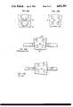
- FIG. 1is an oblique isometric view of a double loop, dual drive, central manifold, Coriolis effect mass flowmeter according to the invention.
- FIG. 2Ais a plan schematic fragmentary view like that of FIG. 2 with a series flow manifold block.
- FIG. 3is a side schematic view in elevation of the apparatus of FIG. 2 taken in the indicated direction along lines 3--3.
- FIG. 4is a side elevational view of the apparatus of FIG. 1 in more detail with portions of the central manifold assembly broken away to reveal the inlet and outlet chambers.
- FIG. 5is a sectional view with portions in plan taken in the direction indicated along the lines 5--5 of FIG. 4.
- FIG. 6is a side elevational view of the central manifold assembly with the tubes and support arm in section taken in the direction indicated along the lines 6--6 of FIG. 4.
- FIG. 7is a plan view of an in-line embodiment of a double loop, dual drive Coriolis effect mass flowmeter, according to the invention, in which the planes of the loops are oriented parallel to the process line.
- FIG. 8is a side elevational view of the apparatus of FIG. 7.
- FIG. 9is a schematic representation of three modes of motion of the apparatus of FIGS. 1 and 7.
- FIGS. 10A and 10Bare contrasting schematic representations of dual and single node plates respectively undergoing exaggerated torsional in-plane deflection.
- FIGS. 11A and 11Bare contrasting schematic representations of the effect of exaggerated torsional deflection on the pipeline connected to the casting 16 in the perpendicular and in-line embodiments, respectively.
- a specific tubular configurationis described herein in two orientations, perpendicular and in-line with respect to the direction of the process flow, i.e., the direction of flow in a straight section of pipeline in which the meter is to be inserted.
- the implementations illustrated hereinare designed for one inch pipelines for a variety of products including petroleum based fuels, for example.
- the inventionis applicable to a wide variety of other specific designs for the same or different applications.
- FIG. 1illustrates a double loop, dual drive/detector system with torsional loading of the tube ends where they are connected to a single rigid central manifold connected in line with the process flow. The same embodiment is shown in FIGS. 1, 2 and 3-6 with more detail being provided in FIGS. 4-6.
- the ends of loop 18comprise straight preferably vertical parallel inlet and outlet sections or legs 22 and 24 securely affixed, e.g., by butt welding, to the top of the manifold 16a in close proximity to each other.
- the base of loop 18is a long straight section 26 passing freely through an undercut channel 28 in the bottom face of the casting 16.
- the long straight section 26 at the base of the loop 18is connected to the upright legs 22 and 24 by respective diagonal sections 30 and 32.
- the four junctions between the various straight segments of the loop 18are rounded by large radii turns to afford as little resistance to flow as possible.
- upright legs 22 and 24are connected to the respective diagonal segments 30 and 32 by means of apex turns 34 and 36 respectively.
- the ends of the long straight base section 26are connected to the respective ends of the diagonal segments 30 and 32 by lower rounded turns 38 and 40.
- the parallel inlet/outlet ends 22, 24 of both loops 18 and 20pass through a correspondingly apertured isolation plate or node plate 41 which is parallel to surface 16a and spaced therefrom by a predetermined distance, for example, 0.825 inch in a one-inch pipe embodiment.
- the node plateserves as a stress isolation bar and defines a common mechanical ground for each loop.
- node plate 41as mechanical ground compared to the casting 16 is that the interconnection of the plate and inlet/outlet legs 22, 24 is by way of completely external circular weldments on the upper and lower surfaces of the plate, forming two external rings around each leg.
- the butt welds of the tube ends to the bosses on the casting 16are exposed on the interior to the process fluid which will tend in time to corrode the weldments faster if they are in constantly reversing torsional stress.
- Manifold casting 16is channeled inside so that the inlet stream is diverted in parallel to upright legs 22 of loops 18 and 20 as shown in FIG. 2.
- the loop outlet from upright legs 24is combined and diverted to the outlet of the meter, back to the pipeline 10.
- the loops 18 and 20are thus connected in parallel flow-wise as well as geometry-wise.
- FIG. 2Ashows a variation in which the channels in manifold block 16' are modified for series flow through the loops. Blocks 16 and 16' are otherwise interchangeable.
- the manifold casting 16is shown in FIGS. 4 and 5.
- a pair of offset overlapping channels 42 and 44, parallel to the process line,are connected to the respective integral inlet and outlet pipe sections 10' by means of larger offset openings 46 and 48.
- Channels 42 and 44are in communication respectively with the inlet and outlet of the meter to form intake and exhaust manifolds.
- a pair of vertical spaced ports 52 through the casting 16communicate the inlet legs 22 of the loops 18 and 20 with the intake manifold formed by channel 42.
- a pair of vertical spaced ports 54communicate the upright outlet legs 24 of loops 18 and 20 with the exhaust manifold formed by channel 44.
- the ends of the two pairs of upright legs 22 and 24are butt welded to hollow conical bosses 56 rising integrally from the casting coaxially with respective ports 52 and 54.
- the electrical driver/detector assembliesare supported independently on the outboard ends of rigid opposed arms 60 and 62 in the form of T-beams securely attached to opposite faces of the manifold casting 16 by disk shaped mounting flanges 64. Flanges 64 and casting 16 may be matingly keyed as shown in FIG. 5 for extra stability.
- Cantilevered arms 60 and 62extend parallel within the planes of the two loops 18 and 20 and the vertical plates of the arms pass between the corners 38 and 40 where the driver/detector assemblies are located for both loops.
- each cantilevered arm 60, 62two identical solenoid type driver assemblies 70 are located and held in position by driver brackets 72.
- Each drivercomprises a pair of solenoid coils and pole pieces 74 which act on ferromagnetic slugs 76 welded onto opposite sides of the lower turn 38, 40.
- Each driverimparts reciprocal sideways motion to the tube between the slugs 76.
- straight section 26is caused to rotate about its coplanar perpendicular bisector 79 which intersects the tube at point c as shown in FIG. 1.
- the drive rotationis thus preferably in a horizontal plane about point c.
- the perpendicular bisectors for the straight sections of both loopspreferably lie in a common plane of symmetry for both loops as noted in FIG. 1.
- the energizing current of the complementary drives 70causes the straight section 26 of the loop 18 to execute an oscillatory motion about point c in the horizontal plane.
- the motion of each straight section 26sweeps out a bow tie shape.
- the entire lateral excursion of the loop at the corners 38 and 40is small, on the order of 1/8 of an inch for a two foot long straight section 26 for a one inch pipe.
- This displacementis coupled to the upright parallel legs 22 and 24 as torsional deflection about the axes of the legs 22 and 24 beginning at the node plate 41.
- the same type of oscillatory motionis induced in the straight section of the loop 20 by the other respective pair of complementary drives 70 supported on the outer ends of the upper deck of the cantilevered arms 60 and 62, respectively.
- the central vertical portion of the T-beamextends between the corners 38 and 40 of the two loops 18 and 20, respectively, and supports detector assemblies 80 on brackets 82 at the respective ends of the arms 60 and 62.
- Each of the four detector assemblies 80includes a position, velocity or acceleration sensor, for example, a variable differential transformer having a pair of coils mounted on the stationary bracket 82 and a movable element between the coils affixed to the tube corner 38, 40.
- the movable elementis connected to a strap welded to the corner 38, 40 of the loop as shown.
- Conventional optical, capacitive or linear variable displacement transducers (LVDT's)may be substituted.
- the position detectorprefferably has an output that is linear with respect to displacement over the limited deflection range and relatively insensitive to motions substantially skewed with respect to the plane of the respective loop.
- the implementation of the detectoris a matter of design choice and does not form a part of the present invention.
- the driver detector assembly pairs 70, 80 for loop 18are designated A and B corresponding to the opposite ends of the straight section 26 of loop 18.
- the driver/detector assemblies for the other parallel loop 20are designated C and D for the left and right ends as viewed in the drawing.
- FIGS. 7 and 8An alternate embodiment of the same parallel loop configuration shifted 90° is shown in FIGS. 7 and 8.
- the planes of the loops 18 and 20are arranged parallel to the process flow direction.
- In-line pipe section 10" connecting the mounting flange to the somewhat abbreviated manifold casting 16is extended (or connected to another pipe segment) to traverse the entire length of one side of the loops 18 and 20.
- the motion of the loops and location of the node plate and driver/detector assembliesare identical to those in the perpendicular embodiment of FIG. 1.
- the driver/detector assembly arms 60' and 62'may, if desired, be supported over their entire length by the respective pipe section 10".
- the resonant frequency of the Coriolis motion and common mode motionshould be determined by design configuration to be different from the resonant frequency of the oscillatory motion of the straight section, i.e., the drive mode.
- node plate 41 in FIG. 1The further the displacement of the node plate 41 in FIG. 1 from the casting 16, the higher the resonant frequency of the loop in the drive mode. However, the node plate also tends to reduce the Coriolis effect displacement, the farther the plate is spaced from the casting 16.
- Two node plates 41a and 41bcan be employed linking corresponding ends of the loops as shown in FIG. 10A. Using one plate, however, as shown in FIG. 1 and 10B, may provide better isolation. In either case as the distance of the node plate or plates from the manifold increases, the meter becomes less sensitive to Coriolis mode and requires more drive force for the same tube configuration.
- the in-line version of FIG. 7 and 8has a possible advantage over the perpendicular model of FIG. 1 which is illustrated in Figs. 11A and 11B.
- the torsional stress on the casting 16tends to distort the casting slightly by placing face 16b in tension and face 16c in compression skewing the faces to which the process line is connected.
- the manifold casting 16bends less than the node plate or plates shown in FIG. 10A and 10B, a slight transverse oscillation of the pipeline from side to side could arise as illustrated in FIG. 11A.
- the in-line designmay be less susceptible since the pipeline is connected to faces 16b and 16c which deflect more in parallel than the other two faces, as illustrated in FIG. 11B.
- the magnitude of the torsional stress of the castingin either case is reduced by employing a node plate or plates.
- the sensing and control schemeemploys dual sensors and dual drivers corresponding to the ends of each loop.
- positions A and B at the lower corners 38 and 40are occupied by respective sensors and drivers
- positions C and D at the ends of the lower straight section of loop 20are occupied by corresponding sensors and drivers.
- the four position sensorspreferably variable differential transformers, are excited by a 30 kHz sine wave from oscillator 100.
- the outputs of the transformer coilsare demodulated by respective amplitude demodulators 102 and fed to sum and difference circuits as shown.
- the output voltage of sensor Awill be of the form:
- the output of the B sensorwill be of the form:
- the sine termrepresents the drive mode motion and the cosine term 90° out of phase with the sine term, represents the Coriolis mode motion.
- the difference of these voltage signalsdoubles the drive signal and cancels the Coriolis term.
- the sum of these voltage signalsdoubles the Coriolis term and cancels the drive signal.
- the derivative of the drive term DRV1 out of differentiator 104transforms the signal to the cosine which is used as the drive signal.
- a similar sine drive mode term (DRV2)is derived from loop 20's position sensors C and D and compared, if necessary, with the drive mode term from loop 18 in phase lock servo 106.
- the error signal from circuit 106is used in phase control block 108 as a control signal to rotate the phase if necessary by adding back a little of the sine component to the derivative term.
- the drive mode term (sine) DRV1is compared with a DC reference by an amplitude servo 110 and fed to gain control amplifier 112 to adjust the amplitude of the drive signal to the driver 70 to maintain average amplitude of the drive output term constant
- the amplitude of the sine drive mode termcan be allowed to vary and simply be monitored and ratioed in the output of the drive circuit.
- the phase and gain adjusted signalis compared to the drive mode damping signal from the differentiator 104 and fed via summer 114 and an amplifier to force driver A on loop 18.
- Summer 114adds in a Coriolis mode term and a common mode damping term if necessary.
- Coriolis mode dampinguses the cosine term COR1 or COR2 to drive in the Coriolis mode in opposite direction at the Coriolis mode resonant frequency in response to a spurious increase in Coriolis mode motion due, for example, to centrifugal acceleration of the flow.
- Common mode dampingis provided by summing the reverse Coriolis terms COR1 and COR2 from the respective loops to see if they are other than in the opposite direction, i.e., if they are not equal and opposite This term is added to the Coriolis term before compensating the drive signal in summer 114.
- the B force driver signalis derived in exactly the same way except that the drive mode signal is reversed.
- the drive signals for drivers C and D on loop 20are similarly derived in a corresponding manner.
- the output signal designed to track Coriolis mode motionis derived by summing the magnitude of the Coriolis terms and using the 90° out of phase drive mode motion signals to produce a quadrature reference 116 which is used in a synchronous demodulator 118 which compares the Coriolis terms to the phase of the drive signal
- the output of the demodulator 118is passed via a low pass filter to remove noise.
- the synchronous demodulation steppurifies the Coriolis term by removing components in phase with the drive signal.
- the general configuration of the loop or loopsis not restricted to the "coat hanger" design of the detailed embodiment.
- Other configurations besides the "coat hanger”can be designed to embody the principle of an oscillating straight section with ends connected via side sections or lobes to respective parallel inlet/outlet legs 1 1 and 1 2 which are approximately perpendicular to the orthogonal projection s' of the straight section s in the plane of the legs as illustrated in FIG. 13.
- the coat hanger designis considered to be a special case of the design principle of FIG. 13.
- FIG. 14shows another substantially planar loop design embodying this principle.
- the parameters of width A, straight section length B, height C and radius Rcan be varied to achieve different operating characteristics.
- the independently controlled dual drive system for each loopeliminates imbalances and deflections along the length of the straight section 26 which could be caused by a single oscillatory drive on the axis 80 and permits separate control of both ends to perfect the motion. Having the detectors right at the drivers insures that the system drives and senses the correct mode.
- the overall symmetry of the configurationadds to its stability.
- the rigid central manifoldacts with the node plate as mechanical ground while the two pairs of straight legs 22, 24 in complementary torsion exhibit a tuning fork effect in combination with the rigid block to reduce vibration of the block itself. Because of the orthogonal orientation of the loops, the axial pipeline length consumed by the meter of FIG.
- FIG. 71-6 is minimized as shown by length 1 in FIG. 2.
- the extension of the meteri.e., the transverse width w' as shown in FIG. 7 is greatly reduced
- the in-line embodiment of FIGS. 7 and 8may also tend to eliminate zero offset better than the perpendicular version, i.e., when the flow is stopped.
- the oscillation of the straight section 26exhibits a total linear displacement at each end far less than the diameter of the pipe segment.
- the excursionhas been approximately on the order of 10% of the diameter of the pipe.
- the loop orientationcan be rotated 90° so that the long straight section 26 is vertical if desired.
- many other orientations of the loopare possible without necessarily affecting the operation of the meter.
- the symmetry of the devicecan be changed, it is desirable since it allows reversal of components without affecting the operation of the instrument.
- the metercan be produced in parallel flow loops as shown in the drawings or in series flow for low flow rates by simply stocking parallel and series manifolds.
- arms 60 and 62are not essential; the detector and drive assemblies can be mounted directly to the loops themselves although the meter might be more susceptible to common mode motion.
- the push/pull type drive units referred to herein and also not necessarily required as other suitable means of imparting oscillatory motionmay be found to be satisfactory.
Landscapes
- Physics & Mathematics (AREA)
- Fluid Mechanics (AREA)
- General Physics & Mathematics (AREA)
- Engineering & Computer Science (AREA)
- Signal Processing (AREA)
- Measuring Volume Flow (AREA)
- Polyesters Or Polycarbonates (AREA)
Abstract
Description
VA=A.sub.D sin ωt+A.sub.C cos ωt
V.sub.B =-A.sub.D sin ωt+A.sub.C cos ωt
Claims (38)
Priority Applications (20)
| Application Number | Priority Date | Filing Date | Title |
|---|---|---|---|
| KR1019880700745AKR960000099B1 (en) | 1986-10-28 | 1986-10-21 | Coriolis type mass flow meter |
| US06/923,847US4891991A (en) | 1986-10-28 | 1986-10-28 | Coriolis-type mass flowmeter |
| AT87907556TATE139335T1 (en) | 1986-10-28 | 1987-10-21 | CORIOLIST TYPE MASS FLOW METER |
| DE3751835TDE3751835T2 (en) | 1986-10-28 | 1987-10-21 | CORIOLISTYP MASS FLOW METER |
| JP62507027AJPH02501006A (en) | 1986-10-28 | 1987-10-21 | Coriolis style mass flow meter |
| EP87907556AEP0329700B1 (en) | 1986-10-28 | 1987-10-21 | Coriolis-type mass flowmeter |
| EP95115536AEP0696726A3 (en) | 1986-10-28 | 1987-10-21 | Coriolis mass flow meter |
| AU82743/87AAU619450B2 (en) | 1986-10-28 | 1987-10-21 | Coriolis-type mass flowmeter |
| PCT/US1987/002759WO1988003261A1 (en) | 1986-10-28 | 1987-10-21 | Coriolis-type mass flowmeter |
| CA000550304ACA1330725C (en) | 1986-10-28 | 1987-10-27 | Coriolis-type mass flowmeter |
| CN87107806ACN1021084C (en) | 1986-10-28 | 1987-10-28 | Coriolis-type mass flowmeter |
| US07/116,257US4911020A (en) | 1986-10-28 | 1987-10-29 | Coriolis-type mass flowmeter circuitry |
| DK352788ADK352788A (en) | 1986-10-28 | 1988-06-27 | MASS POWER FLOW TARGETS |
| NO882833ANO882833L (en) | 1986-10-28 | 1988-06-27 | CORIOLIS TYPE FLOW METER. |
| FI892013AFI892013A7 (en) | 1986-10-28 | 1989-04-27 | MASSFLOEDESMAETARE AV CORIOLIS-TYPE. |
| US07/420,569US5050439A (en) | 1986-10-28 | 1989-10-12 | Coriolis-type mass flowmeter circuitry |
| AU15217/92AAU658877B2 (en) | 1986-10-28 | 1992-04-28 | Coriolis-type mass flowmeter |
| AU15216/92AAU658876B2 (en) | 1986-10-28 | 1992-04-28 | Coriolis-type mass flowmeter |
| US07/879,156US5343764A (en) | 1986-10-28 | 1992-04-30 | Coriolis-type mass flowmeter |
| US07/954,685US5271281A (en) | 1986-10-28 | 1992-09-30 | Coriolis-type mass flowmeter |
Applications Claiming Priority (1)
| Application Number | Priority Date | Filing Date | Title |
|---|---|---|---|
| US06/923,847US4891991A (en) | 1986-10-28 | 1986-10-28 | Coriolis-type mass flowmeter |
Related Child Applications (3)
| Application Number | Title | Priority Date | Filing Date |
|---|---|---|---|
| US07/116,257Continuation-In-PartUS4911020A (en) | 1986-10-28 | 1987-10-29 | Coriolis-type mass flowmeter circuitry |
| US46262390ADivision | 1986-10-28 | 1990-01-08 | |
| US07/879,156DivisionUS5343764A (en) | 1986-10-28 | 1992-04-30 | Coriolis-type mass flowmeter |
Publications (1)
| Publication Number | Publication Date |
|---|---|
| US4891991Atrue US4891991A (en) | 1990-01-09 |
Family
ID=25449350
Family Applications (1)
| Application Number | Title | Priority Date | Filing Date |
|---|---|---|---|
| US06/923,847Expired - LifetimeUS4891991A (en) | 1986-10-28 | 1986-10-28 | Coriolis-type mass flowmeter |
Country Status (11)
| Country | Link |
|---|---|
| US (1) | US4891991A (en) |
| EP (2) | EP0696726A3 (en) |
| JP (1) | JPH02501006A (en) |
| KR (1) | KR960000099B1 (en) |
| CN (1) | CN1021084C (en) |
| AT (1) | ATE139335T1 (en) |
| AU (3) | AU619450B2 (en) |
| CA (1) | CA1330725C (en) |
| DE (1) | DE3751835T2 (en) |
| FI (1) | FI892013A7 (en) |
| WO (1) | WO1988003261A1 (en) |
Cited By (46)
| Publication number | Priority date | Publication date | Assignee | Title |
|---|---|---|---|---|
| US5044207A (en)* | 1987-03-11 | 1991-09-03 | Schlumberger Industries Limited | Mass flow measurement |
| US5115683A (en)* | 1988-09-27 | 1992-05-26 | K-Flow Division Of Kane Steel Co., Inc. | Coriolis mass flow meter adapted for low flow rates |
| US5230254A (en)* | 1992-01-22 | 1993-07-27 | Ametek Aerospace Products Inc. | Coriolis mass flowmeter with multiple vibrating tubes |
| US5271281A (en)* | 1986-10-28 | 1993-12-21 | The Foxboro Company | Coriolis-type mass flowmeter |
| US5343764A (en)* | 1986-10-28 | 1994-09-06 | The Foxboro Company | Coriolis-type mass flowmeter |
| US5373745A (en)* | 1991-02-05 | 1994-12-20 | Direct Measurement Corporation | Single path radial mode Coriolis mass flow rate meter |
| US5423225A (en)* | 1991-02-05 | 1995-06-13 | Direct Measurement Corp. | Single path radial mode coriolis mass flow rate meter |
| US5448921A (en)* | 1991-02-05 | 1995-09-12 | Direct Measurement Corporation | Coriolis mass flow rate meter |
| US5473949A (en)* | 1991-02-05 | 1995-12-12 | Direct Measurement Corporation | Coriolis mass flow rate meter having adjustable pressure and density sensitivity |
| US5485755A (en)* | 1990-11-21 | 1996-01-23 | Lew; Hyok S. | Mass flowmeter |
| US5546814A (en)* | 1994-10-26 | 1996-08-20 | The Foxboro Company | Parallel-flow coriolis-type mass flowmeter with flow-dividing manifold |
| US5705754A (en)* | 1995-10-26 | 1998-01-06 | Endress & Hauser Flowtec Ag | Coriolis-type mass flowmeter with a single measuring tube |
| US5753827A (en)* | 1995-10-17 | 1998-05-19 | Direct Measurement Corporation | Coriolis meteR having a geometry insensitive to changes in fluid pressure and density and method of operation thereof |
| WO1998040702A1 (en) | 1997-03-11 | 1998-09-17 | Micro Motion, Inc. | Dual loop coriolis effect mass flowmeter |
| US5827979A (en)* | 1996-04-22 | 1998-10-27 | Direct Measurement Corporation | Signal processing apparati and methods for attenuating shifts in zero intercept attributable to a changing boundary condition in a Coriolis mass flow meter |
| US5907104A (en)* | 1995-12-08 | 1999-05-25 | Direct Measurement Corporation | Signal processing and field proving methods and circuits for a coriolis mass flow meter |
| US5926096A (en)* | 1996-03-11 | 1999-07-20 | The Foxboro Company | Method and apparatus for correcting for performance degrading factors in a coriolis-type mass flowmeter |
| US6178828B1 (en) | 1998-02-11 | 2001-01-30 | Wade M. Mattar | Free standing Coriolis driver |
| US6227059B1 (en) | 1999-01-12 | 2001-05-08 | Direct Measurement Corporation | System and method for employing an imaginary difference signal component to compensate for boundary condition effects on a Coriolis mass flow meter |
| US6311136B1 (en) | 1997-11-26 | 2001-10-30 | Invensys Systems, Inc. | Digital flowmeter |
| US6397685B1 (en)* | 1999-02-12 | 2002-06-04 | Krohne A.G. | Mass flowmeter |
| US6505519B2 (en) | 2000-03-23 | 2003-01-14 | Invensys Systems, Inc. | Correcting for two-phase flow in a digital flowmeter |
| US20030212509A1 (en)* | 2002-03-29 | 2003-11-13 | Henry Manus P. | Startup and operational techniques for a digital flowmeter |
| US20050034537A1 (en)* | 2003-08-13 | 2005-02-17 | Henry Manus P. | Correcting frequency in flowtube measurements |
| US20050081643A1 (en)* | 2003-02-10 | 2005-04-21 | Mattar Wade M. | Multiphase coriolis flowmeter |
| US20050193832A1 (en)* | 2003-02-10 | 2005-09-08 | Tombs Michael S. | Multi-phase Coriolis flowmeter |
| US20050284237A1 (en)* | 1997-11-26 | 2005-12-29 | Invensys Systems, Inc., A Massachusetts Corporation | Correcting for two-phase flow in a digital flowmeter |
| US20070180929A1 (en)* | 2005-12-27 | 2007-08-09 | Endress + Hauser Flowtec Ag | In-line measuring devices and method for compensation measurement errors in In-line measuring devices |
| US20070186686A1 (en)* | 2005-12-27 | 2007-08-16 | Endress + Hauser Flowtec Ag | In-Line measuring devices and method for compensation measurement errors in in-line measuring devices |
| US7404336B2 (en) | 2000-03-23 | 2008-07-29 | Invensys Systems, Inc. | Correcting for two-phase flow in a digital flowmeter |
| US20090019947A1 (en)* | 1999-11-22 | 2009-01-22 | Invensys Systems, Inc. | Correcting for Two-Phase Flow in a Digital Flowmeter |
| US20090038411A1 (en)* | 2006-03-14 | 2009-02-12 | Yuichi Nakao | Coriolis Flow Meter With Vibrating Direction Restriction Means |
| US20090075129A1 (en)* | 2004-12-27 | 2009-03-19 | Integrated Sensing Systems, Inc. | Microfluidic device and method of use |
| US20100139782A1 (en)* | 2008-06-03 | 2010-06-10 | Deline Jonathan E | Dispensing equipment utilizing coriolis flow meters |
| US20110023622A1 (en)* | 2008-03-25 | 2011-02-03 | Micro Motion, Inc. | Dual pick-off vibratory flowmeter |
| US20110035166A1 (en)* | 1997-11-26 | 2011-02-10 | Invensys Systems, Inc. | Drive techniques for a digital flowmeter |
| US8126661B2 (en) | 2006-08-28 | 2012-02-28 | Henry Manus P | Wet gas measurement |
| EP2048480A3 (en)* | 2006-03-22 | 2012-08-29 | Endress+Hauser Flowtec AG | Measuring sensor of vibration type |
| US20140039813A1 (en)* | 2005-07-11 | 2014-02-06 | Invensys Systems, Inc. | Coriolis mode processing techniques |
| US9046400B2 (en) | 1997-11-26 | 2015-06-02 | Invensys Systems, Inc. | Digital flowmeter |
| US20150260559A1 (en)* | 2012-09-18 | 2015-09-17 | Micro Motion, Inc. | Vibrating sensor assembly with a one-piece conduit mount |
| US10488239B2 (en)* | 2015-03-25 | 2019-11-26 | Micro Motion, Inc. | Apparatus for reducing braze joint stress in a vibrating flowmeter |
| WO2021122316A1 (en)* | 2019-12-19 | 2021-06-24 | Endress+Hauser Flowtec Ag | Sensor of a measuring device for detecting a mass flow, viscosity, density and/or a flowable medium variable derived therefrom |
| DE102020114518A1 (en) | 2020-05-29 | 2021-12-02 | Endress+Hauser Flowtec Ag | Sensor of a Coriolis flow meter and Coriolis flow meter |
| DE102021105400A1 (en) | 2021-03-05 | 2022-09-08 | Endress+Hauser Flowtec Ag | Sensor of a measuring device for detecting a mass flow rate, a viscosity, a density and/or a variable of a flowable medium derived therefrom, and measuring device |
| DE102021130048A1 (en) | 2021-11-17 | 2023-05-17 | Endress+Hauser Flowtec Ag | Measuring tube system, measuring tube and manufacturing method for a measuring tube system |
Families Citing this family (35)
| Publication number | Priority date | Publication date | Assignee | Title |
|---|---|---|---|---|
| KR960000099B1 (en)* | 1986-10-28 | 1996-01-03 | 더폭스보로 컴패니 | Coriolis type mass flow meter |
| US4852409A (en)* | 1988-06-09 | 1989-08-01 | Fischer & Porter Company | Signal recovery system for mass flowmeter |
| US5048350A (en)* | 1989-12-05 | 1991-09-17 | The Foxboro Company | Electromagnetic driver and sensor |
| US5370002A (en)* | 1993-07-23 | 1994-12-06 | Micro Motion, Inc. | Apparatus and method for reducing stress in the brace bar of a Coriolis effect mass flow meter |
| JP3073418B2 (en)* | 1995-02-01 | 2000-08-07 | 王子製紙株式会社 | Paper multi-sheet and method for manufacturing paper multi-sheet |
| DK0754934T3 (en)* | 1995-07-21 | 2001-01-02 | Flowtec Ag | Coriolis mass flow meter with at least one measuring tube |
| EP1484585B1 (en)* | 1997-11-26 | 2010-09-15 | Invensys Systems, Inc. | Coriolis flowmeter with digital control system |
| US7040181B2 (en) | 2004-03-19 | 2006-05-09 | Endress + Hauser Flowtec Ag | Coriolis mass measuring device |
| US7284449B2 (en) | 2004-03-19 | 2007-10-23 | Endress + Hauser Flowtec Ag | In-line measuring device |
| DE102004018326B4 (en) | 2004-04-13 | 2023-02-23 | Endress + Hauser Flowtec Ag | Device and method for measuring a density and/or a viscosity of a fluid |
| US7127952B2 (en) | 2004-07-23 | 2006-10-31 | Endress + Hauser Flowtec Ag | Vibration-type measurement pickup for measuring media flowing in two medium-lines, and inline measuring device having such a pickup |
| DE102004035971A1 (en)* | 2004-07-23 | 2006-02-16 | Endress + Hauser Flowtec Ag | Vibration-type transducers for measuring media flowing in two media lines, and in-line meter having such a transducer |
| JP3812844B2 (en)* | 2004-09-17 | 2006-08-23 | 株式会社オーバル | Tertiary mode vibration type Coriolis flow meter |
| DE102005025354A1 (en)* | 2005-05-31 | 2006-12-07 | Endress + Hauser Flowtec Ag | Coriolis mass flow meter and method for compensation of transmission errors of its input circuit |
| US7555397B2 (en) | 2005-05-31 | 2009-06-30 | Endress + Hauser Flowtec Ag | Coriolis mass flow meter and method for compensation of transmission errors of its input circuit |
| DE102005046319A1 (en) | 2005-09-27 | 2007-03-29 | Endress + Hauser Flowtec Ag | Two or multi-phase medium e.g. fluid`s, physical flow parameter e.g. flow rate, measuring method, involves producing measurement values representing parameter by considering pressure difference of medium and by usage of transfer function |
| WO2007074055A1 (en) | 2005-12-27 | 2007-07-05 | Endress+Hauser Flowtec Ag | In-line measuring devices and method for compensating measurement errors in in-line measuring devices |
| DE102006062600B4 (en) | 2006-12-29 | 2023-12-21 | Endress + Hauser Flowtec Ag | Method for commissioning and/or monitoring an in-line measuring device |
| US7628082B2 (en)* | 2007-06-25 | 2009-12-08 | Integrated Sensing Systems, Inc. | Microfluidic device and microtube therefor |
| DE102008016235A1 (en) | 2008-03-27 | 2009-10-01 | Endress + Hauser Flowtec Ag | A method of operating a meter disposed on a rotary carousel filling machine |
| DE102008050115A1 (en) | 2008-10-06 | 2010-04-08 | Endress + Hauser Flowtec Ag | In-line measuring device |
| DE102008050113A1 (en) | 2008-10-06 | 2010-04-08 | Endress + Hauser Flowtec Ag | In-line measuring device |
| DE102008050116A1 (en) | 2008-10-06 | 2010-04-08 | Endress + Hauser Flowtec Ag | In-line measuring device |
| DE102012201592B3 (en)* | 2012-02-03 | 2013-03-14 | Siemens Aktiengesellschaft | Coriolis mass flow measuring device for measuring mass flow of fluid, has vibration absorbers with linear variable hybrid coil having cores whose ends are coupled with measuring tubes such that coefficient Of coupling of coils varies |
| KR20160045763A (en) | 2013-08-22 | 2016-04-27 | 말레마 엔지니어링 코퍼레이션 | Method of manufacturing a coriolis mass flow rate sensor from a polymeric material |
| JP6178033B1 (en)* | 2017-04-03 | 2017-08-09 | 株式会社アツデン | Coriolis mass flow meter |
| CN107478285B (en)* | 2017-07-25 | 2020-03-20 | 大连美天三有电子仪表有限公司 | Coriolis mass flowmeter |
| AT520618B1 (en)* | 2017-08-31 | 2022-09-15 | Johannes Kepler Univ Linz | Device for determining the viscosity of a liquid |
| EP3704447B1 (en)* | 2017-11-02 | 2024-03-13 | Micro Motion, Inc. | Compact vibrating type flowmeter |
| CN110044432B (en)* | 2019-04-26 | 2021-09-28 | 江苏华海测控技术有限公司 | Mass flowmeter |
| US11619532B2 (en) | 2020-04-10 | 2023-04-04 | Malema Engineering Corporation | Replaceable, gamma sterilizable Coriolis flow sensors |
| US11300435B2 (en) | 2020-04-10 | 2022-04-12 | Malema Engineering Corporation | Coriolis mass flow sensors having different resonant frequencies |
| DE102021131866A1 (en) | 2021-12-03 | 2023-06-07 | Endress+Hauser Flowtec Ag | Method for detecting a foreign body in a medium |
| CN115077645B (en)* | 2022-05-16 | 2025-07-18 | 国家石油天然气管网集团有限公司 | Coriolis mass flow meter and measuring method |
| US12372390B2 (en) | 2023-05-08 | 2025-07-29 | Malema Engineering Corporation | Coriolis mass flow rate sensor |
Citations (44)
| Publication number | Priority date | Publication date | Assignee | Title |
|---|---|---|---|---|
| US31450A (en)* | 1861-02-19 | Improvement in tools used in the manufacture of iron | ||
| US3108475A (en)* | 1961-02-13 | 1963-10-29 | Wilfred Roth | Gyroscopic mass flowmeter |
| US3276257A (en)* | 1960-02-02 | 1966-10-04 | Roth Wilfred | Gyroscopic mass flowmeters |
| US3355944A (en)* | 1964-09-03 | 1967-12-05 | Anatole J Sipin | Mass flow metering means |
| US3485098A (en)* | 1964-09-03 | 1969-12-23 | Anatole J Sipin | Mass flow metering means |
| US3927565A (en)* | 1973-01-30 | 1975-12-23 | Bertin & Cie | Apparatus and method for measuring the mass flow of a fluid stream |
| US4127028A (en)* | 1977-06-07 | 1978-11-28 | Halliburton Company | Coriolis mass flow rate metering means |
| US4187721A (en)* | 1977-07-25 | 1980-02-12 | S & F Associates | Method and structure for flow measurement |
| US4192184A (en)* | 1978-11-13 | 1980-03-11 | Halliburton Company | Mass flowmeter |
| US4252028A (en)* | 1979-02-26 | 1981-02-24 | S & F Associates | Method and apparatus for measuring flow |
| JPS56125622A (en)* | 1980-03-08 | 1981-10-02 | S T Kenkyusho:Kk | Mass flowmeter |
| EP0037654A2 (en)* | 1980-04-03 | 1981-10-14 | Giers | Fluid-pressure responsive apparatus |
| USRE31450E (en) | 1977-07-25 | 1983-11-29 | Micro Motion, Inc. | Method and structure for flow measurement |
| US4422338A (en)* | 1981-02-17 | 1983-12-27 | Micro Motion, Inc. | Method and apparatus for mass flow measurement |
| US4444059A (en)* | 1982-09-13 | 1984-04-24 | Micro Motion | Oscillating tube mass flow rate meter |
| US4491009A (en)* | 1983-06-10 | 1985-01-01 | Micro Motion, Inc. | Electronic circuit for vibrating tube densimeter |
| US4491025A (en)* | 1982-11-03 | 1985-01-01 | Micro Motion, Inc. | Parallel path Coriolis mass flow rate meter |
| WO1985005677A1 (en)* | 1984-06-04 | 1985-12-19 | Exac Corporation | Apparatus for mass flow rate and density measurement |
| US4559833A (en)* | 1982-09-30 | 1985-12-24 | Smith Meter Inc. | Meter for measuring mass flow rate |
| WO1986000699A1 (en)* | 1984-07-11 | 1986-01-30 | Exac Corporation | Improved apparatus for mass flow rate and density measurement |
| US4622858A (en)* | 1985-03-25 | 1986-11-18 | The Babcock & Wilcox Company | Apparatus and method for continuously measuring mass flow |
| US4628744A (en)* | 1985-04-22 | 1986-12-16 | Lew Hyok S | S-tube Coriolis force flow meter |
| EP0212782A1 (en)* | 1985-06-07 | 1987-03-04 | Smith Meter Inc. | Mass flow meter |
| US4658657A (en)* | 1983-08-16 | 1987-04-21 | Kueppers Karl | Mass flow meter |
| WO1987002469A1 (en)* | 1985-10-21 | 1987-04-23 | Sundstrand Data Control, Inc. | Signal processor for inertial measurement using coriolis force sensing accelerometer arrangements |
| US4680974A (en)* | 1985-02-15 | 1987-07-21 | Danfoss A/S | Mass flow meter on the coriolis principle |
| US4703660A (en)* | 1986-04-01 | 1987-11-03 | The Babcock & Wilcox Company | Apparatus and method for continuously measuring mass flow |
| US4716771A (en)* | 1986-02-11 | 1988-01-05 | K-Flow Division Of Kane Steel Co., Inc. | Symmetrical mass flow meter |
| US4733569A (en)* | 1985-12-16 | 1988-03-29 | K-Flow Division Of Kane Steel Co., Inc. | Mass flow meter |
| US4747312A (en)* | 1986-02-21 | 1988-05-31 | Fischer & Porter Co. | Double-loop Coriolis type mass flowmeter |
| US4756198A (en)* | 1986-01-24 | 1988-07-12 | Exac Corporation | Sensor apparatus for mass flow rate measurement system |
| US4756197A (en)* | 1986-02-21 | 1988-07-12 | Fischer & Porter Co. | Coriolis-type mass flowmeter |
| US4759223A (en)* | 1986-10-14 | 1988-07-26 | Saul Frost | Fluid mass flow meter |
| US4763530A (en)* | 1986-10-10 | 1988-08-16 | The Babcock & Wilcox Company | Apparatus and method for continuously measuring mass flow |
| US4768385A (en)* | 1986-08-13 | 1988-09-06 | Micro Motion, Inc. | Parallel path Coriolis mass flow meter |
| US4781069A (en)* | 1986-06-05 | 1988-11-01 | Exac Corporation | Mode selection apparatus for multiple tube coriolis type mass flow meters |
| US4782711A (en)* | 1986-10-14 | 1988-11-08 | K-Flow Division Of Kane Steel Co., Inc. | Method and apparatus for measuring mass flow |
| US4784001A (en)* | 1987-07-13 | 1988-11-15 | Emerson Electric Co. | Magnetic flowmeter with isolation amplifier and ranging circuit therefor and method |
| US4784000A (en)* | 1987-01-15 | 1988-11-15 | Emerson Electric Co. | Magnetic flowmeter coil driver and method |
| US4793192A (en)* | 1985-10-30 | 1988-12-27 | Bopp & Reuther | Electromagnetic pulse receiver for a flow meter |
| US4798091A (en)* | 1985-04-22 | 1989-01-17 | Lew Hyok S | Dual S-tube Coriolis force flowmeter |
| US4817448A (en)* | 1986-09-03 | 1989-04-04 | Micro Motion, Inc. | Auto zero circuit for flow meter |
| US4823614A (en)* | 1986-04-28 | 1989-04-25 | Dahlin Erik B | Coriolis-type mass flowmeter |
| US4823613A (en)* | 1986-10-03 | 1989-04-25 | Micro Motion, Inc. | Density insensitive coriolis mass flow rate meter |
Family Cites Families (5)
| Publication number | Priority date | Publication date | Assignee | Title |
|---|---|---|---|---|
| US3132512A (en)* | 1961-02-13 | 1964-05-12 | Roth Wilfred | Gyroscopic mass flowmeter |
| US3087325A (en)* | 1961-08-07 | 1963-04-30 | Roth Wilfred | Gyroscopic mass flowmeters |
| JPS58206926A (en)* | 1982-04-30 | 1983-12-02 | Yokogawa Hokushin Electric Corp | Mass flowmeter |
| US5423221A (en)* | 1986-02-11 | 1995-06-13 | Abb K-Flow Inc. | Mass flow measuring device |
| KR960000099B1 (en)* | 1986-10-28 | 1996-01-03 | 더폭스보로 컴패니 | Coriolis type mass flow meter |
- 1986
- 1986-10-21KRKR1019880700745Apatent/KR960000099B1/ennot_activeExpired - Fee Related
- 1986-10-28USUS06/923,847patent/US4891991A/ennot_activeExpired - Lifetime
- 1987
- 1987-10-21AUAU82743/87Apatent/AU619450B2/ennot_activeExpired
- 1987-10-21ATAT87907556Tpatent/ATE139335T1/ennot_activeIP Right Cessation
- 1987-10-21EPEP95115536Apatent/EP0696726A3/ennot_activeCeased
- 1987-10-21JPJP62507027Apatent/JPH02501006A/enactiveGranted
- 1987-10-21EPEP87907556Apatent/EP0329700B1/ennot_activeExpired - Lifetime
- 1987-10-21DEDE3751835Tpatent/DE3751835T2/ennot_activeExpired - Lifetime
- 1987-10-21WOPCT/US1987/002759patent/WO1988003261A1/enactiveIP Right Grant
- 1987-10-27CACA000550304Apatent/CA1330725C/ennot_activeExpired - Lifetime
- 1987-10-28CNCN87107806Apatent/CN1021084C/ennot_activeExpired - Lifetime
- 1989
- 1989-04-27FIFI892013Apatent/FI892013A7/ennot_activeApplication Discontinuation
- 1992
- 1992-04-28AUAU15216/92Apatent/AU658876B2/ennot_activeExpired
- 1992-04-28AUAU15217/92Apatent/AU658877B2/ennot_activeExpired
Patent Citations (48)
| Publication number | Priority date | Publication date | Assignee | Title |
|---|---|---|---|---|
| US31450A (en)* | 1861-02-19 | Improvement in tools used in the manufacture of iron | ||
| US3276257A (en)* | 1960-02-02 | 1966-10-04 | Roth Wilfred | Gyroscopic mass flowmeters |
| US3108475A (en)* | 1961-02-13 | 1963-10-29 | Wilfred Roth | Gyroscopic mass flowmeter |
| US3355944A (en)* | 1964-09-03 | 1967-12-05 | Anatole J Sipin | Mass flow metering means |
| US3485098A (en)* | 1964-09-03 | 1969-12-23 | Anatole J Sipin | Mass flow metering means |
| US3927565A (en)* | 1973-01-30 | 1975-12-23 | Bertin & Cie | Apparatus and method for measuring the mass flow of a fluid stream |
| US4127028A (en)* | 1977-06-07 | 1978-11-28 | Halliburton Company | Coriolis mass flow rate metering means |
| US4187721A (en)* | 1977-07-25 | 1980-02-12 | S & F Associates | Method and structure for flow measurement |
| USRE31450E (en) | 1977-07-25 | 1983-11-29 | Micro Motion, Inc. | Method and structure for flow measurement |
| US4192184A (en)* | 1978-11-13 | 1980-03-11 | Halliburton Company | Mass flowmeter |
| US4252028A (en)* | 1979-02-26 | 1981-02-24 | S & F Associates | Method and apparatus for measuring flow |
| JPS56125622A (en)* | 1980-03-08 | 1981-10-02 | S T Kenkyusho:Kk | Mass flowmeter |
| EP0037654A2 (en)* | 1980-04-03 | 1981-10-14 | Giers | Fluid-pressure responsive apparatus |
| US4422338A (en)* | 1981-02-17 | 1983-12-27 | Micro Motion, Inc. | Method and apparatus for mass flow measurement |
| US4422338B1 (en)* | 1981-02-17 | 1987-07-14 | ||
| US4444059A (en)* | 1982-09-13 | 1984-04-24 | Micro Motion | Oscillating tube mass flow rate meter |
| US4559833A (en)* | 1982-09-30 | 1985-12-24 | Smith Meter Inc. | Meter for measuring mass flow rate |
| EP0210308A1 (en)* | 1982-09-30 | 1987-02-04 | Smith Meter Inc. | Mass flowmeter |
| US4491025A (en)* | 1982-11-03 | 1985-01-01 | Micro Motion, Inc. | Parallel path Coriolis mass flow rate meter |
| US4491025B1 (en)* | 1982-11-03 | 1988-01-05 | ||
| US4491009A (en)* | 1983-06-10 | 1985-01-01 | Micro Motion, Inc. | Electronic circuit for vibrating tube densimeter |
| US4658657A (en)* | 1983-08-16 | 1987-04-21 | Kueppers Karl | Mass flow meter |
| WO1985005677A1 (en)* | 1984-06-04 | 1985-12-19 | Exac Corporation | Apparatus for mass flow rate and density measurement |
| WO1986000699A1 (en)* | 1984-07-11 | 1986-01-30 | Exac Corporation | Improved apparatus for mass flow rate and density measurement |
| US4680974A (en)* | 1985-02-15 | 1987-07-21 | Danfoss A/S | Mass flow meter on the coriolis principle |
| US4622858A (en)* | 1985-03-25 | 1986-11-18 | The Babcock & Wilcox Company | Apparatus and method for continuously measuring mass flow |
| US4628744A (en)* | 1985-04-22 | 1986-12-16 | Lew Hyok S | S-tube Coriolis force flow meter |
| US4798091A (en)* | 1985-04-22 | 1989-01-17 | Lew Hyok S | Dual S-tube Coriolis force flowmeter |
| US4655089A (en)* | 1985-06-07 | 1987-04-07 | Smith Meter Inc. | Mass flow meter and signal processing system |
| EP0212782A1 (en)* | 1985-06-07 | 1987-03-04 | Smith Meter Inc. | Mass flow meter |
| WO1987002469A1 (en)* | 1985-10-21 | 1987-04-23 | Sundstrand Data Control, Inc. | Signal processor for inertial measurement using coriolis force sensing accelerometer arrangements |
| US4793192A (en)* | 1985-10-30 | 1988-12-27 | Bopp & Reuther | Electromagnetic pulse receiver for a flow meter |
| US4733569A (en)* | 1985-12-16 | 1988-03-29 | K-Flow Division Of Kane Steel Co., Inc. | Mass flow meter |
| US4756198A (en)* | 1986-01-24 | 1988-07-12 | Exac Corporation | Sensor apparatus for mass flow rate measurement system |
| US4716771A (en)* | 1986-02-11 | 1988-01-05 | K-Flow Division Of Kane Steel Co., Inc. | Symmetrical mass flow meter |
| US4756197A (en)* | 1986-02-21 | 1988-07-12 | Fischer & Porter Co. | Coriolis-type mass flowmeter |
| US4747312A (en)* | 1986-02-21 | 1988-05-31 | Fischer & Porter Co. | Double-loop Coriolis type mass flowmeter |
| US4703660A (en)* | 1986-04-01 | 1987-11-03 | The Babcock & Wilcox Company | Apparatus and method for continuously measuring mass flow |
| US4823614A (en)* | 1986-04-28 | 1989-04-25 | Dahlin Erik B | Coriolis-type mass flowmeter |
| US4781069A (en)* | 1986-06-05 | 1988-11-01 | Exac Corporation | Mode selection apparatus for multiple tube coriolis type mass flow meters |
| US4768385A (en)* | 1986-08-13 | 1988-09-06 | Micro Motion, Inc. | Parallel path Coriolis mass flow meter |
| US4817448A (en)* | 1986-09-03 | 1989-04-04 | Micro Motion, Inc. | Auto zero circuit for flow meter |
| US4823613A (en)* | 1986-10-03 | 1989-04-25 | Micro Motion, Inc. | Density insensitive coriolis mass flow rate meter |
| US4763530A (en)* | 1986-10-10 | 1988-08-16 | The Babcock & Wilcox Company | Apparatus and method for continuously measuring mass flow |
| US4782711A (en)* | 1986-10-14 | 1988-11-08 | K-Flow Division Of Kane Steel Co., Inc. | Method and apparatus for measuring mass flow |
| US4759223A (en)* | 1986-10-14 | 1988-07-26 | Saul Frost | Fluid mass flow meter |
| US4784000A (en)* | 1987-01-15 | 1988-11-15 | Emerson Electric Co. | Magnetic flowmeter coil driver and method |
| US4784001A (en)* | 1987-07-13 | 1988-11-15 | Emerson Electric Co. | Magnetic flowmeter with isolation amplifier and ranging circuit therefor and method |
Non-Patent Citations (10)
| Title |
|---|
| Article, K. O. Plache, "Coriolis/Gyroscopic Flow Meter", Nov. 1977, pp. 1-7. |
| Article, K. O. Plache, Coriolis/Gyroscopic Flow Meter , Nov. 1977, pp. 1 7.* |
| G. P. Katys, "Systems for Mass Flow" in Continuous Measurement of Unsteady Flow, MacMillan Co., (1964), pp. 45-53. |
| G. P. Katys, Systems for Mass Flow in Continuous Measurement of Unsteady Flow, MacMillan Co., (1964), pp. 45 53.* |
| M. M. Decker, "The Gyroscopic Mass Flowmeter", The engineers' Digest, Jul., 1960, vol. 21, No. 7, pp. 92-93. |
| M. M. Decker, The Gyroscopic Mass Flowmeter , The engineers Digest, Jul., 1960, vol. 21, No. 7, pp. 92 93.* |
| Product literature, K Flow, Mass Flow Meters , Oct. 27, 1986, with letter dated Nov. 25, 1986, from K Flow s general sales manager.* |
| Product literature, K-Flow, "Mass Flow Meters", Oct. 27, 1986, with letter dated Nov. 25, 1986, from K-Flow's general sales manager. |
| Undated product literature, Bopp & Reuter, Massedurchflubmesser System RHEONIK with translation.* |
| Wildhacrl Review of Some Methods of Flow Measurement in Science 8/54.* |
Cited By (109)
| Publication number | Priority date | Publication date | Assignee | Title |
|---|---|---|---|---|
| US5271281A (en)* | 1986-10-28 | 1993-12-21 | The Foxboro Company | Coriolis-type mass flowmeter |
| US5343764A (en)* | 1986-10-28 | 1994-09-06 | The Foxboro Company | Coriolis-type mass flowmeter |
| US5044207A (en)* | 1987-03-11 | 1991-09-03 | Schlumberger Industries Limited | Mass flow measurement |
| US5115683A (en)* | 1988-09-27 | 1992-05-26 | K-Flow Division Of Kane Steel Co., Inc. | Coriolis mass flow meter adapted for low flow rates |
| US5485755A (en)* | 1990-11-21 | 1996-01-23 | Lew; Hyok S. | Mass flowmeter |
| US5473949A (en)* | 1991-02-05 | 1995-12-12 | Direct Measurement Corporation | Coriolis mass flow rate meter having adjustable pressure and density sensitivity |
| US5576500A (en)* | 1991-02-05 | 1996-11-19 | Direct Measurement Corporation | Coriolis mass flow rate meter having means for modifying angular velocity gradient positioned within a conduit |
| US5448921A (en)* | 1991-02-05 | 1995-09-12 | Direct Measurement Corporation | Coriolis mass flow rate meter |
| US5373745A (en)* | 1991-02-05 | 1994-12-20 | Direct Measurement Corporation | Single path radial mode Coriolis mass flow rate meter |
| US5423225A (en)* | 1991-02-05 | 1995-06-13 | Direct Measurement Corp. | Single path radial mode coriolis mass flow rate meter |
| US5497665A (en)* | 1991-02-05 | 1996-03-12 | Direct Measurement Corporation | Coriolis mass flow rate meter having adjustable pressure and density sensitivity |
| US5230254A (en)* | 1992-01-22 | 1993-07-27 | Ametek Aerospace Products Inc. | Coriolis mass flowmeter with multiple vibrating tubes |
| US5546814A (en)* | 1994-10-26 | 1996-08-20 | The Foxboro Company | Parallel-flow coriolis-type mass flowmeter with flow-dividing manifold |
| US5753827A (en)* | 1995-10-17 | 1998-05-19 | Direct Measurement Corporation | Coriolis meteR having a geometry insensitive to changes in fluid pressure and density and method of operation thereof |
| US5705754A (en)* | 1995-10-26 | 1998-01-06 | Endress & Hauser Flowtec Ag | Coriolis-type mass flowmeter with a single measuring tube |
| US5907104A (en)* | 1995-12-08 | 1999-05-25 | Direct Measurement Corporation | Signal processing and field proving methods and circuits for a coriolis mass flow meter |
| US5926096A (en)* | 1996-03-11 | 1999-07-20 | The Foxboro Company | Method and apparatus for correcting for performance degrading factors in a coriolis-type mass flowmeter |
| US5827979A (en)* | 1996-04-22 | 1998-10-27 | Direct Measurement Corporation | Signal processing apparati and methods for attenuating shifts in zero intercept attributable to a changing boundary condition in a Coriolis mass flow meter |
| WO1998040702A1 (en) | 1997-03-11 | 1998-09-17 | Micro Motion, Inc. | Dual loop coriolis effect mass flowmeter |
| US6917887B2 (en) | 1997-11-26 | 2005-07-12 | Invensys Systems, Inc. | Digital flowmeter |
| US9014997B2 (en) | 1997-11-26 | 2015-04-21 | Invensys Systems, Inc. | Drive techniques for a digital flowmeter |
| US6311136B1 (en) | 1997-11-26 | 2001-10-30 | Invensys Systems, Inc. | Digital flowmeter |
| US20070124090A1 (en)* | 1997-11-26 | 2007-05-31 | Invensys Systems, Inc. | Digital flowmeter |
| US6507791B2 (en) | 1997-11-26 | 2003-01-14 | Invensys Systems, Inc. | Digital flowmeter |
| US7571062B2 (en) | 1997-11-26 | 2009-08-04 | Invensys Systems, Inc. | Digital flowmeter |
| US20100107778A1 (en)* | 1997-11-26 | 2010-05-06 | Invensys Systems, Inc. | Digital flowmeter |
| US9046400B2 (en) | 1997-11-26 | 2015-06-02 | Invensys Systems, Inc. | Digital flowmeter |
| US20040031328A1 (en)* | 1997-11-26 | 2004-02-19 | The Foxboro Company | Digital flowmeter |
| US6754594B2 (en) | 1997-11-26 | 2004-06-22 | Invensys Systems, Inc. | Digital flowmeter |
| US9091580B2 (en) | 1997-11-26 | 2015-07-28 | Invensys Systems, Inc. | Digital flowmeter |
| US9080909B2 (en) | 1997-11-26 | 2015-07-14 | Invensys Systems, Inc. | Digital flowmeter |
| US7136761B2 (en) | 1997-11-26 | 2006-11-14 | Invensys Systems, Inc. | Digital flowmeter |
| US9046401B2 (en) | 1997-11-26 | 2015-06-02 | Invensys Systems, Inc. | Correcting for two-phase flow in a digital flowmeter |
| US20110035166A1 (en)* | 1997-11-26 | 2011-02-10 | Invensys Systems, Inc. | Drive techniques for a digital flowmeter |
| US9200936B2 (en) | 1997-11-26 | 2015-12-01 | Invensys Systems, Inc. | Digital flowmeter |
| US20050209794A1 (en)* | 1997-11-26 | 2005-09-22 | Henry Manus P | Digital flowmeter |
| US7124646B2 (en) | 1997-11-26 | 2006-10-24 | Invensys Systems, Inc. | Correcting for two-phase flow in a digital flowmeter |
| US8000906B2 (en) | 1997-11-26 | 2011-08-16 | Invensys Systems, Inc. | Digital flowmeter |
| US20050284237A1 (en)* | 1997-11-26 | 2005-12-29 | Invensys Systems, Inc., A Massachusetts Corporation | Correcting for two-phase flow in a digital flowmeter |
| US9279710B2 (en) | 1997-11-26 | 2016-03-08 | Invensys Systems, Inc. | Digital flowmeter |
| US8467986B2 (en) | 1997-11-26 | 2013-06-18 | Invensys Systems, Inc. | Drive techniques for a digital flowmeter |
| US6178828B1 (en) | 1998-02-11 | 2001-01-30 | Wade M. Mattar | Free standing Coriolis driver |
| US6227059B1 (en) | 1999-01-12 | 2001-05-08 | Direct Measurement Corporation | System and method for employing an imaginary difference signal component to compensate for boundary condition effects on a Coriolis mass flow meter |
| US6397685B1 (en)* | 1999-02-12 | 2002-06-04 | Krohne A.G. | Mass flowmeter |
| US9021892B2 (en) | 1999-11-22 | 2015-05-05 | Invensys Systems, Inc. | Correcting for two-phase flow in a digital flowmeter |
| US7784360B2 (en) | 1999-11-22 | 2010-08-31 | Invensys Systems, Inc. | Correcting for two-phase flow in a digital flowmeter |
| US20090019947A1 (en)* | 1999-11-22 | 2009-01-22 | Invensys Systems, Inc. | Correcting for Two-Phase Flow in a Digital Flowmeter |
| US20040206189A1 (en)* | 2000-03-23 | 2004-10-21 | Invensys Systems, Inc. | Correcting for two-phase flow in a digital flowmeter |
| US7404336B2 (en) | 2000-03-23 | 2008-07-29 | Invensys Systems, Inc. | Correcting for two-phase flow in a digital flowmeter |
| US6505519B2 (en) | 2000-03-23 | 2003-01-14 | Invensys Systems, Inc. | Correcting for two-phase flow in a digital flowmeter |
| US20030154804A1 (en)* | 2000-03-23 | 2003-08-21 | Invensys Systems, Inc., A Massachusetts Corporation | Correcting for two-phase flow in a digital flowmeter |
| US6758102B2 (en) | 2000-03-23 | 2004-07-06 | Invensys Systems, Inc. | Correcting for two-phase flow in a digital flowmeter |
| US6981424B2 (en) | 2000-03-23 | 2006-01-03 | Invensys Systems, Inc. | Correcting for two-phase flow in a digital flowmeter |
| US6950760B2 (en) | 2002-03-29 | 2005-09-27 | Invensys Systems, Inc. | Startup and operational techniques for a digital flowmeter |
| US7904256B2 (en) | 2002-03-29 | 2011-03-08 | Invensys Systems, Inc. | Startup techniques for a digital flowmeter |
| US8224593B2 (en) | 2002-03-29 | 2012-07-17 | Invensys Systems, Inc. | Startup techniques for a digital flowmeter |
| US20050251351A1 (en)* | 2002-03-29 | 2005-11-10 | Henry Manus P | Startup and operational techniques for a digital flowmeter |
| US8483979B2 (en) | 2002-03-29 | 2013-07-09 | Invensys Systems, Inc. | Startup and operational techniques for a digital flowmeter |
| US20110185820A1 (en)* | 2002-03-29 | 2011-08-04 | Invensys Systems, Inc. | Startup techniques for a digital flowmeter |
| US7505854B2 (en) | 2002-03-29 | 2009-03-17 | Invensys Systems, Inc. | Startup techniques for a digital flowmeter |
| US20030212509A1 (en)* | 2002-03-29 | 2003-11-13 | Henry Manus P. | Startup and operational techniques for a digital flowmeter |
| US7146280B2 (en) | 2002-03-29 | 2006-12-05 | Invensys Systems, Inc. | Startup and operational techniques for a digital flowmeter |
| US20070027639A1 (en)* | 2002-03-29 | 2007-02-01 | Invensys Systems, Inc. | Startup Techniques for a Digital Flowmeter |
| US7059199B2 (en) | 2003-02-10 | 2006-06-13 | Invensys Systems, Inc. | Multiphase Coriolis flowmeter |
| US7188534B2 (en) | 2003-02-10 | 2007-03-13 | Invensys Systems, Inc. | Multi-phase coriolis flowmeter |
| US20050081643A1 (en)* | 2003-02-10 | 2005-04-21 | Mattar Wade M. | Multiphase coriolis flowmeter |
| US7726203B2 (en) | 2003-02-10 | 2010-06-01 | Invensys Systems, Inc. | Multiphase Coriolis flowmeter |
| US20050193832A1 (en)* | 2003-02-10 | 2005-09-08 | Tombs Michael S. | Multi-phase Coriolis flowmeter |
| US20080034892A1 (en)* | 2003-02-10 | 2008-02-14 | Invensys Systems, Inc. | Multi-phase coriolis flowmeter |
| US20110016988A1 (en)* | 2003-02-10 | 2011-01-27 | Invensys Systems, Inc. | Multi-phase coriolis flowmeter |
| US8117921B2 (en) | 2003-02-10 | 2012-02-21 | Tombs Michael S | Multi-phase coriolis flowmeter |
| US7207229B2 (en) | 2003-02-10 | 2007-04-24 | Invensys Systems, Inc. | Multiphase Coriolis flowmeter |
| US7698954B2 (en) | 2003-02-10 | 2010-04-20 | Invensys Systems, Inc. | Multi-phase Coriolis flowmeter |
| US20060161366A1 (en)* | 2003-02-10 | 2006-07-20 | Invensys Systems, Inc. | Multiphase coriolis flowmeter |
| US20060243062A1 (en)* | 2003-08-13 | 2006-11-02 | Invensys Systems, Inc., | Correcting Frequency in Flowtube Measurements |
| US7065455B2 (en) | 2003-08-13 | 2006-06-20 | Invensys Systems, Inc. | Correcting frequency in flowtube measurements |
| US7509219B2 (en) | 2003-08-13 | 2009-03-24 | Invensys Systems, Inc. | Correcting frequency in flowtube measurements |
| US20050034537A1 (en)* | 2003-08-13 | 2005-02-17 | Henry Manus P. | Correcting frequency in flowtube measurements |
| US20090075129A1 (en)* | 2004-12-27 | 2009-03-19 | Integrated Sensing Systems, Inc. | Microfluidic device and method of use |
| US9618374B2 (en)* | 2005-07-11 | 2017-04-11 | Invensys Systems, Inc. | Coriolis mode processing techniques |
| US20140039813A1 (en)* | 2005-07-11 | 2014-02-06 | Invensys Systems, Inc. | Coriolis mode processing techniques |
| US7360452B2 (en) | 2005-12-27 | 2008-04-22 | Endress + Hauser Flowtec Ag | In-line measuring devices and method for compensation measurement errors in in-line measuring devices |
| US20070180929A1 (en)* | 2005-12-27 | 2007-08-09 | Endress + Hauser Flowtec Ag | In-line measuring devices and method for compensation measurement errors in In-line measuring devices |
| US20070186686A1 (en)* | 2005-12-27 | 2007-08-16 | Endress + Hauser Flowtec Ag | In-Line measuring devices and method for compensation measurement errors in in-line measuring devices |
| US7360453B2 (en) | 2005-12-27 | 2008-04-22 | Endress + Hauser Flowtec Ag | In-line measuring devices and method for compensation measurement errors in in-line measuring devices |
| US7698956B2 (en)* | 2006-03-14 | 2010-04-20 | Oval Corporation | Coriolis flow meter with vibrating direction restriction means |
| US20090038411A1 (en)* | 2006-03-14 | 2009-02-12 | Yuichi Nakao | Coriolis Flow Meter With Vibrating Direction Restriction Means |
| EP2053365A3 (en)* | 2006-03-22 | 2012-09-26 | Endress+Hauser Flowtec AG | Measuring sensor of vibration type |
| EP2048480A3 (en)* | 2006-03-22 | 2012-08-29 | Endress+Hauser Flowtec AG | Measuring sensor of vibration type |
| US8126661B2 (en) | 2006-08-28 | 2012-02-28 | Henry Manus P | Wet gas measurement |
| US9234780B2 (en) | 2006-08-28 | 2016-01-12 | Invensys Systems, Inc. | Wet gas measurement |
| US8447535B2 (en) | 2006-08-28 | 2013-05-21 | Invensys Systems, Inc. | Wet gas measurement |
| US9014994B2 (en) | 2006-08-28 | 2015-04-21 | Invensys Systems, Inc. | Wet gas measurement |
| US20110023622A1 (en)* | 2008-03-25 | 2011-02-03 | Micro Motion, Inc. | Dual pick-off vibratory flowmeter |
| US8695439B2 (en)* | 2008-03-25 | 2014-04-15 | Micro Motion, Inc. | Dual pick-off vibratory flowmeter |
| US8342199B2 (en) | 2008-06-03 | 2013-01-01 | Gilbarco, Inc. | Dispensing equipment utilizing coriolis flow meters |
| US9475687B2 (en) | 2008-06-03 | 2016-10-25 | Gilbarco Inc. | Dispensing equipment utilizing coriolis flow meters |
| US20100139782A1 (en)* | 2008-06-03 | 2010-06-10 | Deline Jonathan E | Dispensing equipment utilizing coriolis flow meters |
| US20150260559A1 (en)* | 2012-09-18 | 2015-09-17 | Micro Motion, Inc. | Vibrating sensor assembly with a one-piece conduit mount |
| US10018491B2 (en)* | 2012-09-18 | 2018-07-10 | Micro Motion, Inc. | Vibrating sensor assembly with a one-piece conduit mount |
| US10488239B2 (en)* | 2015-03-25 | 2019-11-26 | Micro Motion, Inc. | Apparatus for reducing braze joint stress in a vibrating flowmeter |
| DE102019135303A1 (en)* | 2019-12-19 | 2021-06-24 | Endress + Hauser Flowtec Ag | Sensor of a measuring device for detecting a mass flow rate, a viscosity, a density and / or a variable derived therefrom of a flowable medium |
| WO2021122316A1 (en)* | 2019-12-19 | 2021-06-24 | Endress+Hauser Flowtec Ag | Sensor of a measuring device for detecting a mass flow, viscosity, density and/or a flowable medium variable derived therefrom |
| DE102019135303B4 (en) | 2019-12-19 | 2024-03-14 | Endress + Hauser Flowtec Ag | Measuring sensor of a measuring device for detecting a mass flow, a viscosity, a density and/or a size derived therefrom of a flowable medium |
| DE102020114518A1 (en) | 2020-05-29 | 2021-12-02 | Endress+Hauser Flowtec Ag | Sensor of a Coriolis flow meter and Coriolis flow meter |
| US12228438B2 (en) | 2020-05-29 | 2025-02-18 | Endress+Hauser Flowtec Ag | Measurement sensor of a Coriolis flow meter, and Coriolis flow meter |
| DE102021105400A1 (en) | 2021-03-05 | 2022-09-08 | Endress+Hauser Flowtec Ag | Sensor of a measuring device for detecting a mass flow rate, a viscosity, a density and/or a variable of a flowable medium derived therefrom, and measuring device |
| DE102021130048A1 (en) | 2021-11-17 | 2023-05-17 | Endress+Hauser Flowtec Ag | Measuring tube system, measuring tube and manufacturing method for a measuring tube system |
| WO2023088722A1 (en) | 2021-11-17 | 2023-05-25 | Endress+Hauser Flowtec Ag | Measuring tube system, measuring tube and production method for a measuring tube system |
Also Published As
| Publication number | Publication date |
|---|---|
| ATE139335T1 (en) | 1996-06-15 |
| KR890700221A (en) | 1989-03-10 |
| AU8274387A (en) | 1988-05-25 |
| DE3751835T2 (en) | 1996-10-10 |
| JPH02501006A (en) | 1990-04-05 |
| WO1988003261A1 (en) | 1988-05-05 |
| CN87107806A (en) | 1988-06-01 |
| EP0329700A1 (en) | 1989-08-30 |
| EP0696726A2 (en) | 1996-02-14 |
| AU658876B2 (en) | 1995-05-04 |
| AU658877B2 (en) | 1995-05-04 |
| DE3751835D1 (en) | 1996-07-18 |
| FI892013A0 (en) | 1989-04-27 |
| AU619450B2 (en) | 1992-01-30 |
| KR960000099B1 (en) | 1996-01-03 |
| AU1521792A (en) | 1992-06-25 |
| CA1330725C (en) | 1994-07-19 |
| EP0696726A3 (en) | 1997-09-10 |
| JPH0574009B2 (en) | 1993-10-15 |
| AU1521692A (en) | 1992-06-25 |
| EP0329700B1 (en) | 1996-06-12 |
| FI892013A7 (en) | 1989-04-27 |
| EP0329700A4 (en) | 1991-12-27 |
| CN1021084C (en) | 1993-06-02 |
Similar Documents
| Publication | Publication Date | Title |
|---|---|---|
| US4891991A (en) | Coriolis-type mass flowmeter | |
| US5343764A (en) | Coriolis-type mass flowmeter | |
| US5271281A (en) | Coriolis-type mass flowmeter | |
| US5050439A (en) | Coriolis-type mass flowmeter circuitry | |
| US4911020A (en) | Coriolis-type mass flowmeter circuitry | |
| US5054326A (en) | Density compensator for coriolis-type mass flowmeters | |
| US4852410A (en) | Omega-shaped, coriolis-type mass flow rate meter | |
| US5926096A (en) | Method and apparatus for correcting for performance degrading factors in a coriolis-type mass flowmeter | |
| US5230254A (en) | Coriolis mass flowmeter with multiple vibrating tubes | |
| CA1106636A (en) | Method and structure for flow measurement | |
| CA1293392C (en) | Single tube parallel flow coriolis mass flow sensor | |
| US4729243A (en) | Mass-flow measuring instrument | |
| US5090253A (en) | Coriolis type fluid flowmeter | |
| AU3003595A (en) | Increased sensitivity coriolis effect flowmeter using nodal-proximate sensors | |
| JPH0463325B2 (en) | ||
| WO2004099733A1 (en) | Coriolis flowmeter | |
| CN1096605C (en) | Straight double tube type coriolis flowmeter | |
| EP0381302B1 (en) | Measuring mass flow rates of fluid flows | |
| US5078014A (en) | Convective inertia force flowmeter | |
| EP0333784A1 (en) | Convective inertia force flowmeter | |
| JP2885768B1 (en) | Coriolis mass flowmeter | |
| JP3834144B2 (en) | Counter balance tube type Coriolis flow meter | |
| JP2938644B2 (en) | Coriolis flow meter | |
| JPH109925A (en) | Coriolis flow meter |
Legal Events
| Date | Code | Title | Description |
|---|---|---|---|
| AS | Assignment | Owner name:FOXBORO COMPANY, THE, 38 NEPONSET AVENUE, FOXBORO, Free format text:ASSIGNMENT OF ASSIGNORS INTEREST.;ASSIGNORS:MATTAR, WADE M.;THOMPSON, DUANE T.;DE CARLO, JOSEPH P.;AND OTHERS;REEL/FRAME:004650/0832;SIGNING DATES FROM 19861118 TO 19861202 Owner name:FOXBORO COMPANY, THE, MASSACHUSETTS Free format text:ASSIGNMENT OF ASSIGNORS INTEREST;ASSIGNORS:MATTAR, WADE M.;THOMPSON, DUANE T.;DE CARLO, JOSEPH P.;AND OTHERS;SIGNING DATES FROM 19861118 TO 19861202;REEL/FRAME:004650/0832 | |
| AS | Assignment | Owner name:BANKERS TRUST COMPANY, 280 PARK AVENUE, NEW YORK, Free format text:SECURITY INTEREST;ASSIGNOR:FOXBORO COMPANY, THE, A CORP OF MA;REEL/FRAME:005477/0603 Effective date:19900905 | |
| CC | Certificate of correction | ||
| STCF | Information on status: patent grant | Free format text:PATENTED CASE | |
| FEPP | Fee payment procedure | Free format text:PAYOR NUMBER ASSIGNED (ORIGINAL EVENT CODE: ASPN); ENTITY STATUS OF PATENT OWNER: LARGE ENTITY | |
| FPAY | Fee payment | Year of fee payment:4 | |
| FPAY | Fee payment | Year of fee payment:8 | |
| FPAY | Fee payment | Year of fee payment:12 | |
| AS | Assignment | Owner name:INVENSYS SYSTEMS INC. (FORMERLY KNOWN AS THE FOXBO Free format text:CHANGE OF NAME;ASSIGNOR:FOXBORO COMPANY, THE;REEL/FRAME:015328/0762 Effective date:20010330 | |
| AS | Assignment | Owner name:DEUTSCHE BANK AG, LONDON, UNITED KINGDOM Free format text:SECURITY INTEREST;ASSIGNOR:INVENSYS SYSTEMS, INC.;REEL/FRAME:015279/0874 Effective date:20040401 Owner name:DEUTSCHE BANK AG, LONDON,UNITED KINGDOM Free format text:SECURITY INTEREST;ASSIGNOR:INVENSYS SYSTEMS, INC.;REEL/FRAME:015279/0874 Effective date:20040401 | |
| AS | Assignment | Owner name:DEUTSCHE BANK AG, LONDON BRANCH,UNITED KINGDOM Free format text:SECURITY AGREEMENT;ASSIGNOR:INVENSYS SYSTEMS, INC.;REEL/FRAME:017921/0766 Effective date:20060713 Owner name:DEUTSCHE BANK AG, LONDON BRANCH, UNITED KINGDOM Free format text:SECURITY AGREEMENT;ASSIGNOR:INVENSYS SYSTEMS, INC.;REEL/FRAME:017921/0766 Effective date:20060713 | |
| AS | Assignment | Owner name:INVENSYS SYSTEMS, INC., MASSACHUSETTS Free format text:RELEASE AND TERMINATION OF SECURITY INTEREST IN PA;ASSIGNOR:DEUTSCHE BANK AG LONDON;REEL/FRAME:018367/0749 Effective date:20060727 | |
| AS | Assignment | Owner name:INVENSYS SYSTEMS, INC., MASSACHUSETTS Free format text:RELEASE BY SECURED PARTY;ASSIGNOR:DEUTSCHE BANK AG, LONDON BRANCH;REEL/FRAME:030954/0394 Effective date:20080723 |