US4891639A - Monitoring system of network - Google Patents
Monitoring system of networkDownload PDFInfo
- Publication number
- US4891639A US4891639AUS07/210,313US21031388AUS4891639AUS 4891639 AUS4891639 AUS 4891639AUS 21031388 AUS21031388 AUS 21031388AUS 4891639 AUS4891639 AUS 4891639A
- Authority
- US
- United States
- Prior art keywords
- data
- node
- data transmitting
- mode
- communication
- Prior art date
- Legal status (The legal status is an assumption and is not a legal conclusion. Google has not performed a legal analysis and makes no representation as to the accuracy of the status listed.)
- Expired - Lifetime
Links
- 238000012544monitoring processMethods0.000titleclaimsabstractdescription56
- 238000004891communicationMethods0.000claimsabstractdescription45
- 230000005540biological transmissionEffects0.000claimsabstractdescription35
- 238000012546transferMethods0.000claimsabstractdescription17
- 238000000034methodMethods0.000claimsabstractdescription14
- 238000011084recoveryMethods0.000claimsdescription4
- 230000007257malfunctionEffects0.000abstractdescription4
- 238000010586diagramMethods0.000description9
- 238000012545processingMethods0.000description8
- 238000013500data storageMethods0.000description5
- 238000012360testing methodMethods0.000description2
- 238000011161developmentMethods0.000description1
- 230000006870functionEffects0.000description1
- 239000002184metalSubstances0.000description1
- 239000013307optical fiberSubstances0.000description1
- 238000004088simulationMethods0.000description1
Images


Classifications
- H—ELECTRICITY
- H04—ELECTRIC COMMUNICATION TECHNIQUE
- H04L—TRANSMISSION OF DIGITAL INFORMATION, e.g. TELEGRAPHIC COMMUNICATION
- H04L43/00—Arrangements for monitoring or testing data switching networks
Definitions
- the present inventionrelates to a monitoring system to monitor a network system in which a plurality of transmitting apparatuses are connected to a communication medium and information is transmitted.
- LANlocal area network systems
- FIG. 6shows a conventional example of the connection between the LAN and the network monitoring apparatus.
- many token passing methodswhereby only the apparatus which received the token as a well-known communication right transfer instruction can acquire the transmission right are used.
- reference mumeral 1denotes a network transmission path
- 60a to 60dindicate transmitting apparatuses (hereinafter, referred to as nodes);
- 61represents a network monitor.
- the network monitor 61operates as one node on the network and is a special apparatus which is used for the monitor test to receive all of the data on the network, simulation test to communicate a message to the other arbitrary node through the network, and the like.
- the control information (communication right transfer instruction) indicative of the communication right acquisition permission called a tokenis circulated in the network and only the node which acquired the token or only the node designated by the token can obtain the transmission right.
- the nodeis set into the media monitoring operating mode, it never performs the transmitting operation. Therefore, even if the token is given to this node, it does not transfer the token to the other node.
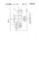
- FIG. 1is a block diagram of a node in an embodiment according to the present invention.
- FIG. 2is a network system arrangement diagram in an embodiment according to the invention.
- FIG. 3is a diagram showing an area constitution in an RAM in the embodiment
- FIG. 4is a transmission frame format diagram which is used in the embodiment.
- FIGS. 5A and 5Bare flowcharts for the media monitoring processes in a transmitting apparatus in the embodiment.
- FIG. 6is a conventional network system arrangement diagram.
- FIG. 1shows an embodiment of a transmitting apparatus connected to a network system to which the invention is applied.
- a transmission path 1 serving as a communication mediumis made of metal, optical fiber cable, or the like.
- Reference numeral 2denotes a transmission/reception node similar to the nodes 60a to 60d shown in FIG. 6.
- Reference numeral 3represents various kinds of business machines such as work station, office computer, personal computer, etc. One station is constructed by combining the node and business machines 3.
- reference numeral 4denotes a transmission interface consisting of a driver/receiver circuit for controlling the data input and output with the transmission path 1, a DMA controller, a data buffer, etc.; 5 indicates a CPU consisting of a microprocessor to perform the whole control of the node in accordance with a program shown in, e.g., FIG. 5 and stored in a ROM 7; 6 is a machine interface to execute the input/output control with the various kinds of business machines 3; 7 the ROM to store the transmission control program shown in FIG.
- a random access memory(hereinafter, referred to as a RAM) to store various information
- 9a token detector to detect the token which is sent to the transmission path 1
- 10a node address setter which consists of a dip switch and the like and sets the self node address.
- FIG. 2shows an arrangement of a network system consisting of a plurality of stations having the foregoing arrangement.
- reference numerals 2a to 2edenote nodes constituting the network and 3a to 3e represent various kinds of machines connected to the nodes 2a to 2e.
- FIG. 3is a diagram showing a part of memory areas assigned to the RAM 8.
- Aadenotes a media monitoring mode flag a which is set when the node operates in the media monitoring mode
- Abindicates an SMM instruction reception flag b which is set when a media monitoring mode setting instruction (hereinafter, referred to as an SMM instruction) to the self node is received
- Acis a token destination address c to store the destination address of the token
- Adis a collected data address pointer d indicative of the address in which the data collected in the media monitoring mode are stored
- Aeis a collected data storage area e to store the collected data.
- Start addresses of those areas in the RAM 8are set to A, B, C, D, and E.
- Zrepresents a last address in the collected data storage area e.
- FIG. 4shows an example of a transmission frame format of the data which is used in this embodiment.
- reference numeral 41denotes a frame control region (FC) into which communication control instructions such as a communication right transfer instruction (token) and the like are written; 42 is a destination address region (DA): 43 a sender address region (SA); and 44 a data region (DT) into which various kinds of data are written.
- FCframe control region
- DAdestination address region
- SAsender address region
- DTdata region
- the CPU 5 in the node 2 in FIG. 1executes the following communication control processes in accordance with the programs shown in FIGS. 5A and 5B which have previously been stored in the ROM 7.
- a checkis made to see if the transmission interface 4 has received the transmission frame from the transmission path 1 or not in step S1.
- step S2follows and the current operating mode of the node 2 is checked by reading the media monitoring mode flag a from the RAM 8.
- the media monitoring mode flag ais reset.
- the content of the collected data address pointer dassumes that the start address E in the collected data storage area e has been set.
- step S2the processing routine advances to step S3 and a check is made to see if the DA 42 of the received transmission frame coincides with the set value of the node address setter 10 or not. That is, a check is made to see if the received transmission frame is the transmission frame for the self node or not. If it is not the transmission frame for the self node and if the DA 42 does not coincide with the set value of the node address setter 10, nothing is performed but the processing routine is returned to step S1. If they coincide, this means that the transmission frame for the self node has been received, so that step S4 follows and a check is made by the token detector 9 whether the FC 41 is the token code or not.
- step S4If YES in step S4, this means that this node acquired the communication right and the reception of the token is informed to the CPU 5.
- the processing routineadvances to step S7 and a check is made to see if an SMM instruction reception flag, which will be explained hereinafter, has been set or not. Since the SMM instruction reception flag is not generally set, step S11 follows. In step S11, checks are made to see if a transmission request has been sent from the machine 3 connected to the self node and to see if the data to be transmitted exists or not. If the transmission request has been generated, step S12 follows and the normal transmission process is executed. After completion of the execution of the normal transmission process, step S10 follows.
- step S10follows and the token is sent to the downward node indicated by the token destination address c in the RAM 8 and the processing routine is returned to step S1.
- step S6follows and the SMM instruction reception flag b in the RAM 8 is set. Thereafter, the processing routine is returned to step S1 and the apparatus waits for the reception of the token to the self node.
- step S4When the token to the self node is detected in step S4 through steps S2 and S3, a check is made in step S7 to see if the SMM instruction reception flag b in the RAM 8 has been set or not.
- step S8follows and the token destination change (from the node 2b to the node 2c) is instructed to the upward node (the node 2a).
- the token destination changeis realized by the following manner. Namely, the address of the node 2a is written into the DA 42. The self node address value (node 2b) is written into the SA 43. The transmission frame in which the address of the node 2c as the downward node of the self node is sent to the DT44.
- step S9the media monitoring mode flag a in the RAM 8 is set and step S10 then follows.
- step S10the token is sent to the downward node (the node 2c) and thereafter, the processing routine is returned to step S1.
- step S13 shown in FIG. 5Bfollows step S2 because the media monitoring mode flag a has been set in this case.
- the FC 41 of the received transmission frameis checked to see if the FC 41 is a media monitoring mode cancelling instruction (hereinafter, referred to as an RMM instruction) code or not. If NO in step S13, step S14 follows and the collected data storing process from the transmission medium is then executed.
- an RMM instructionmedia monitoring mode cancelling instruction
- step S14the collected data address pointer d is read out of the RAM 8.
- step S15the address to store the collected data is set in the RAM 8.
- the collected datais stored into the collected data storage area e.
- step S16the content of the collected data address pointer d is updated by advancing its storage address to the address into which the next collected data should be stored. In this case, if the address exceeds the last address Z in the storage area e, the address is returned to the start address E.
- Parts of the FC 41, DA 42, SA 43, and DT 44, and the like of the received transmission frameare included in the content of the collected data.
- the data transmitted by the transmission pathis successively stored into the collected data storage area e irrespective of the destination address by the foregoing processes.
- the operating mode of the node 2bcan be also returned from the media monitoring mode to the normal operating mode.
- the RMM instructionis indicated to the node 2b.
- step S17follows and the media monitoring mode flag a is reset. Then, the processing routine is returned to step S1. Therefore, when the transmission frame is received after that, the normal reception process is executed since the media monitoring mode flag a has been reset.
- the network monitoring systemwhen the operating mode of the node connected to the LAN using the token passing method is changed from the normal operating mode to the media monitoring mode, the destination change of the token is instructed to the upward node. Accordingly, since the malfunction such as loss of the token does not occur, the network monitoring system with high reliability can be provided.
Landscapes
- Engineering & Computer Science (AREA)
- Computer Networks & Wireless Communication (AREA)
- Signal Processing (AREA)
- Small-Scale Networks (AREA)
- Maintenance And Management Of Digital Transmission (AREA)
Abstract
Description
Claims (5)
Applications Claiming Priority (2)
| Application Number | Priority Date | Filing Date | Title |
|---|---|---|---|
| JP62162475AJPS648745A (en) | 1987-07-01 | 1987-07-01 | Communication medium supervising system |
| JP62-162475 | 1987-07-01 |
Publications (1)
| Publication Number | Publication Date |
|---|---|
| US4891639Atrue US4891639A (en) | 1990-01-02 |
Family
ID=15755328
Family Applications (1)
| Application Number | Title | Priority Date | Filing Date |
|---|---|---|---|
| US07/210,313Expired - LifetimeUS4891639A (en) | 1987-07-01 | 1988-06-23 | Monitoring system of network |
Country Status (2)
| Country | Link |
|---|---|
| US (1) | US4891639A (en) |
| JP (1) | JPS648745A (en) |
Cited By (13)
| Publication number | Priority date | Publication date | Assignee | Title |
|---|---|---|---|---|
| US5101402A (en)* | 1988-05-24 | 1992-03-31 | Digital Equipment Corporation | Apparatus and method for realtime monitoring of network sessions in a local area network |
| US5124984A (en)* | 1990-08-07 | 1992-06-23 | Concord Communications, Inc. | Access controller for local area network |
| US5247517A (en)* | 1989-10-20 | 1993-09-21 | Novell, Inc. | Method and apparatus for analyzing networks |
| US5289458A (en)* | 1992-03-30 | 1994-02-22 | Intel Corporation | Apparatus for accomplishing autoport selection |
| US5319633A (en)* | 1992-08-17 | 1994-06-07 | International Business Machines Corporation | Enhanced serial network topology generation algorithm |
| US5392291A (en)* | 1991-05-20 | 1995-02-21 | Alliedsignal Inc. | Fault-tolerant CITO communication system |
| US5423000A (en)* | 1988-09-26 | 1995-06-06 | Hitachi, Ltd. | Operation control technique for computer system by driving a command procedure with reference to events recorded on a logging storage computer operation control by automatic decision making based on events on a logging storage |
| US5491808A (en)* | 1992-09-30 | 1996-02-13 | Conner Peripherals, Inc. | Method for tracking memory allocation in network file server |
| US20030048356A1 (en)* | 1998-07-24 | 2003-03-13 | Akihiro Kohno | Communication apparatus and method, and storage medium |
| US6651099B1 (en) | 1999-06-30 | 2003-11-18 | Hi/Fn, Inc. | Method and apparatus for monitoring traffic in a network |
| US6771646B1 (en) | 1999-06-30 | 2004-08-03 | Hi/Fn, Inc. | Associative cache structure for lookups and updates of flow records in a network monitor |
| US6789116B1 (en) | 1999-06-30 | 2004-09-07 | Hi/Fn, Inc. | State processor for pattern matching in a network monitor device |
| CN115097772A (en)* | 2022-06-17 | 2022-09-23 | 南京国电南自轨道交通工程有限公司 | A method for handover of BAS authority of integrated monitoring system |
Families Citing this family (1)
| Publication number | Priority date | Publication date | Assignee | Title |
|---|---|---|---|---|
| JP2008205329A (en)* | 2007-02-22 | 2008-09-04 | Nichia Chem Ind Ltd | Semiconductor device |
Citations (7)
| Publication number | Priority date | Publication date | Assignee | Title |
|---|---|---|---|---|
| US4304001A (en)* | 1980-01-24 | 1981-12-01 | Forney Engineering Company | Industrial control system with interconnected remotely located computer control units |
| US4495493A (en)* | 1981-04-15 | 1985-01-22 | U.S. Philips Corporation | Method of controlling the transmission/reception of data in a local communication network, and data transmission system for performing the method |
| US4527270A (en)* | 1983-05-04 | 1985-07-02 | Allen-Bradley Company | Communications network with stations that detect and automatically bypass faults |
| US4583089A (en)* | 1983-04-19 | 1986-04-15 | Foster Wheeler Energy Corporation | Distributed computer control system with variable monitor timers |
| US4649535A (en)* | 1985-05-13 | 1987-03-10 | General Electric Company | Method and apparatus for maintaining a dynamic logical ring in a token passing LAN |
| US4680581A (en)* | 1985-03-28 | 1987-07-14 | Honeywell Inc. | Local area network special function frames |
| US4701910A (en)* | 1985-11-29 | 1987-10-20 | General Electric Company | Reliable local area network including active stations |
- 1987
- 1987-07-01JPJP62162475Apatent/JPS648745A/enactivePending
- 1988
- 1988-06-23USUS07/210,313patent/US4891639A/ennot_activeExpired - Lifetime
Patent Citations (7)
| Publication number | Priority date | Publication date | Assignee | Title |
|---|---|---|---|---|
| US4304001A (en)* | 1980-01-24 | 1981-12-01 | Forney Engineering Company | Industrial control system with interconnected remotely located computer control units |
| US4495493A (en)* | 1981-04-15 | 1985-01-22 | U.S. Philips Corporation | Method of controlling the transmission/reception of data in a local communication network, and data transmission system for performing the method |
| US4583089A (en)* | 1983-04-19 | 1986-04-15 | Foster Wheeler Energy Corporation | Distributed computer control system with variable monitor timers |
| US4527270A (en)* | 1983-05-04 | 1985-07-02 | Allen-Bradley Company | Communications network with stations that detect and automatically bypass faults |
| US4680581A (en)* | 1985-03-28 | 1987-07-14 | Honeywell Inc. | Local area network special function frames |
| US4649535A (en)* | 1985-05-13 | 1987-03-10 | General Electric Company | Method and apparatus for maintaining a dynamic logical ring in a token passing LAN |
| US4701910A (en)* | 1985-11-29 | 1987-10-20 | General Electric Company | Reliable local area network including active stations |
Cited By (20)
| Publication number | Priority date | Publication date | Assignee | Title |
|---|---|---|---|---|
| US5101402A (en)* | 1988-05-24 | 1992-03-31 | Digital Equipment Corporation | Apparatus and method for realtime monitoring of network sessions in a local area network |
| US5423000A (en)* | 1988-09-26 | 1995-06-06 | Hitachi, Ltd. | Operation control technique for computer system by driving a command procedure with reference to events recorded on a logging storage computer operation control by automatic decision making based on events on a logging storage |
| US5247517A (en)* | 1989-10-20 | 1993-09-21 | Novell, Inc. | Method and apparatus for analyzing networks |
| US5124984A (en)* | 1990-08-07 | 1992-06-23 | Concord Communications, Inc. | Access controller for local area network |
| US5392291A (en)* | 1991-05-20 | 1995-02-21 | Alliedsignal Inc. | Fault-tolerant CITO communication system |
| US5289458A (en)* | 1992-03-30 | 1994-02-22 | Intel Corporation | Apparatus for accomplishing autoport selection |
| GB2265797B (en)* | 1992-03-30 | 1995-11-01 | Intel Corp | Apparatus for accomplishing autoport selection |
| US5319633A (en)* | 1992-08-17 | 1994-06-07 | International Business Machines Corporation | Enhanced serial network topology generation algorithm |
| US5491808A (en)* | 1992-09-30 | 1996-02-13 | Conner Peripherals, Inc. | Method for tracking memory allocation in network file server |
| US7262791B2 (en) | 1998-07-24 | 2007-08-28 | Canon Kabushiki Kaisha | Communication apparatus and method, and storage medium |
| US20030048356A1 (en)* | 1998-07-24 | 2003-03-13 | Akihiro Kohno | Communication apparatus and method, and storage medium |
| US6651099B1 (en) | 1999-06-30 | 2003-11-18 | Hi/Fn, Inc. | Method and apparatus for monitoring traffic in a network |
| US20040083299A1 (en)* | 1999-06-30 | 2004-04-29 | Dietz Russell S. | Method and apparatus for monitoring traffic in a network |
| US6771646B1 (en) | 1999-06-30 | 2004-08-03 | Hi/Fn, Inc. | Associative cache structure for lookups and updates of flow records in a network monitor |
| US6789116B1 (en) | 1999-06-30 | 2004-09-07 | Hi/Fn, Inc. | State processor for pattern matching in a network monitor device |
| US20040199630A1 (en)* | 1999-06-30 | 2004-10-07 | Sarkissian Haig A. | State processor for pattern matching in a network monitor device |
| US6954789B2 (en) | 1999-06-30 | 2005-10-11 | Hi/Fn, Inc. | Method and apparatus for monitoring traffic in a network |
| US6665725B1 (en) | 1999-06-30 | 2003-12-16 | Hi/Fn, Inc. | Processing protocol specific information in packets specified by a protocol description language |
| US7299282B2 (en) | 1999-06-30 | 2007-11-20 | Hi/Fn Inc. | State processor for pattern matching in a network monitor device |
| CN115097772A (en)* | 2022-06-17 | 2022-09-23 | 南京国电南自轨道交通工程有限公司 | A method for handover of BAS authority of integrated monitoring system |
Also Published As
| Publication number | Publication date |
|---|---|
| JPS648745A (en) | 1989-01-12 |
Similar Documents
| Publication | Publication Date | Title |
|---|---|---|
| US4891639A (en) | Monitoring system of network | |
| US7016957B2 (en) | Distributed data processing system and error analysis information saving method appropriate therefor | |
| US5517488A (en) | Method of load distribution for message processing in host system in local area network | |
| US4825204A (en) | Address setting and data transmission system | |
| US4701908A (en) | Network system utilizing plural station addresses | |
| US5450567A (en) | Method and system for program change in distributed data processing system | |
| US4416008A (en) | Dual loop type data highway system | |
| CN108966281B (en) | Mesh network processing method, device, equipment and storage medium | |
| JPH03204258A (en) | Fault detection system, transmission line reconstitution system and communication system | |
| JPS6251016B2 (en) | ||
| US5968187A (en) | Computer system and method including a portable portion that has a capability to diagnose and perform analysis for a stationary position and for a portable portion | |
| JP2972601B2 (en) | Wireless communication adapter device | |
| JP2811770B2 (en) | Host computer device | |
| US5724029A (en) | Communication interconnection device with processing interrupt based on token address | |
| US6771656B1 (en) | Communication right determination method, information processing apparatus use therefor, and computer-readable recording medium recorded with program for carrying out the method | |
| KR0182695B1 (en) | How to Operate Host Exchange and Remote Switching Period | |
| KR0136952B1 (en) | Method of exchanging the data between a client and a server | |
| JP2000293454A (en) | Data communication device, data communication method, and recording medium | |
| KR100678098B1 (en) | Memory access method of transmission equipment | |
| KR0174001B1 (en) | Path selector of high level data link control procedure frame | |
| JP2626224B2 (en) | Host computer | |
| JP2003174460A (en) | Data communication method, its execution system, and its processing program | |
| JPH10229590A (en) | Network communication method | |
| JPS6194163A (en) | Remote ipl control system | |
| JPH05308369A (en) | Control station determination method for loop communication system |
Legal Events
| Date | Code | Title | Description |
|---|---|---|---|
| AS | Assignment | Owner name:CANON KABUSHIKI KAISHA, 30-2, 3-CHOME, SHIMOMARUKO Free format text:ASSIGNMENT OF ASSIGNORS INTEREST.;ASSIGNOR:NAKAMURA, YASUO;REEL/FRAME:004923/0446 Effective date:19880620 Owner name:CANON KABUSHIKI KAISHA, A CORP. OF JAPAN,JAPAN Free format text:ASSIGNMENT OF ASSIGNORS INTEREST;ASSIGNOR:NAKAMURA, YASUO;REEL/FRAME:004923/0446 Effective date:19880620 | |
| STCF | Information on status: patent grant | Free format text:PATENTED CASE | |
| CC | Certificate of correction | ||
| FEPP | Fee payment procedure | Free format text:PAYOR NUMBER ASSIGNED (ORIGINAL EVENT CODE: ASPN); ENTITY STATUS OF PATENT OWNER: LARGE ENTITY | |
| FPAY | Fee payment | Year of fee payment:4 | |
| FPAY | Fee payment | Year of fee payment:8 | |
| FEPP | Fee payment procedure | Free format text:PAYOR NUMBER ASSIGNED (ORIGINAL EVENT CODE: ASPN); ENTITY STATUS OF PATENT OWNER: LARGE ENTITY | |
| FEPP | Fee payment procedure | Free format text:PAYER NUMBER DE-ASSIGNED (ORIGINAL EVENT CODE: RMPN); ENTITY STATUS OF PATENT OWNER: LARGE ENTITY | |
| FPAY | Fee payment | Year of fee payment:12 |