US4890089A - Distribution of line carrier communications - Google Patents
Distribution of line carrier communicationsDownload PDFInfo
- Publication number
- US4890089A US4890089AUS07/275,843US27584388AUS4890089AUS 4890089 AUS4890089 AUS 4890089AUS 27584388 AUS27584388 AUS 27584388AUS 4890089 AUS4890089 AUS 4890089A
- Authority
- US
- United States
- Prior art keywords
- distribution system
- frequency
- communications
- power
- signal
- Prior art date
- Legal status (The legal status is an assumption and is not a legal conclusion. Google has not performed a legal analysis and makes no representation as to the accuracy of the status listed.)
- Expired - Fee Related
Links
Images
Classifications
- H—ELECTRICITY
- H04—ELECTRIC COMMUNICATION TECHNIQUE
- H04B—TRANSMISSION
- H04B3/00—Line transmission systems
- H04B3/54—Systems for transmission via power distribution lines
- H04B3/56—Circuits for coupling, blocking, or by-passing of signals
- H—ELECTRICITY
- H04—ELECTRIC COMMUNICATION TECHNIQUE
- H04B—TRANSMISSION
- H04B2203/00—Indexing scheme relating to line transmission systems
- H04B2203/54—Aspects of powerline communications not already covered by H04B3/54 and its subgroups
- H04B2203/5429—Applications for powerline communications
- H04B2203/545—Audio/video application, e.g. interphone
- H—ELECTRICITY
- H04—ELECTRIC COMMUNICATION TECHNIQUE
- H04B—TRANSMISSION
- H04B2203/00—Indexing scheme relating to line transmission systems
- H04B2203/54—Aspects of powerline communications not already covered by H04B3/54 and its subgroups
- H04B2203/5462—Systems for power line communications
- H04B2203/5479—Systems for power line communications using repeaters
- H—ELECTRICITY
- H04—ELECTRIC COMMUNICATION TECHNIQUE
- H04B—TRANSMISSION
- H04B2203/00—Indexing scheme relating to line transmission systems
- H04B2203/54—Aspects of powerline communications not already covered by H04B3/54 and its subgroups
- H04B2203/5462—Systems for power line communications
- H04B2203/5483—Systems for power line communications using coupling circuits
- H—ELECTRICITY
- H04—ELECTRIC COMMUNICATION TECHNIQUE
- H04B—TRANSMISSION
- H04B2203/00—Indexing scheme relating to line transmission systems
- H04B2203/54—Aspects of powerline communications not already covered by H04B3/54 and its subgroups
- H04B2203/5462—Systems for power line communications
- H04B2203/5491—Systems for power line communications using filtering and bypassing
Definitions
- the present inventionrelates to systems for use in distribution line carrier communications in which communication signals are transmitted over high voltage power transmission lines.
- Communications transmissions of this typerequire repeaters disposed at spaced intervals along such high voltage power transmission lines. These repeaters must be connected to the transmission lines via couplings which have a low impedance at the communication signal carrier frequencies.
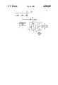
- the sole FIGUREis a circuit diagram illustrating the coupling of a communications signal repeater to high voltage power distribution lines according to a preferred embodiment of the present invention.
- the FIGUREshows three lines 2 of a high voltage power distribution path for tansmitting power at the conventional frequency of 60 Hz and communications signals which may, for example, be digital signals in the audio frequency range of 7-15 KHz.
- Lines 2are connected to a fixed power factor capacitor bank composed of capacitors 4 connected in a wye configuration and having capacitance values selected, on the basis of principles known in the art, to account for the baseline loading and inherent reactance of the power distribution system. If the common connection point of capacitors 4 were directly connected to ground, the capacitors would present nearly a short circuit to ground with respect to audio frequency communications signals and would therefore significantly reduce the communications signal voltages at points along the distribution path downstream of the capacitor bank.
- Capacitor blocking unit 6increases the impedance between the common connection point of capacitors 4 and ground with respect to audio frequency signals.
- a capacitor blocking unit 6 of the type identified abovehas an impedance characteristic which varies proportionally with frequency and which can maintain the 60 Hz voltage at the common connection point between capacitors 4 at a fixed value which is typically less than 50 volts RMS. Since, however, unit 6 offers a high impedance to higher frequency signals, only a negligible portion of the energy content of those signals will be dissipated in that unit.
- connection point between capacitors 4 and unit 6is connected via a coupling capacitor 10 and a signal coupling unit 12 to a communication signal repeater 14 which functions, in a manner known in the art, to boost the level of any communications signal on lines 2.
- Coupling capacitor 10could, by way of example, have a capacitance of the order of 1 ⁇ F.
- Communications signals conducted via capacitor 10are conducted to unit 12, where they are applied across a drain coil 16 and the primary 18 of a transformer, primary 18 being connected across coil 16 via a coupling capacitor 20 which provides additional 60 Hz isolation.
- the secondary 22 of the transformeris provided with a plurality of spaced taps and the terminals of repeater 14 are connected between one end of secondary 22 and a tap selected to provide a good impedance match between repeater 14 and unit 12 with respect to communications signals.
- the signals arriving at repeater 14are boosted in strength and returned, via the same path, to transmission lines 2.
- Signal coupling unit 12could be constituted by a commercially available device, such as a Model 821 Signal Coupling Unit marketed by the Westinghouse Electric Corporation. However, coil 16 can be selected to have a reduced current rating because of the presence of capacitor 10.
- Repeater 14could equally be a commercially available device such as an RPT 900 Series device marketed by the Westinghouse Electric Corporation.
Landscapes
- Engineering & Computer Science (AREA)
- Power Engineering (AREA)
- Computer Networks & Wireless Communication (AREA)
- Signal Processing (AREA)
- Cable Transmission Systems, Equalization Of Radio And Reduction Of Echo (AREA)
Abstract
Description
Claims (6)
Priority Applications (1)
| Application Number | Priority Date | Filing Date | Title |
|---|---|---|---|
| US07/275,843US4890089A (en) | 1988-11-25 | 1988-11-25 | Distribution of line carrier communications |
Applications Claiming Priority (1)
| Application Number | Priority Date | Filing Date | Title |
|---|---|---|---|
| US07/275,843US4890089A (en) | 1988-11-25 | 1988-11-25 | Distribution of line carrier communications |
Publications (1)
| Publication Number | Publication Date |
|---|---|
| US4890089Atrue US4890089A (en) | 1989-12-26 |
Family
ID=23054037
Family Applications (1)
| Application Number | Title | Priority Date | Filing Date |
|---|---|---|---|
| US07/275,843Expired - Fee RelatedUS4890089A (en) | 1988-11-25 | 1988-11-25 | Distribution of line carrier communications |
Country Status (1)
| Country | Link |
|---|---|
| US (1) | US4890089A (en) |
Cited By (44)
| Publication number | Priority date | Publication date | Assignee | Title |
|---|---|---|---|---|
| US5406249A (en)* | 1993-03-09 | 1995-04-11 | Metricom, Inc. | Method and structure for coupling power-line carrier current signals using common-mode coupling |
| US5694108A (en)* | 1996-05-01 | 1997-12-02 | Abb Power T&D Company Inc. | Apparatus and methods for power network coupling |
| US5818821A (en) | 1994-12-30 | 1998-10-06 | Intelogis, Inc. | Universal lan power line carrier repeater system and method |
| US5933073A (en)* | 1997-07-07 | 1999-08-03 | Abb Power T&D Company Inc. | Apparatus and methods for power network coupling |
| EP0877494A3 (en)* | 1997-05-08 | 1999-09-08 | AT&T Corp. | Active ground compensation for power line communication |
| US5970127A (en) | 1997-10-16 | 1999-10-19 | Phonex Corporation | Caller identification system for wireless phone jacks and wireless modem jacks |
| US5978371A (en)* | 1997-03-31 | 1999-11-02 | Abb Power T&D Company Inc. | Communications module base repeater |
| US6055435A (en) | 1997-10-16 | 2000-04-25 | Phonex Corporation | Wireless telephone connection surge suppressor |
| US6107912A (en) | 1997-12-08 | 2000-08-22 | Phonex Corporation | Wireless modem jack |
| DE19944919A1 (en)* | 1999-09-20 | 2001-03-22 | Abb Research Ltd | Communication in aerial ropeway having mechanically supportive- and tractive cables, employs electromagnetic signal coupling into either cable |
| US6243571B1 (en) | 1998-09-21 | 2001-06-05 | Phonex Corporation | Method and system for distribution of wireless signals for increased wireless coverage using power lines |
| US6246868B1 (en) | 1998-08-14 | 2001-06-12 | Phonex Corporation | Conversion and distribution of incoming wireless telephone signals using the power line |
| US20010045888A1 (en)* | 2000-01-20 | 2001-11-29 | Kline Paul A. | Method of isolating data in a power line communications network |
| US20020154000A1 (en)* | 2001-02-14 | 2002-10-24 | Kline Paul A. | Data communication over a power line |
| WO2004008656A1 (en)* | 2002-07-16 | 2004-01-22 | Power Plus Communications Ag | System for carrying out the line transmission of data over an electric network |
| US6856647B1 (en) | 2000-10-17 | 2005-02-15 | General Electric Company | Methods and systems for neutral-to-ground communication |
| US6950567B2 (en) | 2001-02-14 | 2005-09-27 | Current Technologies, Llc | Method and apparatus for providing inductive coupling and decoupling of high-frequency, high-bandwidth data signals directly on and off of a high voltage power line |
| US6958680B2 (en) | 2000-04-14 | 2005-10-25 | Current Technologies, Llc | Power line communication system and method of using the same |
| US6965303B2 (en) | 2002-12-10 | 2005-11-15 | Current Technologies, Llc | Power line communication system and method |
| US6965302B2 (en) | 2000-04-14 | 2005-11-15 | Current Technologies, Llc | Power line communication system and method of using the same |
| US6980090B2 (en) | 2002-12-10 | 2005-12-27 | Current Technologies, Llc | Device and method for coupling with electrical distribution network infrastructure to provide communications |
| US6980091B2 (en) | 2002-12-10 | 2005-12-27 | Current Technologies, Llc | Power line communication system and method of operating the same |
| US6980089B1 (en) | 2000-08-09 | 2005-12-27 | Current Technologies, Llc | Non-intrusive coupling to shielded power cable |
| US6982611B2 (en) | 2002-06-24 | 2006-01-03 | Current Technologies, Llc | Power line coupling device and method of using the same |
| US6998962B2 (en) | 2000-04-14 | 2006-02-14 | Current Technologies, Llc | Power line communication apparatus and method of using the same |
| US7046124B2 (en) | 2003-01-21 | 2006-05-16 | Current Technologies, Llc | Power line coupling device and method of using the same |
| US7053756B2 (en) | 2001-12-21 | 2006-05-30 | Current Technologies, Llc | Facilitating communication of data signals on electric power systems |
| US7064654B2 (en) | 2002-12-10 | 2006-06-20 | Current Technologies, Llc | Power line communication system and method of operating the same |
| US7069091B2 (en) | 2001-11-01 | 2006-06-27 | Salton, Inc. | Intelligent microwave oven appliance |
| US7075414B2 (en) | 2003-05-13 | 2006-07-11 | Current Technologies, Llc | Device and method for communicating data signals through multiple power line conductors |
| US7102478B2 (en) | 2002-06-21 | 2006-09-05 | Current Technologies, Llc | Power line coupling device and method of using the same |
| US7132819B1 (en) | 2002-11-12 | 2006-11-07 | Current Technologies, Llc | Floating power supply and method of using the same |
| US7151968B2 (en) | 2001-11-01 | 2006-12-19 | Salton, Inc. | Intelligent coffeemaker appliance |
| US7245472B2 (en) | 2001-05-18 | 2007-07-17 | Curretn Grid, Llc | Medium voltage signal coupling structure for last leg power grid high-speed data network |
| US7245201B1 (en) | 2000-08-09 | 2007-07-17 | Current Technologies, Llc | Power line coupling device and method of using the same |
| US7248148B2 (en) | 2000-08-09 | 2007-07-24 | Current Technologies, Llc | Power line coupling device and method of using the same |
| US7307512B2 (en) | 2005-04-29 | 2007-12-11 | Current Technologies, Llc | Power line coupling device and method of use |
| US7424031B2 (en) | 1998-07-28 | 2008-09-09 | Serconet, Ltd. | Local area network of serial intelligent cells |
| US7656904B2 (en) | 2003-03-13 | 2010-02-02 | Mosaid Technologies Incorporated | Telephone system having multiple distinct sources and accessories therefor |
| US7795994B2 (en) | 2007-06-26 | 2010-09-14 | Current Technologies, Llc | Power line coupling device and method |
| US7876767B2 (en) | 2000-04-19 | 2011-01-25 | Mosaid Technologies Incorporated | Network combining wired and non-wired segments |
| US7876174B2 (en) | 2007-06-26 | 2011-01-25 | Current Technologies, Llc | Power line coupling device and method |
| US20110101783A1 (en)* | 2008-07-28 | 2011-05-05 | Eveready Battery Company, Inc. | Electrical Power Distribution System and Method Thereof |
| US9793873B2 (en) | 2011-06-30 | 2017-10-17 | Silicon Laboratories Inc. | Circuits and methods for providing an impedance adjustment |
Citations (6)
| Publication number | Priority date | Publication date | Assignee | Title |
|---|---|---|---|---|
| US4408186A (en)* | 1981-02-04 | 1983-10-04 | General Electric Co. | Power line communication over ground and neutral conductors of plural residential branch circuits |
| US4442364A (en)* | 1981-07-21 | 1984-04-10 | Bicc Public Limited Company | Overhead electric transmission systems |
| US4556864A (en)* | 1982-08-26 | 1985-12-03 | Roy Joseph J | Apparatus and method for communicating digital information on AC power lines |
| US4636771A (en)* | 1984-12-10 | 1987-01-13 | Westinghouse Electric Corp. | Power line communications terminal and interface circuit associated therewith |
| US4668934A (en)* | 1984-10-22 | 1987-05-26 | Westinghouse Electric Corp. | Receiver apparatus for three-phase power line carrier communications |
| US4766414A (en)* | 1986-06-17 | 1988-08-23 | Westinghouse Electric Corp. | Power line communication interference preventing circuit |
- 1988
- 1988-11-25USUS07/275,843patent/US4890089A/ennot_activeExpired - Fee Related
Patent Citations (6)
| Publication number | Priority date | Publication date | Assignee | Title |
|---|---|---|---|---|
| US4408186A (en)* | 1981-02-04 | 1983-10-04 | General Electric Co. | Power line communication over ground and neutral conductors of plural residential branch circuits |
| US4442364A (en)* | 1981-07-21 | 1984-04-10 | Bicc Public Limited Company | Overhead electric transmission systems |
| US4556864A (en)* | 1982-08-26 | 1985-12-03 | Roy Joseph J | Apparatus and method for communicating digital information on AC power lines |
| US4668934A (en)* | 1984-10-22 | 1987-05-26 | Westinghouse Electric Corp. | Receiver apparatus for three-phase power line carrier communications |
| US4636771A (en)* | 1984-12-10 | 1987-01-13 | Westinghouse Electric Corp. | Power line communications terminal and interface circuit associated therewith |
| US4766414A (en)* | 1986-06-17 | 1988-08-23 | Westinghouse Electric Corp. | Power line communication interference preventing circuit |
Cited By (69)
| Publication number | Priority date | Publication date | Assignee | Title |
|---|---|---|---|---|
| US5406249A (en)* | 1993-03-09 | 1995-04-11 | Metricom, Inc. | Method and structure for coupling power-line carrier current signals using common-mode coupling |
| US5818821A (en) | 1994-12-30 | 1998-10-06 | Intelogis, Inc. | Universal lan power line carrier repeater system and method |
| US5694108A (en)* | 1996-05-01 | 1997-12-02 | Abb Power T&D Company Inc. | Apparatus and methods for power network coupling |
| US5978371A (en)* | 1997-03-31 | 1999-11-02 | Abb Power T&D Company Inc. | Communications module base repeater |
| EP0877494A3 (en)* | 1997-05-08 | 1999-09-08 | AT&T Corp. | Active ground compensation for power line communication |
| US5933073A (en)* | 1997-07-07 | 1999-08-03 | Abb Power T&D Company Inc. | Apparatus and methods for power network coupling |
| US5970127A (en) | 1997-10-16 | 1999-10-19 | Phonex Corporation | Caller identification system for wireless phone jacks and wireless modem jacks |
| US6055435A (en) | 1997-10-16 | 2000-04-25 | Phonex Corporation | Wireless telephone connection surge suppressor |
| US6107912A (en) | 1997-12-08 | 2000-08-22 | Phonex Corporation | Wireless modem jack |
| US7852874B2 (en) | 1998-07-28 | 2010-12-14 | Mosaid Technologies Incorporated | Local area network of serial intelligent cells |
| US7424031B2 (en) | 1998-07-28 | 2008-09-09 | Serconet, Ltd. | Local area network of serial intelligent cells |
| US7978726B2 (en) | 1998-07-28 | 2011-07-12 | Mosaid Technologies Incorporated | Local area network of serial intelligent cells |
| US8867523B2 (en) | 1998-07-28 | 2014-10-21 | Conversant Intellectual Property Management Incorporated | Local area network of serial intelligent cells |
| US8885660B2 (en) | 1998-07-28 | 2014-11-11 | Conversant Intellectual Property Management Incorporated | Local area network of serial intelligent cells |
| US8885659B2 (en) | 1998-07-28 | 2014-11-11 | Conversant Intellectual Property Management Incorporated | Local area network of serial intelligent cells |
| US8908673B2 (en) | 1998-07-28 | 2014-12-09 | Conversant Intellectual Property Management Incorporated | Local area network of serial intelligent cells |
| US6246868B1 (en) | 1998-08-14 | 2001-06-12 | Phonex Corporation | Conversion and distribution of incoming wireless telephone signals using the power line |
| US6243571B1 (en) | 1998-09-21 | 2001-06-05 | Phonex Corporation | Method and system for distribution of wireless signals for increased wireless coverage using power lines |
| DE19944919A1 (en)* | 1999-09-20 | 2001-03-22 | Abb Research Ltd | Communication in aerial ropeway having mechanically supportive- and tractive cables, employs electromagnetic signal coupling into either cable |
| US6977578B2 (en) | 2000-01-20 | 2005-12-20 | Current Technologies, Llc | Method of isolating data in a power line communications network |
| US20010045888A1 (en)* | 2000-01-20 | 2001-11-29 | Kline Paul A. | Method of isolating data in a power line communications network |
| US6965302B2 (en) | 2000-04-14 | 2005-11-15 | Current Technologies, Llc | Power line communication system and method of using the same |
| US6958680B2 (en) | 2000-04-14 | 2005-10-25 | Current Technologies, Llc | Power line communication system and method of using the same |
| US7245212B2 (en) | 2000-04-14 | 2007-07-17 | Current Technologies, Llc | Power line communication apparatus and method of using the same |
| US6998962B2 (en) | 2000-04-14 | 2006-02-14 | Current Technologies, Llc | Power line communication apparatus and method of using the same |
| US7307511B2 (en) | 2000-04-14 | 2007-12-11 | Current Technologies, Llc | Power line communication system and method |
| US7876767B2 (en) | 2000-04-19 | 2011-01-25 | Mosaid Technologies Incorporated | Network combining wired and non-wired segments |
| US8873586B2 (en) | 2000-04-19 | 2014-10-28 | Conversant Intellectual Property Management Incorporated | Network combining wired and non-wired segments |
| US7933297B2 (en) | 2000-04-19 | 2011-04-26 | Mosaid Technologies Incorporated | Network combining wired and non-wired segments |
| US8848725B2 (en) | 2000-04-19 | 2014-09-30 | Conversant Intellectual Property Management Incorporated | Network combining wired and non-wired segments |
| US8867506B2 (en) | 2000-04-19 | 2014-10-21 | Conversant Intellectual Property Management Incorporated | Network combining wired and non-wired segments |
| US8982904B2 (en) | 2000-04-19 | 2015-03-17 | Conversant Intellectual Property Management Inc. | Network combining wired and non-wired segments |
| US6980089B1 (en) | 2000-08-09 | 2005-12-27 | Current Technologies, Llc | Non-intrusive coupling to shielded power cable |
| US7245201B1 (en) | 2000-08-09 | 2007-07-17 | Current Technologies, Llc | Power line coupling device and method of using the same |
| US7248148B2 (en) | 2000-08-09 | 2007-07-24 | Current Technologies, Llc | Power line coupling device and method of using the same |
| US6856647B1 (en) | 2000-10-17 | 2005-02-15 | General Electric Company | Methods and systems for neutral-to-ground communication |
| US7103240B2 (en) | 2001-02-14 | 2006-09-05 | Current Technologies, Llc | Method and apparatus for providing inductive coupling and decoupling of high-frequency, high-bandwidth data signals directly on and off of a high voltage power line |
| US7218219B2 (en) | 2001-02-14 | 2007-05-15 | Current Technologies, Llc | Data communication over a power line |
| US7042351B2 (en) | 2001-02-14 | 2006-05-09 | Current Technologies, Llc | Data communication over a power line |
| US7453352B2 (en) | 2001-02-14 | 2008-11-18 | Current Technologies, Llc | Data communication over a power line |
| US6950567B2 (en) | 2001-02-14 | 2005-09-27 | Current Technologies, Llc | Method and apparatus for providing inductive coupling and decoupling of high-frequency, high-bandwidth data signals directly on and off of a high voltage power line |
| US6933835B2 (en) | 2001-02-14 | 2005-08-23 | Current Technologies, Llc | Data communication over a power line |
| US7414518B2 (en) | 2001-02-14 | 2008-08-19 | Current Technologies, Llc | Power line communication device and method |
| US20020154000A1 (en)* | 2001-02-14 | 2002-10-24 | Kline Paul A. | Data communication over a power line |
| US7245472B2 (en) | 2001-05-18 | 2007-07-17 | Curretn Grid, Llc | Medium voltage signal coupling structure for last leg power grid high-speed data network |
| US7773361B2 (en) | 2001-05-18 | 2010-08-10 | Current Grid, Llc | Medium voltage signal coupling structure for last leg power grid high-speed data network |
| US7151968B2 (en) | 2001-11-01 | 2006-12-19 | Salton, Inc. | Intelligent coffeemaker appliance |
| US7069091B2 (en) | 2001-11-01 | 2006-06-27 | Salton, Inc. | Intelligent microwave oven appliance |
| US7053756B2 (en) | 2001-12-21 | 2006-05-30 | Current Technologies, Llc | Facilitating communication of data signals on electric power systems |
| US7102478B2 (en) | 2002-06-21 | 2006-09-05 | Current Technologies, Llc | Power line coupling device and method of using the same |
| US7224243B2 (en) | 2002-06-24 | 2007-05-29 | Current Technologies, Llc | Power line coupling device and method of using the same |
| US6982611B2 (en) | 2002-06-24 | 2006-01-03 | Current Technologies, Llc | Power line coupling device and method of using the same |
| WO2004008656A1 (en)* | 2002-07-16 | 2004-01-22 | Power Plus Communications Ag | System for carrying out the line transmission of data over an electric network |
| US7132819B1 (en) | 2002-11-12 | 2006-11-07 | Current Technologies, Llc | Floating power supply and method of using the same |
| US7064654B2 (en) | 2002-12-10 | 2006-06-20 | Current Technologies, Llc | Power line communication system and method of operating the same |
| US7701325B2 (en) | 2002-12-10 | 2010-04-20 | Current Technologies, Llc | Power line communication apparatus and method of using the same |
| US6965303B2 (en) | 2002-12-10 | 2005-11-15 | Current Technologies, Llc | Power line communication system and method |
| US7301440B2 (en) | 2002-12-10 | 2007-11-27 | Current Technologies, Llc | Power line communication system and method |
| US7250848B2 (en) | 2002-12-10 | 2007-07-31 | Current Technologies, Llc | Power line communication apparatus and method of using the same |
| US6980090B2 (en) | 2002-12-10 | 2005-12-27 | Current Technologies, Llc | Device and method for coupling with electrical distribution network infrastructure to provide communications |
| US6980091B2 (en) | 2002-12-10 | 2005-12-27 | Current Technologies, Llc | Power line communication system and method of operating the same |
| US7046124B2 (en) | 2003-01-21 | 2006-05-16 | Current Technologies, Llc | Power line coupling device and method of using the same |
| US7656904B2 (en) | 2003-03-13 | 2010-02-02 | Mosaid Technologies Incorporated | Telephone system having multiple distinct sources and accessories therefor |
| US7075414B2 (en) | 2003-05-13 | 2006-07-11 | Current Technologies, Llc | Device and method for communicating data signals through multiple power line conductors |
| US7307512B2 (en) | 2005-04-29 | 2007-12-11 | Current Technologies, Llc | Power line coupling device and method of use |
| US7876174B2 (en) | 2007-06-26 | 2011-01-25 | Current Technologies, Llc | Power line coupling device and method |
| US7795994B2 (en) | 2007-06-26 | 2010-09-14 | Current Technologies, Llc | Power line coupling device and method |
| US20110101783A1 (en)* | 2008-07-28 | 2011-05-05 | Eveready Battery Company, Inc. | Electrical Power Distribution System and Method Thereof |
| US9793873B2 (en) | 2011-06-30 | 2017-10-17 | Silicon Laboratories Inc. | Circuits and methods for providing an impedance adjustment |
Similar Documents
| Publication | Publication Date | Title |
|---|---|---|
| US4890089A (en) | Distribution of line carrier communications | |
| US4602240A (en) | Apparatus for and method of attenuating power line carrier communication signals passing between substation distribution lines and transmission lines through substation transformers | |
| US4012733A (en) | Distribution power line communication system including a messenger wire communications link | |
| US4473816A (en) | Communications signal bypass around power line transformer | |
| US4433284A (en) | Power line communications bypass around delta-wye transformer | |
| US4004110A (en) | Power supply for power line carrier communication systems | |
| US4254402A (en) | Transformer arrangement for coupling a communication signal to a three-phase power line | |
| US3747028A (en) | Directional tap comprising pi-section high pass filter for use in catv system | |
| US9419438B2 (en) | Power-line communication coupling | |
| US4142178A (en) | High voltage signal coupler for a distribution network power line carrier communication system | |
| US5929750A (en) | Transmission network and filter therefor | |
| US4188619A (en) | Transformer arrangement for coupling a communication signal to a three-phase power line | |
| US5058198A (en) | Radio frequency tap unit which can be reconfigured with minimal disruption of service | |
| US5781386A (en) | Low level ground conditioning (gcl) | |
| US4065763A (en) | Distribution network power line communication system | |
| CA2001166C (en) | Bus coupler | |
| GB2094595A (en) | Power line communication system using the neutral and ground conductors of a residental branch circuit | |
| HU217753B (en) | Network system and method for connecting communication terminals in different rooms | |
| JPH07183836A (en) | Coupling filter device for distribution line carrier communication | |
| US7199699B1 (en) | Facilitating communication with power line communication devices | |
| US4087701A (en) | Transformer cascade for powering electronics on high voltage transmission lines | |
| EP0124260A2 (en) | Power supply line carrier communication systems | |
| US4066912A (en) | Coupling arrangement for power line carrier systems | |
| US6278266B1 (en) | Symmetrical power generator and method of use | |
| US4170761A (en) | Remotely powered intermediate amplifier for communications transmission |
Legal Events
| Date | Code | Title | Description |
|---|---|---|---|
| AS | Assignment | Owner name:WESTINGHOUSE ELECTRIC CORPORATION, A CORP. OF PA, Free format text:ASSIGNMENT OF ASSIGNORS INTEREST.;ASSIGNOR:SHUEY, KENNETH C.;REEL/FRAME:005019/0426 Effective date:19881107 | |
| AS | Assignment | Owner name:ABB POWER T&D COMPANY, INC., A DE CORP., PENNSYLV Free format text:ASSIGNMENT OF ASSIGNORS INTEREST.;ASSIGNOR:WESTINGHOUSE ELECTRIC CORPORATION, A CORP. OF PA.;REEL/FRAME:005368/0692 Effective date:19891229 | |
| FEPP | Fee payment procedure | Free format text:PAYOR NUMBER ASSIGNED (ORIGINAL EVENT CODE: ASPN); ENTITY STATUS OF PATENT OWNER: LARGE ENTITY | |
| FPAY | Fee payment | Year of fee payment:4 | |
| FPAY | Fee payment | Year of fee payment:8 | |
| FEPP | Fee payment procedure | Free format text:PAYOR NUMBER ASSIGNED (ORIGINAL EVENT CODE: ASPN); ENTITY STATUS OF PATENT OWNER: LARGE ENTITY Free format text:PAYER NUMBER DE-ASSIGNED (ORIGINAL EVENT CODE: RMPN); ENTITY STATUS OF PATENT OWNER: LARGE ENTITY | |
| REMI | Maintenance fee reminder mailed | ||
| LAPS | Lapse for failure to pay maintenance fees | ||
| STCH | Information on status: patent discontinuation | Free format text:PATENT EXPIRED DUE TO NONPAYMENT OF MAINTENANCE FEES UNDER 37 CFR 1.362 | |
| FP | Lapsed due to failure to pay maintenance fee | Effective date:20011226 |