US4889407A - Optical waveguide sensor and method of making same - Google Patents
Optical waveguide sensor and method of making sameDownload PDFInfo
- Publication number
- US4889407A US4889407AUS07/279,384US27938488AUS4889407AUS 4889407 AUS4889407 AUS 4889407AUS 27938488 AUS27938488 AUS 27938488AUS 4889407 AUS4889407 AUS 4889407A
- Authority
- US
- United States
- Prior art keywords
- cells
- fiber
- indicator
- optical fiber
- sensor
- Prior art date
- Legal status (The legal status is an assumption and is not a legal conclusion. Google has not performed a legal analysis and makes no representation as to the accuracy of the status listed.)
- Expired - Lifetime
Links
Images
Classifications
- G—PHYSICS
- G01—MEASURING; TESTING
- G01N—INVESTIGATING OR ANALYSING MATERIALS BY DETERMINING THEIR CHEMICAL OR PHYSICAL PROPERTIES
- G01N21/00—Investigating or analysing materials by the use of optical means, i.e. using sub-millimetre waves, infrared, visible or ultraviolet light
- G01N21/75—Systems in which material is subjected to a chemical reaction, the progress or the result of the reaction being investigated
- G01N21/77—Systems in which material is subjected to a chemical reaction, the progress or the result of the reaction being investigated by observing the effect on a chemical indicator
- G01N21/78—Systems in which material is subjected to a chemical reaction, the progress or the result of the reaction being investigated by observing the effect on a chemical indicator producing a change of colour
- G01N21/80—Indicating pH value
- G—PHYSICS
- G01—MEASURING; TESTING
- G01D—MEASURING NOT SPECIALLY ADAPTED FOR A SPECIFIC VARIABLE; ARRANGEMENTS FOR MEASURING TWO OR MORE VARIABLES NOT COVERED IN A SINGLE OTHER SUBCLASS; TARIFF METERING APPARATUS; MEASURING OR TESTING NOT OTHERWISE PROVIDED FOR
- G01D5/00—Mechanical means for transferring the output of a sensing member; Means for converting the output of a sensing member to another variable where the form or nature of the sensing member does not constrain the means for converting; Transducers not specially adapted for a specific variable
- G01D5/26—Mechanical means for transferring the output of a sensing member; Means for converting the output of a sensing member to another variable where the form or nature of the sensing member does not constrain the means for converting; Transducers not specially adapted for a specific variable characterised by optical transfer means, i.e. using infrared, visible, or ultraviolet light
- G01D5/268—Mechanical means for transferring the output of a sensing member; Means for converting the output of a sensing member to another variable where the form or nature of the sensing member does not constrain the means for converting; Transducers not specially adapted for a specific variable characterised by optical transfer means, i.e. using infrared, visible, or ultraviolet light using optical fibres
- G—PHYSICS
- G01—MEASURING; TESTING
- G01N—INVESTIGATING OR ANALYSING MATERIALS BY DETERMINING THEIR CHEMICAL OR PHYSICAL PROPERTIES
- G01N21/00—Investigating or analysing materials by the use of optical means, i.e. using sub-millimetre waves, infrared, visible or ultraviolet light
- G01N21/75—Systems in which material is subjected to a chemical reaction, the progress or the result of the reaction being investigated
- G01N21/77—Systems in which material is subjected to a chemical reaction, the progress or the result of the reaction being investigated by observing the effect on a chemical indicator
- G01N21/7703—Systems in which material is subjected to a chemical reaction, the progress or the result of the reaction being investigated by observing the effect on a chemical indicator using reagent-clad optical fibres or optical waveguides
- G—PHYSICS
- G01—MEASURING; TESTING
- G01N—INVESTIGATING OR ANALYSING MATERIALS BY DETERMINING THEIR CHEMICAL OR PHYSICAL PROPERTIES
- G01N21/00—Investigating or analysing materials by the use of optical means, i.e. using sub-millimetre waves, infrared, visible or ultraviolet light
- G01N21/17—Systems in which incident light is modified in accordance with the properties of the material investigated
- G01N2021/1738—Optionally different kinds of measurements; Method being valid for different kinds of measurement
- G01N2021/174—Optionally different kinds of measurements; Method being valid for different kinds of measurement either absorption-reflection or emission-fluorescence
Definitions
- the inventionrelates to an optical waveguide sensor, particularly an optical fiber sensor and more particularly a sensor formed from an optical fiber having a particular unique configuration wherein a suitable indicator is retained within preformed cells in the optical fiber. More particularly, the invention is concerned with a sensor machined out of a single fiber and to a method for the preparation of such sensor.
- Optical fiber (or fiber optic) chemical sensors or probesare well known in the art and such sensors normally comprise an optical fiber in association with a suitable indicator for the analyte under investigation.
- the indicatormay be bound to the fiber by chemical or physical means or may be enveloped by a suitable membrane which is permeable to the analyte.
- U.S. Pat. No. 4,200,110discloses a fiber optic probe which includes an ion permeable membrane envelope which encloses the ends of a pair of optical fibers.
- the probeoperates on the technique of optically detecting a change in the color of a pH sensitive dye.
- U.S. Reissue Pat. No. 31,879discloses a method for measuring the concentration of an analyte in a sample which involves measuring a change in the color characteristic of a fluorescent indicator attached to an optical fiber, without or with a gas-permeable membrane.
- the indicatoris attached to the end of the fiber optic probe by chemical bonding or with the aid of a diffusion membrane.
- the techniqueis applicable to optical waveguides other than optical fibers; for example, integrated optic chips.
- an optical waveguide sensorfor determining an analyte in a medium, which sensor comprises an optical waveguide having a portion to be brought into contact with said medium, said portion having a plurality of cells arranged in an array which substantially covers the cross-sectional area of the waveguide, each of said cells containing an indicator sensitive to said analyte.
- cellis intended to mean a space which has been formed in the waveguide and into which an indicator may be placed.
- Said spacemay be of any shape; is defined by a wall or walls within the waveguide and has at least one opening in a wall through which the indicator may be introduced.
- indicatoris intended to mean an entity which undergoes a detectable change or provides a detectable signal in the presence of an analyte. Thus, it may include, but is not restricted to, any one of the following:
- thermosensitive or pressure-sensitive indicatora substance whose refractive index changes when it is subjected to a change in temperature or pressure; i.e. a temperature-sensitive or pressure-sensitive indicator.
- the waveguideis an optical fiber and each of the cells is formed by ablation of a hole in the optical fiber.
- the holesare ablated by a high energy laser, for example, an excimer laser.
- the inventionalso provides a method for the preparation of an optical waveguide sensor for determining an analyte in a medium, which comprises selecting a portion of an optical waveguide, subjecting said portion to means for forming one or more cells within the waveguide, immersing said portion in a medium containing an indicator sensitive to said analyte and evacuating said one or more cells until each of said cells is filled with said indicator.
- the present inventionrelates to an optical waveguide sensor which incorporates an appropriate indicator sensitive to the analyte under investigation and retains said indicator within the optical waveguide in a unique fashion in one or more preformed cells.
- the inventionis suitable for absorption, fluorescent, luminescent and other indicators which may be contained in the cells.
- the waveguidewill be an optical fiber; but the invention is equally applicable to any other form of waveguide which may be processed to incorporate indicator-containing cells.
- the waveguidemay be an integrated optic chip, for example a slab of material, such as lithium niobate, in which an appropriate optical circuit may be photo lithographically printed.
- Still other forms of waveguide, provided they are capable of being processed in the manner herein described,may be used to form sensors according to the invention.
- the preferred waveguidesare optical fibers, and the invention will be particularly described hereinafter with reference to this preferred embodiment.
- optical fibersin sensors or probes are known in the art and in such sensors the fiber operates as means for transmitting electromagnetic radiation from a source to a medium containing an analyte and returning a signal to a suitable detector.
- the return signalis a beam whose intensity is attenuated by absorption by the indicator, the amount of absorption being dependent upon the concentration of the analyte which alters the absorption characteristics of the indicator.
- the return signalis a fluorescent or luminescent emission, the intensity of which is dependent upon the concentration of the analyte.
- absorption indicators for pH determinationare:
- each of these indicatorsmay be used to determine carbon dioxide.
- Phenol redis a preferred absorption indicator.
- fluorescent indicatorsare:
- the indicatoris usually located at or near the distal end of the fiber and the distal end is provided with a reflective surface for the return signal.
- the reflective surfacemay be a metal disc bonded to the distal end of the fiber with a suitable adhesive, for example, an epoxy resin, or a layer of metal particles, metal flakes or reflective white particles.
- the particlesare suspended in an appropriate medium, such as a liquid epoxy resin, the end of the fiber is dipped into the suspension, whereby the suspension adheres to the end when it is withdrawn and the epoxy is allowed to cure or set so that a layer of the particles is deposited on the end of the fiber.
- a preferred material for the reflective white particlesis titanium dioxide or barium sulphate.
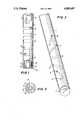
- FIG. 1is a side elevation of an optical fiber containing cells in accordance with the invention
- FIG. 2is a cross section of the optical fiber of FIG. 1;
- FIG. 3is a schematic perspective view of the optical fiber showing a helical disposition of the cells.
- FIGS. 1, 2 and 3 of the drawingcomprises an optical fiber 1 having a distal end with a reflective surface 2.
- the reflective surfaceis formed by a layer of reflective white particles of, for example, titanium dioxide or barium sulphate suspended in an epoxy resin. The curing of the resin forms a stable bond to the end of the fiber.
- the optical fiberis made from a suitable material for transmitting electromagnetic radiation; such as fused silica or an acrylic polymer, particularly polymethyl methacrylate.
- a suitable material for transmitting electromagnetic radiationsuch as fused silica or an acrylic polymer, particularly polymethyl methacrylate.
- the fiberwill have a diameter of 125 to 250 microns.
- a series of cells 3, 4, 5, 6, 7, 8is located in the fiber along a portion near to, but set back from, the distal end. These cells are formed by ablating holes in the fiber to form an array which substantially covers the cross-sectional area of the fiber as shown in plan in FIG. 2.
- a preferred arrangement to achieve the desired substantial coverageis a helical array as shown in perspective in FIG. 3.
- the desirability of an arrangement which provides substantial coverage over the cross-sectional area of the fiberis that such arrangement ensures that incident radiation transmitted from a source (not shown) to the distal end of the fiber and return reflected radiation pass through at least one indicator-containing cell and thereby provide an appropriate signal for determination of the analyte under investigation.
- the helical array illustrated in FIG. 3is not essential to provide the pattern illustrated in FIG. 2 since the directional sequence of the cells may be altered and still produce the same coverage. Furthermore, although in the illustrated embodiment the cells extend diametrically through the fiber, the desired coverage may be achieved with holes which do not extend through the full diameter of the fiber.
- each of the cells 3-8is of square cross-section. However, any convenient cross-section may be chosen.
- the configuration of said cross-sectionmay be determined by the shape of the mask through which the laser radiation is transmitted.
- the cellsare preferably formed by ablating the fiber with high energy radiation from a suitable laser, preferably an excimer laser.
- the cellswill usually be about 50 to 100 microns square respectively and the cells will be separated from each other by a distance of about 300 to 500 microns.
- FIG. 1the disposition of the cells with respect to each other and to the distal end of the fiber is illustrated in FIG. 1.
- the portion of the fiber containing the cellsis immersed in a solution of a suitable indicator.
- the assembly containing the solution and the fiberis then placed in a vacuum chamber wherein it is subjected to a vacuum so that the cells are evacuated.
- the solutionincludes ingredients capable of forming a gel or other suitable solid phase adapted to be cured or otherwise set so that the indicator is retained in the cells in a stable manner.
- a suitable indicator-containing compositionis illustrated hereinafter.
- the refractive index of the indicator-containing gelshould be matched to the refractive index of the optical fiber material.
- the senorWhen the indicator-containing gel or solid is retained in the cells the sensor is complete. In operating the sensor the portion of the optical fiber with the indicator-containing cells is immersed in a liquid medium containing the analyte under investigation.
- Source radiation of a suitable wavelengthis transmitted along the fiber toward the distal end 2.
- the incident radiationis represented by arrows 9 in FIG. 1.
- the incident radiationpasses through the indicator-containing cells, wherein some of its energy is absorbed, and reaches the reflective surface 2 as represented by arrows 10.
- the radiation reaching the reflective surfaceis reflected as represented by arrows 11 and the reflected signal passes again through the cells wherein energy is again absorbed and returns along the fiber, as represented by arrows 12, to a detector (not shown) where the signal is analyzed and the relative intensity gives a determination of the analyte.
- the difference in thickness of the arrows 9, 10, 11 and 12(not to scale) is intended to give a visual indication of the diminuation of intensity between the incident radiation and the return signal.
- the cellsare preferably formed by ablating the optical fiber with a high energy laser.
- Ablationis a term of art meaning to remove material from a solid, for example by cutting, melting or vaporization, and is used herein to mean the formation of holes without debris, for example by drilling or boring with laser radiation or other suitable drilling means.
- the ablationis preferably conducted by directing a beam of high energy electromagnetic radiation, preferably from an excimer laser, against a chosen point in the selected portion of the optical fiber for a time sufficient to form a hole or cell of the desired depth.
- a beam of high energy electromagnetic radiationpreferably from an excimer laser
- the time required to form the desired celldepends upon the nature and dimensions of the fiber and the energy of the laser radiation. For example, using laser radiation at a pulse rate of about 50 to 100. Hertz at an energy density of about 5 to 20 joules/sq. cm. the time to ablate holes through a 250 diameter polymeric optical fiber is about 5 to 10 seconds. In the preferred embodiment described herein the hole extends through the whole width of the fiber.
- the array of cells illustrated in FIGS. 1 to 3may be produced by at least two procedures.
- the first procedurecomprises ablating a first cell, for example the cell nearest the distal end of the fiber, moving the fiber longitudinally while turning it through an angle of 30° , ablating a second cell and repeating the moving, turning and ablating procedure until the desired number of cells, in this instance six, is formed.
- This procedurerequires a separate period of laser radiation for the formation of each hole or cell and means for synchronizing the moving, turning and ablating steps.
- the desired array of cellsis formed without moving the fiber, but by using a multiple-hole drilling rig whereby beams of radiation from a single laser are directed through a series of reflectors located around the portion of the fiber to be ablated.
- the location of each reflectordetermines the site of ablation for each cell in the desired array
- the reflectoris preferably a mirror or a prism.
- Exampleillustrates a preferred embodiment of the invention with reference to the materials used and the manner in which the invention is performed.
- An optical fiber having a diameter of 0.010 inches (250 microns) and made from polymethyl methacrylate with a fluorinated polymer claddingwas used to prepare a sensor according to the invention.
- each 100 microns squarewas ablated through the fiber using an excimer laser.
- Each cellpassed along a fiber diameter, and was rotated about 30° with respect to each adjacent cell.
- the longitudinal spacing between the cellswas about 300 to 500 microns.
- the resulting helical arrayensured that radiation transmitted through the fiber would have to traverse at least one cell.
- the distal end of the fiberwas cut square with a cutting blade and a reflective surface was bonded thereto.
- An optical connectorwas attached to the proximal end of the fiber (the fiber length being up to six feet).
- the solutioncontained 0.6 grams of a powdered mixture comprising 73% acrylamide, 14% N,N-methylene-bis acrylamide and 12% ammonium persulfate by weight, and 1.4 ml. of a 300 millimolar phosphate buffer adjusted to pH 7.80 and saturated with phenol red.
- the portion of the fiber with the six cellswas then immersed in the above indicator solution and subjected to a vacuum to remove air from the cells. Several drops of N,N,N',N'-tetramethylenediamine was added to the solution. Within a few minutes the liquid converted to a solid gel. The optical fiber was removed from the gel and placed in a pH 7.30 buffer. Inspection of the fiber revealed that the cells were now filled with gel and that, within the gel, a significant amount of phenol red was permanently immobilized.
- the fiber(now a pH sensor) was attached to a modified Cardiomet 4000® monitor (Biomedical Sensors Limited).
- the monitorprovided an appropriate light source (green and red light emitting diodes (LED)), detector (photodiode) and software to calibrate the sensor and then to use the sensor to measure the pH of unknown solutions.
- LEDgreen and red light emitting diodes
- detectorphotodiode
- the sensorwas accurately calibrated using three pH standards. (pH 1 , about 6.69; pH 2 about 7.29; pH 3 about 7.80 at room temperature). Calibration of the sensor was carried out according to the instructions provided with the monitor, i.e. in the known manner for the Cardiomet 4000® monitor.
- the resolution of the monitoris ⁇ 0.01 units.
- the response time of the sensor (0 to 90%)was about one minute.
Landscapes
- Physics & Mathematics (AREA)
- Chemical & Material Sciences (AREA)
- General Physics & Mathematics (AREA)
- Biochemistry (AREA)
- Engineering & Computer Science (AREA)
- Health & Medical Sciences (AREA)
- Life Sciences & Earth Sciences (AREA)
- Analytical Chemistry (AREA)
- Chemical Kinetics & Catalysis (AREA)
- General Health & Medical Sciences (AREA)
- Plasma & Fusion (AREA)
- Immunology (AREA)
- Pathology (AREA)
- Investigating Or Analysing Materials By The Use Of Chemical Reactions (AREA)
- Optical Measuring Cells (AREA)
- Investigating Or Analyzing Non-Biological Materials By The Use Of Chemical Means (AREA)
- Investigating Or Analysing Materials By Optical Means (AREA)
- Investigating, Analyzing Materials By Fluorescence Or Luminescence (AREA)
Abstract
Description
Claims (22)
Priority Applications (7)
| Application Number | Priority Date | Filing Date | Title |
|---|---|---|---|
| US07/279,384US4889407A (en) | 1988-12-02 | 1988-12-02 | Optical waveguide sensor and method of making same |
| DE68920842TDE68920842T2 (en) | 1988-12-02 | 1989-11-29 | Optical waveguide sensor. |
| ES89312382TES2066867T3 (en) | 1988-12-02 | 1989-11-29 | OPTICAL WAVE GUIDE SENSOR. |
| EP89312382AEP0372802B1 (en) | 1988-12-02 | 1989-11-29 | Optical waveguide sensor |
| CA002004250ACA2004250C (en) | 1988-12-02 | 1989-11-30 | Optical waveguide sensor |
| JP1313068AJPH06100547B2 (en) | 1988-12-02 | 1989-12-01 | Optical waveguide sensor and method for manufacturing the sensor |
| AU45800/89AAU610446B2 (en) | 1988-12-02 | 1989-12-01 | Optical waveguide sensor |
Applications Claiming Priority (1)
| Application Number | Priority Date | Filing Date | Title |
|---|---|---|---|
| US07/279,384US4889407A (en) | 1988-12-02 | 1988-12-02 | Optical waveguide sensor and method of making same |
Publications (1)
| Publication Number | Publication Date |
|---|---|
| US4889407Atrue US4889407A (en) | 1989-12-26 |
Family
ID=23068728
Family Applications (1)
| Application Number | Title | Priority Date | Filing Date |
|---|---|---|---|
| US07/279,384Expired - LifetimeUS4889407A (en) | 1988-12-02 | 1988-12-02 | Optical waveguide sensor and method of making same |
Country Status (7)
| Country | Link |
|---|---|
| US (1) | US4889407A (en) |
| EP (1) | EP0372802B1 (en) |
| JP (1) | JPH06100547B2 (en) |
| AU (1) | AU610446B2 (en) |
| CA (1) | CA2004250C (en) |
| DE (1) | DE68920842T2 (en) |
| ES (1) | ES2066867T3 (en) |
Cited By (55)
| Publication number | Priority date | Publication date | Assignee | Title |
|---|---|---|---|---|
| US5129025A (en)* | 1991-02-19 | 1992-07-07 | Texaco Inc. | Optical thermal sensing device in fired oil treaters |
| US5201755A (en)* | 1990-09-11 | 1993-04-13 | Datascope Investment Corp. | Method and apparatus for early detection of leakage and failure of a balloon membrane of a balloon catheter |
| WO1993006772A1 (en)* | 1991-10-09 | 1993-04-15 | Optex Biomedical, Inc. | Method and apparatus for measuring blood parameters |
| US5209231A (en)* | 1990-11-02 | 1993-05-11 | University Of Connecticut | Optical glucose sensor apparatus and method |
| US5257338A (en)* | 1992-05-22 | 1993-10-26 | Biomedical Sensors, Ltd. | Device for transmitting and returning light and apparatus and method of manufacture |
| WO1993025892A1 (en)* | 1992-06-10 | 1993-12-23 | Applied Research Systems Ars Holding N.V. | Sensor for optical assay |
| US5280130A (en)* | 1992-05-22 | 1994-01-18 | Biomedical Sensors, Ltd. | Assembly of a tube and a part and apparatus and method of manufacture |
| WO1994010553A1 (en)* | 1992-10-23 | 1994-05-11 | Optex Biomedical, Inc. | Fibre-optic probe for the measurement of fluid parameters |
| US5322986A (en)* | 1992-04-06 | 1994-06-21 | Eastman Kodak Company | Methods for preparing polymer stripe waveguides and polymer stripe waveguides prepared thereby |
| US5333609A (en)* | 1992-05-19 | 1994-08-02 | Minnesota Mining And Manufacturing Company | Catheter and probe-catheter assembly |
| US5335305A (en)* | 1991-12-19 | 1994-08-02 | Optex Biomedical, Inc. | Optical sensor for fluid parameters |
| US5342190A (en)* | 1992-07-22 | 1994-08-30 | Optex Biomedical, Inc. | Apparatus for emplacing viscous material in a cavity |
| US5347377A (en)* | 1992-06-17 | 1994-09-13 | Eastman Kodak Company | Planar waveguide liquid crystal variable retarder |
| US5353792A (en)* | 1992-09-25 | 1994-10-11 | Avl Medical Instruments Ag | Sensing device |
| US5357955A (en)* | 1992-05-22 | 1994-10-25 | Puritan-Bennett Corporation | Reinforced catheter probe |
| US5397411A (en)* | 1990-05-22 | 1995-03-14 | Optex Biomedical, Inc. | Method for making optical probe |
| US5560356A (en)* | 1994-02-23 | 1996-10-01 | Vitrophage, Inc. | Diagnostic system and method using an implanted reflective device |
| US5596988A (en)* | 1993-06-30 | 1997-01-28 | Biomedical Sensors, Ltd. | Multi-parameter sensor apparatus |
| WO1997012227A1 (en)* | 1995-09-28 | 1997-04-03 | Optical Sensors Incorporated | Optical carbon dioxide sensor, and associated methods of manufacture and use |
| US5622259A (en)* | 1995-06-07 | 1997-04-22 | Church; Jonathan M. | Reduction of discoloration in plastic materials |
| US5656241A (en)* | 1995-09-07 | 1997-08-12 | Optical Sensors Incorporated | Method for manufacturing fiber optic sensors |
| US5854863A (en)* | 1996-03-15 | 1998-12-29 | Erb; Judith | Surface treatment and light injection method and apparatus |
| WO1999064097A1 (en) | 1998-06-09 | 1999-12-16 | Diametrics Medical Limited | Double walled catheter and method of manufacture |
| US20030171711A1 (en)* | 2002-03-06 | 2003-09-11 | Rohr William L. | Closed-loop drug delivery system |
| US20030231818A1 (en)* | 2002-02-20 | 2003-12-18 | Institut National D'optique | Packaged optical sensors on the side of optical fibres |
| US6702972B1 (en) | 1998-06-09 | 2004-03-09 | Diametrics Medical Limited | Method of making a kink-resistant catheter |
| US20040243093A1 (en)* | 2001-01-10 | 2004-12-02 | Ron Berenson | System for growth, analysis, storage, validation and distribution of cells and tissues used for biomedical purposes |
| DE102004047498A1 (en)* | 2004-09-23 | 2006-04-20 | Siemens Ag | Optical fiber having a structured surface and method of making the same |
| US20060155177A1 (en)* | 1998-01-08 | 2006-07-13 | Curators Of The University Of Missouri | Method & apparatus for monitoring cerebral physiology |
| US20070047868A1 (en)* | 2005-08-25 | 2007-03-01 | Rene Beaulieu | Flow cytometry analysis across optical fiber |
| US20070104430A1 (en)* | 2005-10-21 | 2007-05-10 | Marc Levesque | Optical fiber devices using component insertion |
| US20080125759A1 (en)* | 2002-03-06 | 2008-05-29 | Codman & Shurtleff, Inc. | Convection-enhanced drug delivery device and method of use |
| US20080188725A1 (en)* | 2007-02-06 | 2008-08-07 | Markle David R | Optical systems and methods for ratiometric measurement of blood glucose concentration |
| WO2009106805A1 (en)* | 2008-02-26 | 2009-09-03 | Glysure Ltd | Fibre optic sensor |
| US7951583B2 (en) | 2006-03-10 | 2011-05-31 | Plc Diagnostics, Inc. | Optical scanning system |
| US8088097B2 (en) | 2007-11-21 | 2012-01-03 | Glumetrics, Inc. | Use of an equilibrium intravascular sensor to achieve tight glycemic control |
| US8288157B2 (en) | 2007-09-12 | 2012-10-16 | Plc Diagnostics, Inc. | Waveguide-based optical scanning systems |
| US8467843B2 (en) | 2009-11-04 | 2013-06-18 | Glumetrics, Inc. | Optical sensor configuration for ratiometric correction of blood glucose measurement |
| US8498682B2 (en) | 2007-02-06 | 2013-07-30 | Glumetrics, Inc. | Optical determination of pH and glucose |
| US8512245B2 (en) | 2008-04-17 | 2013-08-20 | Glumetrics, Inc. | Sensor for percutaneous intravascular deployment without an indwelling cannula |
| US8536542B2 (en) | 2006-08-25 | 2013-09-17 | Institut National D'optique | Flow cytometry analysis across optical fiber |
| US8607612B2 (en) | 2011-05-27 | 2013-12-17 | Lightship Medical Limited | Sensor calibration |
| US8675199B2 (en) | 2006-03-10 | 2014-03-18 | Plc Diagnostics, Inc. | Waveguide-based detection system with scanning light source |
| US8694069B1 (en)* | 2009-12-21 | 2014-04-08 | Kosense, LLC | Fiber-optic probe with embedded peripheral sensors for in-situ continuous monitoring |
| US8715589B2 (en) | 2009-09-30 | 2014-05-06 | Medtronic Minimed, Inc. | Sensors with thromboresistant coating |
| US8738107B2 (en) | 2007-05-10 | 2014-05-27 | Medtronic Minimed, Inc. | Equilibrium non-consuming fluorescence sensor for real time intravascular glucose measurement |
| US8747751B2 (en) | 2008-06-16 | 2014-06-10 | Plc Diagnostics, Inc. | System and method for nucleic acids sequencing by phased synthesis |
| US9017622B2 (en) | 2012-04-10 | 2015-04-28 | Lightship Medical Limited | Calibrator for a sensor |
| US9423397B2 (en) | 2006-03-10 | 2016-08-23 | Indx Lifecare, Inc. | Waveguide-based detection system with scanning light source |
| US9528939B2 (en) | 2006-03-10 | 2016-12-27 | Indx Lifecare, Inc. | Waveguide-based optical scanning systems |
| US9976192B2 (en) | 2006-03-10 | 2018-05-22 | Ldip, Llc | Waveguide-based detection system with scanning light source |
| US10018566B2 (en) | 2014-02-28 | 2018-07-10 | Ldip, Llc | Partially encapsulated waveguide based sensing chips, systems and methods of use |
| US11181479B2 (en) | 2015-02-27 | 2021-11-23 | Ldip, Llc | Waveguide-based detection system with scanning light source |
| US11255860B2 (en) | 2012-06-21 | 2022-02-22 | Baxter International Inc. | Glucose sensor |
| US20220313127A1 (en)* | 2016-07-29 | 2022-10-06 | Los Angeles Biomedical Research Institute At Harbor Ucla Medical Center | Integrated fiber optic sensor umbilical catheter |
Families Citing this family (6)
| Publication number | Priority date | Publication date | Assignee | Title |
|---|---|---|---|---|
| DE4128846C2 (en)* | 1991-08-30 | 1994-07-14 | Rainer Dr Klein | Integrated optical fabric sensor |
| GB2265709A (en)* | 1992-03-25 | 1993-10-06 | David Russell Blake | Reactive oxygen species measuring device |
| DE102008050109B4 (en)* | 2008-07-21 | 2010-06-17 | Ancosys Gmbh | Optical sensor |
| DE102011081326A1 (en) | 2011-08-22 | 2013-02-28 | Endress + Hauser Conducta Gesellschaft für Mess- und Regeltechnik mbH + Co. KG | Optical sensor for determining concentration of aqueous solution e.g. drinking water, has optical receiver which transmits electric signal to sensor elements for evaluating light characteristics |
| DE102019122096A1 (en)* | 2019-08-16 | 2021-02-18 | Endress+Hauser Conducta Gmbh+Co. Kg | Optochemical sensor and method |
| WO2024203845A1 (en)* | 2023-03-31 | 2024-10-03 | 古河電気工業株式会社 | Light diffusion device |
Citations (15)
| Publication number | Priority date | Publication date | Assignee | Title |
|---|---|---|---|---|
| US31879A (en)* | 1861-04-02 | Machine for finishing leatheb | ||
| JPS54155856A (en)* | 1978-05-29 | 1979-12-08 | Toshiba Corp | Optical fiber sensor |
| US4200110A (en)* | 1977-11-28 | 1980-04-29 | United States Of America | Fiber optic pH probe |
| US4344438A (en)* | 1978-08-02 | 1982-08-17 | The United States Of America As Represented By The Department Of Health, Education And Welfare | Optical sensor of plasma constituents |
| US4476870A (en)* | 1982-03-30 | 1984-10-16 | The United States Of America As Represented By The Department Of Health And Human Services | Fiber optic PO.sbsb.2 probe |
| USRE31879E (en) | 1975-02-28 | 1985-05-07 | Max-Planck-Gesellschaft Zur Forderung Der Wissenschaften E.V. | Method and arrangement for measuring the concentration of gases |
| US4560248A (en)* | 1981-08-14 | 1985-12-24 | Imperial Chemical Industries, Plc | Fibre optic sensor with bonded dye |
| US4600310A (en)* | 1981-03-30 | 1986-07-15 | Imperial Chemical Industries Plc | Optical fibre sensor |
| US4710623A (en)* | 1986-02-27 | 1987-12-01 | Eli Lilly And Company | Optical fiber catheter with fiber-contained reactive element |
| WO1988004415A1 (en)* | 1986-12-05 | 1988-06-16 | Conax Buffalo Corporation | Improved optical fiber temperature sensor |
| US4785814A (en)* | 1987-08-11 | 1988-11-22 | Cordis Corporation | Optical probe for measuring pH and oxygen in blood and employing a composite membrane |
| US4796633A (en)* | 1985-06-25 | 1989-01-10 | American Hospital Supply Corporation | Method and apparatus for in vitro calibration of oxygen saturation monitor |
| US4801187A (en)* | 1986-04-30 | 1989-01-31 | Baxter Travenol Laboratories, Inc. | Liquid light tube end cap assembly |
| US4803049A (en)* | 1984-12-12 | 1989-02-07 | The Regents Of The University Of California | pH-sensitive optrode |
| US4816130A (en)* | 1987-07-02 | 1989-03-28 | Becton, Dickinson And Company | Blood electrolyte sensors including crosslinked polyetherurethane membranes |
Family Cites Families (4)
| Publication number | Priority date | Publication date | Assignee | Title |
|---|---|---|---|---|
| EP0073558A3 (en)* | 1981-08-25 | 1984-09-26 | THE UNITED STATES OF AMERICA as represented by the Secretary United States Department of Commerce | Fiber optic ph probe for tissue measurements |
| EP0170375B1 (en)* | 1984-06-13 | 1990-05-16 | Unilever Plc | Devices for use in chemical test procedures |
| AU589619B2 (en)* | 1985-03-20 | 1989-10-19 | Monash University | Fibre optic chemical sensor |
| US4727730A (en)* | 1986-07-10 | 1988-03-01 | Medex, Inc. | Integrated optic system for monitoring blood pressure |
- 1988
- 1988-12-02USUS07/279,384patent/US4889407A/ennot_activeExpired - Lifetime
- 1989
- 1989-11-29DEDE68920842Tpatent/DE68920842T2/ennot_activeExpired - Fee Related
- 1989-11-29EPEP89312382Apatent/EP0372802B1/ennot_activeExpired - Lifetime
- 1989-11-29ESES89312382Tpatent/ES2066867T3/ennot_activeExpired - Lifetime
- 1989-11-30CACA002004250Apatent/CA2004250C/ennot_activeExpired - Fee Related
- 1989-12-01AUAU45800/89Apatent/AU610446B2/ennot_activeCeased
- 1989-12-01JPJP1313068Apatent/JPH06100547B2/ennot_activeExpired - Fee Related
Patent Citations (16)
| Publication number | Priority date | Publication date | Assignee | Title |
|---|---|---|---|---|
| US31879A (en)* | 1861-04-02 | Machine for finishing leatheb | ||
| USRE31879E (en) | 1975-02-28 | 1985-05-07 | Max-Planck-Gesellschaft Zur Forderung Der Wissenschaften E.V. | Method and arrangement for measuring the concentration of gases |
| US4200110A (en)* | 1977-11-28 | 1980-04-29 | United States Of America | Fiber optic pH probe |
| JPS54155856A (en)* | 1978-05-29 | 1979-12-08 | Toshiba Corp | Optical fiber sensor |
| US4344438A (en)* | 1978-08-02 | 1982-08-17 | The United States Of America As Represented By The Department Of Health, Education And Welfare | Optical sensor of plasma constituents |
| US4600310A (en)* | 1981-03-30 | 1986-07-15 | Imperial Chemical Industries Plc | Optical fibre sensor |
| US4560248A (en)* | 1981-08-14 | 1985-12-24 | Imperial Chemical Industries, Plc | Fibre optic sensor with bonded dye |
| US4476870A (en)* | 1982-03-30 | 1984-10-16 | The United States Of America As Represented By The Department Of Health And Human Services | Fiber optic PO.sbsb.2 probe |
| US4803049A (en)* | 1984-12-12 | 1989-02-07 | The Regents Of The University Of California | pH-sensitive optrode |
| US4796633A (en)* | 1985-06-25 | 1989-01-10 | American Hospital Supply Corporation | Method and apparatus for in vitro calibration of oxygen saturation monitor |
| US4710623A (en)* | 1986-02-27 | 1987-12-01 | Eli Lilly And Company | Optical fiber catheter with fiber-contained reactive element |
| US4801187A (en)* | 1986-04-30 | 1989-01-31 | Baxter Travenol Laboratories, Inc. | Liquid light tube end cap assembly |
| US4794619A (en)* | 1986-12-05 | 1988-12-27 | Conax Buffalo Corporation | Optical fiber temperature sensor |
| WO1988004415A1 (en)* | 1986-12-05 | 1988-06-16 | Conax Buffalo Corporation | Improved optical fiber temperature sensor |
| US4816130A (en)* | 1987-07-02 | 1989-03-28 | Becton, Dickinson And Company | Blood electrolyte sensors including crosslinked polyetherurethane membranes |
| US4785814A (en)* | 1987-08-11 | 1988-11-22 | Cordis Corporation | Optical probe for measuring pH and oxygen in blood and employing a composite membrane |
Cited By (81)
| Publication number | Priority date | Publication date | Assignee | Title |
|---|---|---|---|---|
| US5397411A (en)* | 1990-05-22 | 1995-03-14 | Optex Biomedical, Inc. | Method for making optical probe |
| US5201755A (en)* | 1990-09-11 | 1993-04-13 | Datascope Investment Corp. | Method and apparatus for early detection of leakage and failure of a balloon membrane of a balloon catheter |
| US5209231A (en)* | 1990-11-02 | 1993-05-11 | University Of Connecticut | Optical glucose sensor apparatus and method |
| US5129025A (en)* | 1991-02-19 | 1992-07-07 | Texaco Inc. | Optical thermal sensing device in fired oil treaters |
| WO1993006772A1 (en)* | 1991-10-09 | 1993-04-15 | Optex Biomedical, Inc. | Method and apparatus for measuring blood parameters |
| US5335305A (en)* | 1991-12-19 | 1994-08-02 | Optex Biomedical, Inc. | Optical sensor for fluid parameters |
| US5322986A (en)* | 1992-04-06 | 1994-06-21 | Eastman Kodak Company | Methods for preparing polymer stripe waveguides and polymer stripe waveguides prepared thereby |
| US5333609A (en)* | 1992-05-19 | 1994-08-02 | Minnesota Mining And Manufacturing Company | Catheter and probe-catheter assembly |
| EP0571113A1 (en) | 1992-05-22 | 1993-11-24 | Biomedical Sensors Ltd | Optical transmitter and reflector |
| US5280130A (en)* | 1992-05-22 | 1994-01-18 | Biomedical Sensors, Ltd. | Assembly of a tube and a part and apparatus and method of manufacture |
| US5357955A (en)* | 1992-05-22 | 1994-10-25 | Puritan-Bennett Corporation | Reinforced catheter probe |
| US5257338A (en)* | 1992-05-22 | 1993-10-26 | Biomedical Sensors, Ltd. | Device for transmitting and returning light and apparatus and method of manufacture |
| WO1993025892A1 (en)* | 1992-06-10 | 1993-12-23 | Applied Research Systems Ars Holding N.V. | Sensor for optical assay |
| US5994091A (en)* | 1992-06-10 | 1999-11-30 | Applied Research Systems Ars Holding N.V. | Optical sensor for enzyme and enzyme substrates |
| US5347377A (en)* | 1992-06-17 | 1994-09-13 | Eastman Kodak Company | Planar waveguide liquid crystal variable retarder |
| US5342190A (en)* | 1992-07-22 | 1994-08-30 | Optex Biomedical, Inc. | Apparatus for emplacing viscous material in a cavity |
| US5353792A (en)* | 1992-09-25 | 1994-10-11 | Avl Medical Instruments Ag | Sensing device |
| WO1994010553A1 (en)* | 1992-10-23 | 1994-05-11 | Optex Biomedical, Inc. | Fibre-optic probe for the measurement of fluid parameters |
| US5408999A (en)* | 1992-10-23 | 1995-04-25 | Optex Biomedical, Inc. | Fiber-optic probe for the measurement of fluid parameters |
| US5618587A (en)* | 1993-06-30 | 1997-04-08 | Biomedical Sensors, Ltd. | Vacuum rig apparatus |
| US5596988A (en)* | 1993-06-30 | 1997-01-28 | Biomedical Sensors, Ltd. | Multi-parameter sensor apparatus |
| US5560356A (en)* | 1994-02-23 | 1996-10-01 | Vitrophage, Inc. | Diagnostic system and method using an implanted reflective device |
| US5622259A (en)* | 1995-06-07 | 1997-04-22 | Church; Jonathan M. | Reduction of discoloration in plastic materials |
| US5656241A (en)* | 1995-09-07 | 1997-08-12 | Optical Sensors Incorporated | Method for manufacturing fiber optic sensors |
| US5900215A (en)* | 1995-09-07 | 1999-05-04 | Optical Sensors Incorporated | Fiber optic sensor |
| WO1997012227A1 (en)* | 1995-09-28 | 1997-04-03 | Optical Sensors Incorporated | Optical carbon dioxide sensor, and associated methods of manufacture and use |
| US5714121A (en)* | 1995-09-28 | 1998-02-03 | Optical Sensors Incorporated | Optical carbon dioxide sensor, and associated methods of manufacture |
| EP1245947A1 (en)* | 1995-09-28 | 2002-10-02 | Optical Sensors Incorporated | Carbon dioxide sensor |
| US5854863A (en)* | 1996-03-15 | 1998-12-29 | Erb; Judith | Surface treatment and light injection method and apparatus |
| US5952035A (en)* | 1996-03-15 | 1999-09-14 | Ia, Inc. | Surface treatment and light injection method and apparatus |
| US7317937B2 (en)* | 1998-01-08 | 2008-01-08 | Curators Of The University Of Missouri | Method and apparatus for monitoring cerebral physiology |
| US20060155177A1 (en)* | 1998-01-08 | 2006-07-13 | Curators Of The University Of Missouri | Method & apparatus for monitoring cerebral physiology |
| WO1999064097A1 (en) | 1998-06-09 | 1999-12-16 | Diametrics Medical Limited | Double walled catheter and method of manufacture |
| US6702972B1 (en) | 1998-06-09 | 2004-03-09 | Diametrics Medical Limited | Method of making a kink-resistant catheter |
| US20070255249A1 (en)* | 2001-01-10 | 2007-11-01 | Ron Berenson | System for growth, analysis, storage, validation and distribution of cells and tissues used for biomedical purposes |
| US20040243093A1 (en)* | 2001-01-10 | 2004-12-02 | Ron Berenson | System for growth, analysis, storage, validation and distribution of cells and tissues used for biomedical purposes |
| US7209605B2 (en)* | 2002-02-20 | 2007-04-24 | Institut National D'optique | Packaged optical sensors on the side of optical fibers |
| US20030231818A1 (en)* | 2002-02-20 | 2003-12-18 | Institut National D'optique | Packaged optical sensors on the side of optical fibres |
| US20030171711A1 (en)* | 2002-03-06 | 2003-09-11 | Rohr William L. | Closed-loop drug delivery system |
| US20080125759A1 (en)* | 2002-03-06 | 2008-05-29 | Codman & Shurtleff, Inc. | Convection-enhanced drug delivery device and method of use |
| US7108680B2 (en) | 2002-03-06 | 2006-09-19 | Codman & Shurtleff, Inc. | Closed-loop drug delivery system |
| DE102004047498A1 (en)* | 2004-09-23 | 2006-04-20 | Siemens Ag | Optical fiber having a structured surface and method of making the same |
| DE102004047498B4 (en)* | 2004-09-23 | 2010-12-30 | Siemens Ag | Optical fiber with a structured surface |
| US7835599B2 (en)* | 2005-08-25 | 2010-11-16 | Institut National D'optique | Flow cytometry analysis across optical fiber |
| US20070047868A1 (en)* | 2005-08-25 | 2007-03-01 | Rene Beaulieu | Flow cytometry analysis across optical fiber |
| US20070104430A1 (en)* | 2005-10-21 | 2007-05-10 | Marc Levesque | Optical fiber devices using component insertion |
| US7324724B2 (en)* | 2005-10-21 | 2008-01-29 | Institut National D'optique | Optical fiber devices using component insertion |
| US9423397B2 (en) | 2006-03-10 | 2016-08-23 | Indx Lifecare, Inc. | Waveguide-based detection system with scanning light source |
| US9528939B2 (en) | 2006-03-10 | 2016-12-27 | Indx Lifecare, Inc. | Waveguide-based optical scanning systems |
| US10590493B2 (en) | 2006-03-10 | 2020-03-17 | Ldip, Llc | Waveguide-based detection system with scanning light source |
| US7951583B2 (en) | 2006-03-10 | 2011-05-31 | Plc Diagnostics, Inc. | Optical scanning system |
| US10551318B2 (en) | 2006-03-10 | 2020-02-04 | Ldip, Llc | Waveguide-based optical scanning systems |
| US8187866B2 (en) | 2006-03-10 | 2012-05-29 | Plc Diagnostics, Inc. | Optical scanning system |
| US9976192B2 (en) | 2006-03-10 | 2018-05-22 | Ldip, Llc | Waveguide-based detection system with scanning light source |
| US8675199B2 (en) | 2006-03-10 | 2014-03-18 | Plc Diagnostics, Inc. | Waveguide-based detection system with scanning light source |
| US8536542B2 (en) | 2006-08-25 | 2013-09-17 | Institut National D'optique | Flow cytometry analysis across optical fiber |
| US9839378B2 (en) | 2007-02-06 | 2017-12-12 | Medtronic Minimed, Inc. | Optical systems and methods for ratiometric measurement of blood glucose concentration |
| US20080188725A1 (en)* | 2007-02-06 | 2008-08-07 | Markle David R | Optical systems and methods for ratiometric measurement of blood glucose concentration |
| US8498682B2 (en) | 2007-02-06 | 2013-07-30 | Glumetrics, Inc. | Optical determination of pH and glucose |
| US8983565B2 (en) | 2007-02-06 | 2015-03-17 | Medtronic Minimed, Inc. | Optical determination of pH and glucose |
| US8838195B2 (en) | 2007-02-06 | 2014-09-16 | Medtronic Minimed, Inc. | Optical systems and methods for ratiometric measurement of blood glucose concentration |
| US8738107B2 (en) | 2007-05-10 | 2014-05-27 | Medtronic Minimed, Inc. | Equilibrium non-consuming fluorescence sensor for real time intravascular glucose measurement |
| US8288157B2 (en) | 2007-09-12 | 2012-10-16 | Plc Diagnostics, Inc. | Waveguide-based optical scanning systems |
| US8979790B2 (en) | 2007-11-21 | 2015-03-17 | Medtronic Minimed, Inc. | Use of an equilibrium sensor to monitor glucose concentration |
| US8088097B2 (en) | 2007-11-21 | 2012-01-03 | Glumetrics, Inc. | Use of an equilibrium intravascular sensor to achieve tight glycemic control |
| US8535262B2 (en) | 2007-11-21 | 2013-09-17 | Glumetrics, Inc. | Use of an equilibrium intravascular sensor to achieve tight glycemic control |
| WO2009106805A1 (en)* | 2008-02-26 | 2009-09-03 | Glysure Ltd | Fibre optic sensor |
| US20110044576A1 (en)* | 2008-02-26 | 2011-02-24 | Barry Colin Crane | Fibre optic sensor |
| US8512245B2 (en) | 2008-04-17 | 2013-08-20 | Glumetrics, Inc. | Sensor for percutaneous intravascular deployment without an indwelling cannula |
| US8747751B2 (en) | 2008-06-16 | 2014-06-10 | Plc Diagnostics, Inc. | System and method for nucleic acids sequencing by phased synthesis |
| US8715589B2 (en) | 2009-09-30 | 2014-05-06 | Medtronic Minimed, Inc. | Sensors with thromboresistant coating |
| US8700115B2 (en) | 2009-11-04 | 2014-04-15 | Glumetrics, Inc. | Optical sensor configuration for ratiometric correction of glucose measurement |
| US8467843B2 (en) | 2009-11-04 | 2013-06-18 | Glumetrics, Inc. | Optical sensor configuration for ratiometric correction of blood glucose measurement |
| US8694069B1 (en)* | 2009-12-21 | 2014-04-08 | Kosense, LLC | Fiber-optic probe with embedded peripheral sensors for in-situ continuous monitoring |
| US8607612B2 (en) | 2011-05-27 | 2013-12-17 | Lightship Medical Limited | Sensor calibration |
| US9017622B2 (en) | 2012-04-10 | 2015-04-28 | Lightship Medical Limited | Calibrator for a sensor |
| US11255860B2 (en) | 2012-06-21 | 2022-02-22 | Baxter International Inc. | Glucose sensor |
| US10018566B2 (en) | 2014-02-28 | 2018-07-10 | Ldip, Llc | Partially encapsulated waveguide based sensing chips, systems and methods of use |
| US11181479B2 (en) | 2015-02-27 | 2021-11-23 | Ldip, Llc | Waveguide-based detection system with scanning light source |
| US20220313127A1 (en)* | 2016-07-29 | 2022-10-06 | Los Angeles Biomedical Research Institute At Harbor Ucla Medical Center | Integrated fiber optic sensor umbilical catheter |
| US12257049B2 (en)* | 2016-07-29 | 2025-03-25 | Los Angeles Biomedical Research Institute At Harbor Ucla Medical Center | Integrated fiber optic sensor umbilical catheter |
Also Published As
| Publication number | Publication date |
|---|---|
| AU610446B2 (en) | 1991-05-16 |
| CA2004250C (en) | 1994-03-08 |
| CA2004250A1 (en) | 1990-06-02 |
| EP0372802A2 (en) | 1990-06-13 |
| JPH02259453A (en) | 1990-10-22 |
| JPH06100547B2 (en) | 1994-12-12 |
| DE68920842T2 (en) | 1995-05-24 |
| EP0372802B1 (en) | 1995-01-25 |
| DE68920842D1 (en) | 1995-03-09 |
| EP0372802A3 (en) | 1991-06-12 |
| ES2066867T3 (en) | 1995-03-16 |
| AU4580089A (en) | 1990-07-12 |
Similar Documents
| Publication | Publication Date | Title |
|---|---|---|
| US4889407A (en) | Optical waveguide sensor and method of making same | |
| US5119463A (en) | Compound optical probe employing single optical waveguide | |
| US4622974A (en) | Apparatus and method for in-vivo measurements of chemical concentrations | |
| US5098659A (en) | Apparatus for continuously monitoring a plurality of chemical analytes through a single optical fiber and method of making | |
| US4727730A (en) | Integrated optic system for monitoring blood pressure | |
| DK170510B1 (en) | Sensor system and method for determining the pH of a liquid by means of the sensor system | |
| US5378432A (en) | Optical fiber pH microsensor and method of manufacture | |
| US5047627A (en) | Configuration fiber-optic blood gas sensor bundle and method of making | |
| US5093266A (en) | Sensor system | |
| US6103197A (en) | Method and apparatus for optically determining total hemoglobin concentration | |
| AU702224B2 (en) | Diagnostic test carrier with multi-layer test field and method in which it is used to determine an analyte | |
| US5330718A (en) | Sensor element and method for making the same | |
| EP0253492B1 (en) | Fibre-optic probe | |
| US4900381A (en) | Method for manufacturing a measuring probe | |
| US4771006A (en) | Optrode for sensing hydrocarbons | |
| US5271073A (en) | Optical fiber sensor and method of manufacture | |
| JP3305398B2 (en) | Optical fiber sensor | |
| JPS5917134A (en) | Measuring device for concentration of particle in liquid | |
| CA1326772C (en) | Sensor system | |
| Weigl et al. | Optical sensor instrumentation using absorption-and fluorescence-based capillary waveguide optrodes | |
| JPS59214768A (en) | Blood inspector |
Legal Events
| Date | Code | Title | Description |
|---|---|---|---|
| FEPP | Fee payment procedure | Free format text:PAYOR NUMBER ASSIGNED (ORIGINAL EVENT CODE: ASPN); ENTITY STATUS OF PATENT OWNER: LARGE ENTITY | |
| AS | Assignment | Owner name:BIOMEDICAL SENSORS LIMITED, ENGLAND Free format text:ASSIGNMENT OF ASSIGNORS INTEREST.;ASSIGNORS:MARKLE, DAVID R.;CRANE, BARRY C.;IRVINE, MICHAEL P.;REEL/FRAME:005039/0241 Effective date:19881215 | |
| STCF | Information on status: patent grant | Free format text:PATENTED CASE | |
| CC | Certificate of correction | ||
| FPAY | Fee payment | Year of fee payment:4 | |
| FPAY | Fee payment | Year of fee payment:8 | |
| AS | Assignment | Owner name:DIAMETRICS MEDICAL LIMITED, MINNESOTA Free format text:CHANGE OF NAME;ASSIGNOR:BIOMEDICAL SENSORS LIMITED;REEL/FRAME:008579/0790 Effective date:19970407 | |
| FPAY | Fee payment | Year of fee payment:12 | |
| AS | Assignment | Owner name:TGC RESEARCH LIMITED, UNITED KINGDOM Free format text:ASSIGNMENT OF ASSIGNORS INTEREST;ASSIGNOR:BIOMEDICAL SENSORS LIMITED (NOW KNOWN AS DIAMETRICS MEDICAL LIMITED - IN LIQUIDATION);REEL/FRAME:018015/0694 Effective date:20060721 Owner name:TGC RESEARCH LIMITED, UNITED KINGDOM Free format text:ASSIGNMENT OF ASSIGNORS INTEREST;ASSIGNOR:DIAMETRICS MEDICAL LIMITED - IN LIQUIDATION;REEL/FRAME:018015/0670 Effective date:20060721 Owner name:TGC RESEARCH LIMITED, UNITED KINGDOM Free format text:ASSIGNMENT OF ASSIGNORS INTEREST;ASSIGNOR:DIAMETRICS MEDICAL LIMITED - IN LIQUIDATION;REEL/FRAME:018015/0626 Effective date:20060721 Owner name:TGC RESEARCH LIMITED, UNITED KINGDOM Free format text:QUITCLAIM;ASSIGNOR:DIAMETRICS MEDICAL INC.;REEL/FRAME:018015/0666 Effective date:20060724 | |
| AS | Assignment | Owner name:MEDTRONIC MINIMED, INC., CALIFORNIA Free format text:ASSIGNMENT OF ASSIGNORS INTEREST;ASSIGNOR:GLUMETRICS, INC.;REEL/FRAME:033276/0465 Effective date:20140320 |