US4889271A - Feed roller - Google Patents
Feed rollerDownload PDFInfo
- Publication number
- US4889271A US4889271AUS07/123,467US12346787AUS4889271AUS 4889271 AUS4889271 AUS 4889271AUS 12346787 AUS12346787 AUS 12346787AUS 4889271 AUS4889271 AUS 4889271A
- Authority
- US
- United States
- Prior art keywords
- cover member
- roller body
- longitudinal axis
- projections
- contact portion
- Prior art date
- Legal status (The legal status is an assumption and is not a legal conclusion. Google has not performed a legal analysis and makes no representation as to the accuracy of the status listed.)
- Expired - Lifetime
Links
Images


Classifications
- B—PERFORMING OPERATIONS; TRANSPORTING
- B65—CONVEYING; PACKING; STORING; HANDLING THIN OR FILAMENTARY MATERIAL
- B65H—HANDLING THIN OR FILAMENTARY MATERIAL, e.g. SHEETS, WEBS, CABLES
- B65H27/00—Special constructions, e.g. surface features, of feed or guide rollers for webs
- G—PHYSICS
- G03—PHOTOGRAPHY; CINEMATOGRAPHY; ANALOGOUS TECHNIQUES USING WAVES OTHER THAN OPTICAL WAVES; ELECTROGRAPHY; HOLOGRAPHY
- G03D—APPARATUS FOR PROCESSING EXPOSED PHOTOGRAPHIC MATERIALS; ACCESSORIES THEREFOR
- G03D3/00—Liquid processing apparatus involving immersion; Washing apparatus involving immersion
- G03D3/08—Liquid processing apparatus involving immersion; Washing apparatus involving immersion having progressive mechanical movement of exposed material
- G03D3/13—Liquid processing apparatus involving immersion; Washing apparatus involving immersion having progressive mechanical movement of exposed material for long films or prints in the shape of strips, e.g. fed by roller assembly
- B—PERFORMING OPERATIONS; TRANSPORTING
- B65—CONVEYING; PACKING; STORING; HANDLING THIN OR FILAMENTARY MATERIAL
- B65H—HANDLING THIN OR FILAMENTARY MATERIAL, e.g. SHEETS, WEBS, CABLES
- B65H2404/00—Parts for transporting or guiding the handled material
- B65H2404/10—Rollers
- B65H2404/11—Details of cross-section or profile
- B65H2404/111—Details of cross-section or profile shape
- B65H2404/1115—Details of cross-section or profile shape toothed roller
- B—PERFORMING OPERATIONS; TRANSPORTING
- B65—CONVEYING; PACKING; STORING; HANDLING THIN OR FILAMENTARY MATERIAL
- B65H—HANDLING THIN OR FILAMENTARY MATERIAL, e.g. SHEETS, WEBS, CABLES
- B65H2404/00—Parts for transporting or guiding the handled material
- B65H2404/10—Rollers
- B65H2404/13—Details of longitudinal profile
- B65H2404/131—Details of longitudinal profile shape
- B65H2404/1311—Undulations, wavy shape
- B—PERFORMING OPERATIONS; TRANSPORTING
- B65—CONVEYING; PACKING; STORING; HANDLING THIN OR FILAMENTARY MATERIAL
- B65H—HANDLING THIN OR FILAMENTARY MATERIAL, e.g. SHEETS, WEBS, CABLES
- B65H2404/00—Parts for transporting or guiding the handled material
- B65H2404/10—Rollers
- B65H2404/13—Details of longitudinal profile
- B65H2404/134—Axle
- B—PERFORMING OPERATIONS; TRANSPORTING
- B65—CONVEYING; PACKING; STORING; HANDLING THIN OR FILAMENTARY MATERIAL
- B65H—HANDLING THIN OR FILAMENTARY MATERIAL, e.g. SHEETS, WEBS, CABLES
- B65H2404/00—Parts for transporting or guiding the handled material
- B65H2404/10—Rollers
- B65H2404/18—Rollers composed of several layers
- B65H2404/181—Rollers composed of several layers with cavities or projections at least at one layer
- B—PERFORMING OPERATIONS; TRANSPORTING
- B65—CONVEYING; PACKING; STORING; HANDLING THIN OR FILAMENTARY MATERIAL
- B65H—HANDLING THIN OR FILAMENTARY MATERIAL, e.g. SHEETS, WEBS, CABLES
- B65H2404/00—Parts for transporting or guiding the handled material
- B65H2404/50—Surface of the elements in contact with the forwarded or guided material
- B65H2404/52—Surface of the elements in contact with the forwarded or guided material other geometrical properties
- B65H2404/521—Reliefs
Definitions
- the present inventionrelates to a feed roller suitable for use in feeding a sheet-like object in a clamped manner.
- feeder arrangements of the type employing rollersare utilized in various fields which necessitate the feeding of sheet-like objects.
- a feeder arrangementis incorporated in automatic development machines as a means of causing a long photographic film to pass through a series of processing baths.
- the gap between the rollersis preferably made as narrow as possible in order to allow the film to be nipped therebetween.
- the gap between the rollersis preferably made wide so as to reduce the level of clamping reaction force applied to these surfaces. Accordingly, in order to suitably maintain the clamping force applied to the film, it has been necessary to adjust the sizes of the respective gaps between opposing rollers.
- a feed roller for feeding an object in a clamped mannercomprising a hard roller body; a cylindrical resilient cover member fitted onto the hard roller body; an internal contact portion formed on an inner surface of the cover member, the internal contact portion being kept in contact with the outer periphery of the hard roller body when the cover member is fitted onto the hard roller body; an external contact portion formed on an outer surface of the cover member so as to project outwardly in the radial direction of the cover member; and a space portion which defines a space between the inner surface of the external contact portion and the outer periphery of the hard roller body.
- an improved feed rollerhaving external contact portions formed to abut against a sheet-like object.
- the improved feed rollerincludes a plurality of spaces that are defined along the periphery of its body by space portions of a cover member fitted onto the body so as to impart a suitable degree of resiliency to the cover member. Accordingly, the sheet-like object is positively fed by the resultant small clamping reaction force arising from the cover member, thereby preventing the object from being damaged.
- the inventive feed rollercan easily be assembled since only internal contact portions of the cover member are brought into intimate contact with the periphery of the body.
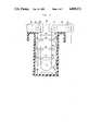
- FIG. 1is a diagrammatic longitudinal section of an automatic development machine which incorporates a plurality of feed rollers constituting a first preferred embodiment of the present invention
- FIG. 2is an enlarged diagrammatic longitudinal section of a development bath provided in the automatic development machine shown in FIG. 1;
- FIG. 3is a diagrammatic explosion showing in perspective a development rack including feed rollers of the invention.
- FIG. 4is an enlarged perspective view of the first preferred embodiment of the feed roller in accordance with the present invention.
- FIG. 5is a fragmentary cross section of the body and cover member which constitute in combination the first embodiment
- FIG. 6is an enlarged perspective view of a second preferred embodiment of the feed roller in accordance with the present invention.
- FIG. 7is a fragmentary cross section of the second embodiment of the feed roller
- FIG. 8is an enlarged perspective view of a third preferred embodiment of the feed roller in accordance with the present invention.
- FIG. 9is a fragmentary cross section of the third embodiment of the feed roller.
- FIG. 10is a cross section taken along line X--X of FIG. 9.
- FIG. 1is a diagrammatic longitudinal section of an automatic development machine which incorporates a plurality of feed rollers each constituting a first preferred embodiment of the present invention.
- An automatic development machine indicated generally at 10includes an upstream section serving as an exposure section 12 (the left-hand portion in FIG. 1) and a downstream section serving as a development section 14 (the right-hand portion in FIG. 1).
- a roll of photographic paper 18is accommodated in a magazine 16 of the exposure section 12.
- a predetermined length of the photographic paper 18is supplied sequentially from the outer circumference of the roll toward the optical axis of optical means 20.
- the thus-supplied portion of the photographic paper 18is then exposed to an image or images on a negative film 22 by the optical means 20.
- the exposed portion of the photographic paper 18is fed to the development section 14 via a buffer-loop forming section 24 which is designed to absorb a difference between the feed speeds of the photographic paper 18 in the exposure section 12 and the development section 14.
- the development section 14includes a development bath 26, a bleaching bath 28, a fixation bath 30, a washing bath 32, and a stabilization bath 34, and each of these processing baths is charged with a predetermined processing liquid.
- the exposed portion of the photographic paper 18is developed as it passes through these processing baths.
- each of the processing bathsincludes means for agitating and circulating the processing liquid therein.
- the thus-developed portion of the photographic paper 18is dried in a drying chamber 36 and is then discharged therefrom.
- a development rack indicated generally at 40is accommodated in each of the processing baths.
- the photographic paper 18is guided over rollers supported by the development rack 40 in each of the processing liquids filled in the above-described processing baths.
- the development rack 40includes a pair of rack side plates 42 and 44 which are firmly connected parallel to each other by a plurality of shafts 46.
- a support roller 48is supported for rotation about its longitudinal axis by portions near the lower ends of the rack side plates 42 and 44, and the photographic paper 18 is partially wound around the support roller 48 and is looped back upward thereby in the vicinity of the bottom of each of the processing baths.
- Pairs of a feed roller 50 of the present invention and a conventional type feed roller 52are rotatably supported by the rack side plates 42 and 44 so as to guide the photographic paper 18 in each of the processing baths.
- FIG. 3illustrates one pair of the feed rollers 50 and 52.
- the feed rollers 50are arranged in a face-to-face relationship with one surface of the photographic paper 18 as it is being moved through the processing baths, that is, with the outer surface of the portion of the photographic paper 18 which is looped back by the support rollers 48.
- the feed rollers 50are each constituted by a body 54 and a cover member 56.
- the body made of a hard materialhas a cylindrical form, and has a central shaft 58 which extends along the longitudinal axis of the body.
- the feed roller 50is supported at the opposite ends of the shaft 58 for rotation about its longitudinal axis between the rack side plates 42 and 44.
- the cover member 56is fitted onto the periphery of the body 54.
- the cover member 56 having a bellows-like formis blow-molded with a thermoplastic elastomer. As shown in FIG. 5, the inner diameter of each internal contact portion 60 is equal to or slightly smaller than the outer diameter of the body 54. External contact portions 62 project outwardly of the cover member 56 extending continuously from each of the internal contact portions 60 to form a series of annular ridges.
- the feed rollers 50 and 52are disposed parallel to each other in such a manner that the external contact portions 62 abut against or are spaced slightly apart from the periphery of the feed roller 52.
- the cover member 56can be resiliently deformed along its longitudinal axis and in its radial direction. Accordingly, the cover member 56 can be readily fitted onto the body 54.
- the cover member 56has space portions 64 which define a plurality of spaces between the periphery of the body 54 and the inner surface of the cover member 56. Therefore, when fitted onto the body 54, the cover member 56 can be provided with a suitable degree of resiliency. Accordingly, while the photographic paper 18 is being guided and fed through the nips between the cover members 56 on the feed rollers 50 and the associated feed rollers 52, the emulsion bearing surface of the photographic paper 18 is clamped by a suitable level of reaction force arising from the cover members 56.
- a support roller 68is supported for rotation about its axis by a bracket 70 on the top of the development bath 26 so that the photographic paper 18 supplied from the exposure section 12 may be partially wound around the support roller 68 and be then looped downward into the development bath 26.
- support rollers 72 and 74are supported for rotation about its axis by a bracket 76 so as to feed the photographic paper 18 from the development bath 26 to the bleaching bath 28.
- the support rollers 48 and the feed rollers 50, 52are rotated about their respective axes by a drive force of a motor (not shown) to feed the photographic paper 18 from the exposure section 12 to the development section 14 including the respective baths.
- the portion of the photographic paper 18 that is exposed to an image by the optical means 20is fed to the development section 14 with the emulsion bearing surface being faced down.
- the photographic paper 18is partially wound around the support roller 68 and is looped downward thereby.
- the photographic paper 18is sequentially passed through the nips between the feed rollers 50 and 52.
- the emulsion bearing surface of the photographic paper 18corresponds to the feed rollers 50 and therefore the external contact portions 62 on the cover members 56 come into contact with the emulsion bearing surface.
- a plurality of spacesare defined along the periphery of each of the bodies 54 by the space portions 64 of the cover member 56 fitted onto the body 54, thereby imparting a suitable degree of resiliency to the cover members 56. Accordingly, the cover members 56 are caused to abut against the emulsion bearing surface of the photographic paper 18 by the resultant small clamping reaction force, thereby preventing the emulsion bearing surface from being damaged.
- FIGS. 6 and 7illustrate the second embodiment of the present invention.
- a feed roller indicated generally at 78includes the body 54, and a cover member 80 is fitted onto the body 54.
- the cover member 80which is produced by extruding a thermoplastic elastomer, has a plurality of projecting external contact portions 80 which extend along the longitudinal axis of the cover member 80 and which are formed in equally spaced apart relationship around the circumference thereof.
- the inner diameter around which the internal contact portions 84 are locatedis equal to or slightly smaller than the outer diameter of the body 54.
- the cover member 80has space portions 86 which define a plurality of spaces between the periphery of the body 54 and the inner surface of the cover member 84. Therefore, when fitted onto the body 54, the cover member 84 can be provided with a suitable degree of resiliency.
- the cover member 80according to the second embodiment has a simple form and can be readily produced by extrusion.
- the material of the cover member 80is not limited solely to an extruded thermoplastic elastomer and, for example, an injection-molded thermoplastic elastomer or a press-molded synthetic rubber material may be employed.
- FIGS. 8, 9 and 10illustrate a third preferred embodiment of the present invention.
- a feed roller indicated generally at 88includes a body 90 and a cover member 92.
- the body 90has a substantially cylindrical form, and a central shaft 94 is fixed to radial stays 96 extending along the longitudinal axis of the body 90.
- a plurality of axially extending recesses 90are formed in the periphery of the body 90.
- the cover member 92is formed of a thermoplastic elastomer, and a plurality of projections 100 project inwardly from the inner circumference of the cover member 92.
- the projections 100are formed in lines corresponding to the axially extending recesses 98 formed in the body 90, and each line of the spherical projections 100 is adapted to engage with the corresponding recess 98. Accordingly, after the cover member 92 has been fitted onto the body 90, the cover member 92 is prevented from shifting circumferentially about the body 90.
- a plurality of projections 102 serving as external contact portionsare formed on the periphery of the cover member 92.
- the projections 102each have a hollow form with a space portion 104 so that a suitable degree of resiliency is generated in the projections 102. Accordingly, while the photographic paper 18 is being guided and fed through the nips between the cover members 92 on the feed rollers 88 and the associated feed rollers 52, the emulsion bearing surface of the photographic paper 18 is clamped by a suitable level of reaction force arising from the cover members 92, thereby preventing the emulsion bearing surface from being damaged.
- each line of the projections 100 on the cover member 92is adapted to engage with the corresponding recess 98. Accordingly, after the cover member 92 has been fitted onto the body 90, the cover member 92 is prevented from shifting circumferentially about the body 90 to ensure that the cover member 92 is further positively fitted onto the body 54.
- the feed rollers of the present inventionare applied to the automatic development machine 10 by way of example.
- this usageis illustrative and not restrictive.
- the present inventionis applicable to sheet feed or discharge rollers in a copying machine.
- the material of the cover memberis not limited to a thermoplastic elastomer.
- a resilient materialsuch as a synthetic rubber or a synthetic resin may be employed.
Landscapes
- Physics & Mathematics (AREA)
- General Physics & Mathematics (AREA)
- Delivering By Means Of Belts And Rollers (AREA)
- Rolls And Other Rotary Bodies (AREA)
- Photographic Processing Devices Using Wet Methods (AREA)
- Registering, Tensioning, Guiding Webs, And Rollers Therefor (AREA)
Abstract
Description
Claims (11)
Applications Claiming Priority (2)
| Application Number | Priority Date | Filing Date | Title |
|---|---|---|---|
| JP1986185888UJPS6390652U (en) | 1986-12-02 | 1986-12-02 | |
| JP61-185888 | 1986-12-02 |
Publications (1)
| Publication Number | Publication Date |
|---|---|
| US4889271Atrue US4889271A (en) | 1989-12-26 |
Family
ID=16178635
Family Applications (1)
| Application Number | Title | Priority Date | Filing Date |
|---|---|---|---|
| US07/123,467Expired - LifetimeUS4889271A (en) | 1986-12-02 | 1987-11-20 | Feed roller |
Country Status (2)
| Country | Link |
|---|---|
| US (1) | US4889271A (en) |
| JP (1) | JPS6390652U (en) |
Cited By (13)
| Publication number | Priority date | Publication date | Assignee | Title |
|---|---|---|---|---|
| EP0558875A1 (en)* | 1992-03-06 | 1993-09-08 | Multitec Ag | Device for developing one side of a web or sheetlike light-sensitive material |
| US5417360A (en)* | 1993-09-28 | 1995-05-23 | Moore Business Forms, Inc. | Feeding of offset, collated forms |
| US5645361A (en)* | 1993-08-31 | 1997-07-08 | Shinko Electric Co., Ltd. | Thermal-transfer-type color printer having a feed roller with micro projections |
| US6557742B1 (en)* | 2001-04-18 | 2003-05-06 | Lincoln Global, Inc. | Drive roller for wire feeding mechanism |
| WO2003086922A1 (en)* | 2002-04-08 | 2003-10-23 | 3M Innovative Properties Company | Sheet feed apparatus, sheet separating member, sheet feed assembly and sheet separating assembly |
| US20040026844A1 (en)* | 2002-06-02 | 2004-02-12 | Naoyuki Toriumi | Elastic member and paper feeding roller using same |
| US20040259707A1 (en)* | 1999-06-30 | 2004-12-23 | Karin Lochte | Tampon having apertured film cover thermobonded to fibrous absorbent structure |
| US20050016976A1 (en)* | 2003-07-22 | 2005-01-27 | Lincoln Global, Inc., A Delware Corporation | Wire gripper for a drive unit of a wire feeder |
| US20060241556A1 (en)* | 1999-06-30 | 2006-10-26 | Karin Lochte | Tampon having apertured film cover thermobonded to fibrous absorbent structure |
| US20080064581A1 (en)* | 2004-07-21 | 2008-03-13 | Karin Lochte | Tampon Having Apertured Film Cover Thermobonded to Fibrous Absorbent Structure |
| US20100038350A1 (en)* | 2008-08-18 | 2010-02-18 | Lincoln Global, Inc. | Wire feeder with curved force generating element(s) for better positioning of an adjusting mechanism |
| WO2017189737A1 (en)* | 2016-04-26 | 2017-11-02 | Sun Automation, Inc. | Feed/pull roll system with detachable elastomeric feed-covers, and process for cover replacement |
| US9845216B2 (en) | 2009-09-24 | 2017-12-19 | 3M Innovative Properties Company | Web conveyance method and apparatus using same |
Families Citing this family (1)
| Publication number | Priority date | Publication date | Assignee | Title |
|---|---|---|---|---|
| JP6989714B2 (en)* | 2019-01-17 | 2022-01-05 | 富士通フロンテック株式会社 | Paper leaf handling equipment and transport members |
Citations (8)
| Publication number | Priority date | Publication date | Assignee | Title |
|---|---|---|---|---|
| GB776400A (en)* | 1954-04-29 | 1957-06-05 | Vereingte Glanzstoff Fabriken | Improvements relating to thread-guiding rollers |
| US3170576A (en)* | 1962-08-24 | 1965-02-23 | Pennsalt Chemicals Corp | Rotary seal |
| US3187409A (en)* | 1963-05-07 | 1965-06-08 | Ames American Co | Method of securing resilient material covers to a roll |
| US3235940A (en)* | 1964-01-10 | 1966-02-22 | Eastman Kodak Co | Paper sheet-feed roller |
| US3493161A (en)* | 1967-04-17 | 1970-02-03 | Eastman Kodak Co | Web support roller surface |
| SU515146A1 (en)* | 1973-06-26 | 1976-05-25 | Каунасский Политехнический Институт | Tape roller |
| JPS5598050A (en)* | 1979-01-16 | 1980-07-25 | Rengo Co Ltd | Roll in transfer process of corrugated cardboard sheet |
| US4544253A (en)* | 1983-02-22 | 1985-10-01 | Kuemmerl Hermann | Conveying system for passing photographic layer-bearing carriers of strip or sheet form through the photo chemical baths of a developing apparatus |
- 1986
- 1986-12-02JPJP1986185888Upatent/JPS6390652U/jaactivePending
- 1987
- 1987-11-20USUS07/123,467patent/US4889271A/ennot_activeExpired - Lifetime
Patent Citations (8)
| Publication number | Priority date | Publication date | Assignee | Title |
|---|---|---|---|---|
| GB776400A (en)* | 1954-04-29 | 1957-06-05 | Vereingte Glanzstoff Fabriken | Improvements relating to thread-guiding rollers |
| US3170576A (en)* | 1962-08-24 | 1965-02-23 | Pennsalt Chemicals Corp | Rotary seal |
| US3187409A (en)* | 1963-05-07 | 1965-06-08 | Ames American Co | Method of securing resilient material covers to a roll |
| US3235940A (en)* | 1964-01-10 | 1966-02-22 | Eastman Kodak Co | Paper sheet-feed roller |
| US3493161A (en)* | 1967-04-17 | 1970-02-03 | Eastman Kodak Co | Web support roller surface |
| SU515146A1 (en)* | 1973-06-26 | 1976-05-25 | Каунасский Политехнический Институт | Tape roller |
| JPS5598050A (en)* | 1979-01-16 | 1980-07-25 | Rengo Co Ltd | Roll in transfer process of corrugated cardboard sheet |
| US4544253A (en)* | 1983-02-22 | 1985-10-01 | Kuemmerl Hermann | Conveying system for passing photographic layer-bearing carriers of strip or sheet form through the photo chemical baths of a developing apparatus |
Non-Patent Citations (2)
| Title |
|---|
| "A Soft Touch Surface Designed for Scratch-Free Motion-Picture Film Processing", C. J. Crane, W. L. Stogkdale & L. R. Witherow, Eastman Kodak Co., J. SMPTE 79/No. 8/712-715 (1970). |
| A Soft Touch Surface Designed for Scratch Free Motion Picture Film Processing , C. J. Crane, W. L. Stogkdale & L. R. Witherow, Eastman Kodak Co., J. SMPTE 79/No. 8/712 715 (1970).* |
Cited By (25)
| Publication number | Priority date | Publication date | Assignee | Title |
|---|---|---|---|---|
| EP0558875A1 (en)* | 1992-03-06 | 1993-09-08 | Multitec Ag | Device for developing one side of a web or sheetlike light-sensitive material |
| US5645361A (en)* | 1993-08-31 | 1997-07-08 | Shinko Electric Co., Ltd. | Thermal-transfer-type color printer having a feed roller with micro projections |
| US5417360A (en)* | 1993-09-28 | 1995-05-23 | Moore Business Forms, Inc. | Feeding of offset, collated forms |
| US5553763A (en)* | 1993-09-28 | 1996-09-10 | Moore Business Forms, Inc. | Feeding of offset, collated forms |
| US20040259707A1 (en)* | 1999-06-30 | 2004-12-23 | Karin Lochte | Tampon having apertured film cover thermobonded to fibrous absorbent structure |
| US7857800B2 (en) | 1999-06-30 | 2010-12-28 | Johnson & Johnson Gmbh | Tampon having apertured film cover thermobonded to fibrous absorbent structure |
| US20060241556A1 (en)* | 1999-06-30 | 2006-10-26 | Karin Lochte | Tampon having apertured film cover thermobonded to fibrous absorbent structure |
| US6557742B1 (en)* | 2001-04-18 | 2003-05-06 | Lincoln Global, Inc. | Drive roller for wire feeding mechanism |
| US20030222394A1 (en)* | 2002-04-08 | 2003-12-04 | Koichi Sano | Sheet feed apparatus, sheet separating member, sheet feed assembly and sheet separating assembly |
| WO2003086922A1 (en)* | 2002-04-08 | 2003-10-23 | 3M Innovative Properties Company | Sheet feed apparatus, sheet separating member, sheet feed assembly and sheet separating assembly |
| EP1762517A1 (en)* | 2002-04-08 | 2007-03-14 | 3M Innovative Properties Company | Sheet feed apparatus, sheet separating member, sheet feed assembly and sheet separating assembly |
| US20040026844A1 (en)* | 2002-06-02 | 2004-02-12 | Naoyuki Toriumi | Elastic member and paper feeding roller using same |
| US7687742B2 (en) | 2003-07-22 | 2010-03-30 | Lincoln Global, Inc. | Wire gripper for a drive unit of a wire feeder |
| US20060138114A1 (en)* | 2003-07-22 | 2006-06-29 | Lincoln Global, Inc. | Wire gripper for a drive unit of a wire feeder |
| US20070108172A1 (en)* | 2003-07-22 | 2007-05-17 | Lincoln Global, Inc. | Wire gripper for a drive unit of a wire feeder |
| US20050016976A1 (en)* | 2003-07-22 | 2005-01-27 | Lincoln Global, Inc., A Delware Corporation | Wire gripper for a drive unit of a wire feeder |
| US7692117B2 (en) | 2003-07-22 | 2010-04-06 | Lincoln Global, Inc. | Wire gripper for a drive unit of a wire feeder |
| US7026574B2 (en) | 2003-07-22 | 2006-04-11 | Lincoln Global, Inc. | Wire gripper for a drive unit of a wire feeder |
| US20080064581A1 (en)* | 2004-07-21 | 2008-03-13 | Karin Lochte | Tampon Having Apertured Film Cover Thermobonded to Fibrous Absorbent Structure |
| US20100038350A1 (en)* | 2008-08-18 | 2010-02-18 | Lincoln Global, Inc. | Wire feeder with curved force generating element(s) for better positioning of an adjusting mechanism |
| US8878097B2 (en) | 2008-08-18 | 2014-11-04 | Lincoln Global, Inc. | Wire feeder with curved force generating element(s) for better positioning of an adjusting mechanism |
| US9845216B2 (en) | 2009-09-24 | 2017-12-19 | 3M Innovative Properties Company | Web conveyance method and apparatus using same |
| US10486932B2 (en) | 2009-09-24 | 2019-11-26 | 3M Innovative Properties Company | Web conveyance apparatus |
| WO2017189737A1 (en)* | 2016-04-26 | 2017-11-02 | Sun Automation, Inc. | Feed/pull roll system with detachable elastomeric feed-covers, and process for cover replacement |
| CN109689540A (en)* | 2016-04-26 | 2019-04-26 | 太阳自动化股份有限公司 | Feed/pull roll system with removable elastomeric feed cover and method for replacing the cover |
Also Published As
| Publication number | Publication date |
|---|---|
| JPS6390652U (en) | 1988-06-13 |
Similar Documents
| Publication | Publication Date | Title |
|---|---|---|
| US4889271A (en) | Feed roller | |
| EP0511424B1 (en) | Sheetlike article conveying roller assembly | |
| US5130754A (en) | Conveying rotatable member and conveying apparatus | |
| DE69003269T2 (en) | Fixing device. | |
| US4933726A (en) | Copy paper discharge rollers for copying machine | |
| JPH08127456A (en) | Curl removing device for reducing crosswise curl of sheet | |
| US4525057A (en) | Guide path for transfer of sheets to a fixing apparatus of a copying machine | |
| US4172975A (en) | Drying and fixing device | |
| US20200285187A1 (en) | Drive force transmission mechanism and image forming apparatus | |
| US5745816A (en) | Roller for use in a photographic sheet material processing apparatus | |
| US3369765A (en) | Web transport system | |
| US4922278A (en) | Developing apparatus | |
| US4302002A (en) | Sheet transportation belt apparatus | |
| US5479232A (en) | Photographic processing station with cleaning rollers | |
| KR960038478A (en) | Photographic photosensitive material transfer device | |
| US5523817A (en) | Photosensitive material processing apparatus | |
| US20240002157A1 (en) | Belt unit and image forming apparatus | |
| JP7641819B2 (en) | Belt unit, transfer device, and image forming apparatus | |
| US6993276B2 (en) | Belt apparatus and image forming apparatus having the same | |
| US9298153B2 (en) | Decurling device and image forming apparatus | |
| JP2861347B2 (en) | Endless belt conveyor | |
| US5884115A (en) | Photosensitive material processing apparatus | |
| JP3112218B2 (en) | Photosensitive material processing equipment | |
| JP3641879B2 (en) | Rack for photosensitive material conveyance | |
| KR100297768B1 (en) | Developing device of wet electrophotographic type printer |
Legal Events
| Date | Code | Title | Description |
|---|---|---|---|
| AS | Assignment | Owner name:FUJI PHOTO FILM CO., LTD.,, JAPAN Free format text:ASSIGNMENT OF ASSIGNORS INTEREST.;ASSIGNOR:KUROKAWA, TOSHIO;REEL/FRAME:005201/0155 Effective date:19871110 | |
| STCF | Information on status: patent grant | Free format text:PATENTED CASE | |
| FEPP | Fee payment procedure | Free format text:PAYOR NUMBER ASSIGNED (ORIGINAL EVENT CODE: ASPN); ENTITY STATUS OF PATENT OWNER: LARGE ENTITY | |
| FPAY | Fee payment | Year of fee payment:4 | |
| FPAY | Fee payment | Year of fee payment:8 | |
| FEPP | Fee payment procedure | Free format text:PAYER NUMBER DE-ASSIGNED (ORIGINAL EVENT CODE: RMPN); ENTITY STATUS OF PATENT OWNER: LARGE ENTITY Free format text:PAYOR NUMBER ASSIGNED (ORIGINAL EVENT CODE: ASPN); ENTITY STATUS OF PATENT OWNER: LARGE ENTITY | |
| FPAY | Fee payment | Year of fee payment:12 | |
| AS | Assignment | Owner name:FUJIFILM CORPORATION, JAPAN Free format text:ASSIGNMENT OF ASSIGNORS INTEREST;ASSIGNOR:FUJIFILM HOLDINGS CORPORATION (FORMERLY FUJI PHOTO FILM CO., LTD.);REEL/FRAME:020817/0190 Effective date:20080225 Owner name:FUJIFILM CORPORATION,JAPAN Free format text:ASSIGNMENT OF ASSIGNORS INTEREST;ASSIGNOR:FUJIFILM HOLDINGS CORPORATION (FORMERLY FUJI PHOTO FILM CO., LTD.);REEL/FRAME:020817/0190 Effective date:20080225 |