US4889199A - Downhole valve for use when drilling an oil or gas well - Google Patents
Downhole valve for use when drilling an oil or gas wellDownload PDFInfo
- Publication number
- US4889199A US4889199AUS07/054,713US5471387AUS4889199AUS 4889199 AUS4889199 AUS 4889199AUS 5471387 AUS5471387 AUS 5471387AUS 4889199 AUS4889199 AUS 4889199A
- Authority
- US
- United States
- Prior art keywords
- casing
- sleeve
- packer
- fluid
- outlet
- Prior art date
- Legal status (The legal status is an assumption and is not a legal conclusion. Google has not performed a legal analysis and makes no representation as to the accuracy of the status listed.)
- Expired - Fee Related
Links
- 238000005553drillingMethods0.000titleclaimsabstractdescription31
- 239000012530fluidSubstances0.000claimsabstractdescription44
- 230000015572biosynthetic processEffects0.000claimsdescription15
- 238000007599dischargingMethods0.000claimsdescription12
- 230000000903blocking effectEffects0.000claims2
- 239000000463materialSubstances0.000abstractdescription9
- 239000004033plasticSubstances0.000abstractdescription3
- 229920003023plasticPolymers0.000abstractdescription3
- 238000005086pumpingMethods0.000description6
- 239000002184metalSubstances0.000description4
- 230000000717retained effectEffects0.000description4
- 230000002265preventionEffects0.000description3
- 239000003381stabilizerSubstances0.000description3
- 238000004891communicationMethods0.000description2
- 230000002706hydrostatic effectEffects0.000description2
- 229910000831SteelInorganic materials0.000description1
- 230000000740bleeding effectEffects0.000description1
- 230000000694effectsEffects0.000description1
- 238000000034methodMethods0.000description1
- 229920002635polyurethanePolymers0.000description1
- 239000004814polyurethaneSubstances0.000description1
- 230000000630rising effectEffects0.000description1
- 125000006850spacer groupChemical group0.000description1
- 239000010959steelSubstances0.000description1
- XLYOFNOQVPJJNP-UHFFFAOYSA-NwaterSubstancesOXLYOFNOQVPJJNP-UHFFFAOYSA-N0.000description1
Images


Classifications
- E—FIXED CONSTRUCTIONS
- E21—EARTH OR ROCK DRILLING; MINING
- E21B—EARTH OR ROCK DRILLING; OBTAINING OIL, GAS, WATER, SOLUBLE OR MELTABLE MATERIALS OR A SLURRY OF MINERALS FROM WELLS
- E21B21/00—Methods or apparatus for flushing boreholes, e.g. by use of exhaust air from motor
- E21B21/003—Means for stopping loss of drilling fluid
- E—FIXED CONSTRUCTIONS
- E21—EARTH OR ROCK DRILLING; MINING
- E21B—EARTH OR ROCK DRILLING; OBTAINING OIL, GAS, WATER, SOLUBLE OR MELTABLE MATERIALS OR A SLURRY OF MINERALS FROM WELLS
- E21B21/00—Methods or apparatus for flushing boreholes, e.g. by use of exhaust air from motor
- E21B21/10—Valve arrangements in drilling-fluid circulation systems
- E21B21/103—Down-hole by-pass valve arrangements, i.e. between the inside of the drill string and the annulus
- E—FIXED CONSTRUCTIONS
- E21—EARTH OR ROCK DRILLING; MINING
- E21B—EARTH OR ROCK DRILLING; OBTAINING OIL, GAS, WATER, SOLUBLE OR MELTABLE MATERIALS OR A SLURRY OF MINERALS FROM WELLS
- E21B31/00—Fishing for or freeing objects in boreholes or wells
- E21B31/03—Freeing by flushing
- E—FIXED CONSTRUCTIONS
- E21—EARTH OR ROCK DRILLING; MINING
- E21B—EARTH OR ROCK DRILLING; OBTAINING OIL, GAS, WATER, SOLUBLE OR MELTABLE MATERIALS OR A SLURRY OF MINERALS FROM WELLS
- E21B31/00—Fishing for or freeing objects in boreholes or wells
- E21B31/035—Fishing for or freeing objects in boreholes or wells controlling differential pipe sticking
- E—FIXED CONSTRUCTIONS
- E21—EARTH OR ROCK DRILLING; MINING
- E21B—EARTH OR ROCK DRILLING; OBTAINING OIL, GAS, WATER, SOLUBLE OR MELTABLE MATERIALS OR A SLURRY OF MINERALS FROM WELLS
- E21B33/00—Sealing or packing boreholes or wells
- E21B33/10—Sealing or packing boreholes or wells in the borehole
- E21B33/12—Packers; Plugs
- E21B33/127—Packers; Plugs with inflatable sleeve
- E—FIXED CONSTRUCTIONS
- E21—EARTH OR ROCK DRILLING; MINING
- E21B—EARTH OR ROCK DRILLING; OBTAINING OIL, GAS, WATER, SOLUBLE OR MELTABLE MATERIALS OR A SLURRY OF MINERALS FROM WELLS
- E21B34/00—Valve arrangements for boreholes or wells
- E21B34/06—Valve arrangements for boreholes or wells in wells
- E21B34/14—Valve arrangements for boreholes or wells in wells operated by movement of tools, e.g. sleeve valves operated by pistons or wire line tools
- E21B34/142—Valve arrangements for boreholes or wells in wells operated by movement of tools, e.g. sleeve valves operated by pistons or wire line tools unsupported or free-falling elements, e.g. balls, plugs, darts or pistons
Definitions
- This inventionrelates to a device for use in downhole drilling, and in particular to a downhole device for use when drilling an oil or gas well.
- the present inventionrelates to a downhole drilling device for a hollow drill string; first outlet means in said casing means for discharging fluid from said casing means; sleeve means slidably mounted in said casing means; spring means in said casing means biasing said sleeve means to a closed position in which said sleeve means closes said first outlet means; second outlet means in said sleeve means for discharging fluid from said sleeve means when said first and second outlet means are aligned; and retainer means in said sleeve means for releasably retaining a ball, whereby when a ball is placed in said sleeve means to prevent the normal flow of drilling fluid through said sleeve means, said sleeve means is caused to move relative to said casing means into an open position in which said first and second outlet means are aligned to discharge fluid from above the ball through said casing means.
- FIGS. 1 to 4are partly sectioned side views of the downhole drilling device in accordance with the present invention.
- FIG. 5is a partly sectioned side view of a ball catcher device for use with the drilling device of FIGS. 1 to 4;
- FIG. 6is a schematic, longitudinal sectional view of a second embodiment of the device of the present invention.
- FIGS. 7a, 7b, 7c, and 8a, 8b, and 8care longitudinal sectional views of the device of FIG. 6 on a larger scale.
- FIGS. 9 and 10are partly sectioned side views of a third embodiment of the device of the present invention.
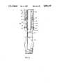
- one embodiment of the downhole device of the present inventionis a bypass sub defined by a tubular casing 1 with an internally threaded top end 2, and an externally threaded bottom end 3 for mounting the casing 1 in a drill string.
- An outlet opening 5is provided on one side of the casing 1 for discharging fluid from the interior of the casing.
- the opening 5is normally closed by a sleeve 6, which is slidably mounted in the casing 1.
- 0-rings 7 above and below the opening 5provide fluid seals between the casing 1 and the sleeve 6.
- the sleeve 6is retained in the casing 1 by a retainer ring 9 mounted in the casing beneath the threaded top end 2 thereof.
- Downward movement of the sleeve 6 in the casingis limited by a shoulder 10 on the sleeve 6 and a ledge 12 on the interior of the casing 1.
- Vertical movement of an annular floating piston 13is facilitated by movement of the sleeve 6.
- a chamber containing a spring 16, i.e. the chamber defined by the bottom, outer wall of the sleeve 6, the interior of the casing 1, the shoulder 10 and an annular ledge 17contains hydraulic fluid.
- Rotation of the sleeve 6 in the casing 1is prevented by a guide pin 14 extending radially inwardly through the casing 1 into a longitudinally extending slot (not shown) in the outer surface of the sleeve 6.
- the sleeve 6is biased to the closed position over the opening 5 by the helical spring 16, which extends between the shoulder 10 and the annular ledge 17 above the guide pin 14.
- An outlet opening 18is provided in one or more sides of the sleeve 6. The outlet opening 18 is vertically aligned with the opening 5 in the casing 1.
- a lost circulation conditioni.e. when drilling fluid is being lost to the formation, and it is desired to inject lost circulation material into the formation
- the drill stringis broken at the surface, and a large plastic ball 20 is placed therein.
- the ball 20descends to the casing 1 (i.e. to the bypass sub).
- the ball 20can be pumped through a portion of the drill string above the casing 1 in order to speed up feeding of the ball.
- pumpingshould be stopped at least two barrels before the ball 20 reaches the casing 1 (FIG. 2). Subsequently, the ball engages an inwardly inclined shoulder 21 on the interior of the sleeve 6.
- the pump pressure in the drill stringcauses the ball 20 to push the sleeve 6 downwardly against the force of the spring 16 until the shoulder 10 engages the ledge 12. In this position, the openings 5 and 18 are aligned, so that lost circulation material such as woodchips can be discharged into the formation.
- the stringis again broken at the surface, and a smaller metal ball 23 (FIG. 3) is dropped into the string. Pumping is then continued to cause the metal ball 23 to bear against the opening 18.
- Continued pumping of drilling mud into the casing 1forces the balls 20 and 23 downwardly through the sleeve 6 into a ball catcher device generally indicated at 25. This procedure can be repeated as often as necessary. It is necessary to ensure that all of the loose circulation material is discharged from the casing 1 in order to prevent plugging of the bit jets (not shown).
- the ball catcher device 25is defined by a tubular casing 26, with an internally threaded top end 27 and an externally threaded bottom end 29 for mounting the casing in a drill string.
- a ball retainer sleeve 30is mounted on a shoulder 31 in the casing 26.
- the sleeve 30is defined by annular top and bottom ends 33 and 34, respectively and thin strips or ribs 36 extending vertically between such ends 33 and 34.
- An annular stop 37is provided on the interior of the sleeve 30 near the bottom end thereof.
- the balls 20 and 23 discharged from the casing 1enter the casing 26 and are retained by the sleeve 30 while permitting the flow of drilling fluid through the passage 38 surrounding the sleeve 30, and through the spaces between the ribs 36.
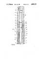
- a second embodiment of the inventionincludes the same basic elements of the first embodiment, namely a bypass sub generally indicated at 40, and an inflatable packer generally indicated at 41.
- the bypass sub 40is defined by a casing 43 for slidably housing a sleeve 44.
- the sleeve 44is retained in the casing 43 by a retainer ring 46 and a top sub defined by a casing 47.
- the casing 47has an internally threaded top end 48 and an externally threaded bottom end 49 for mounting the casing 47 in a drill string and in the casing 43.
- the sleeve 44is slidably mounted in the casing 43 for normally closing outlets 50 and 51 (one of each shown).
- the outlets 50define the top ends of passages 53 extending downwardly through the casing 43, and the outlets 51 are located in radially extending ports 54 (one shown) in the casing 43.
- 0-rings 56provide seals between the casing 43 and the sleeve 44 above and below the openings 50 and 51.
- the ports 54extend through the casing 43 to circulating jets or orifices 57 in a circulation cap defined by a sleeve 58 mounted on the casing 43.
- the upper limit of travel of the sleeve 44 in the casing 43is determined by the retainer ring 46.
- the lower limit of travel of the sleeve 44is determined by a ledge 59 in the casing 43, and a shoulder 60 on the sleeve 44.
- Outlet openings 62are provided in the sleeve 44. Such outlets are normally above and vertically aligned with the outlets 50 and 51 in the casing 43.
- the sleeve 44is normally retained in the upper closed position by a helical spring 64 extending between the shoulder 60 and a second ledge 65 in the casing 43.
- a stabilizer defined by a sleeve 67 and a plurality of longitudinally extending fins 68is slidably mounted on the casing 43.
- the stabilizeris formed of polyurethane or steel, and does not rotate with the casing 43.
- Annular friction pads 70are provided between the casing 43 and the sleeve 67.
- Teeth 72are provided on the bottom end of the casing 43 for engaging the top end of a cylindrical wash over clutch 73.
- a spacer ring 74is provided between the stabilizer and the clutch 73.
- the casing 43extends downwardly into the cylindrical top cap 75 of the packer 41. Seals 76 are provided between the cap 75 and the casing 43.
- the casing 43is internally threaded near the bottom end thereof for retaining the externally threaded top end 77 of a cylindrical mandrel 78, which extends through the packer to the internally threaded top end 79 of an elongated, tubular flex joint 80.
- the packer 41is slidably mounted on the bottom end of the casing 43 and the mandrel 78 by means of a retainer nut 82 and a thrust bearing 83. Seals 85 are provided between the nut 82 on the bottom end of the casing 43 and the interior of the top cap 75.
- a seal 86is provided at the base of the top cap 75.
- the passages 53 in the casing 43extend downwardly and then radially inwardly into fluid communication with the top ends of longitudinally extending passages 88 in the top end of the mandrel 78.
- the bottom ends of the passages 88are closed by a flexible, annular check valve 89.
- Passages 90extend radially outwardly from the passages 88 through the mandrel 78 and the casing 43 into fluid communication with a cylindrical chamber 91 between the casing 43 and the top cap 75 of the packer 41.
- the body of the packer 41is defined by a flexible, inflatable cylinder 93 which is connected to the bottom end of the top cap 75.
- the rigid bottom end 95 of the packer bodyis internally threaded for connecting the bottom nd of the packer to an externally threaded bottom cap 96.
- Seals 97are provided between the bottom cap 96 and the mandrel 78.
- Longitudinally extending recesses or flutes 99are provided in the mandrel communicating with an annular passage 101 between the bottom end of the mandrel 78 and the bottom end 95 of the packer 41. Should an over inflation situation occur, fluid will be discharged from the packer 41 via the flutes 99, the passage 101 in the bottom end of the packer, and passages 102 in the mandrel 78.
- the passages 102include inclined, radially extending top ends 104, and radially extending bottom ends aligned with radially extending passages 105 in the top end of the flex joint 80.
- the outer ends of the passages 105are normally closed by a flexible check valve 107. Seals 108 are provided between the bottom end of the mandrel 78 and the flex joint 80 above and below the passages 105.
- the packer 41seats on the flex joint 80 (FIG. 7c ).
- the drill stringis broken at the surface, a ball 110 is dropped into the string, and the connection is retorqued. If desired, the ball 110 can be pumped a portion of the distance to the device.
- additional drilling fluid pumped into the stringforces the sleeve 44 downwardly so that the openings 62 are aligned with the openings 50 and 51.
- the drilling fluidthen passes through the passages 53, 88 and 90 into the chamber 91 to push the packer 41 upwardly on the mandrel 78 to the upper position. In such position, the discharge passages 102 no longer communicate with the bottom of the packer 41. With the packer 41 in its uppermost position, the drilling fluid passes through the one-way check valve 89 into the space between the mandrel 78 and the packer body 93 to inflate the latter against the walls of the well.
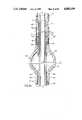
- FIGS. 9 and 10Since the third embodiment of the invention (FIGS. 9 and 10) is similar to the device of FIGS. 1 to 4, wherever possible the same reference numerals have been used to identify the same or similar elements.
- the basic difference between the third and first embodiments of the inventionis that the opening 18 and the shoulder 21 are omitted from the sleeve 21.
- the thickness of the top portion of the sleeve 6is constant from the internally bevelled top end 110 thereof to the shoulder 10.
- the 0-rings 7are mounted in and carried by the sleeve 6.
- the 0-rings 7are normally located above and below the opening 5 in the casing 1.
- the operation of the third embodiment of the inventionis the same as that of the first embodiment, except that the large plastic ball 20 seats on the top end 110 of the sleeve 6.
- Pump pressurecauses the ball 20 to push the sleeve 6 downwardly against the force of the spring 16 until the shoulder 10 engages the ledge 12.
- the top end 110 of the sleeve 6is below the opening 5, so that lost circulation material can be discharged into the formation.
- the stringis again broken at the surface, and a smaller metal ball 23 (FIG. 10) is dropped into the string. Pumping is then continued to cause the metal ball 23 to bear against the opening 5.
- Continued pumping of drilling mud into the casing 1forces the balls 20 and 23 downwardly through the sleeve 6 into the ball catcher device 25.
- Blowout preventionDuring conventional blowout prevention, when the hydrostatic pressure in the drill string is too low, the entire drill string must be filled as quickly as possible with heavy mud to hold gas in the formation. If heavy mud filling is not accomplished sufficiently quickly, gas starts to move up the hole to the surface. As the gas rises it expands. Conventional blowout tools are used to seal the hole at the surface where the gas pressure is highest and the danger the greatest. Surface tools give a variety of results, are sometimes ineffective and often leave a well sealed and useless.
- the packer 41When using the device of the present invention, as soon as a so-called "kick" occurs, presaging a blowout, the packer 41 is inflated in the manner described above.
- the prevention or control of blowouts in a holeis better than ground level action, since the gas at the downhole location has less opportunity to expand than when rising to the surface.
- By bleeding off the gas and adjusting the hydrostatic pressure in the string to counteract downhole gas pressuredrilling can be continued in relative safety.
- water or a lighter (less dense) fluidis used to remove the heavy mud from the drill string via ports 54, and the pressure is increased to drive the ball 110 through the sleeve 44 to the ball catcher device.
- the pressure below the packer 41will equalize with the reduced pressure in the drill string to create a U-tube effect which should free the pipe.
- the lighter fluidcan be reverse circulated out of the string.
- Preventing lost circulation--Normally, it is not possible to control the flow of annular fluid in the event of lost circulation.
- the annulus below the packercan be sealed, and circulation restricted to the area above the packer.
- suitable lost circulation materialOnce suitable lost circulation material has been prepared by the operator, the material can be pumped downwardly to shortly above the ball 110. The pressure is increased to force the ball 110 through the device, and to circulate the lost circulation material into the weak formation beneath the packer 41. The material is permitted to set or, if necessary, forced into the formation under pressure.
Landscapes
- Engineering & Computer Science (AREA)
- Life Sciences & Earth Sciences (AREA)
- Geology (AREA)
- Mining & Mineral Resources (AREA)
- Physics & Mathematics (AREA)
- Environmental & Geological Engineering (AREA)
- Fluid Mechanics (AREA)
- General Life Sciences & Earth Sciences (AREA)
- Geochemistry & Mineralogy (AREA)
- Mechanical Engineering (AREA)
- Marine Sciences & Fisheries (AREA)
- Earth Drilling (AREA)
- Consolidation Of Soil By Introduction Of Solidifying Substances Into Soil (AREA)
Abstract
Description
This invention relates to a device for use in downhole drilling, and in particular to a downhole device for use when drilling an oil or gas well.
During the drilling of oil or gas wells, problems often arise because of differences in the pressures in the geological formation being drilled and at the surface, or between the pressure of the drilling mud and the formation pressure. Three major problems of this type include blowouts, differential sticking and mud circulation loss. Any of these problems can be extremely dangerous, and often require expensive solutions.
Accordingly, the present invention relates to a downhole drilling device for a hollow drill string; first outlet means in said casing means for discharging fluid from said casing means; sleeve means slidably mounted in said casing means; spring means in said casing means biasing said sleeve means to a closed position in which said sleeve means closes said first outlet means; second outlet means in said sleeve means for discharging fluid from said sleeve means when said first and second outlet means are aligned; and retainer means in said sleeve means for releasably retaining a ball, whereby when a ball is placed in said sleeve means to prevent the normal flow of drilling fluid through said sleeve means, said sleeve means is caused to move relative to said casing means into an open position in which said first and second outlet means are aligned to discharge fluid from above the ball through said casing means.
The invention will be described in greater detail with reference to the accompanying drawings, which illustrate preferred emobdiments of the invention, and wherein:
FIGS. 1 to 4 are partly sectioned side views of the downhole drilling device in accordance with the present invention;
FIG. 5 is a partly sectioned side view of a ball catcher device for use with the drilling device of FIGS. 1 to 4;
FIG. 6 is a schematic, longitudinal sectional view of a second embodiment of the device of the present invention;
FIGS. 7a, 7b, 7c, and 8a, 8b, and 8c are longitudinal sectional views of the device of FIG. 6 on a larger scale; and
FIGS. 9 and 10 are partly sectioned side views of a third embodiment of the device of the present invention.
With reference to FIGS. 1 to 4, one embodiment of the downhole device of the present invention is a bypass sub defined by a tubular casing 1 with an internally threadedtop end 2, and an externally threadedbottom end 3 for mounting the casing 1 in a drill string. An outlet opening 5 is provided on one side of the casing 1 for discharging fluid from the interior of the casing. The opening 5 is normally closed by asleeve 6, which is slidably mounted in the casing 1. 0-rings 7 above and below the opening 5 provide fluid seals between the casing 1 and thesleeve 6. Thesleeve 6 is retained in the casing 1 by aretainer ring 9 mounted in the casing beneath the threadedtop end 2 thereof. Downward movement of thesleeve 6 in the casing is limited by ashoulder 10 on thesleeve 6 and aledge 12 on the interior of the casing 1. Vertical movement of an annular floatingpiston 13 is facilitated by movement of thesleeve 6. A chamber containing aspring 16, i.e. the chamber defined by the bottom, outer wall of thesleeve 6, the interior of the casing 1, theshoulder 10 and anannular ledge 17 contains hydraulic fluid. Rotation of thesleeve 6 in the casing 1 is prevented by aguide pin 14 extending radially inwardly through the casing 1 into a longitudinally extending slot (not shown) in the outer surface of thesleeve 6. Thesleeve 6 is biased to the closed position over theopening 5 by thehelical spring 16, which extends between theshoulder 10 and theannular ledge 17 above theguide pin 14. An outlet opening 18 is provided in one or more sides of thesleeve 6. The outlet opening 18 is vertically aligned with the opening 5 in the casing 1.
During a lost circulation condition, i.e. when drilling fluid is being lost to the formation, and it is desired to inject lost circulation material into the formation, the drill string is broken at the surface, and a largeplastic ball 20 is placed therein. Theball 20 descends to the casing 1 (i.e. to the bypass sub). Theball 20 can be pumped through a portion of the drill string above the casing 1 in order to speed up feeding of the ball. However, pumping should be stopped at least two barrels before theball 20 reaches the casing 1 (FIG. 2). Subsequently, the ball engages an inwardlyinclined shoulder 21 on the interior of thesleeve 6. The pump pressure in the drill string causes theball 20 to push thesleeve 6 downwardly against the force of thespring 16 until theshoulder 10 engages the ledge 12. In this position, theopenings metal ball 23 to bear against the opening 18. Continued pumping of drilling mud into the casing 1 forces theballs sleeve 6 into a ball catcher device generally indicated at 25. This procedure can be repeated as often as necessary. It is necessary to ensure that all of the loose circulation material is discharged from the casing 1 in order to prevent plugging of the bit jets (not shown).
Referring to FIG. 5, theball catcher device 25 is defined by atubular casing 26, with an internally threadedtop end 27 and an externally threadedbottom end 29 for mounting the casing in a drill string. Aball retainer sleeve 30 is mounted on ashoulder 31 in thecasing 26. Thesleeve 30 is defined by annular top andbottom ends ribs 36 extending vertically betweensuch ends sleeve 30 near the bottom end thereof.
Thus, theballs casing 26 and are retained by thesleeve 30 while permitting the flow of drilling fluid through thepassage 38 surrounding thesleeve 30, and through the spaces between theribs 36.
With reference to FIGS. 6 to 8, a second embodiment of the invention includes the same basic elements of the first embodiment, namely a bypass sub generally indicated at 40, and an inflatable packer generally indicated at 41. Thebypass sub 40 is defined by acasing 43 for slidably housing asleeve 44. Thesleeve 44 is retained in thecasing 43 by aretainer ring 46 and a top sub defined by acasing 47. Thecasing 47 has an internally threadedtop end 48 and an externally threadedbottom end 49 for mounting thecasing 47 in a drill string and in thecasing 43.
Like thesleeve 6, thesleeve 44 is slidably mounted in thecasing 43 for normally closingoutlets 50 and 51 (one of each shown). Theoutlets 50 define the top ends ofpassages 53 extending downwardly through thecasing 43, and theoutlets 51 are located in radially extending ports 54 (one shown) in thecasing 43. 0-rings 56 provide seals between thecasing 43 and thesleeve 44 above and below theopenings
Theports 54 extend through thecasing 43 to circulating jets ororifices 57 in a circulation cap defined by asleeve 58 mounted on thecasing 43.
The upper limit of travel of thesleeve 44 in thecasing 43 is determined by theretainer ring 46. The lower limit of travel of thesleeve 44 is determined by aledge 59 in thecasing 43, and ashoulder 60 on thesleeve 44.Outlet openings 62 are provided in thesleeve 44. Such outlets are normally above and vertically aligned with theoutlets casing 43. Thesleeve 44 is normally retained in the upper closed position by ahelical spring 64 extending between theshoulder 60 and asecond ledge 65 in thecasing 43. A stabilizer defined by asleeve 67 and a plurality of longitudinally extendingfins 68 is slidably mounted on thecasing 43. The stabilizer is formed of polyurethane or steel, and does not rotate with thecasing 43.Annular friction pads 70 are provided between thecasing 43 and thesleeve 67. Teeth 72 (one shown) are provided on the bottom end of thecasing 43 for engaging the top end of a cylindrical wash overclutch 73. Aspacer ring 74 is provided between the stabilizer and theclutch 73.
Thecasing 43 extends downwardly into the cylindricaltop cap 75 of thepacker 41.Seals 76 are provided between thecap 75 and thecasing 43. Thecasing 43 is internally threaded near the bottom end thereof for retaining the externally threadedtop end 77 of acylindrical mandrel 78, which extends through the packer to the internally threadedtop end 79 of an elongated, tubular flex joint 80. Thepacker 41 is slidably mounted on the bottom end of thecasing 43 and themandrel 78 by means of aretainer nut 82 and athrust bearing 83.Seals 85 are provided between thenut 82 on the bottom end of thecasing 43 and the interior of thetop cap 75. Aseal 86 is provided at the base of thetop cap 75. Thepassages 53 in thecasing 43 extend downwardly and then radially inwardly into fluid communication with the top ends of longitudinally extendingpassages 88 in the top end of themandrel 78. The bottom ends of thepassages 88 are closed by a flexible,annular check valve 89.Passages 90 extend radially outwardly from thepassages 88 through themandrel 78 and thecasing 43 into fluid communication with acylindrical chamber 91 between thecasing 43 and thetop cap 75 of thepacker 41.
The body of thepacker 41 is defined by a flexible,inflatable cylinder 93 which is connected to the bottom end of thetop cap 75. The rigidbottom end 95 of the packer body is internally threaded for connecting the bottom nd of the packer to an externally threadedbottom cap 96.Seals 97 are provided between thebottom cap 96 and themandrel 78. Longitudinally extending recesses orflutes 99 are provided in the mandrel communicating with an annular passage 101 between the bottom end of themandrel 78 and thebottom end 95 of thepacker 41. Should an over inflation situation occur, fluid will be discharged from thepacker 41 via theflutes 99, the passage 101 in the bottom end of the packer, andpassages 102 in themandrel 78. Thepassages 102 include inclined, radially extending top ends 104, and radially extending bottom ends aligned with radially extendingpassages 105 in the top end of the flex joint 80. The outer ends of thepassages 105 are normally closed by aflexible check valve 107.Seals 108 are provided between the bottom end of themandrel 78 and the flex joint 80 above and below thepassages 105.
During normal operation of the drill string, thepacker 41 seats on the flex joint 80 (FIG. 7c ). When it is desired to inflate thepacker 41, the drill string is broken at the surface, aball 110 is dropped into the string, and the connection is retorqued. If desired, theball 110 can be pumped a portion of the distance to the device. When theball 110 seats in the top end of the sleeve 44 (FIG. 8a), additional drilling fluid pumped into the string forces thesleeve 44 downwardly so that theopenings 62 are aligned with theopenings passages chamber 91 to push thepacker 41 upwardly on themandrel 78 to the upper position. In such position, thedischarge passages 102 no longer communicate with the bottom of thepacker 41. With thepacker 41 in its uppermost position, the drilling fluid passes through the one-way check valve 89 into the space between themandrel 78 and thepacker body 93 to inflate the latter against the walls of the well.
In order to deflate thepacker 41, pumping pressure is increased to force theball 110 downwardly through thesleeve 44, themandrel 78 and the flex joint 80 into a ball catcher sub (not shown) or device of the same type as shown in FIG. 5. Any additional mud passing down the string will flow through thesleeve 44, themandrel 78, the joint 80 and the ball catcher device. The drill string is lifted. Theinflated packer body 93 will stick to the walls of the well, and thecasing 43 and themandrel 78 attached thereto slide upwardly. Thus, the top ends 104 of thepassages 102 enter thepacker body 93, and fluid escapes through thepassages 102 and the check valve 107 (FIG. 7c ).
Since the third embodiment of the invention (FIGS. 9 and 10) is similar to the device of FIGS. 1 to 4, wherever possible the same reference numerals have been used to identify the same or similar elements.
Referring to FIGS. 9 and 10, the basic difference between the third and first embodiments of the invention is that theopening 18 and theshoulder 21 are omitted from thesleeve 21. Thus, the thickness of the top portion of thesleeve 6 is constant from the internally bevelledtop end 110 thereof to theshoulder 10. The 0-rings 7 are mounted in and carried by thesleeve 6. The 0-rings 7 are normally located above and below theopening 5 in the casing 1.
The operation of the third embodiment of the invention is the same as that of the first embodiment, except that the largeplastic ball 20 seats on thetop end 110 of thesleeve 6. Pump pressure causes theball 20 to push thesleeve 6 downwardly against the force of thespring 16 until theshoulder 10 engages theledge 12. In this position, thetop end 110 of thesleeve 6 is below theopening 5, so that lost circulation material can be discharged into the formation. Once the formation has been sealed, the string is again broken at the surface, and a smaller metal ball 23 (FIG. 10) is dropped into the string. Pumping is then continued to cause themetal ball 23 to bear against theopening 5. Continued pumping of drilling mud into the casing 1 forces theballs sleeve 6 into theball catcher device 25.
Blowout prevention: During conventional blowout prevention, when the hydrostatic pressure in the drill string is too low, the entire drill string must be filled as quickly as possible with heavy mud to hold gas in the formation. If heavy mud filling is not accomplished sufficiently quickly, gas starts to move up the hole to the surface. As the gas rises it expands. Conventional blowout tools are used to seal the hole at the surface where the gas pressure is highest and the danger the greatest. Surface tools give a variety of results, are sometimes ineffective and often leave a well sealed and useless.
When using the device of the present invention, as soon as a so-called "kick" occurs, presaging a blowout, thepacker 41 is inflated in the manner described above. The prevention or control of blowouts in a hole is better than ground level action, since the gas at the downhole location has less opportunity to expand than when rising to the surface. By bleeding off the gas and adjusting the hydrostatic pressure in the string to counteract downhole gas pressure, drilling can be continued in relative safety.
Differential sticking: --Excessive mud weight acting on a porous or low pressure formation can cause the drilling string to become jammed against the wall or differentially stuck. By inflating thepacker 41 and continuing to feed mud under pressure through theports 54 and thejets 51, it is possible to circulate drilling mud above thepacker 41 only. Pressure below thepacker 41 is reduced, lessening friction on the drill string. The torque on the string can be increased, and the torque will be transferred below thepacker 41 to the problem area to free the string. Once the string is free, rotation is continued, and pressure in the string is increased to free theball 110.
Alternatively, after theball 110 has reached thesleeve 44, water or a lighter (less dense) fluid is used to remove the heavy mud from the drill string viaports 54, and the pressure is increased to drive theball 110 through thesleeve 44 to the ball catcher device. The pressure below thepacker 41 will equalize with the reduced pressure in the drill string to create a U-tube effect which should free the pipe. The lighter fluid can be reverse circulated out of the string.
Preventing lost circulation: --Normally, it is not possible to control the flow of annular fluid in the event of lost circulation. By expanding thepacker 41 the annulus below the packer can be sealed, and circulation restricted to the area above the packer. Once suitable lost circulation material has been prepared by the operator, the material can be pumped downwardly to shortly above theball 110. The pressure is increased to force theball 110 through the device, and to circulate the lost circulation material into the weak formation beneath thepacker 41. The material is permitted to set or, if necessary, forced into the formation under pressure.
Claims (16)
1. A downhole drilling device for a hollow drill string comprising tubular casing means for mounting in a drill string; first outlet means in said casing means for discharging fluid from said casing means; sleeve means slidably mounted in said casing means; spring means in said casing means biasing said sleeve means to a closed position in which said sleeve means closes said first outlet means; second outlet means in said sleeve means for discharging fluid from said sleeve means when said first and second outlet means are aligned; a ball, retainer means in said sleeve means for releasably retaining said ball for preventing flow of drilling fluid through said sleeve means and causing said sleeve means to move relative to said casing means into an open position in which said first and second outlet means are aligned to discharge fluid through said casing means, a second ball for blocking said second outlet means so that pressure on said first and second balls increases sufficiently to drive said first ball through said sleeve means for restoring the normal flow of drilling fluid through said sleeve means and for allowing the return of said sleeve means to said closed position.
2. A device according to claim 1, wherein said first outlet means includes radially extending openings in said casing means for discharging drilling fluid from said casing means into a surrounding formation.
3. A device according to claim 1, including ledge means in said casing means; and shoulder means on said sleeve means for engaging said ledge means to limit downward movement of said sleeve means against the force of said spring means to a position in which said first and second outlet means are aligned.
4. A device according to claim 1, including inflatable packer means on said casing means; and inlet passage means connecting said first outlet means to said packer means, whereby, when said sleeve means is moved to the open position, fluid flows through said inlet passage means into said packer means to inflate the latter.
5. A device according to claim 4, including one-way valve means in said casing means permitting the flow of fluid from said inlet passage means into said packer means, while preventing the reverse flow of fluid into said inlet passage means from said packer means.
6. A device according to claim 5, including outlet passage means in said casing means spaced remote from said packer means for discharging fluid from said packer means when said casing means is moved relative to said packer means.
7. A device according to claim 6, including bearing means between said casing means and said packer means facilitating relative radial movement between said casing means and said packer means.
8. A device according to claim 6 wherein said first outlet means includes a first opening in said casing means for passing drill fluid into said inlet passage means for inflating said packer means; and a second opening for discharging drilling fluid into a formation above said packer means.
9. A device according to claim 3, including tubular mandrel means providing an extension of said casing means; inflatable packer means slidably mounted on the bottom end of said casing means and on said mandrel means; inlet passage means in said mandrel means connecting said first outlet means to said packer means, whereby, when said sleeve means is moved to the open position fluid flows through said inlet passage means into said packer means to inflate the latter.
10. A device according to claim 9, including one-way valve means in said mandrel means permitting the flow of fluid from said inlet passage means into said packer means, while preventing the reverse flow of fluid into said inlet passage means from said packer means.
11. A device according to claim 10, including outlet passage means in said mandrel means spaced from said packer means for discharging fluid from said packer means when said casing means is moved relative to said packer means.
12. A device according to claim 11, including bearing means between said casing means and said packer means facilitating relative movement between said casing means and said packer means.
13. A device according to claim 11, wherein said first outlet means includes a first opening in said casing means for discharging drill fluid into said inlet passage means for inflating said packer means; and a second opening for discharging drilling fluid into a formation above said packer means.
14. A device according to claim 1 including ball catcher means for mounting in a drill string beneath said casing means for receiving said first and second balls when the balls are released from said sleeve means and pushed through said casing means, said ball catcher means including tubular sub means; and cage means in said sub means for catching the balls while permitting the flow of drilling fluid through the sub means.
15. A device according to claim 14, wherein said cage means includes a pair of spaced ring means in said sub means; web means extending between said ring means; and stop means on said web means between said ring means for retaining balls while permitting the flow of fluid around the balls.
16. A downhole drilling device for a hollow drill string comprising tubular casing means for mounting in a drill string; outlet means in said casing means for discharging fluid from said casing means; sleeve means slidably mounted in said casing means; spring means in said casing means biasing said sleeve means to a closed position in which said sleeve means closes said outlet means; a first ball, retainer means in said sleeve means for releasably retaining said first ball for preventing flow of drilling fluid through said sleeve means and causing said sleeve means to move relative to said casing means into an open position in which the top end of said sleeve means is located beneath said outlet means to discharge fluid through said casing means, a second ball for blocking said outlet means so that pressure on said first and second ball increases sufficiently to drive said first ball through said sleeve means for restoring the normal flow of drilling fluid through said sleeve means and for allowing the return of said sleeve means to said closed position.
Priority Applications (2)
| Application Number | Priority Date | Filing Date | Title |
|---|---|---|---|
| US07/054,713US4889199A (en) | 1987-05-27 | 1987-05-27 | Downhole valve for use when drilling an oil or gas well |
| US07/839,015US5499687A (en) | 1987-05-27 | 1991-11-18 | Downhole valve for oil/gas well |
Applications Claiming Priority (1)
| Application Number | Priority Date | Filing Date | Title |
|---|---|---|---|
| US07/054,713US4889199A (en) | 1987-05-27 | 1987-05-27 | Downhole valve for use when drilling an oil or gas well |
Related Child Applications (1)
| Application Number | Title | Priority Date | Filing Date |
|---|---|---|---|
| US45430789AContinuation | 1987-05-27 | 1989-12-26 |
Publications (1)
| Publication Number | Publication Date |
|---|---|
| US4889199Atrue US4889199A (en) | 1989-12-26 |
Family
ID=21993012
Family Applications (2)
| Application Number | Title | Priority Date | Filing Date |
|---|---|---|---|
| US07/054,713Expired - Fee RelatedUS4889199A (en) | 1987-05-27 | 1987-05-27 | Downhole valve for use when drilling an oil or gas well |
| US07/839,015Expired - LifetimeUS5499687A (en) | 1987-05-27 | 1991-11-18 | Downhole valve for oil/gas well |
Family Applications After (1)
| Application Number | Title | Priority Date | Filing Date |
|---|---|---|---|
| US07/839,015Expired - LifetimeUS5499687A (en) | 1987-05-27 | 1991-11-18 | Downhole valve for oil/gas well |
Country Status (1)
| Country | Link |
|---|---|
| US (2) | US4889199A (en) |
Cited By (66)
| Publication number | Priority date | Publication date | Assignee | Title |
|---|---|---|---|---|
| GB2268770A (en)* | 1992-07-17 | 1994-01-19 | Paul Bernard Lee | A valve having releasable latch mechanism |
| GB2285076A (en)* | 1993-12-14 | 1995-06-28 | Pbl Drilling Tools Limited | A valve for controlling fluid flow in an oil or gas well |
| US5443129A (en)* | 1994-07-22 | 1995-08-22 | Smith International, Inc. | Apparatus and method for orienting and setting a hydraulically-actuatable tool in a borehole |
| GB2287051A (en)* | 1994-02-28 | 1995-09-06 | Smith International | Flow control sub for hydraulic expanding downhole tools |
| US5743331A (en)* | 1996-09-18 | 1998-04-28 | Weatherford/Lamb, Inc. | Wellbore milling system |
| US6148915A (en)* | 1998-04-16 | 2000-11-21 | Halliburton Energy Services, Inc. | Apparatus and methods for completing a subterranean well |
| WO2001004457A1 (en) | 1999-07-08 | 2001-01-18 | Paul Bernard Lee | Downhole jetting tool |
| US6253861B1 (en)* | 1998-02-25 | 2001-07-03 | Specialised Petroleum Services Limited | Circulation tool |
| WO2002014650A1 (en) | 2000-08-12 | 2002-02-21 | Paul Bernard Lee | Activating ball assembly for use with a by-pass tool in a drill string |
| WO2002068793A1 (en) | 2001-02-22 | 2002-09-06 | Paul Bernard Lee | Ball activated tool for use in downhole drilling |
| WO2004022907A1 (en) | 2002-09-03 | 2004-03-18 | Paul Bernard Lee | Ball operated by-pass tool for use in drillstring |
| WO2004022906A1 (en) | 2002-09-03 | 2004-03-18 | Paul Bernard Lee | Dart-operated big bore by-pass valve |
| US6820697B1 (en) | 1999-07-15 | 2004-11-23 | Andrew Philip Churchill | Downhole bypass valve |
| WO2005049959A1 (en)* | 2003-11-17 | 2005-06-02 | Churchill Drilling Tools Limited | Downhole tool |
| WO2005094166A3 (en)* | 2004-04-01 | 2006-02-23 | Paul Bernard Lee | A ball-activated tool for use in a drill string |
| US20060243455A1 (en)* | 2003-04-01 | 2006-11-02 | George Telfer | Downhole tool |
| WO2006134446A2 (en) | 2005-06-15 | 2006-12-21 | Paul Bernard Lee | Novel activating mechanism for controlling the operation of a downhole tool |
| US20070062706A1 (en)* | 2005-09-20 | 2007-03-22 | Leising Lawrence J | Downhole Tool Actuation Apparatus and Method |
| US20080087441A1 (en)* | 2003-11-25 | 2008-04-17 | Wood Edward T | Swelling Layer Inflatable |
| US20080142274A1 (en)* | 2006-03-23 | 2008-06-19 | Hall David R | Downhole Hammer Assembly |
| US20080169108A1 (en)* | 2007-01-16 | 2008-07-17 | Bj Service Company | Multiple dart drop circulating tool |
| US20090056952A1 (en)* | 2005-11-24 | 2009-03-05 | Andrew Philip Churchill | Downhole Tool |
| US20100212966A1 (en)* | 2009-02-24 | 2010-08-26 | Hall David R | Downhole Tool Actuation |
| US20100314126A1 (en)* | 2009-06-10 | 2010-12-16 | Baker Hughes Incorporated | Seat apparatus and method |
| US20110226491A1 (en)* | 2008-10-21 | 2011-09-22 | Specialised Petroleum Services Group Limited | Downhole tool of high pressure operating cycle capability |
| US8225883B2 (en) | 2005-11-21 | 2012-07-24 | Schlumberger Technology Corporation | Downhole percussive tool with alternating pressure differentials |
| US8267196B2 (en) | 2005-11-21 | 2012-09-18 | Schlumberger Technology Corporation | Flow guide actuation |
| US8281882B2 (en) | 2005-11-21 | 2012-10-09 | Schlumberger Technology Corporation | Jack element for a drill bit |
| US8297378B2 (en) | 2005-11-21 | 2012-10-30 | Schlumberger Technology Corporation | Turbine driven hammer that oscillates at a constant frequency |
| US8297375B2 (en) | 2005-11-21 | 2012-10-30 | Schlumberger Technology Corporation | Downhole turbine |
| US8360174B2 (en) | 2006-03-23 | 2013-01-29 | Schlumberger Technology Corporation | Lead the bit rotary steerable tool |
| US8365821B2 (en) | 2010-10-29 | 2013-02-05 | Hall David R | System for a downhole string with a downhole valve |
| US8365842B2 (en) | 2009-02-24 | 2013-02-05 | Schlumberger Technology Corporation | Ratchet mechanism in a fluid actuated device |
| US8490702B2 (en) | 2010-02-18 | 2013-07-23 | Ncs Oilfield Services Canada Inc. | Downhole tool assembly with debris relief, and method for using same |
| US8499857B2 (en) | 2007-09-06 | 2013-08-06 | Schlumberger Technology Corporation | Downhole jack assembly sensor |
| US8522897B2 (en) | 2005-11-21 | 2013-09-03 | Schlumberger Technology Corporation | Lead the bit rotary steerable tool |
| US8528664B2 (en) | 2005-11-21 | 2013-09-10 | Schlumberger Technology Corporation | Downhole mechanism |
| WO2013154420A2 (en) | 2012-04-11 | 2013-10-17 | Mit Innovation Sdn. Bhd | Apparatus and method to remotely control fluid flow in tubular strings and wellbore annulus |
| AU2012200315B2 (en)* | 2007-01-16 | 2014-01-16 | Baker Hughes Incorporated | Multiple dart drop circulating tool |
| US8640768B2 (en) | 2010-10-29 | 2014-02-04 | David R. Hall | Sintered polycrystalline diamond tubular members |
| US8739864B2 (en) | 2010-06-29 | 2014-06-03 | Baker Hughes Incorporated | Downhole multiple cycle tool |
| CN104005729A (en)* | 2013-02-21 | 2014-08-27 | 中国石油化工股份有限公司 | Metal expansion type tail tube top packer |
| US8931559B2 (en) | 2012-03-23 | 2015-01-13 | Ncs Oilfield Services Canada, Inc. | Downhole isolation and depressurization tool |
| WO2015065814A1 (en)* | 2013-10-28 | 2015-05-07 | Schlumberger Canada Limited | Compression-actuated multi-cycle circulation valve |
| US9045966B2 (en) | 2010-06-29 | 2015-06-02 | Baker Hughes Incorporated | Multi-cycle ball activated circulation tool with flow blocking capability |
| US9133682B2 (en) | 2012-04-11 | 2015-09-15 | MIT Innovation Sdn Bhd | Apparatus and method to remotely control fluid flow in tubular strings and wellbore annulus |
| US9145748B1 (en) | 2014-10-29 | 2015-09-29 | C&J Energy Services, Inc. | Fluid velocity-driven circulation tool |
| US9187978B2 (en) | 2013-03-11 | 2015-11-17 | Weatherford Technology Holdings, Llc | Expandable ball seat for hydraulically actuating tools |
| US9303475B2 (en) | 2010-06-29 | 2016-04-05 | Baker Hughes Incorporated | Tool with multisize segmented ring seat |
| US9328579B2 (en) | 2012-07-13 | 2016-05-03 | Weatherford Technology Holdings, Llc | Multi-cycle circulating tool |
| US9382769B2 (en) | 2011-01-21 | 2016-07-05 | Weatherford Technology Holdings, Llc | Telemetry operated circulation sub |
| US9404326B2 (en) | 2012-04-13 | 2016-08-02 | Saudi Arabian Oil Company | Downhole tool for use in a drill string |
| WO2016186519A1 (en)* | 2015-05-20 | 2016-11-24 | Statoil Petroleum As | Method and apparatus for sealing an annulus around a drill-pipe when drilling down-hole |
| US9765595B2 (en) | 2011-10-11 | 2017-09-19 | Packers Plus Energy Services Inc. | Wellbore actuators, treatment strings and methods |
| CN107178353A (en)* | 2017-07-13 | 2017-09-19 | 重庆峰丽能源技术有限公司 | A kind of well head catches ball device |
| CN107923233A (en)* | 2015-06-19 | 2018-04-17 | 基尔格工具有限责任公司 | Circulating valve |
| US20180283123A1 (en)* | 2017-03-31 | 2018-10-04 | Klx Energy Services Llc | Pressure actuated jarring device for use in a wellbore |
| CN108798564A (en)* | 2018-06-06 | 2018-11-13 | 东北石油大学 | Continuous sand flushing device for underground work construction process |
| US10233724B2 (en) | 2012-12-19 | 2019-03-19 | Schlumberger Technology Corporation | Downhole valve utilizing degradable material |
| US10309196B2 (en) | 2016-10-25 | 2019-06-04 | Baker Hughes, A Ge Company, Llc | Repeatedly pressure operated ported sub with multiple ball catcher |
| US10378310B2 (en)* | 2014-06-25 | 2019-08-13 | Schlumberger Technology Corporation | Drilling flow control tool |
| CN111479983A (en)* | 2017-12-20 | 2020-07-31 | 舍勒-布勒克曼油田设备公司 | Trap device for downhole tools |
| RU2735679C2 (en)* | 2016-02-29 | 2020-11-05 | Гидрашок, Л.Л.С. | Impact releasing tool of variable intensity, actuated by selected pressure |
| EP3875731A1 (en) | 2012-04-11 | 2021-09-08 | MIT Innovation Sdn Bhd | Apparatus and method to remotely control fluid flow in tubular strings and wellbore annulus |
| US20230175336A1 (en)* | 2021-12-06 | 2023-06-08 | Saudi Arabian Oil Company | Acid-integrated drill pipe bars to release stuck pipe |
| US12110754B2 (en) | 2016-02-29 | 2024-10-08 | Hydrashock, L.L.C. | Variable intensity and selective pressure activated jar |
Families Citing this family (103)
| Publication number | Priority date | Publication date | Assignee | Title |
|---|---|---|---|---|
| EP0888491A1 (en)* | 1996-03-22 | 1999-01-07 | Smith International, Inc. | Hydraulic sliding side-door sleeve |
| US5960881A (en)* | 1997-04-22 | 1999-10-05 | Jerry P. Allamon | Downhole surge pressure reduction system and method of use |
| US5971079A (en)* | 1997-09-05 | 1999-10-26 | Mullins; Albert Augustus | Casing filling and circulating apparatus |
| US6079496A (en)* | 1997-12-04 | 2000-06-27 | Baker Hughes Incorporated | Reduced-shock landing collar |
| US6390190B2 (en) | 1998-05-11 | 2002-05-21 | Offshore Energy Services, Inc. | Tubular filling system |
| US6675889B1 (en) | 1998-05-11 | 2004-01-13 | Offshore Energy Services, Inc. | Tubular filling system |
| US6779599B2 (en) | 1998-09-25 | 2004-08-24 | Offshore Energy Services, Inc. | Tubular filling system |
| US7073595B2 (en) | 2002-09-12 | 2006-07-11 | Cdx Gas, Llc | Method and system for controlling pressure in a dual well system |
| US6988548B2 (en) | 2002-10-03 | 2006-01-24 | Cdx Gas, Llc | Method and system for removing fluid from a subterranean zone using an enlarged cavity |
| US6662870B1 (en) | 2001-01-30 | 2003-12-16 | Cdx Gas, L.L.C. | Method and system for accessing subterranean deposits from a limited surface area |
| US20040035582A1 (en)* | 2002-08-22 | 2004-02-26 | Zupanick Joseph A. | System and method for subterranean access |
| US6280000B1 (en) | 1998-11-20 | 2001-08-28 | Joseph A. Zupanick | Method for production of gas from a coal seam using intersecting well bores |
| US7025154B2 (en)* | 1998-11-20 | 2006-04-11 | Cdx Gas, Llc | Method and system for circulating fluid in a well system |
| US6425448B1 (en) | 2001-01-30 | 2002-07-30 | Cdx Gas, L.L.P. | Method and system for accessing subterranean zones from a limited surface area |
| US6962216B2 (en) | 2002-05-31 | 2005-11-08 | Cdx Gas, Llc | Wedge activated underreamer |
| US7048049B2 (en)* | 2001-10-30 | 2006-05-23 | Cdx Gas, Llc | Slant entry well system and method |
| US6708764B2 (en) | 2002-07-12 | 2004-03-23 | Cdx Gas, L.L.C. | Undulating well bore |
| US6679322B1 (en)* | 1998-11-20 | 2004-01-20 | Cdx Gas, Llc | Method and system for accessing subterranean deposits from the surface |
| US8297377B2 (en) | 1998-11-20 | 2012-10-30 | Vitruvian Exploration, Llc | Method and system for accessing subterranean deposits from the surface and tools therefor |
| US8376052B2 (en) | 1998-11-20 | 2013-02-19 | Vitruvian Exploration, Llc | Method and system for surface production of gas from a subterranean zone |
| US6173777B1 (en) | 1999-02-09 | 2001-01-16 | Albert Augustus Mullins | Single valve for a casing filling and circulating apparatus |
| US6155350A (en)* | 1999-05-03 | 2000-12-05 | Baker Hughes Incorporated | Ball seat with controlled releasing pressure and method setting a downhole tool ball seat with controlled releasing pressure and method setting a downholed tool |
| GB0012124D0 (en) | 2000-05-20 | 2000-07-12 | Lee Paul B | By-pass tool for use in a drill string |
| US6412556B1 (en) | 2000-08-03 | 2002-07-02 | Cdx Gas, Inc. | Cavity positioning tool and method |
| US6520257B2 (en) | 2000-12-14 | 2003-02-18 | Jerry P. Allamon | Method and apparatus for surge reduction |
| GB0102485D0 (en)* | 2001-01-31 | 2001-03-14 | Sps Afos Group Ltd | Downhole Tool |
| US6491103B2 (en) | 2001-04-09 | 2002-12-10 | Jerry P. Allamon | System for running tubular members |
| US6644422B1 (en) | 2001-08-13 | 2003-11-11 | Cdx Gas, L.L.C. | Pantograph underreamer |
| US6575255B1 (en) | 2001-08-13 | 2003-06-10 | Cdx Gas, Llc | Pantograph underreamer |
| US6591922B1 (en) | 2001-08-13 | 2003-07-15 | Cdx Gas, Llc | Pantograph underreamer and method for forming a well bore cavity |
| US6595301B1 (en) | 2001-08-17 | 2003-07-22 | Cdx Gas, Llc | Single-blade underreamer |
| US6595302B1 (en) | 2001-08-17 | 2003-07-22 | Cdx Gas, Llc | Multi-blade underreamer |
| CA2412072C (en) | 2001-11-19 | 2012-06-19 | Packers Plus Energy Services Inc. | Method and apparatus for wellbore fluid treatment |
| US6722452B1 (en) | 2002-02-19 | 2004-04-20 | Cdx Gas, Llc | Pantograph underreamer |
| US7360595B2 (en)* | 2002-05-08 | 2008-04-22 | Cdx Gas, Llc | Method and system for underground treatment of materials |
| US6991047B2 (en) | 2002-07-12 | 2006-01-31 | Cdx Gas, Llc | Wellbore sealing system and method |
| US6991048B2 (en) | 2002-07-12 | 2006-01-31 | Cdx Gas, Llc | Wellbore plug system and method |
| US6725922B2 (en) | 2002-07-12 | 2004-04-27 | Cdx Gas, Llc | Ramping well bores |
| US6976547B2 (en) | 2002-07-16 | 2005-12-20 | Cdx Gas, Llc | Actuator underreamer |
| US6851479B1 (en) | 2002-07-17 | 2005-02-08 | Cdx Gas, Llc | Cavity positioning tool and method |
| US7007758B2 (en)* | 2002-07-17 | 2006-03-07 | Cdx Gas, Llc | Cavity positioning tool and method |
| US8167047B2 (en) | 2002-08-21 | 2012-05-01 | Packers Plus Energy Services Inc. | Method and apparatus for wellbore fluid treatment |
| US7025137B2 (en)* | 2002-09-12 | 2006-04-11 | Cdx Gas, Llc | Three-dimensional well system for accessing subterranean zones |
| US8333245B2 (en) | 2002-09-17 | 2012-12-18 | Vitruvian Exploration, Llc | Accelerated production of gas from a subterranean zone |
| US6964308B1 (en) | 2002-10-08 | 2005-11-15 | Cdx Gas, Llc | Method of drilling lateral wellbores from a slant well without utilizing a whipstock |
| US7264048B2 (en)* | 2003-04-21 | 2007-09-04 | Cdx Gas, Llc | Slot cavity |
| US7134494B2 (en)* | 2003-06-05 | 2006-11-14 | Cdx Gas, Llc | Method and system for recirculating fluid in a well system |
| US6978844B2 (en)* | 2003-07-03 | 2005-12-27 | Lafleur Petroleum Services, Inc. | Filling and circulating apparatus for subsurface exploration |
| US7100687B2 (en)* | 2003-11-17 | 2006-09-05 | Cdx Gas, Llc | Multi-purpose well bores and method for accessing a subterranean zone from the surface |
| US20060201714A1 (en)* | 2003-11-26 | 2006-09-14 | Seams Douglas P | Well bore cleaning |
| US20060201715A1 (en)* | 2003-11-26 | 2006-09-14 | Seams Douglas P | Drilling normally to sub-normally pressured formations |
| US7419223B2 (en)* | 2003-11-26 | 2008-09-02 | Cdx Gas, Llc | System and method for enhancing permeability of a subterranean zone at a horizontal well bore |
| US7163063B2 (en) | 2003-11-26 | 2007-01-16 | Cdx Gas, Llc | Method and system for extraction of resources from a subterranean well bore |
| US7207395B2 (en)* | 2004-01-30 | 2007-04-24 | Cdx Gas, Llc | Method and system for testing a partially formed hydrocarbon well for evaluation and well planning refinement |
| US7207390B1 (en) | 2004-02-05 | 2007-04-24 | Cdx Gas, Llc | Method and system for lining multilateral wells |
| US7222670B2 (en)* | 2004-02-27 | 2007-05-29 | Cdx Gas, Llc | System and method for multiple wells from a common surface location |
| US7353877B2 (en)* | 2004-12-21 | 2008-04-08 | Cdx Gas, Llc | Accessing subterranean resources by formation collapse |
| US7182157B2 (en)* | 2004-12-21 | 2007-02-27 | Cdx Gas, Llc | Enlarging well bores having tubing therein |
| US7299864B2 (en)* | 2004-12-22 | 2007-11-27 | Cdx Gas, Llc | Adjustable window liner |
| US7373984B2 (en) | 2004-12-22 | 2008-05-20 | Cdx Gas, Llc | Lining well bore junctions |
| US8066059B2 (en) | 2005-03-12 | 2011-11-29 | Thru Tubing Solutions, Inc. | Methods and devices for one trip plugging and perforating of oil and gas wells |
| US7571771B2 (en)* | 2005-05-31 | 2009-08-11 | Cdx Gas, Llc | Cavity well system |
| WO2007005765A1 (en)* | 2005-06-30 | 2007-01-11 | M-I L.L.C. | Downhole multi-action jetting tool |
| GB2432376B (en)* | 2005-11-17 | 2010-02-24 | Paul Bernard Lee | Ball-activated mechanism for controlling the operation of a downhole tool |
| US7703533B2 (en)* | 2006-05-30 | 2010-04-27 | Baker Hughes Incorporated | Shear type circulation valve and swivel with open port reciprocating feature |
| US20080135248A1 (en)* | 2006-12-11 | 2008-06-12 | Halliburton Energy Service, Inc. | Method and apparatus for completing and fluid treating a wellbore |
| US7617871B2 (en)* | 2007-01-29 | 2009-11-17 | Halliburton Energy Services, Inc. | Hydrajet bottomhole completion tool and process |
| US7934559B2 (en)* | 2007-02-12 | 2011-05-03 | Baker Hughes Incorporated | Single cycle dart operated circulation sub |
| US8678350B2 (en)* | 2007-03-15 | 2014-03-25 | Baker Hughes Incorporated | Valve and method for controlling flow in tubular members |
| US7866402B2 (en)* | 2007-10-11 | 2011-01-11 | Halliburton Energy Services, Inc. | Circulation control valve and associated method |
| US8757273B2 (en) | 2008-04-29 | 2014-06-24 | Packers Plus Energy Services Inc. | Downhole sub with hydraulically actuable sleeve valve |
| US7909095B2 (en)* | 2008-10-07 | 2011-03-22 | Halliburton Energy Services, Inc. | Valve device and associated methods of selectively communicating between an interior and an exterior of a tubular string |
| US7669663B1 (en) | 2009-04-16 | 2010-03-02 | Hall David R | Resettable actuator for downhole tool |
| US8833468B2 (en)* | 2009-03-04 | 2014-09-16 | Halliburton Energy Services, Inc. | Circulation control valve and associated method |
| DK2427627T3 (en)* | 2009-05-07 | 2019-01-28 | Churchill Drilling Tools Ltd | DELIVERY OF EQUIPMENT IN BOREHOLES |
| US8695710B2 (en) | 2011-02-10 | 2014-04-15 | Halliburton Energy Services, Inc. | Method for individually servicing a plurality of zones of a subterranean formation |
| US8276675B2 (en)* | 2009-08-11 | 2012-10-02 | Halliburton Energy Services Inc. | System and method for servicing a wellbore |
| US8668016B2 (en) | 2009-08-11 | 2014-03-11 | Halliburton Energy Services, Inc. | System and method for servicing a wellbore |
| US8668012B2 (en) | 2011-02-10 | 2014-03-11 | Halliburton Energy Services, Inc. | System and method for servicing a wellbore |
| US8272443B2 (en)* | 2009-11-12 | 2012-09-25 | Halliburton Energy Services Inc. | Downhole progressive pressurization actuated tool and method of using the same |
| GB0921440D0 (en)* | 2009-12-08 | 2010-01-20 | Corpro Systems Ltd | Apparatus and method |
| US8403068B2 (en) | 2010-04-02 | 2013-03-26 | Weatherford/Lamb, Inc. | Indexing sleeve for single-trip, multi-stage fracing |
| US8505639B2 (en) | 2010-04-02 | 2013-08-13 | Weatherford/Lamb, Inc. | Indexing sleeve for single-trip, multi-stage fracing |
| US8356671B2 (en)* | 2010-06-29 | 2013-01-22 | Baker Hughes Incorporated | Tool with multi-size ball seat having segmented arcuate ball support member |
| US8172009B2 (en) | 2010-07-14 | 2012-05-08 | Hall David R | Expandable tool with at least one blade that locks in place through a wedging effect |
| US8281880B2 (en) | 2010-07-14 | 2012-10-09 | Hall David R | Expandable tool for an earth boring system |
| US8353354B2 (en) | 2010-07-14 | 2013-01-15 | Hall David R | Crawler system for an earth boring system |
| US8448700B2 (en) | 2010-08-03 | 2013-05-28 | Thru Tubing Solutions, Inc. | Abrasive perforator with fluid bypass |
| US20120193147A1 (en)* | 2011-01-28 | 2012-08-02 | Hall David R | Fluid Path between the Outer Surface of a Tool and an Expandable Blade |
| US8893811B2 (en) | 2011-06-08 | 2014-11-25 | Halliburton Energy Services, Inc. | Responsively activated wellbore stimulation assemblies and methods of using the same |
| US8899334B2 (en) | 2011-08-23 | 2014-12-02 | Halliburton Energy Services, Inc. | System and method for servicing a wellbore |
| EP2570588B1 (en)* | 2011-09-13 | 2015-04-15 | Welltec A/S | Annular barrier with axial force mechanism |
| US8662178B2 (en) | 2011-09-29 | 2014-03-04 | Halliburton Energy Services, Inc. | Responsively activated wellbore stimulation assemblies and methods of using the same |
| EP2713005A1 (en)* | 2011-12-21 | 2014-04-02 | Schoeller Bleckmann Oilfield Equipment AG | Drillstring valve |
| US9228422B2 (en) | 2012-01-30 | 2016-01-05 | Thru Tubing Solutions, Inc. | Limited depth abrasive jet cutter |
| US8708056B2 (en)* | 2012-03-07 | 2014-04-29 | Halliburton Energy Services, Inc. | External casing packer and method of performing cementing job |
| US8991509B2 (en) | 2012-04-30 | 2015-03-31 | Halliburton Energy Services, Inc. | Delayed activation activatable stimulation assembly |
| US9784070B2 (en) | 2012-06-29 | 2017-10-10 | Halliburton Energy Services, Inc. | System and method for servicing a wellbore |
| CA2894504C (en)* | 2012-12-21 | 2016-10-11 | Exxonmobil Upstream Research Company | Flow control assemblies for downhole operations and systems and methods including the same |
| US10161217B2 (en)* | 2013-01-13 | 2018-12-25 | Weatherford Technology Holdings, Llc | Ball seat apparatus and method |
| CN105178925B (en)* | 2015-09-01 | 2017-10-13 | 中国石油天然气股份有限公司 | Injection well operation oil jacket shunting balance blowout prevention tool |
| US10677024B2 (en) | 2017-03-01 | 2020-06-09 | Thru Tubing Solutions, Inc. | Abrasive perforator with fluid bypass |
| US10544647B2 (en)* | 2017-12-05 | 2020-01-28 | Weatherford Technology Holdings, Llc | Multiple setting and unsetting of inflatable well packer |
Citations (10)
| Publication number | Priority date | Publication date | Assignee | Title |
|---|---|---|---|---|
| US2862562A (en)* | 1957-02-15 | 1958-12-02 | Phillips Petroleum Co | Drill stem test packer |
| US2946565A (en)* | 1953-06-16 | 1960-07-26 | Jersey Prod Res Co | Combination drilling and testing process |
| US3007523A (en)* | 1958-10-08 | 1961-11-07 | Pan American Petroleum Corp | Method and apparatus for treating wells |
| US3422673A (en)* | 1966-06-09 | 1969-01-21 | Schlumberger Technology Corp | Methods and apparatus for soft sand testing |
| US3503445A (en)* | 1968-04-16 | 1970-03-31 | Exxon Production Research Co | Well control during drilling operations |
| US3542130A (en)* | 1968-04-01 | 1970-11-24 | Paraffin Tool & Equipment Co I | Valve for removing paraffin from oil wells |
| US3606924A (en)* | 1969-01-28 | 1971-09-21 | Lynes Inc | Well tool for use in a tubular string |
| US3878889A (en)* | 1973-02-05 | 1975-04-22 | Phillips Petroleum Co | Method and apparatus for well bore work |
| US3908769A (en)* | 1973-01-04 | 1975-09-30 | Shell Oil Co | Method and means for controlling kicks during operations in a borehole penetrating subsurface formations |
| US4574894A (en)* | 1985-07-12 | 1986-03-11 | Smith International, Inc. | Ball actuable circulating dump valve |
- 1987
- 1987-05-27USUS07/054,713patent/US4889199A/ennot_activeExpired - Fee Related
- 1991
- 1991-11-18USUS07/839,015patent/US5499687A/ennot_activeExpired - Lifetime
Patent Citations (10)
| Publication number | Priority date | Publication date | Assignee | Title |
|---|---|---|---|---|
| US2946565A (en)* | 1953-06-16 | 1960-07-26 | Jersey Prod Res Co | Combination drilling and testing process |
| US2862562A (en)* | 1957-02-15 | 1958-12-02 | Phillips Petroleum Co | Drill stem test packer |
| US3007523A (en)* | 1958-10-08 | 1961-11-07 | Pan American Petroleum Corp | Method and apparatus for treating wells |
| US3422673A (en)* | 1966-06-09 | 1969-01-21 | Schlumberger Technology Corp | Methods and apparatus for soft sand testing |
| US3542130A (en)* | 1968-04-01 | 1970-11-24 | Paraffin Tool & Equipment Co I | Valve for removing paraffin from oil wells |
| US3503445A (en)* | 1968-04-16 | 1970-03-31 | Exxon Production Research Co | Well control during drilling operations |
| US3606924A (en)* | 1969-01-28 | 1971-09-21 | Lynes Inc | Well tool for use in a tubular string |
| US3908769A (en)* | 1973-01-04 | 1975-09-30 | Shell Oil Co | Method and means for controlling kicks during operations in a borehole penetrating subsurface formations |
| US3878889A (en)* | 1973-02-05 | 1975-04-22 | Phillips Petroleum Co | Method and apparatus for well bore work |
| US4574894A (en)* | 1985-07-12 | 1986-03-11 | Smith International, Inc. | Ball actuable circulating dump valve |
Cited By (109)
| Publication number | Priority date | Publication date | Assignee | Title |
|---|---|---|---|---|
| GB2268770B (en)* | 1992-07-17 | 1995-11-15 | Paul Bernard Lee | A valve having releasable latch mechanism |
| GB2268770A (en)* | 1992-07-17 | 1994-01-19 | Paul Bernard Lee | A valve having releasable latch mechanism |
| GB2285076A (en)* | 1993-12-14 | 1995-06-28 | Pbl Drilling Tools Limited | A valve for controlling fluid flow in an oil or gas well |
| GB2285076B (en)* | 1993-12-14 | 1997-05-28 | Pbl Drilling Tools Limited | A valve for controlling fluid flow in an oil or gas well |
| GB2287051A (en)* | 1994-02-28 | 1995-09-06 | Smith International | Flow control sub for hydraulic expanding downhole tools |
| GB2287051B (en)* | 1994-02-28 | 1997-08-06 | Smith International | Flow control sub for hydraulic expanding downhole tools |
| US5443129A (en)* | 1994-07-22 | 1995-08-22 | Smith International, Inc. | Apparatus and method for orienting and setting a hydraulically-actuatable tool in a borehole |
| US5743331A (en)* | 1996-09-18 | 1998-04-28 | Weatherford/Lamb, Inc. | Wellbore milling system |
| US6116336A (en)* | 1996-09-18 | 2000-09-12 | Weatherford/Lamb, Inc. | Wellbore mill system |
| US6253861B1 (en)* | 1998-02-25 | 2001-07-03 | Specialised Petroleum Services Limited | Circulation tool |
| US6148915A (en)* | 1998-04-16 | 2000-11-21 | Halliburton Energy Services, Inc. | Apparatus and methods for completing a subterranean well |
| WO2001004457A1 (en) | 1999-07-08 | 2001-01-18 | Paul Bernard Lee | Downhole jetting tool |
| GB2367317A (en)* | 1999-07-08 | 2002-04-03 | Paul Bernard Lee | Downhole jetting tool |
| GB2367317B (en)* | 1999-07-08 | 2003-08-27 | Paul Bernard Lee | Downhole jetting tool |
| US6732793B1 (en) | 1999-07-08 | 2004-05-11 | Drilling Systems International Ltd. | Downhole jetting tool |
| US6820697B1 (en) | 1999-07-15 | 2004-11-23 | Andrew Philip Churchill | Downhole bypass valve |
| US20050072572A1 (en)* | 1999-07-15 | 2005-04-07 | Churchill Andrew Philip | Downhole bypass valve |
| WO2002014650A1 (en) | 2000-08-12 | 2002-02-21 | Paul Bernard Lee | Activating ball assembly for use with a by-pass tool in a drill string |
| US20040011566A1 (en)* | 2000-08-12 | 2004-01-22 | Lee Paul Bernard | Activating ball assembly for use with a by-pass tool in a drill string |
| US6923255B2 (en) | 2000-08-12 | 2005-08-02 | Paul Bernard Lee | Activating ball assembly for use with a by-pass tool in a drill string |
| WO2002068793A1 (en) | 2001-02-22 | 2002-09-06 | Paul Bernard Lee | Ball activated tool for use in downhole drilling |
| WO2004022907A1 (en) | 2002-09-03 | 2004-03-18 | Paul Bernard Lee | Ball operated by-pass tool for use in drillstring |
| WO2004022906A1 (en) | 2002-09-03 | 2004-03-18 | Paul Bernard Lee | Dart-operated big bore by-pass valve |
| US20060243455A1 (en)* | 2003-04-01 | 2006-11-02 | George Telfer | Downhole tool |
| US7416029B2 (en) | 2003-04-01 | 2008-08-26 | Specialised Petroleum Services Group Limited | Downhole tool |
| WO2005049959A1 (en)* | 2003-11-17 | 2005-06-02 | Churchill Drilling Tools Limited | Downhole tool |
| US7597152B2 (en)* | 2003-11-25 | 2009-10-06 | Baker Hughes Incorporated | Swelling layer inflatable |
| US20080087441A1 (en)* | 2003-11-25 | 2008-04-17 | Wood Edward T | Swelling Layer Inflatable |
| WO2005094166A3 (en)* | 2004-04-01 | 2006-02-23 | Paul Bernard Lee | A ball-activated tool for use in a drill string |
| EP2484863A2 (en) | 2005-06-15 | 2012-08-08 | Schoeller Bleckmann Oilfield Equipment AG | Novel activating mechanism for controlling the operation of a downhole tool |
| WO2006134446A2 (en) | 2005-06-15 | 2006-12-21 | Paul Bernard Lee | Novel activating mechanism for controlling the operation of a downhole tool |
| EP2894291A2 (en) | 2005-06-15 | 2015-07-15 | Schoeller Bleckmann Oilfield Equipment AG | Novel activating mechanism for controlling the operation of a downhole tool |
| USRE47269E1 (en) | 2005-06-15 | 2019-03-05 | Schoeller-Bleckmann Oilfield Equipment Ag | Activating mechanism for controlling the operation of a downhole tool |
| US7640991B2 (en) | 2005-09-20 | 2010-01-05 | Schlumberger Technology Corporation | Downhole tool actuation apparatus and method |
| US20070062706A1 (en)* | 2005-09-20 | 2007-03-22 | Leising Lawrence J | Downhole Tool Actuation Apparatus and Method |
| US8297378B2 (en) | 2005-11-21 | 2012-10-30 | Schlumberger Technology Corporation | Turbine driven hammer that oscillates at a constant frequency |
| US8408336B2 (en) | 2005-11-21 | 2013-04-02 | Schlumberger Technology Corporation | Flow guide actuation |
| US8522897B2 (en) | 2005-11-21 | 2013-09-03 | Schlumberger Technology Corporation | Lead the bit rotary steerable tool |
| US8225883B2 (en) | 2005-11-21 | 2012-07-24 | Schlumberger Technology Corporation | Downhole percussive tool with alternating pressure differentials |
| US8267196B2 (en) | 2005-11-21 | 2012-09-18 | Schlumberger Technology Corporation | Flow guide actuation |
| US8281882B2 (en) | 2005-11-21 | 2012-10-09 | Schlumberger Technology Corporation | Jack element for a drill bit |
| US8528664B2 (en) | 2005-11-21 | 2013-09-10 | Schlumberger Technology Corporation | Downhole mechanism |
| US8297375B2 (en) | 2005-11-21 | 2012-10-30 | Schlumberger Technology Corporation | Downhole turbine |
| US20090056952A1 (en)* | 2005-11-24 | 2009-03-05 | Andrew Philip Churchill | Downhole Tool |
| US8360174B2 (en) | 2006-03-23 | 2013-01-29 | Schlumberger Technology Corporation | Lead the bit rotary steerable tool |
| US8011457B2 (en)* | 2006-03-23 | 2011-09-06 | Schlumberger Technology Corporation | Downhole hammer assembly |
| US20080142274A1 (en)* | 2006-03-23 | 2008-06-19 | Hall David R | Downhole Hammer Assembly |
| AU2012200315B2 (en)* | 2007-01-16 | 2014-01-16 | Baker Hughes Incorporated | Multiple dart drop circulating tool |
| US20080169108A1 (en)* | 2007-01-16 | 2008-07-17 | Bj Service Company | Multiple dart drop circulating tool |
| AU2008206316B2 (en)* | 2007-01-16 | 2012-02-16 | Baker Hughes Incorporated | Multiple dart drop circulating tool |
| US7520336B2 (en) | 2007-01-16 | 2009-04-21 | Bj Services Company | Multiple dart drop circulating tool |
| US8499857B2 (en) | 2007-09-06 | 2013-08-06 | Schlumberger Technology Corporation | Downhole jack assembly sensor |
| US20110226491A1 (en)* | 2008-10-21 | 2011-09-22 | Specialised Petroleum Services Group Limited | Downhole tool of high pressure operating cycle capability |
| US8672035B2 (en)* | 2008-10-21 | 2014-03-18 | Specialised Petroleum Services Group Limited | Downhole tool of high pressure operating cycle capability |
| US20100212966A1 (en)* | 2009-02-24 | 2010-08-26 | Hall David R | Downhole Tool Actuation |
| US8365843B2 (en) | 2009-02-24 | 2013-02-05 | Schlumberger Technology Corporation | Downhole tool actuation |
| US8371400B2 (en) | 2009-02-24 | 2013-02-12 | Schlumberger Technology Corporation | Downhole tool actuation |
| US8365842B2 (en) | 2009-02-24 | 2013-02-05 | Schlumberger Technology Corporation | Ratchet mechanism in a fluid actuated device |
| US9133674B2 (en) | 2009-02-24 | 2015-09-15 | Schlumberger Technology Corporation | Downhole tool actuation having a seat with a fluid by-pass |
| US9127521B2 (en) | 2009-02-24 | 2015-09-08 | Schlumberger Technology Corporation | Downhole tool actuation having a seat with a fluid by-pass |
| US9316089B2 (en) | 2009-06-10 | 2016-04-19 | Baker Hughes Incorporated | Seat apparatus and method |
| US20100314126A1 (en)* | 2009-06-10 | 2010-12-16 | Baker Hughes Incorporated | Seat apparatus and method |
| US8490702B2 (en) | 2010-02-18 | 2013-07-23 | Ncs Oilfield Services Canada Inc. | Downhole tool assembly with debris relief, and method for using same |
| US9334714B2 (en) | 2010-02-18 | 2016-05-10 | NCS Multistage, LLC | Downhole assembly with debris relief, and method for using same |
| US9045966B2 (en) | 2010-06-29 | 2015-06-02 | Baker Hughes Incorporated | Multi-cycle ball activated circulation tool with flow blocking capability |
| US8739864B2 (en) | 2010-06-29 | 2014-06-03 | Baker Hughes Incorporated | Downhole multiple cycle tool |
| US9303475B2 (en) | 2010-06-29 | 2016-04-05 | Baker Hughes Incorporated | Tool with multisize segmented ring seat |
| US8365821B2 (en) | 2010-10-29 | 2013-02-05 | Hall David R | System for a downhole string with a downhole valve |
| US8640768B2 (en) | 2010-10-29 | 2014-02-04 | David R. Hall | Sintered polycrystalline diamond tubular members |
| US8365820B2 (en) | 2010-10-29 | 2013-02-05 | Hall David R | System for a downhole string with a downhole valve |
| US9382769B2 (en) | 2011-01-21 | 2016-07-05 | Weatherford Technology Holdings, Llc | Telemetry operated circulation sub |
| US9765595B2 (en) | 2011-10-11 | 2017-09-19 | Packers Plus Energy Services Inc. | Wellbore actuators, treatment strings and methods |
| US8931559B2 (en) | 2012-03-23 | 2015-01-13 | Ncs Oilfield Services Canada, Inc. | Downhole isolation and depressurization tool |
| US9140098B2 (en) | 2012-03-23 | 2015-09-22 | NCS Multistage, LLC | Downhole isolation and depressurization tool |
| WO2013154420A2 (en) | 2012-04-11 | 2013-10-17 | Mit Innovation Sdn. Bhd | Apparatus and method to remotely control fluid flow in tubular strings and wellbore annulus |
| EP4353946A2 (en) | 2012-04-11 | 2024-04-17 | MIT Innovation Sdn Bhd | Apparatus and method to remotely control fluid flow in tubular strings and wellbore annulus |
| EP3875731A1 (en) | 2012-04-11 | 2021-09-08 | MIT Innovation Sdn Bhd | Apparatus and method to remotely control fluid flow in tubular strings and wellbore annulus |
| US9133682B2 (en) | 2012-04-11 | 2015-09-15 | MIT Innovation Sdn Bhd | Apparatus and method to remotely control fluid flow in tubular strings and wellbore annulus |
| US9404326B2 (en) | 2012-04-13 | 2016-08-02 | Saudi Arabian Oil Company | Downhole tool for use in a drill string |
| US9328579B2 (en) | 2012-07-13 | 2016-05-03 | Weatherford Technology Holdings, Llc | Multi-cycle circulating tool |
| US10233724B2 (en) | 2012-12-19 | 2019-03-19 | Schlumberger Technology Corporation | Downhole valve utilizing degradable material |
| CN104005729A (en)* | 2013-02-21 | 2014-08-27 | 中国石油化工股份有限公司 | Metal expansion type tail tube top packer |
| US9187978B2 (en) | 2013-03-11 | 2015-11-17 | Weatherford Technology Holdings, Llc | Expandable ball seat for hydraulically actuating tools |
| US9435172B2 (en) | 2013-10-28 | 2016-09-06 | Schlumberger Technology Corporation | Compression-actuated multi-cycle circulation valve |
| WO2015065814A1 (en)* | 2013-10-28 | 2015-05-07 | Schlumberger Canada Limited | Compression-actuated multi-cycle circulation valve |
| US10378310B2 (en)* | 2014-06-25 | 2019-08-13 | Schlumberger Technology Corporation | Drilling flow control tool |
| US9145748B1 (en) | 2014-10-29 | 2015-09-29 | C&J Energy Services, Inc. | Fluid velocity-driven circulation tool |
| WO2016186519A1 (en)* | 2015-05-20 | 2016-11-24 | Statoil Petroleum As | Method and apparatus for sealing an annulus around a drill-pipe when drilling down-hole |
| US10443342B2 (en) | 2015-05-20 | 2019-10-15 | Statoil Petroleum As | Method and apparatus for sealing an annulus around a drill-pipe when drilling down-hole |
| US20180163502A1 (en)* | 2015-05-20 | 2018-06-14 | Statoil Petroleum As | Method and apparatus for sealing an annulus around a drill-pipe when drilling down-hole |
| CN107849908A (en)* | 2015-05-20 | 2018-03-27 | 斯塔特伊石油公司 | The method and apparatus of sealing drilling rod surrounding annular space during downhole drill |
| NO345615B1 (en)* | 2015-05-20 | 2021-05-10 | Statoil Petroleum As | Method and Apparatus for Sealing an Annulus Around a Drill-pipe When Drilling Down-hole |
| CN107849908B (en)* | 2015-05-20 | 2020-12-29 | 斯塔特伊石油公司 | Method and device for sealing annulus around drill pipe while drilling downhole |
| RU2696724C2 (en)* | 2015-05-20 | 2019-08-05 | Статойл Петролеум Ас | Method and device for annular space sealing around drill string during well drilling |
| AU2016264714B2 (en)* | 2015-05-20 | 2020-03-05 | Equinor Energy As | Method and apparatus for sealing an annulus around a drill-pipe when drilling down-hole |
| US10745996B2 (en) | 2015-06-19 | 2020-08-18 | Drlg Tools, Llc | Circulation valve |
| CN107923233A (en)* | 2015-06-19 | 2018-04-17 | 基尔格工具有限责任公司 | Circulating valve |
| US12110754B2 (en) | 2016-02-29 | 2024-10-08 | Hydrashock, L.L.C. | Variable intensity and selective pressure activated jar |
| RU2735679C2 (en)* | 2016-02-29 | 2020-11-05 | Гидрашок, Л.Л.С. | Impact releasing tool of variable intensity, actuated by selected pressure |
| US11480022B2 (en) | 2016-02-29 | 2022-10-25 | Hydrashock, L.L.C. | Variable intensity and selective pressure activated jar |
| US10309196B2 (en) | 2016-10-25 | 2019-06-04 | Baker Hughes, A Ge Company, Llc | Repeatedly pressure operated ported sub with multiple ball catcher |
| US20180283123A1 (en)* | 2017-03-31 | 2018-10-04 | Klx Energy Services Llc | Pressure actuated jarring device for use in a wellbore |
| CN107178353A (en)* | 2017-07-13 | 2017-09-19 | 重庆峰丽能源技术有限公司 | A kind of well head catches ball device |
| US11332990B2 (en) | 2017-12-20 | 2022-05-17 | Schoeller-Bleckmann Oilfield Equipment Ag | Catcher device for a downhole tool |
| CN111479983A (en)* | 2017-12-20 | 2020-07-31 | 舍勒-布勒克曼油田设备公司 | Trap device for downhole tools |
| CN108798564B (en)* | 2018-06-06 | 2019-04-05 | 东北石油大学 | Continuous sand flushing device for underground work construction process |
| CN108798564A (en)* | 2018-06-06 | 2018-11-13 | 东北石油大学 | Continuous sand flushing device for underground work construction process |
| US20230175336A1 (en)* | 2021-12-06 | 2023-06-08 | Saudi Arabian Oil Company | Acid-integrated drill pipe bars to release stuck pipe |
| US11773677B2 (en)* | 2021-12-06 | 2023-10-03 | Saudi Arabian Oil Company | Acid-integrated drill pipe bars to release stuck pipe |
Also Published As
| Publication number | Publication date |
|---|---|
| US5499687A (en) | 1996-03-19 |
Similar Documents
| Publication | Publication Date | Title |
|---|---|---|
| US4889199A (en) | Downhole valve for use when drilling an oil or gas well | |
| US4589495A (en) | Apparatus and method for inserting flow control means into a well casing | |
| EP1264076B1 (en) | Multi-purpose float equipment and method | |
| EP1307633B1 (en) | Activating ball assembly for use with a by-pass tool in a drill string | |
| EP0846839B1 (en) | Method and apparatus for placing and cementing casing in horizontal wells | |
| US4986361A (en) | Well casing flotation device and method | |
| US7690432B2 (en) | Apparatus and methods for utilizing a downhole deployment valve | |
| US4534426A (en) | Packer weighted and pressure differential method and apparatus for Big Hole drilling | |
| US4270569A (en) | Valve assembly for the remote control of fluid flow having an automatic time delay | |
| US7143831B2 (en) | Apparatus for releasing a ball into a wellbore | |
| US4260164A (en) | Inflatable packer assembly with control valve | |
| US6318482B1 (en) | Blowout preventer | |
| WO1997021019A1 (en) | Plug launching device | |
| US3853177A (en) | Automatic subsurface blowout prevention | |
| IE913767A1 (en) | Hydraulic release system | |
| US3527299A (en) | Float shoe apparatus | |
| US11713646B2 (en) | Stage cementing system | |
| US4588035A (en) | Down hole blow out preventer and method of use | |
| EP0360597B1 (en) | Pressure limiter for a downhole pump | |
| EP0116443B1 (en) | Down hole blow out preventer and method of use | |
| US5680902A (en) | Wellbore valve | |
| US4577692A (en) | Pressure operated test valve | |
| CA1285264C (en) | Downhole device for oil/gas wells | |
| US4603749A (en) | Apparatus for downward displacement of an inner tube within a coring barrel | |
| CA1058477A (en) | Valve assembly for the remote control of fluid flow having an automatic time delay |
Legal Events
| Date | Code | Title | Description |
|---|---|---|---|
| REMI | Maintenance fee reminder mailed | ||
| FEPP | Fee payment procedure | Free format text:PAYOR NUMBER ASSIGNED (ORIGINAL EVENT CODE: ASPN); ENTITY STATUS OF PATENT OWNER: SMALL ENTITY | |
| LAPS | Lapse for failure to pay maintenance fees | ||
| FPAY | Fee payment | Year of fee payment:4 | |
| SULP | Surcharge for late payment | ||
| FP | Lapsed due to failure to pay maintenance fee | Effective date:19931226 | |
| FPAY | Fee payment | Year of fee payment:8 | |
| FPAY | Fee payment | Year of fee payment:12 | |
| AS | Assignment | Owner name:GLOBAL COMPLETION SERVICES, INC., TEXAS Free format text:DISTRIBUTORSHIP AGREEMENT;ASSIGNOR:DRILLING SYSTEMS INTERNATIONAL LTD.;REEL/FRAME:012066/0348 Effective date:20010202 | |
| STCH | Information on status: patent discontinuation | Free format text:PATENT EXPIRED DUE TO NONPAYMENT OF MAINTENANCE FEES UNDER 37 CFR 1.362 |