US4888948A - Monitoring of foreign object ingestion in engines - Google Patents
Monitoring of foreign object ingestion in enginesDownload PDFInfo
- Publication number
- US4888948A US4888948AUS07/171,683US17168388AUS4888948AUS 4888948 AUS4888948 AUS 4888948AUS 17168388 AUS17168388 AUS 17168388AUS 4888948 AUS4888948 AUS 4888948A
- Authority
- US
- United States
- Prior art keywords
- engine
- sensor
- sensors
- signal
- intake
- Prior art date
- Legal status (The legal status is an assumption and is not a legal conclusion. Google has not performed a legal analysis and makes no representation as to the accuracy of the status listed.)
- Expired - Lifetime
Links
- 238000012544monitoring processMethods0.000titleclaimsabstractdescription8
- 230000037406food intakeEffects0.000titleclaimsdescription8
- 230000003750conditioning effectEffects0.000claimsdescription15
- 238000012545processingMethods0.000claimsdescription9
- 230000000694effectsEffects0.000claimsdescription8
- 230000001143conditioned effectEffects0.000claims4
- 239000000523sampleSubstances0.000description17
- 238000001514detection methodMethods0.000description11
- 239000000919ceramicSubstances0.000description8
- 239000004593EpoxySubstances0.000description7
- 239000000463materialSubstances0.000description7
- 239000003822epoxy resinSubstances0.000description6
- 229920000647polyepoxidePolymers0.000description6
- BQCADISMDOOEFD-UHFFFAOYSA-NSilverChemical compound[Ag]BQCADISMDOOEFD-UHFFFAOYSA-N0.000description5
- 238000010586diagramMethods0.000description5
- 229910052709silverInorganic materials0.000description5
- 239000004332silverSubstances0.000description5
- 239000004575stoneSubstances0.000description5
- PXHVJJICTQNCMI-UHFFFAOYSA-NNickelChemical compound[Ni]PXHVJJICTQNCMI-UHFFFAOYSA-N0.000description4
- 239000011248coating agentSubstances0.000description4
- 238000000576coating methodMethods0.000description4
- 239000004020conductorSubstances0.000description4
- 238000000034methodMethods0.000description4
- 238000012360testing methodMethods0.000description4
- VYPSYNLAJGMNEJ-UHFFFAOYSA-NSilicium dioxideChemical compoundO=[Si]=OVYPSYNLAJGMNEJ-UHFFFAOYSA-N0.000description3
- 229910010293ceramic materialInorganic materials0.000description3
- 229910052751metalInorganic materials0.000description3
- 239000002184metalSubstances0.000description3
- 239000002245particleSubstances0.000description3
- UQSXHKLRYXJYBZ-UHFFFAOYSA-NIron oxideChemical compound[Fe]=OUQSXHKLRYXJYBZ-UHFFFAOYSA-N0.000description2
- 230000004323axial lengthEffects0.000description2
- 238000010276constructionMethods0.000description2
- 239000003989dielectric materialSubstances0.000description2
- 229920005570flexible polymerPolymers0.000description2
- 229910052759nickelInorganic materials0.000description2
- 239000002861polymer materialSubstances0.000description2
- 238000005507sprayingMethods0.000description2
- VYZAMTAEIAYCRO-UHFFFAOYSA-NChromiumChemical compound[Cr]VYZAMTAEIAYCRO-UHFFFAOYSA-N0.000description1
- FYYHWMGAXLPEAU-UHFFFAOYSA-NMagnesiumChemical compound[Mg]FYYHWMGAXLPEAU-UHFFFAOYSA-N0.000description1
- ZOKXTWBITQBERF-UHFFFAOYSA-NMolybdenumChemical compound[Mo]ZOKXTWBITQBERF-UHFFFAOYSA-N0.000description1
- GWEVSGVZZGPLCZ-UHFFFAOYSA-NTitan oxideChemical compoundO=[Ti]=OGWEVSGVZZGPLCZ-UHFFFAOYSA-N0.000description1
- 238000010521absorption reactionMethods0.000description1
- 239000004411aluminiumSubstances0.000description1
- 229910052782aluminiumInorganic materials0.000description1
- XAGFODPZIPBFFR-UHFFFAOYSA-NaluminiumChemical compound[Al]XAGFODPZIPBFFR-UHFFFAOYSA-N0.000description1
- PNEYBMLMFCGWSK-UHFFFAOYSA-Naluminium oxideInorganic materials[O-2].[O-2].[O-2].[Al+3].[Al+3]PNEYBMLMFCGWSK-UHFFFAOYSA-N0.000description1
- 238000000429assemblyMethods0.000description1
- 230000000712assemblyEffects0.000description1
- 239000003990capacitorSubstances0.000description1
- 230000015556catabolic processEffects0.000description1
- 229910052804chromiumInorganic materials0.000description1
- 239000011651chromiumSubstances0.000description1
- 238000002485combustion reactionMethods0.000description1
- 238000005336crackingMethods0.000description1
- 230000007850degenerationEffects0.000description1
- 238000006731degradation reactionMethods0.000description1
- 238000006073displacement reactionMethods0.000description1
- 239000000428dustSubstances0.000description1
- 239000012777electrically insulating materialSubstances0.000description1
- 230000007613environmental effectEffects0.000description1
- 238000002474experimental methodMethods0.000description1
- 238000001914filtrationMethods0.000description1
- 238000010285flame sprayingMethods0.000description1
- 239000000446fuelSubstances0.000description1
- 238000009499grossingMethods0.000description1
- 238000009434installationMethods0.000description1
- 239000012212insulatorSubstances0.000description1
- 238000009533lab testMethods0.000description1
- 229910052749magnesiumInorganic materials0.000description1
- 239000011777magnesiumSubstances0.000description1
- 238000005259measurementMethods0.000description1
- 239000000203mixtureSubstances0.000description1
- 229910052750molybdenumInorganic materials0.000description1
- 239000011733molybdenumSubstances0.000description1
- 229910000623nickel–chromium alloyInorganic materials0.000description1
- 239000011236particulate materialSubstances0.000description1
- 230000002093peripheral effectEffects0.000description1
- 238000007750plasma sprayingMethods0.000description1
- 150000003839saltsChemical class0.000description1
- 239000004576sandSubstances0.000description1
- 229910052710siliconInorganic materials0.000description1
- 239000010703siliconSubstances0.000description1
- 239000000377silicon dioxideSubstances0.000description1
- 239000007787solidSubstances0.000description1
- 239000010935stainless steelSubstances0.000description1
- 229910001220stainless steelInorganic materials0.000description1
- OGIDPMRJRNCKJF-UHFFFAOYSA-Ntitanium oxideInorganic materials[Ti]=OOGIDPMRJRNCKJF-UHFFFAOYSA-N0.000description1
- 230000000007visual effectEffects0.000description1
- XLYOFNOQVPJJNP-UHFFFAOYSA-NwaterSubstancesOXLYOFNOQVPJJNP-UHFFFAOYSA-N0.000description1
- 238000004078waterproofingMethods0.000description1
Images


Classifications
- G—PHYSICS
- G01—MEASURING; TESTING
- G01N—INVESTIGATING OR ANALYSING MATERIALS BY DETERMINING THEIR CHEMICAL OR PHYSICAL PROPERTIES
- G01N27/00—Investigating or analysing materials by the use of electric, electrochemical, or magnetic means
- G01N27/60—Investigating or analysing materials by the use of electric, electrochemical, or magnetic means by investigating electrostatic variables, e.g. electrographic flaw testing
- G—PHYSICS
- G01—MEASURING; TESTING
- G01M—TESTING STATIC OR DYNAMIC BALANCE OF MACHINES OR STRUCTURES; TESTING OF STRUCTURES OR APPARATUS, NOT OTHERWISE PROVIDED FOR
- G01M15/00—Testing of engines
- G01M15/14—Testing gas-turbine engines or jet-propulsion engines
- G—PHYSICS
- G01—MEASURING; TESTING
- G01M—TESTING STATIC OR DYNAMIC BALANCE OF MACHINES OR STRUCTURES; TESTING OF STRUCTURES OR APPARATUS, NOT OTHERWISE PROVIDED FOR
- G01M7/00—Vibration-testing of structures; Shock-testing of structures
- G01M7/08—Shock-testing
Definitions
- This inventionrelates to the monitoring of foreign object ingestion in engines and has particular reference to, although is not exclusively for, the monitoring of foreign object ingestion in gas turbine engines such for example as jet engines.
- ring sensor assembliescomprising a plurality of arcuate plates having an insulating layer of a ceramic material provided on the surface thereof which ceramic surface further carries a conducting layer for the detection of the passage of charged particles within the exhaust duct of the engine.
- apparatus for monitoring the intake of foreign bodies into an enginewhich apparatus comprises one or more sensors located at or near the intake of said engine and means for detecting an electrostatic charge induced on said sensors by the passage of foreign bodies therepast.
- the means for detecting an electrostatic chargemay include means for measuring a rate of change of the charge induced on said sensors.
- the means for detectingmay include means for measuring the magnitude of said charge.
- the present inventionalso includes an engine incorporating sensors and detecting means in accordance with the present invention.
- the sensorsmay be formed about intake of an engine and may be a single ring sensor or a plurality of arcuate sensors.
- debris ingested into the intake of an engineparticularly a jet engine carries an electrostatic charge. This may be monitored on an intake sensor as a single event.
- debrismay comprise stones, rivets and other particulate material of a substantial nature in addition to sand, salt, grit and small particles of dirt. All the debris will be sensed to a greater or lesser extent and which will then pass down either through the by-pass duct of a jet engine or through the inner core of the engine to be expelled from the exhaust system.
- condition monitoring of a gas turbine enginemay be effected by providing one or more sensors at or near the intake of the said engine, one or more sensors in the exhaust of said engine, and for providing means for detecting electrostatic charge induced in each of said sensors and conducting an analysis of the signals thus detected.
- sensorsmay also be included in the by-pass to detect debris which is ingested into the engine and passes via the by-pass out of the engine as well as that which passes through the high temperature sections of the engine.
- the sensors in accordance with the present inventionmay be arcuate sensors or spot sensors; arcuate sensors may be spaced about ducting within the engine, while spot sensors may be disposed in a staggered ring around an engine ducting or at other convenient places therein.
- Two parameters determine the performance of each sensorare the length of the sensor within the ducting and the overall surface area.
- the effect of length on the sensor in the direction of gas flow on signal shape and durationhas shown that signal amplitude is related to the sensor surface area and that charged debris sets up a charge field which is long compared to the change when considered in the axial length of the sensor.
- the engine signal durationis not discernable and the axial length of the sensor does not, therefore, appear to effect the frequency response of a sensor within a reasonable range of length.
- the minimum length of any sensoris constrained to approximately 10 mm usually by the problem of providing adequate lead-in connectors.
- the maximum length of a sensoris limited by the available space and by the considerations of capacitance.
- the surface area of a sensorshould be maximised and the capacitance should be minimised.
- capacitanceis proportional to the surface area for any particular dielectric material. In maximising the surface area, therefore, capacitance could increase to an unacceptable level.
- a nominal value of 50 mmis a preferred maximum length for a sensor in accordance with the present invention. It will be appreciated, therefore, that the selection of different dielectric materials will enable improved sensor construction.
- Each sensor in accordance with the inventionmay comprise an insulating layer, a bonding layer for bonding said insulating layer to a support surface and an conducting layer carried by said insulating layer characterised in that each of the layers is applied by spraying or coating.
- the insulating layeris a ceramic layer and the spraying or coating may be effected by plasma spraying or flame spraying.
- the bonding coatmay have a thickness within the range of 0.5 to 1.5 mm, the ceramic layer may have a thickness of 0.5 to 1.6 mm and the conductor coating or layer may have a thickness of 0.01 to 0.05 mm.
- the bonding layermay comprise a nickel chromium alloy containing 6% of aluminium.
- the ceramic layermay be selected from magnesium zirconate or a composition containing alumina, titanium oxide, silica and iron oxide.
- the conducting layermay be selected from, a stainless steel containing 17% by weight of chromium and 12% of nickel together with up to 3.5% of molybdenum and 1.5% of silicon, or may be a nickel layer of 99%+ purity.
- Each sensormay be formed directly on the engine casing or in the alternative, may be formed on a support plate adapted to be secured to the engine casing.
- the engine casingmay be recessed to accommodate the sensor so that the sensor surface follows substantially the internal surface of the engine casing thus providing the minimum interruption or disturbance to the gas flow.
- the sensorsare substantially segmental in which a plurality are circumferentially spaced around ducting within the engine.
- a low temperature sensormay comprise an epoxy based insulator with a epoxy conductor layer thereon.
- the insulating layermay be a pure epoxy resin and conducting layer may be a silver loaded epoxy resin. This may be covered with an insulating layer to effect waterproofing and to protect from impact.
- data obtained by intake sensorsmay be compared with other engine and flight data to provide information about any particular ingestion event and also information regarding possible secondary damage.
- the means for detecting an induced charge on a sensorwill probably be based on a direct measurement of the charge on the debris as this tends to be a more sensitive technique.
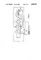
- FIG. 1is a general layout of a foreign object ingestion detection device in operative combination with an exhaust detection device as applied to gas turbine jet engines.
- FIG. 2is a diagram of a laboratory unit for determining the charge of particles passing an intake sensor or probe system.
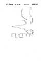
- FIG. 3is a chart showing a typical charge signal from a small stone sensed in the apparatus of FIG. 2.
- FIG. 4is a diagram of a simulated engine for sensing the ingestion of foreign objects.
- FIG. 5is a signal trace of an object sensed in the apparatus of FIG. 4.
- FIGS. 6 and 7depict a sensor configuration suitable for use with the present invention.
- FIG. 8shows the manner of affixing a sensor to the casing of a jet engine.
- FIG. 9is a perspective of a plurality of sensors arranged around the exhaust of a jet engine.
- FIG. 10is a block diagram of a sensing circuit in accordance with the present invention.
- FIG. 11is a block diagram of a circuit relevant to the block diagram of FIG. 10.
- a jet engine indicatedgenerally has an intake 11 and a hot exhaust 12 with a by-pass 13 between intake 11 and exhaust 12.
- the intake of the enginecomprises a duct having a substantially circular internal surface having a circumferential intake sensor 14 comprising four segmental sensor elements, each of which has been mounted onto the internal surface of the intake duct 11.
- Each of the segmental sensorscomprises an insulating layer of epoxy resin of the order of 0.5 mm thick together with a charge collecting layer applied thereover of silver loaded epoxy resin of approximately 0.05 mm in thickness.
- Each of the charge collecting layersis provided with an electrical connector comprising a central cylindrical stud having a flanged head adapted to engage the conductive layer of each sensor with the stud passing through the wall of the intaked duct via an insulating grommet for connection to an intake signal conditioning unit indicated generally at 15.
- a similar peripheral sensor system 17is provided within by pass 13 and is coupled to by pass signal conditioning means 18 which is connected to a signal processing station indicated generally at 20.
- the exhaust duct 12carries four segmental sensors 21 circumferentially disposed about the internal surface of the exhaust duct and electrically connected to signal conditioning means 22 which in turn is also connected to signal processor 20.
- the sensors 21 in the exhaust duct of the engineare in accordance with anyone of Examples 1, 2 or 3 of our co-pending Application No. 8702553.
- the signal processing means 20further has input data 24 from the engine and flight data 24 provided from aircraft flight data from other on board systems.
- the signal processor 20provides a plurality of outputs 25 to an event recorder 26 which records events for subsequent analysis at the completion of the flight regime for the engine.
- An alarm detector 27may also be coupled to processor 20 for any significant incidence to be drawn to the attention of the flight crew.
- a centrifugal suction rig 40was disposed with an outwardly directed inlet 41 and a substantially horizontal lower outlet 41a.
- the inlet 41was provided with an upstanding cylindrical tube 42 constituting an inlet duct.
- the tube 42was provided towards its lower end 43 with an annular ring of circumferential segments 44 disposed on the internal surface and formed by an insulating layer of epoxy resin and a conductive layer of silver loaded epoxy resin of thickness dimensions substantially as described above.
- the inlet tube 42was of substantially 150 mm internal diameter and had a length of approximately 400 mm.
- the upper end 45is juxtaposed an inclinable plate 46, the angle of inclination of which can be adjusted.
- Articles of debris 47are located on the upper surface of inclined plate 46 and released one at a time or in groups into the inlet end 45 of inlet tube 42.
- FIG. 3is the charge signal for a stone of nominal diameter of 6 mm.
- FIG. 4is test bench arrangement to demonstrate the present invention.
- the benchcomprises an air intake 61 debouching into a debris separator 62.
- the debris separatoris connected with combustor 63 which exhausts into a polouche 64 and debouches into a exhaust 65.
- the inlet 61is provided with an inlet mouth 66 in juxtaposition with a turntable assembly 67.
- a debris acceleratorcomprises a conduit 68, a branch of which 69 communicates with polouche 64 to provide a by-pass working section 70.
- the intake 61is provided with three sensors 71, 72 and 73 each of different construction to enable relative tests on the efficiency of different sensors and materials to be evaluated.
- the sensorsare provided with signal conditioning means juxtaposed each sensor and the condition signals fed by means of conductors 74 passing through cable duct 75 to a control room 76 where the signals are monitored and recorded.
- the combustor 63is ignited by the supply of fuel within the combustion ducts 63. Air is drawn into the system by means of inlet 66 and additional air is drawn through debris accelerator tube 68 and by-pass 69 to reproduce the general conditions within a jet engine.
- the turntable assemblyis adjustable and enables selected components or solid items to be ingested into the engine and duct to be presented to inlet 66 so that its passage past sensors 71, 72 and 73 may be monitored by means of the signals induced in each of the sensors.
- sensor 71comprised an insulated layer of flexible epoxy 25 mm wide, a conducting layer of silver loaded epoxy 13 mm wide and a top insulayer of flexible epoxy 25 mm wide.
- Sensors 72 and 73each comprise an insulating layer of flexible polymer material, a conductive layer of silver loaded epoxy and a top insulating layer of a flexible polymer material. The overall dimensions of all three sensors were identical.
- the lead-out connection to the signal conditioningwas effected using a cable which is bonded to the conductive layer employing a conductive epoxy. Individual signal conditioning units are operatively connected with each sensor on the intake working section.
- Debrisis injected into the intake working section using the turntable assembly to simulators realistically as possible ingestion of the article into a jet engine intake, such as will be caused by the effect of thrust or reverse thrust of a jet engine. Debris is collected in the debris separator to ensure that the test engine is not damaged.
- FIG. 5shows a typical signal from this test facility caused by a bolt passing through the intake section.
- FIG. 9A typical series of probes as arranged in the exhaust gas duct of a jet engine is shown in FIG. 9 and two different perspective views of an individual probe are shown in FIGS. 6 and 7.
- four segmental probesare employed to define a segmented rig sensor in the engine's exhaust duct 100.
- Each probecomprises an arcuate plate 114 having a pair of arcuately spaced holes 115.
- the face 116 of plate 114is polished to provide a charge receiving surface and the periphery 117 and the back 118 (see FIG. 7) are covered with a coating of a ceramic, electrically insulating material.
- Each plate 114is secured to the engine casing 120 by means of a securing stud assembly 121.
- the securing stud assemblyis shown in FIG. 8 and comprises a generally cylindrical sleeve 122 which defines on its internal surface towards a first end 124 thereof a constriction 123.
- the external surface of the first end 124is threaded and the second end 125 of stud assembly 121 is provided with an annular recess (not shown).
- the second endis adapted to accommodate an insulating member 126 formed of a ceramic material and having a central bore arranged to accommodate a metal screw 127 which is secured by nut 128 to the ceramic member 126.
- Screw 127is provided with an enlarged slot 130 at its threaded end and is adapted to receive a flattened portion 131 of a stud 132.
- the stud 132is generally cylindrical and is threaded at its first end 133.
- the first end 133is arranged to be engaged by nut 134 which serves to clamp a further ceramic block 135 between the shoulder 136 defined by constriction 123 against ceramic member 126.
- the head 129 of bolt 127serves to retain plate 114 in closely spaced relationship with the casing, but insulated therefrom while the bolt 127 and its associated stud 132 serves to provide a means of electrical connection to the face 116 of plate 114 whereby the end 133 can be electrically connected to a conductor for connection to detection sensing and analytical equipment.
- the ring probesmay also be used in conjunction with rod probes which are provided in the turbo fan casing for analysis of any debris present within the turbine casing itself.
- the probes 118are connected via a four way junction box 160 to supply signals to a debris detection unit 161.
- the debris detection unithas a channel corresponding to each ring probe and provides four outputs 162, 163, 164 and 165 each of which are connected to a tape recorder 166 and subsequently to an oscilloscope 167 to provide a visual indication of the output of the components.
- the debris detection unitalso provides an output to a chart recorder 168.
- Rod probes 170are also connected to a debris detection unit 171 and the various outputs 172, 173, 174 and 175 are connected to tape recorder 166 and 167 and are switchable to chart recorder 168.
- the debris detection unit 162is shown in greater detail in FIG. 11 of the accompanying drawings and comprises a current input (transresistance) amplifier A which is an AC coupled amplifier with the gain set by resistor R. (Different types of probe installation require different settings of R) and the probe signal is AC coupled via capacitor 181 to the inverting input (-) of the amplifier A.
- the non-inverting terminalis connected to the engine casing.
- the output signal at 182passes to the input to a differential amplifier B which removes common mode signal present between the engine casing and the equipment earth.
- the output from the differential amplifier Bis a signal representing the rate at which the charge enters or leaves the probe region. This pulse signal is passed to a pulse outlet socket 183 for subsequent processing or tape recording.
- the pulse signalmay also be passed to an integrating stage C, which for a ring probe, the time integral of the pulse signal represents the amount of charge inside the probe.
- This signalis available via a further output 184 as a charge output. While this signal does not have the same physical significance for rod and ring probes, the low pass filtering action for the integrator aids noise and interference removal.
- the integrator Cis selectable between 1 and 10 seconds and this provides a smoothing charge output which can be separately monitored.
Landscapes
- Physics & Mathematics (AREA)
- Chemical & Material Sciences (AREA)
- General Physics & Mathematics (AREA)
- Engineering & Computer Science (AREA)
- Health & Medical Sciences (AREA)
- Life Sciences & Earth Sciences (AREA)
- Analytical Chemistry (AREA)
- Biochemistry (AREA)
- General Health & Medical Sciences (AREA)
- Electrochemistry (AREA)
- Immunology (AREA)
- Pathology (AREA)
- Chemical Kinetics & Catalysis (AREA)
- Combustion & Propulsion (AREA)
- Testing Of Engines (AREA)
- Organic Low-Molecular-Weight Compounds And Preparation Thereof (AREA)
- Ultra Sonic Daignosis Equipment (AREA)
- Control Of Multiple Motors (AREA)
- Vehicle Cleaning, Maintenance, Repair, Refitting, And Outriggers (AREA)
- Medicines Containing Antibodies Or Antigens For Use As Internal Diagnostic Agents (AREA)
- Investigating Or Analyzing Materials By The Use Of Electric Means (AREA)
- Valve-Gear Or Valve Arrangements (AREA)
- Switches With Compound Operations (AREA)
- Arrangement Or Mounting Of Control Devices For Change-Speed Gearing (AREA)
- Cylinder Crankcases Of Internal Combustion Engines (AREA)
- Transition And Organic Metals Composition Catalysts For Addition Polymerization (AREA)
- Gasification And Melting Of Waste (AREA)
Abstract
Description
Claims (9)
Applications Claiming Priority (2)
| Application Number | Priority Date | Filing Date | Title |
|---|---|---|---|
| GB8707187 | 1987-03-25 | ||
| GB878707187AGB8707187D0 (en) | 1987-03-25 | 1987-03-25 | Monitoring of foreign object in engines |
Publications (1)
| Publication Number | Publication Date |
|---|---|
| US4888948Atrue US4888948A (en) | 1989-12-26 |
Family
ID=10614662
Family Applications (1)
| Application Number | Title | Priority Date | Filing Date |
|---|---|---|---|
| US07/171,683Expired - LifetimeUS4888948A (en) | 1987-03-25 | 1988-03-22 | Monitoring of foreign object ingestion in engines |
Country Status (13)
| Country | Link |
|---|---|
| US (1) | US4888948A (en) |
| EP (1) | EP0284392B1 (en) |
| JP (1) | JP2864125B2 (en) |
| AT (1) | ATE112056T1 (en) |
| AU (1) | AU605564B2 (en) |
| CA (1) | CA1282136C (en) |
| DE (2) | DE3851559D1 (en) |
| DK (1) | DK162888A (en) |
| GB (1) | GB8707187D0 (en) |
| IL (1) | IL85857A (en) |
| IN (1) | IN171024B (en) |
| NO (1) | NO881262L (en) |
| ZA (1) | ZA882149B (en) |
Cited By (35)
| Publication number | Priority date | Publication date | Assignee | Title |
|---|---|---|---|---|
| US5622045A (en)* | 1995-06-07 | 1997-04-22 | Allison Engine Company, Inc. | System for detecting and accommodating gas turbine engine fan damage |
| GB2335745A (en)* | 1998-03-27 | 1999-09-29 | Pcme Limited | Improvements in and relating to particle detectors |
| DE10207455A1 (en)* | 2002-02-22 | 2003-09-18 | Framatome Anp Gmbh | Method and device for detecting a pulse-like mechanical action on a plant part |
| US6668655B2 (en) | 2001-09-27 | 2003-12-30 | Siemens Westinghouse Power Corporation | Acoustic monitoring of foreign objects in combustion turbines during operation |
| US20040055900A1 (en)* | 2002-09-23 | 2004-03-25 | Siemens Westinghouse Power Corporation | Apparatus and methods for sampling and analyzing inlet air associated with combustion turbine |
| US20060016246A1 (en)* | 2003-12-31 | 2006-01-26 | Honeywell International Inc. | Pariculate-based flow sensor |
| US20080042655A1 (en)* | 2006-07-07 | 2008-02-21 | Univation Technologies, Llc | Systems and methods for detecting impurities in reactor systems |
| US20080288187A1 (en)* | 2006-02-03 | 2008-11-20 | Areva Np Gmbh | Method and Device for Detecting the Location of a Pulse-Type Mechanical Effect on a System Part |
| US20090048791A1 (en)* | 2006-02-03 | 2009-02-19 | Areva Np Gmbh | Method and Device for Detecting a Pulse-Type Mechanical Effect on a System Part |
| US20090306829A1 (en)* | 2006-10-11 | 2009-12-10 | Hildebrand Steve F | Aircraft with transient-discriminating propeller balancing system |
| US20100292905A1 (en)* | 2009-05-18 | 2010-11-18 | Agrawal Rajendra K | System and method of estimating gas turbine engine performance |
| US20100287907A1 (en)* | 2009-05-18 | 2010-11-18 | Agrawal Rajendra K | System and method of estimating a gas turbine engine surge margin |
| US20100288034A1 (en)* | 2009-05-18 | 2010-11-18 | Agrawal Rajendra K | System and method of assessing thermal energy levels of a gas turbine engine component |
| US20100313639A1 (en)* | 2009-06-11 | 2010-12-16 | Khibnik Alexander I | Gas turbine engine debris monitoring arrangement |
| US20110041474A1 (en)* | 2009-08-21 | 2011-02-24 | Snecma | Method and system for detecting the ingestion of an object by an aircraft turbine engine during a mission |
| US20110095912A1 (en)* | 2009-06-19 | 2011-04-28 | Fred Charles Sands | Jet engine protection system |
| US20110179763A1 (en)* | 2007-03-28 | 2011-07-28 | United Technologies Corporation | Particle separator and debris control system |
| US20120063879A1 (en)* | 2009-07-21 | 2012-03-15 | Veilleux Jr Leo J | Energy efficient ips blower assembly |
| US20130025348A1 (en)* | 2011-07-29 | 2013-01-31 | Ravi Rajamani | Aircraft debris monitoring sensor assembly |
| CN103063437A (en)* | 2013-01-14 | 2013-04-24 | 南京航空航天大学 | Simulation experiment device for aero-engine suction object on-line static monitoring system |
| US8459103B2 (en) | 2011-06-24 | 2013-06-11 | United Technologies Corporation | IDMS signal processing to distinguish inlet particulates |
| FR2997499A1 (en)* | 2012-10-31 | 2014-05-02 | Snecma | Method for testing ingestion of projectile i.e. bird, by e.g. turbojet, of aircraft, involves actuating temporary connection to obtain dissociation of projectile from support such that projectile is sucked by fluid flow during operation |
| WO2014138432A1 (en)* | 2013-03-06 | 2014-09-12 | United Technologies Corporation | Oil system debris monitor system for a gas turbine engine |
| US20150152743A1 (en)* | 2012-07-25 | 2015-06-04 | Siemens Aktiengesellschaft | Method for minimizing the gap between a rotor and a housing |
| US9366154B2 (en) | 2010-02-08 | 2016-06-14 | Snecma | Method for the automated detection of the ingestion of at least one foreign body by a gas turbine engine |
| US20160195411A1 (en)* | 2014-11-06 | 2016-07-07 | United Technologies Corporation | Encapsulated Soft-Lead Capacitance Probe for a Gas Turbine Engine |
| US9631554B2 (en) | 2014-01-14 | 2017-04-25 | Honeywell International Inc. | Electrostatic charge control inlet particle separator system |
| US9714967B1 (en) | 2016-01-27 | 2017-07-25 | General Electric Company | Electrostatic dust and debris sensor for an engine |
| CN108120602A (en)* | 2017-12-11 | 2018-06-05 | 南京航空航天大学 | A kind of aero-engine air intake duct sand dust inhalation (inhalatio) electrostatic monitoring experimental bench |
| US10073008B2 (en) | 2016-01-27 | 2018-09-11 | General Electric Company | Electrostatic sensor |
| US20180298778A1 (en)* | 2017-04-18 | 2018-10-18 | Honeywell International Inc. | Gas turbine engine particulate ingestion and accumulation sensor system and method |
| US10845294B1 (en)* | 2019-07-03 | 2020-11-24 | Raytheon Technologies Corporation | Systems and methods for particulate ingestion sensing in gas turbine engines |
| US11149583B2 (en) | 2017-04-18 | 2021-10-19 | Honeywell International Inc. | Gas turbine engine particulate ingestion and accumulation sensor system and method |
| US11492967B2 (en) | 2019-07-03 | 2022-11-08 | Raytheon Technologies Corporation | Particulate ingestion sensor for gas turbine engines |
| US20250179934A1 (en)* | 2023-12-01 | 2025-06-05 | Rolls-Royce Plc | Method for reducing damage to components of gas turbine engines |
Families Citing this family (9)
| Publication number | Priority date | Publication date | Assignee | Title |
|---|---|---|---|---|
| GB8901238D0 (en)* | 1989-01-20 | 1989-03-15 | Stewart Hughes Ltd | Improvements relating to charge sensors |
| GB9025815D0 (en)* | 1990-11-28 | 1991-01-09 | Stewart Hughes Ltd | Fluid debris monitoring |
| US5760298A (en)* | 1990-11-28 | 1998-06-02 | Stewart Hughes Ltd. | System and method for monitoring debris in a fluid |
| GB0126706D0 (en) | 2001-11-07 | 2002-01-02 | Rolls Royce Plc | An apparatus and method for detecting an impact on a rotor blade |
| GB0410778D0 (en)* | 2004-05-13 | 2004-06-16 | Rolls Royce Plc | Blade arrangement |
| WO2008045080A1 (en)* | 2006-10-12 | 2008-04-17 | United Technologies Corporation | Variable area fan nozzle for accommodating a foreign object strike event |
| GB2482480A (en)* | 2010-08-02 | 2012-02-08 | Lockheed Martin Uk Insys Ltd | An electrostatic particle ingress inhibitor |
| US11125168B2 (en)* | 2018-10-24 | 2021-09-21 | Raytheon Technologies Corporation | Dirt mitigation in a gas turbine engine |
| US11261800B2 (en) | 2018-10-24 | 2022-03-01 | Raytheon Technologies Corporation | Adaptive bleed schedule in a gas turbine engine |
Citations (5)
| Publication number | Priority date | Publication date | Assignee | Title |
|---|---|---|---|---|
| US2994035A (en)* | 1954-12-16 | 1961-07-25 | Feifel Eugen | Apparatus for determining the dust content of gases or vapors |
| US3784902A (en)* | 1971-12-08 | 1974-01-08 | Ikor Inc | Apparatus for sensing particulate matter |
| US4312180A (en)* | 1979-09-28 | 1982-01-26 | Battelle Development Corporation | Detecting particles |
| US4607228A (en)* | 1984-01-13 | 1986-08-19 | Battelle Development Corporation | Apparatus and method for measuring the concentration of solid particles in a fluid stream |
| US4631482A (en)* | 1984-10-09 | 1986-12-23 | Auburn International, Inc. | Dust flow inducing monitor |
Family Cites Families (6)
| Publication number | Priority date | Publication date | Assignee | Title |
|---|---|---|---|---|
| US256845A (en)* | 1882-04-25 | Hale to thomas m | ||
| AU4117672A (en)* | 1971-04-15 | 1973-10-18 | Fielden Electronics Limited | Improvements in or relating to flow detection |
| US4584531A (en)* | 1982-10-04 | 1986-04-22 | United Technologies Corporation | Noncontact electrostatic hoop probe for combustion engines |
| US4456883A (en)* | 1982-10-04 | 1984-06-26 | Ambac Industries, Incorporated | Method and apparatus for indicating an operating characteristic of an internal combustion engine |
| US4607337A (en)* | 1982-12-28 | 1986-08-19 | United Technologies Corporation | Interprobe electrostatic engine diagnostics correlation |
| EP0256845A2 (en)* | 1986-08-20 | 1988-02-24 | Stewart Hughes Limited | Jet engine gas path condition monitoring |
- 1987
- 1987-03-25GBGB878707187Apatent/GB8707187D0/enactivePending
- 1988
- 1988-03-22USUS07/171,683patent/US4888948A/ennot_activeExpired - Lifetime
- 1988-03-22NONO881262Apatent/NO881262L/enunknown
- 1988-03-23ININ188/MAS/88Apatent/IN171024B/enunknown
- 1988-03-24ILIL85857Apatent/IL85857A/ennot_activeIP Right Cessation
- 1988-03-24DEDE3851559Apatent/DE3851559D1/ennot_activeExpired - Fee Related
- 1988-03-24ATAT88302618Tpatent/ATE112056T1/ennot_activeIP Right Cessation
- 1988-03-24DKDK162888Apatent/DK162888A/ennot_activeApplication Discontinuation
- 1988-03-24DEDE3851559Tpatent/DE3851559T4/ennot_activeExpired - Lifetime
- 1988-03-24CACA000562340Apatent/CA1282136C/ennot_activeExpired - Lifetime
- 1988-03-24EPEP88302618Apatent/EP0284392B1/ennot_activeExpired - Lifetime
- 1988-03-24AUAU13594/88Apatent/AU605564B2/ennot_activeCeased
- 1988-03-25JPJP63069918Apatent/JP2864125B2/ennot_activeExpired - Lifetime
- 1988-03-25ZAZA882149Apatent/ZA882149B/enunknown
Patent Citations (5)
| Publication number | Priority date | Publication date | Assignee | Title |
|---|---|---|---|---|
| US2994035A (en)* | 1954-12-16 | 1961-07-25 | Feifel Eugen | Apparatus for determining the dust content of gases or vapors |
| US3784902A (en)* | 1971-12-08 | 1974-01-08 | Ikor Inc | Apparatus for sensing particulate matter |
| US4312180A (en)* | 1979-09-28 | 1982-01-26 | Battelle Development Corporation | Detecting particles |
| US4607228A (en)* | 1984-01-13 | 1986-08-19 | Battelle Development Corporation | Apparatus and method for measuring the concentration of solid particles in a fluid stream |
| US4631482A (en)* | 1984-10-09 | 1986-12-23 | Auburn International, Inc. | Dust flow inducing monitor |
Cited By (57)
| Publication number | Priority date | Publication date | Assignee | Title |
|---|---|---|---|---|
| US5622045A (en)* | 1995-06-07 | 1997-04-22 | Allison Engine Company, Inc. | System for detecting and accommodating gas turbine engine fan damage |
| GB2335745A (en)* | 1998-03-27 | 1999-09-29 | Pcme Limited | Improvements in and relating to particle detectors |
| US6489775B1 (en) | 1998-03-27 | 2002-12-03 | Pcme Ltd. | Particle detectors |
| GB2335745B (en)* | 1998-03-27 | 2003-04-09 | Pcme Ltd | Improvements in and relating to particle detectors |
| US6668655B2 (en) | 2001-09-27 | 2003-12-30 | Siemens Westinghouse Power Corporation | Acoustic monitoring of foreign objects in combustion turbines during operation |
| DE10207455B4 (en)* | 2002-02-22 | 2006-04-20 | Framatome Anp Gmbh | Method and device for detecting a pulse-like mechanical action on a plant part |
| DE10207455A1 (en)* | 2002-02-22 | 2003-09-18 | Framatome Anp Gmbh | Method and device for detecting a pulse-like mechanical action on a plant part |
| US20050021267A1 (en)* | 2002-02-22 | 2005-01-27 | Framatome Anp Gmbh | Method and device for detecting a pulse-type mechanical effect on a system part |
| US6907368B2 (en) | 2002-02-22 | 2005-06-14 | Framatome Anp Gmbh | Method and device for detecting a pulse-type mechanical effect on a system part |
| US20040055900A1 (en)* | 2002-09-23 | 2004-03-25 | Siemens Westinghouse Power Corporation | Apparatus and methods for sampling and analyzing inlet air associated with combustion turbine |
| US20060016246A1 (en)* | 2003-12-31 | 2006-01-26 | Honeywell International Inc. | Pariculate-based flow sensor |
| US7275415B2 (en)* | 2003-12-31 | 2007-10-02 | Honeywell International Inc. | Particulate-based flow sensor |
| US20070271903A1 (en)* | 2003-12-31 | 2007-11-29 | Honeywell International Inc. | Particle-based flow sensor |
| US7549317B2 (en) | 2003-12-31 | 2009-06-23 | Honeywell International Inc. | Particle-based flow sensor |
| US20090048791A1 (en)* | 2006-02-03 | 2009-02-19 | Areva Np Gmbh | Method and Device for Detecting a Pulse-Type Mechanical Effect on a System Part |
| US7542860B2 (en) | 2006-02-03 | 2009-06-02 | Areva Np Gmbh | Method and device for detecting the location of a pulse-type mechanical effect on a system part |
| US20080288187A1 (en)* | 2006-02-03 | 2008-11-20 | Areva Np Gmbh | Method and Device for Detecting the Location of a Pulse-Type Mechanical Effect on a System Part |
| US7684951B2 (en) | 2006-02-03 | 2010-03-23 | Areva Np Gmbh | Method and device for detecting a pulse-type mechanical effect on a system part |
| US7808227B2 (en) | 2006-07-07 | 2010-10-05 | Univation Technologies, Llc | Systems and methods for detecting impurities in reactor systems |
| US20080042655A1 (en)* | 2006-07-07 | 2008-02-21 | Univation Technologies, Llc | Systems and methods for detecting impurities in reactor systems |
| WO2008008169A3 (en)* | 2006-07-07 | 2008-04-03 | Univation Tech Llc | Using electrical probes for detecting impurities in reactor systems |
| US20090306829A1 (en)* | 2006-10-11 | 2009-12-10 | Hildebrand Steve F | Aircraft with transient-discriminating propeller balancing system |
| US8360728B2 (en) | 2006-10-11 | 2013-01-29 | Lord Corporation | Aircraft with transient-discriminating propeller balancing system |
| US20110179763A1 (en)* | 2007-03-28 | 2011-07-28 | United Technologies Corporation | Particle separator and debris control system |
| US8424279B2 (en)* | 2007-03-28 | 2013-04-23 | United Technologies Corporation | Particle separator and debris control system |
| US20100292905A1 (en)* | 2009-05-18 | 2010-11-18 | Agrawal Rajendra K | System and method of estimating gas turbine engine performance |
| US20100287907A1 (en)* | 2009-05-18 | 2010-11-18 | Agrawal Rajendra K | System and method of estimating a gas turbine engine surge margin |
| US20100288034A1 (en)* | 2009-05-18 | 2010-11-18 | Agrawal Rajendra K | System and method of assessing thermal energy levels of a gas turbine engine component |
| US8074498B2 (en) | 2009-05-18 | 2011-12-13 | United Technologies Corporation | System and method of assessing thermal energy levels of a gas turbine engine component |
| US8204671B2 (en) | 2009-05-18 | 2012-06-19 | United Technologies Corporation | System and method of estimating gas turbine engine performance |
| US20100313639A1 (en)* | 2009-06-11 | 2010-12-16 | Khibnik Alexander I | Gas turbine engine debris monitoring arrangement |
| EP2273075A3 (en)* | 2009-06-11 | 2014-07-02 | United Technologies Corporation | Method and apparatus for monitoring debris in a gas turbine engine |
| US8256277B2 (en) | 2009-06-11 | 2012-09-04 | United Technologies Corporation | Gas turbine engine debris monitoring arrangement |
| US20110095912A1 (en)* | 2009-06-19 | 2011-04-28 | Fred Charles Sands | Jet engine protection system |
| US8052767B2 (en)* | 2009-06-19 | 2011-11-08 | Vintage Capital Group, Llc | Jet engine protection system |
| US20120063879A1 (en)* | 2009-07-21 | 2012-03-15 | Veilleux Jr Leo J | Energy efficient ips blower assembly |
| US8528317B2 (en)* | 2009-08-21 | 2013-09-10 | Snecma | Method and system for detecting the ingestion of an object by an aircraft turbine engine during a mission |
| US20110041474A1 (en)* | 2009-08-21 | 2011-02-24 | Snecma | Method and system for detecting the ingestion of an object by an aircraft turbine engine during a mission |
| US9366154B2 (en) | 2010-02-08 | 2016-06-14 | Snecma | Method for the automated detection of the ingestion of at least one foreign body by a gas turbine engine |
| US8459103B2 (en) | 2011-06-24 | 2013-06-11 | United Technologies Corporation | IDMS signal processing to distinguish inlet particulates |
| US9010198B2 (en)* | 2011-07-29 | 2015-04-21 | United Technologies Corporation | Aircraft debris monitoring sensor assembly |
| US20130025348A1 (en)* | 2011-07-29 | 2013-01-31 | Ravi Rajamani | Aircraft debris monitoring sensor assembly |
| US20150152743A1 (en)* | 2012-07-25 | 2015-06-04 | Siemens Aktiengesellschaft | Method for minimizing the gap between a rotor and a housing |
| FR2997499A1 (en)* | 2012-10-31 | 2014-05-02 | Snecma | Method for testing ingestion of projectile i.e. bird, by e.g. turbojet, of aircraft, involves actuating temporary connection to obtain dissociation of projectile from support such that projectile is sucked by fluid flow during operation |
| CN103063437A (en)* | 2013-01-14 | 2013-04-24 | 南京航空航天大学 | Simulation experiment device for aero-engine suction object on-line static monitoring system |
| WO2014138432A1 (en)* | 2013-03-06 | 2014-09-12 | United Technologies Corporation | Oil system debris monitor system for a gas turbine engine |
| US9631554B2 (en) | 2014-01-14 | 2017-04-25 | Honeywell International Inc. | Electrostatic charge control inlet particle separator system |
| US10436612B2 (en)* | 2014-11-06 | 2019-10-08 | United Technologies Corporation | Encapsulated soft-lead capacitance probe for a gas turbine engine |
| US20160195411A1 (en)* | 2014-11-06 | 2016-07-07 | United Technologies Corporation | Encapsulated Soft-Lead Capacitance Probe for a Gas Turbine Engine |
| US9714967B1 (en) | 2016-01-27 | 2017-07-25 | General Electric Company | Electrostatic dust and debris sensor for an engine |
| US10073008B2 (en) | 2016-01-27 | 2018-09-11 | General Electric Company | Electrostatic sensor |
| US20180298778A1 (en)* | 2017-04-18 | 2018-10-18 | Honeywell International Inc. | Gas turbine engine particulate ingestion and accumulation sensor system and method |
| US11149583B2 (en) | 2017-04-18 | 2021-10-19 | Honeywell International Inc. | Gas turbine engine particulate ingestion and accumulation sensor system and method |
| CN108120602A (en)* | 2017-12-11 | 2018-06-05 | 南京航空航天大学 | A kind of aero-engine air intake duct sand dust inhalation (inhalatio) electrostatic monitoring experimental bench |
| US10845294B1 (en)* | 2019-07-03 | 2020-11-24 | Raytheon Technologies Corporation | Systems and methods for particulate ingestion sensing in gas turbine engines |
| US11492967B2 (en) | 2019-07-03 | 2022-11-08 | Raytheon Technologies Corporation | Particulate ingestion sensor for gas turbine engines |
| US20250179934A1 (en)* | 2023-12-01 | 2025-06-05 | Rolls-Royce Plc | Method for reducing damage to components of gas turbine engines |
Also Published As
| Publication number | Publication date |
|---|---|
| AU1359488A (en) | 1988-09-29 |
| JPS63253124A (en) | 1988-10-20 |
| JP2864125B2 (en) | 1999-03-03 |
| IL85857A (en) | 1993-02-21 |
| DE3851559T4 (en) | 1995-06-14 |
| DK162888A (en) | 1988-09-26 |
| EP0284392A3 (en) | 1990-01-31 |
| DE3851559T2 (en) | 1995-02-02 |
| ATE112056T1 (en) | 1994-10-15 |
| IN171024B (en) | 1992-07-04 |
| NO881262D0 (en) | 1988-03-22 |
| EP0284392A2 (en) | 1988-09-28 |
| GB8707187D0 (en) | 1987-04-29 |
| EP0284392B1 (en) | 1994-09-21 |
| DK162888D0 (en) | 1988-03-24 |
| AU605564B2 (en) | 1991-01-17 |
| NO881262L (en) | 1988-09-26 |
| ZA882149B (en) | 1989-02-22 |
| CA1282136C (en) | 1991-03-26 |
| DE3851559D1 (en) | 1994-10-27 |
| IL85857A0 (en) | 1988-09-30 |
Similar Documents
| Publication | Publication Date | Title |
|---|---|---|
| US4888948A (en) | Monitoring of foreign object ingestion in engines | |
| EP0110802B1 (en) | Method and apparatus for indicating an operating characteristic of an internal combustion engine | |
| AU2012291824B2 (en) | Sensing systems | |
| US5442285A (en) | NDE eddy current sensor for very high scan rate applications in an operating combustion turbine | |
| US5214386A (en) | Apparatus and method for measuring particles in polydispersed systems and particle concentrations of monodispersed aerosols | |
| EP0120087B1 (en) | Noncontact electrostatic hoop probe for combustion engines | |
| EP0256845A2 (en) | Jet engine gas path condition monitoring | |
| EP0671001B1 (en) | A sensor | |
| Farr | Evaluation of F-15 inlet dynamic distortion | |
| Gajewski | Measuring probes, head, and system for the non-contact, electrostatic measurements of the two-phase flow parameters in pneumatic transport of solids | |
| SU591050A1 (en) | Electrostatic probe | |
| Schlemper et al. | Sensitivity of acoustic PD detection in GIS. Laboratory experiments and on-site experience | |
| SU661349A1 (en) | Electrostatic probe | |
| US4286209A (en) | Small conductive particle sensor | |
| CN111121948B (en) | Method for detecting vibration characteristic of air handling unit | |
| CN110793893A (en) | Charge induction dust concentration detection device | |
| Taback | Small conductive particle sensor | |
| AU680999B2 (en) | System and method for monitoring the quality of a fluid | |
| Cole et al. | The Design, Fabrication and Field Testing of a Gas Particle Velocity Sensor. | |
| Velkoff et al. | Investigation of Electrostatic Charge Action in Liquids for Use in Detection of Cavitation |
Legal Events
| Date | Code | Title | Description |
|---|---|---|---|
| AS | Assignment | Owner name:STEWART HUGHES LIMITED, CHILWORTH MANOR, SOUTHAMPT Free format text:ASSIGNMENT OF ASSIGNORS INTEREST.;ASSIGNORS:FISHER, CELIA E.;FORFITT, ROY;REEL/FRAME:004856/0187 Effective date:19880316 Owner name:STEWART HUGHES LIMITED, A BRITISH COMPANY,UNITED K Free format text:ASSIGNMENT OF ASSIGNORS INTEREST;ASSIGNORS:FISHER, CELIA E.;FORFITT, ROY;REEL/FRAME:004856/0187 Effective date:19880316 | |
| STCF | Information on status: patent grant | Free format text:PATENTED CASE | |
| FPAY | Fee payment | Year of fee payment:4 | |
| FPAY | Fee payment | Year of fee payment:8 | |
| FEPP | Fee payment procedure | Free format text:PAT HLDR NO LONGER CLAIMS SMALL ENT STAT AS SMALL BUSINESS (ORIGINAL EVENT CODE: LSM2); ENTITY STATUS OF PATENT OWNER: LARGE ENTITY | |
| REFU | Refund | Free format text:REFUND - PAYMENT OF MAINTENANCE FEE, 12TH YR, SMALL ENTITY (ORIGINAL EVENT CODE: R285); ENTITY STATUS OF PATENT OWNER: LARGE ENTITY | |
| FPAY | Fee payment | Year of fee payment:12 | |
| SULP | Surcharge for late payment | Year of fee payment:11 |