US4888795A - Videotelephone apparatus for transmitting high and low resolution video signals over telephone exchange lines - Google Patents
Videotelephone apparatus for transmitting high and low resolution video signals over telephone exchange linesDownload PDFInfo
- Publication number
- US4888795A US4888795AUS07/212,498US21249888AUS4888795AUS 4888795 AUS4888795 AUS 4888795AUS 21249888 AUS21249888 AUS 21249888AUS 4888795 AUS4888795 AUS 4888795A
- Authority
- US
- United States
- Prior art keywords
- signal
- frame
- display
- high resolution
- videotelephone
- Prior art date
- Legal status (The legal status is an assumption and is not a legal conclusion. Google has not performed a legal analysis and makes no representation as to the accuracy of the status listed.)
- Expired - Lifetime
Links
- 230000015654memoryEffects0.000claimsabstractdescription94
- 230000005540biological transmissionEffects0.000claimsabstractdescription42
- 230000004044responseEffects0.000claimsabstractdescription37
- 238000009432framingMethods0.000claimsdescription37
- 238000006243chemical reactionMethods0.000claimsdescription31
- 230000008878couplingEffects0.000claimsdescription25
- 238000010168coupling processMethods0.000claimsdescription25
- 238000005859coupling reactionMethods0.000claimsdescription25
- 238000013144data compressionMethods0.000claimsdescription25
- 239000003550markerSubstances0.000claimsdescription14
- 238000013139quantizationMethods0.000claimsdescription6
- 238000001514detection methodMethods0.000claimsdescription3
- 230000006837decompressionEffects0.000claims1
- 239000011159matrix materialSubstances0.000abstractdescription15
- 238000004891communicationMethods0.000abstractdescription13
- 238000000034methodMethods0.000description23
- 238000010586diagramMethods0.000description20
- 230000008569processEffects0.000description18
- 238000012545processingMethods0.000description11
- 230000009977dual effectEffects0.000description9
- 230000003111delayed effectEffects0.000description6
- 238000005070samplingMethods0.000description6
- 238000012935AveragingMethods0.000description3
- 230000015556catabolic processEffects0.000description2
- 238000006731degradation reactionMethods0.000description2
- 230000008014freezingEffects0.000description2
- 238000007710freezingMethods0.000description2
- 230000006870functionEffects0.000description2
- 238000012986modificationMethods0.000description2
- 230000004048modificationEffects0.000description2
- 230000001360synchronised effectEffects0.000description2
- 241000872198Serjania polyphyllaSpecies0.000description1
- 230000004075alterationEffects0.000description1
- 230000001174ascending effectEffects0.000description1
- 230000008901benefitEffects0.000description1
- 239000003086colorantSubstances0.000description1
- 238000012790confirmationMethods0.000description1
- 230000001934delayEffects0.000description1
- 230000000994depressogenic effectEffects0.000description1
- 238000013461designMethods0.000description1
- 230000000694effectsEffects0.000description1
- 238000002474experimental methodMethods0.000description1
- 239000004973liquid crystal related substanceSubstances0.000description1
- 230000000737periodic effectEffects0.000description1
- 230000000750progressive effectEffects0.000description1
- 230000008054signal transmissionEffects0.000description1
- 230000002123temporal effectEffects0.000description1
- 238000012546transferMethods0.000description1
- 230000009466transformationEffects0.000description1
Images


Classifications
- H—ELECTRICITY
- H04—ELECTRIC COMMUNICATION TECHNIQUE
- H04N—PICTORIAL COMMUNICATION, e.g. TELEVISION
- H04N7/00—Television systems
- H04N7/14—Systems for two-way working
- H04N7/141—Systems for two-way working between two video terminals, e.g. videophone
- H04N7/142—Constructional details of the terminal equipment, e.g. arrangements of the camera and the display
- H—ELECTRICITY
- H04—ELECTRIC COMMUNICATION TECHNIQUE
- H04N—PICTORIAL COMMUNICATION, e.g. TELEVISION
- H04N1/00—Scanning, transmission or reproduction of documents or the like, e.g. facsimile transmission; Details thereof
- H04N1/32—Circuits or arrangements for control or supervision between transmitter and receiver or between image input and image output device, e.g. between a still-image camera and its memory or between a still-image camera and a printer device
- H04N1/333—Mode signalling or mode changing; Handshaking therefor
- H04N1/33307—Mode signalling or mode changing; Handshaking therefor prior to start of transmission, input or output of the picture signal only
- H—ELECTRICITY
- H04—ELECTRIC COMMUNICATION TECHNIQUE
- H04N—PICTORIAL COMMUNICATION, e.g. TELEVISION
- H04N19/00—Methods or arrangements for coding, decoding, compressing or decompressing digital video signals
- H—ELECTRICITY
- H04—ELECTRIC COMMUNICATION TECHNIQUE
- H04N—PICTORIAL COMMUNICATION, e.g. TELEVISION
- H04N7/00—Television systems
- H04N7/12—Systems in which the television signal is transmitted via one channel or a plurality of parallel channels, the bandwidth of each channel being less than the bandwidth of the television signal
- H04N7/122—Systems in which the television signal is transmitted via one channel or a plurality of parallel channels, the bandwidth of each channel being less than the bandwidth of the television signal involving expansion and subsequent compression of a signal segment, e.g. a frame, a line
- H—ELECTRICITY
- H04—ELECTRIC COMMUNICATION TECHNIQUE
- H04N—PICTORIAL COMMUNICATION, e.g. TELEVISION
- H04N19/00—Methods or arrangements for coding, decoding, compressing or decompressing digital video signals
- H04N19/30—Methods or arrangements for coding, decoding, compressing or decompressing digital video signals using hierarchical techniques, e.g. scalability
- H—ELECTRICITY
- H04—ELECTRIC COMMUNICATION TECHNIQUE
- H04N—PICTORIAL COMMUNICATION, e.g. TELEVISION
- H04N19/00—Methods or arrangements for coding, decoding, compressing or decompressing digital video signals
- H04N19/60—Methods or arrangements for coding, decoding, compressing or decompressing digital video signals using transform coding
- Y—GENERAL TAGGING OF NEW TECHNOLOGICAL DEVELOPMENTS; GENERAL TAGGING OF CROSS-SECTIONAL TECHNOLOGIES SPANNING OVER SEVERAL SECTIONS OF THE IPC; TECHNICAL SUBJECTS COVERED BY FORMER USPC CROSS-REFERENCE ART COLLECTIONS [XRACs] AND DIGESTS
- Y10—TECHNICAL SUBJECTS COVERED BY FORMER USPC
- Y10S—TECHNICAL SUBJECTS COVERED BY FORMER USPC CROSS-REFERENCE ART COLLECTIONS [XRACs] AND DIGESTS
- Y10S379/00—Telephonic communications
- Y10S379/916—Touch screen associated with telephone set
Definitions
- This inventionrelates generally to audiovisual communication systems and, in particular, to a videotelephone apparatus for transmitting low frame rate video signals over telephone exchange lines.
- Bell System's "Picturephone”is a typical example of audiovisual communication system. Because of the wide bandwidth, the prior art system is intended for use with a wideband, dedicated transmission line. It has therefore been desired to implement an audiovisual communication system having a bandwidth within the range of frequencies of telephone exchange lines. It has been further desired to implement a system which simultaneously performs face-to-face communications and document transmission.
- Another object of the present inventionis to provide a videotelephone apparatus which can be used advantageously with ISDN (Integrated Services Digital Network) exchange lines.
- ISDNIntegrated Services Digital Network
- a first high frame rate video signalis derived from an image containing moving objects and a second high frame rate video signal is derived from an image containing standstill objects.
- the first high frame rate video signalis converted to a low frame rate low resolution multiframe signal and the second high frame rate video signal is converted to a single frame high resolution signal.
- the low frame rate low resolution signalis transmitted at a rate of five frames per second and the single frame high resolution signal is transmitted during the interval of 1 to 4 seconds.
- Each frame of the low resolution signalhas nxm pixels, typically 80 ⁇ 60 pixels and the frame of the high resolution signal has N ⁇ M pixels, or 320 ⁇ 240 pixels.
- both low and high resolution signalsare within the range of frequencies of a telephone exchange line.
- a switching matrixis provided to sequentially couple the low frame rate low resolution signal and the single frame high resolution signal to a transmission line in response to a mode select signal and couple the exchange line to a display unit.
- the single frame high resolution signalis stored into a memory and repeatedly read out of the memory into a display.
- the second high frame rate video signal that conveys the image of a documentis first converted to a multiframe high resolution signal and the latter is then converted to the single frame high resolution signal.
- Manually operated command keysare provided to generate a framing command signal and a document transmit command signal during face-to-face communications.
- the switching matrixcouples the multiframe high resolution signal to the display to allow the user to adjust the position of a document so that it comes into the field of view.
- the low resolution signalis disconnected from the transmission line to allow transmission of the single frame high resolution signal to the distant end while switching the display input from the multiframe high resolution signal to the transmitted single frame high resolution signal to allow the source viewer to monitor the freeze frame image of the document actually transmitted.
- the display unitpreferably includes a frame memory to retain the frame of a received low resolution signal which has been received just prior to the reception of a single frame high resolution signal to keep the last frame on display when it is interrupted during the transmission of the single frame high resolution signal.
- a still picture detectoris preferably provided which responds to the framing command signal for detecting a still motion in the high resolution multiframe signal.
- the switching matrixresponds to the detection of a still motion and couples the single frame high resolution signal to the exchange line for transmission to the other party and to the display for confirmation.
- two flat panel displays respectively having nxm and N ⁇ M pixelsare mounted on a rear, higher profile portion of a housing, with the nxm pixel display being located in a position higher than the N ⁇ M pixel display.
- an N ⁇ M pixel flat panel displaymay be provided instead of two displays to provide both low and high resolution images in an individual or superimposed mode.
- An image enlarging circuitis advantageously provided for multiplying each pixel of a received low frame rate low resolution signal by a factor N ⁇ M/nxm to display the received signal on the (N ⁇ M) pixel display.
- a screen touch sensorfor supplying a coordinate signal indicating a point specified on the N ⁇ M pixel display unit in a coordinate system to a marker generator which transmits a marker code in response to the coordinate signal to the transmission line.
- a pivoted armis provided on the housing, the arm being movable between a rest position in the housing and an upright position.
- a video camerais mounted at the free end of the arm to pick up the user's own face when the arm is in the rest position and pick up a document when the arm is in the upright position.
- a switchis located adjacent the pivot point of the arm to generate a framing command signal when the arm is brought to the upright position to cause the switching matrix to automatically switch the input of the display to the high resolution multiframe signal for "framing" the document.
- the first and second high frame rate video signalsare converted by a data compression circuit to a low resolution multiframe signal according to a data compression algorithm and the second high rate video signal is converted to a high resolution single frame signal according to the data compression algorithm.
- a data expansion circuitis provided for converting a received low resolution multiframe signal and a received high resolution single frame signal to signals according to a data expansion algorithm inverse to the data compression algorithm.
- the data compression circuitcomprises first and second coding circuits having a hierarchical coding algorithm.
- the data compression circuitincludes a plurality of spatial frequency filters of different resolutions through which the first and second high frame rate video signals are passed to develop differential video signals of different levels of resolution.
- the differential video signalsare successively transmitted with the lowest level of resolution first and an intermediate level of resolution last when transmitting a low resolution multiframe signal and all the differential video signals are successively transmitted with the lowest level of resolution first and the highest level of resolution last when transmitting a single frame high resolution signal.
- the data compression circuitcomprises a frame memory, a write address generator for writing the first and second video output signals into the frame memory at a frame rate lower than the frame rate of the video output signals.
- a microprocessorwhich performs discrete cosine transform (DCT) on data stored in the frame memory on a block by block basis, performs scaler quantization and performs modified Huffman coding on data stored in a smaller portion of each of the blocks in response to a first control signal from the switching circuit and repeating the previous steps to generate the low frame rate low resolution signal.
- DCTdiscrete cosine transform
- the modified Huffman codingis performed on data stored in a greater portion of each of the blocks in response to a second control signal from the switching circuit to produce the single frame high resolution signal.
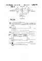
- FIG. 1is a schematic illustration of perspective view of a videotelephone set according to a first embodiment of the invention
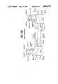
- FIG. 2is a block diagram of the videotelephone set of FIG. 1;
- FIG. 3is a block diagram of the display unit of FIG. 1;
- FIG. 4is a block diagram of the video transmitter and receiver of FIG. 1;
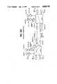
- FIG. 5is a block diagram of the scan converter of FIG. 1;
- FIG. 6is a block diagram of the scan converter of FIG. 1;
- FIG. 7is a block diagram of the freeze frame and rate conversion circuit and the sync generator of the receiver of FIG. 1;
- FIGS. 8A, 8B and 8Care views associated with the freeze frame and rate conversion circuit
- FIG. 9is a block diagram of the image enlargement circuit of FIG. 1;
- FIGS. 10A to 10Eare schematic diagrams useful for describing the mode of operation of the first embodiment of the invention.
- FIG. 11is a block diagram of a modified embodiment of the invention.
- FIG. 12is a block diagram of the still picture detector of FIG. 11;
- FIG. 13is a block diagram of a pointing arrangement
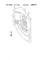
- FIGS. 14 and 15are perspective views of a videotelephone set according to a second embodiment of the invention.
- FIG. 16is a block diagram of the second embodiment
- FIG. 17is a block diagram of the dual scan conversion circuit of FIG. 16;
- FIG. 18is a block diagram of the display unit of FIG. 16;
- FIGS. 19A to 19Dare schematic diagrams useful for describing the operation of the second embodiment
- FIG. 20is a block diagram of a third embodiment of the invention.
- FIG. 21is a block diagram of a fourth embodiment of the invention.
- FIG. 22is a block diagram of the coding circuit of FIG. 21;
- FIG. 23is a block diagram of another form of the coding circuit of FIG. 21;
- FIG. 24is a flowchart describing the operation of the microprocessor of FIG. 23;
- FIG. 25is an illustration of a block of 8 ⁇ 8 cells showing a sequence in which pixels are retrieved from the cells
- FIG. 26is a block diagram of the decoding circuit of FIG. 21.
- FIG. 27is a flowchart of the microprocessor of FIG. 26.
- the videotelephone setcomprises a housing 70 having a front lower portion 71 and rear upper portion 72.
- front lower portion 71On the surface of front lower portion 71 are manually operated mode select keys including "Disable” key 73 which is used when one does not want to be seen, "Document” key 74 for sending a document, "Self View” key 75 to monitor the one's own view, "Face” key 77 for face-to-face communications, and "Enlarge” key 78.
- a (320 ⁇ 240)-pixel flat panel display 41is mounted on the rear upper portion 72 and an (80 ⁇ 60)-pixel flat panel display 31 is located above the display 41.
- a camera 11for viewing a viewer's face.
- a second video camera 21is mounted on an arm 81 which is manually pulled out of the housing 70 when in use.
- Adjacent to the camera 21is another manually operated key 76 designated “Framing".
- the "Framing" key 76is operated when the arm 81 is pulled out to allow the position of the camera 21 to be adjusted with respect to the document to put it into the field of view.
- a telephone handset 83is located on one side of the video display portion of the housing to provide audio communications.
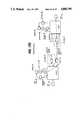
- the videotelephone setcomprises an image pickup unit 1, a display unit 2, a video transmitter 3, a video receiver 4, matrix switches 6A, 6B and a switching control logic 7 which is associated with the mode select keys 74 to 77.
- Image pickup unit 1includes the first and second video cameras 11 and 21. Each of the video cameras produces an analog television signal of a standard television format.
- a scan converter 12is connected to the output of video camera 11 to convert the high frame rate video signal into a high frame rate low resolution multiframe signal.
- the low resolution multiframe signalhas a resolution of 80 ⁇ 60 pixels from which a low frame rate low resolution multiframe signal will be derived for transmission in a manner to be described.
- a scan converter 22is connected to the output of video camera 21 to derive a high frame rate high resolution signal having 320 ⁇ 240 pixels from which a high resolution freeze frame signal will be derived for transmission. All the circuit components of image pickup unit 1 operate on timing signals including horizontal and vertical sync and blanking pulses supplied from a sync generator 13.
- the outputs of scan converter 12 and scan converter 22are applied to switch 6A and the output of sync generator 13 is applied to switch 6B.
- Each of the switches 6A and 6Bis of a conventional matrix type having crosspoints at the intersections of appropriate rows and columns, which are marked with symbols "x" where switching takes place between desired row and column lines.
- the outputs of scan converter 22 and 12are connected to the first and second rows 61, 62 of switch 6A each having three crosspoints which allow access to an input line 3a of transmitter 3 and to input lines 2a and 2b of display unit 2.
- An output line 4b of receiver 4 and an output line 3b of transmitter 3are connected to the third and fourth rows 63, 64 of switch 6A, respectively, the crosspoints on the third row 63 allowing the receiver output line 4b to access input lines 2a, 2b and 2c of display unit 2.
- the fourth row 64has only one crosspoint which establishes a connection between the transmitter output line 3b and the input line 2b of display unit 2.
- sync generator 13is supplied to the first row 65 of switch 6B having crosspoints that allow access to input lines 2d and 2e of display unit 2 and an input line 3d of transmitter 3.
- Receiver 4 and transmitter 3have output lines 4a and line 3c respectively coupled to the third and fourth rows 66 and 67 of switch 6B.
- Crosspoints on row 66allow access to display unit 2 via input lines 2d and 2e and a crosspoint on row 67 allows a connection to be established to display input line 2d.
- Converter 12includes a clock generator 123 which receives sync and control signals from the sync generator 13 to generate a 6.048-MHz clock pulse which is 384 times higher than the 15.75-kHz line frequency of the standard television signal.
- An analog-to-digital converter 111is connected to the output of camera 11 and is supplied with the 6.048-MHz clock pulse from clock generator 123 to sample the analog television signal at 6.048MHz to produce 320 digital video samples, or pixels during the effective line scan period, namely, 53-microsecond duration.
- Each pixelis converted into a 4-bit digital video signal by A/D converter 111 so that it can represent white to black with 16 levels of grey scale, the 4-bit video signal being fed on parallel lines to the input terminals of a 5-bit adder, or averaging circuit 113, of the first of a series of resolution conversion stages, one through a direct path and the other through a one-pixel delay 112.
- One-pixel delay 112comprises a set of four shift registers, for example, which are clocked with pulses from clock generator 123 to shift the 4-bit digital output from A/D converter 111 at each clock cycle and read out 4-bit digital outputs at every two clock cycles, so that the signal applied through delay 112 to adder 113 is delayed one pixel with respect to the signal directly applied to adder 119.
- the successively delayed 4-bit dataare summed by adder 113 to produce a 5-bit output and the higher 4-bits of the output are delivered at every two clock cycles, discarding the least significant bit of the sum.
- the sumis divided by two and the 4-bit output of adder 113 represents an average value of two video samples each being delayed one pixel from the other, and two successive pixel outputs from the A/D converter 111 are converted to one pixel by the adder 113 at two-pixel intervals.
- the output of adder 113is connected to the input terminals of a 5-bit adder 115, identical to adder 113, of the next stage, one through a direct path and the other through a one-pixel delay 114.
- Delay 114is clocked at one half the clock rate of the first delay conversion stage by the clock generator 123.
- two successive pixels from adder 113 and hence four successive pixels from A/D converter 111are converted to one pixel by adder 115 which is an average of the original successive four pixels.
- the resolution of the original imageis reduced by a factor 4/1 in the direction of horizontal scan.
- the 4-bit outputs of adder 115are applied to a scan converter 116 which is connected to receive control signals from the sync generator 13 and clock pulses from the clock generator 123 to generate an address signal for each pixel input from the second stage.
- the scan converter 116further includes a delay, not shown, by which the control signals from the sync generator are delayed by an amount equal to the total delay introduced by the previous stages.
- the video memory of the scan converter 116is read out at 756 kHz which is equal to one half the rate of the write mode to produce a noninterlaced "frame" at one half the frame rate of the standard interlaced television scan format.
- Four parallel bitsare supplied from the scan converter 116 to the third stage of resolution conversion which is made up of a one-line delay 118 and a 5-bit adder 119.
- One-line delay 118is formed by a set of four shift registers of 80 bits each which are driven at 756 kHz which is the same rate as the read-out rate of the scan converter 116.
- the 4-bit output of the scan converter 116 which represents a given horizontal line and the 4-bit output of the one-line delay 118 which represents a line immediately preceding the given horizontal lineare fed to the 5-bit adder 119 and pixels on the adjacent horizontal lines are summed and the higher 4 bits of the sum are delivered at a rate one half the rate of write operation to produce an average value of the pixels on adjacent lines. In this way, the resolution of the image is coarsened in the direction of vertical scan by a factor 2/1.
- the output of adder 119is then applied to the fourth stage of resolution conversion which is identically constructed to the third stage by a one-line delay 120 and a 5-bit adder 121 to reduce the resolution by a factor 2/1 in the direction of vertical scan.
- the output of adder 121is fed to a parallel-to-serial converter 122.
- the output of the converter 122has a pixel scan rate of 189 kHz and a maximum video frequency of 756 kHz (equal to the clock rate) with 30 frames per second and is applied to the switching circuit 6A.
- the scan converter 22includes an analog-to-digital converter 131, a scan converter 132, a parallel-to-serial converter 133 and a clock generator 134.
- A/D converter 131is connected to the output of camera 21 and is supplied with the 6.048-MHz clock pulse from clock generator 134 to sample the analog video signal at the clock rate to produce 320 pixels during the effective line scan period as in A/D converter 111.
- a 4-bit digital video signalis generated by A/D converter 131 for each pixel in response to each clock pulse to allow reproduction of a pixel with 16 levels of gradation, the 4-bit video signal being fed on parallel lines to the scan converter 132 which is connected to receive control signals from the sync generator 13 and clock pulses from the clock generator 134 to generate an address signal for each pixel input from the A/D converter 131.
- the scan converter 132includes a video memory with a capacity of 76,800 bits and a memory control circuit for writing the output of A/D converter 131 at odd field intervals into the video memory in response to the address signal.
- the video memory of the scan converter 132is read out at one half the rate of the write mode to produce a noninterlaced frame at one half the frame rate of the standard television scan format.
- the 4-bit parallel outputs of scan converter 132are converted to a serial 4-bit signal by the parallel-to-serial converter 133.
- Digital switching control signalsare supplied on respective parallel-bit lines 7A and 7B to switches 6A and 6B from switching control logic 7 in response to a command signal supplied from command entry keys 74-77 and an input signal from receiver 3 through an input line 4c in accordance with a switching algorithm which can be implemented with a simple logic table. Details of the switching operation will be described later.
- the display unit 2comprises the small screen display 31 having a screen resolution of 80 ⁇ 60 pixels for providing a display of a viewer seated in front of the camera 11 and the large screen display unit 41 having a screen resolution of 320 ⁇ 240 pixels for providing a display of high resolution freeze-frame pictures.
- a scan converter 32 having an (80 ⁇ 60 ⁇ 4)-bit video memoryis driven by a sync generator 33 to write a low resolution multiframe signal at a rate of 30 frames per second and read it at a rate of 60 frames per second out of the memory into the small screen display 31, so that each pixel is read twice from the scan converter 32.
- This frame rate conversionhas the effect of reducing flicker.
- a scan converter 42includes a (320 ⁇ 240 ⁇ 4)-bit video memory which is clocked by the sync generator 33 to write a high resolution freeze frame signal at 30 frames per second and read it at 60 frames per second out of the memory into the second image display unit 41.
- the input lines 2d and 2e from matrix switch 6Bare connected to the sync generator 33 to regenerate the necessary timing signals necessary for scan converters 32 and 42 and input lines 2a and 2c from switch 6A are supplied to scan converters 32 and 42, respectively.
- the input line 2b from switch 6Ais coupled to an image enlargement circuit 43 whose output is in turn connected to the scan converter 42.
- the low resolution multiframe signal from the receiver 4is coupled to the scan converter 32 via line 2a and displayed on the 80 ⁇ 60 pixel screen of the display 31.
- the inventionallows it to be displayed on the 320 ⁇ 240 pixel screen of the display 41 if desired.
- the image enlargement circuit 43is intended for this purpose and details of this circuit will be described later.
- FIG. 4shows details of the transmitter 3 and receiver 4.
- Transmitter 3comprises a frame freeze and rate conversion circuit 51 which is coupled to receive both high and low resolution signals on input line 3a from switch 6A.
- the output of the circuit 51is connected to a multiplexer 52 whose output is in turn connected to an exchange line 15.
- frame freeze and rate conversion circuit 51includes a memory which is driven by a sync generator 53 to write the high and low resolution signals.
- Sync generator 53discriminates between control signals supplied on input line 3d through switch 6B to cause the circuit 51 to perform different processing operations on the low and high resolution signal depending on signals on input line 3d.
- Receiver 4includes a demultiplexer 55 to which a second exchange line 16 is terminated to demultiplex the incoming video signal into a header and a data field, the former being supplied to a header deformatting circuit 56 which detects a freeze frame code contained in the header and supply it on output line 4c supplied on input line 4c to the switching control logic 7 and detects a sync code and feeds a sync generator 57. Further, the header deformatting circuit 56 drives a frame memory 58 if it detects a freeze frame code in the demultiplexed header to store the received freeze frame into the memory 58 and repeatedly reads it from the memory for coupling to the switch 6A through output line 4b.
- the frame freeze and rate conversion circuit 51comprises a 320 ⁇ 240 pixel read/write memory 200 of the dual port type to which the signal on input line 3a is applied and from which the stored signal is read into the multiplexer 52. Further included in the frame freeze and rate conversion circuit 51 is a pair of write address generators 201 and 202 and a pair of read address generators 203 and 204.
- the multibit address codes of the write address generators 201, 202are connected to the write address port of the memory 200, those of the read address generators 203, 204 being connected to the read address port of the memory.
- Write and read address generators 201 and 203are used to write and read the low resolution signal and write and read address generators 202 and 204 are used to write and read the high resolution signal.
- the freeze frame and rate conversion circuit 51is supplied with various control signals from the sync generator 53.
- the sync generator 53includes a write enable pulse generator 210.
- pulse generator 210In response to a count of 2,048 clock pulses (FIG. 8A) on line 3d from the sync generator 13, pulse generator 210 generates a write enable pulse with a duration of 33.3-ms which corresponds to the frame period of both low and high resolution signals. This write enable pulse is applied to the memory 200 to enable it to store the first frame of either low or high resolution signal.
- the write address counter 201is activated to supply a write address to store the first of a series of frames on an 80 ⁇ 60 pixel plane of the 320 ⁇ 240 pixel plane of the memory, and a vertical blanking signal is supplied from the sync generator 13 to a divide-by-20 counter 211. Simultaneously with the generation of the write enable pulse, the divide-by-20 counter 211 initiates counting the vertical blanking pulse and generates a pulse at the count of every 20 interlace fields of broadcast television signal format. The output of the counter 211 is successively fed to a T flip-flop 212 to generate a read enable pulse with a duration of 302.1 ms, this read enable pulse being supplied to the memory 200.
- the headeris preceded by an end-of-text (ETX) code and a pad and contains a start-of-header code (SOH), a sync code, a freeze frame code, a pointer code (which will be described later) and a start-of-text (STX) code. If the signal is a low resolution signal, the code fields of freeze frame and pointer are filled with all binary 0's.
- the write address counter 202is activated to generate a write address code to store the first of a series of the high resolution frames into the full 320 ⁇ 240 pixel plane of the memory 200, and a 64-kilobit clock pulse (which corresponds to a maximum transmission bit rate) is supplied to a divide-by-241 counter 213. Simultaneously with the generation of the write enable pulse, the divide-by-241 counter 213 initiates counting the 64-kilobit clock pulse and drives a divide-by-64 counter 214 which in turn drives a divide-by-20 counter 215 which generates a pulse at the count of every 308,480 bits of transmission.
- the output of the counter 215is successively fed to a T flip-flop 216 to cause it to generate a read enable pulse with a duration of 4,820 ms, this read enable pulse being supplied to the memory 200.
- Read address generator 204is activated to count 64-kilobit clock pulses to generate a 16-kHz read address code during the period of 4,820 ms (see FIG. 8C) to read the stored frame to produce twenty subframes of the stored frame, thus freezing the high resolution signal.
- Each of the subframeshas 15,360 bits and is multiplexed by the multiplexer 52 with a 64-bit header similar to the header shown in FIG. 8B supplied from a header formatting circuit 54.
- Header formatting circuit 54receives various timing signals from the sync generator 53 and a freeze frame code on input line 3e from the switching control logic 7 to generate a header.
- FIG. 9is an illustration of details of the image enlargement circuit 43 of FIG. 3.
- the serial input signal on input line 2bis converted to a 4-bit parallel signal by a serial-to-parallel converter 300 and fed to a sample-and-hold circuit 301 where it is first sampled in response to a first clock from a start-of-frame detector 302 via an OR gate 303 and subsequently in response to a clock supplied via the OR gate from a modulo-2 write address counter 304 which is generated at 1/4 the rate of video clock supplied on a line 33a from the sync generator 33.
- This video clockcorresponds to the bit rate of the high resolution signal and therefore the sampling rate corresponds to the bit rate of the low resolution signal.
- each pixel of the signalis sampled and held until the arrival of the next pixel.
- Four-bit video samplesare fed to a (320 ⁇ 240)-cell memory 308 of the dual port type which can read stored data simultaneously with write operation.
- the video clock on line 33a from sync generator 33is fed to the modulo-2 counter 304 to generate address codes in response to each video clock pulse to specify the lower significant column address positions A0 and A1 of the memory 308.
- a carry outputis generated by modulo-2 counter 304 and fed to a modulo-2 write address counter 305 as well as to OR gate 303.
- Modulo-2 counter 305generates address codes for every four video clock pulses to specify the lower significant row positions A9 and A10 of the memory 308.
- modulo-2 counter 305At every sixteen video clock pulses, modulo-2 counter 305 generates a carry output which is fed to a modulo-7 write address counter 306 which generates address codes for every sixteen video clock pulses to specify the column positions A2 to A8 of the memory 308. At every 320 video clock pulses, modulo-7 counter 306 supplies a carry output to a modulo-6 write address counter 307 to cause it to specify the row positions A11 to A16 of the memory 308. Counter 307 generates a carry output at the count of 240. This carry output is supplied to all the counters 304 to 307 as a reset pulse to clear their contents.
- every sixteen video samples of a low resolution signalare sequentially stored in 4 ⁇ 4 cells of the memory 308 and the original 80 ⁇ 60 pixels of the low resolution signal are stored into the 320 ⁇ 240 cells of the memory, enlarging the original image by a factor 16 to fit into the screen of display 41.
- a one-line delay 309is supplied with the output of start-of-frame detector 302 and the clock input on line 33a to pass the clock input delayed one horizontal line with respect to the start of the write operation to a read address generator 310 which is reset by the start-of-frame detector 302 to initiate a read operation in response to the higher rate video clock from sync generator 33.
- the stored datais read out of memory 308 in a sequential manner into the scan converter 42 simultaneously with the write operation.
- the simultaneous read and write operationsallow received signals to be displayed without a substantial loss of time.
- switch 6AWith the "Self View” key 75 being depressed, switch 6A is operated to establish a connection between the scan converter 12 and low resolution display 31 via scan converter 32 to monitor the field of view of the camera 21 before face-to-face communication begins between two parties A and B (see FIG. 10A).
- Switch 6Bis operated simultaneously to connect the output of sync generator 13 of image pickup unit 1 to sync generator 33 of display unit 2 over input line 2e to drive the scan converter 32 at proper timing.
- switch 6AWith the "Face” key 77 being operated, switch 6A connects the output of scan converter 12A to the input of transmitter 3A as shown in FIG. 10B.
- a low resolution multiframe signalis transmitted over a transmission line to the other party where the signal is decoded by the header deformatting circuit 64 of the receiver 4.
- Switching control logic 7receives a signal from the deformatting circuit indicating whether the received signal is a high or low resolution signal and controls the switches 6A and 6B to establish a connection between the output line 4b of receiver 4 and the input line 2a of display unit 1 to provide a display of the other party on 80 ⁇ 60 pixel display 31 and establish a connection between the output line 4a of receiver 4 and the input line 2e of display unit 2 to synchronize the display sync generator 33 with the timing of the received signal.
- the "Framing" key 76When the "Framing" key 76 is operated (see FIG. 10C), the user is allowed to adjust the field of view of the document to be sent while conducting a face-to-face communication with the other party, a process called "framing" just prior to transmission of the document.
- the output of sync generator 13 of the image pickup unit 1is connected to the transmitter input line 3d to synchronize the transmitter sync generator 53, and the output of scan converter 22 is connected to the input line 2c of display unit 2 to provide a display of the document on 320 ⁇ 240 pixel display 41.
- the switching control logic 7supplies a "freeze frame” code via the transmitter input line 3e to the header formatting circuit 54 to insert it into the header of the high resolution signal to be transmitted.
- the header deformatting circuit 64 of the receiving partydetects a "freeze frame” code and applies it to the switching control logic 7 through the receiver output line 4c to establish a connection between the receiver output line 4b and the display input line 2c.
- the data field of the received signalis fed to the frame memory 65 of the receiver to repeatedly read it out of the memory into the large screen display 41 through scan converter 42 until the next signal is arrived.
- the receiver output line 4ais connected to the display input line 2d to synchronize the display sync generator 33 with the received signal.
- the connection between the scan converter 12 and the transmitter input line 3ais reestablished to resume face-to-face communications.
- the last frame of the low resolution signalis stored in the scan converter 32 of the receiving end to provide a continuous display of the other party.
- the "Enlarge" key 78is operated during the reception of a low resolution signal.
- the receiver output line 4bis connected to the display input line 2b, as shown in FIG. 10E, and fed to the image enlargement circuit 43 where the 80 ⁇ 60 pixel plane of the signal is enlarged to fit in with the 320 ⁇ 240 pixel plane of the display 41.
- FIG. 11is an illustration of a preferred form of the switching control logic 7.
- a frame sync detector 400is provided to receive an output signal from the sync generator 13 of the image pickup unit 1 to detect a frame sync and supplies switch timing signals respectively for low and high resolution signals to the switching control logic 7 through respective lines 402 and 403.
- a frame sync detector 401receives the output of sync generator 57 of the receiver 4 to detect a frame sync and supplies switch timing signals for low and high resolution signals to the control logic 7 through lines 404, 405. These switch timing signals are used to generate the switching control signals during a period between successive frames to prevent truncation of a frame to be displayed.
- a still picture detector 406which receives the output of scan converter 22 of the image pickup unit 1 and the signal on high resolution frame timing lead 403.
- the still motion detectoris enabled in response to a signal from the "Framing" key 76 to detect when the high resolution signal contains very small amounts of moving elements indicating that a framing operation is complete and notifies this fact to the logic 7 instead of the signal from the "Document" key 74 through a manual-to-auto select switch 407. This triggers the switching control logic 7 to generate a control signal to automatically switch the operation from a document framing mode to a "document" mode.
- Detector 406includes a 1-frame delay 410 by which the high resolution signal is delayed a one-frame period and fed to a 4-bit shift register 411.
- the input signal from converter 22is also supplied to a 4-bit shift register 412.
- a subtractor 413compares the 4-bit outputs of shift registers 411 and 412 and generates a difference signal at each pixel cycle with a positive or negative sign bit and feeds an absolute value circuit 414 where the negative values of the difference are converted to positive values.
- the absolute value of differenceis integrated by an accumulator 415 over a frame interval determined by successive pulses generated by a frame counter 421 which counts pixel clock pulses from a clock generator 422.
- a total of differences between successive framescan be derived from the output of accumulator 415 and is fed to a comparator 416 for comparison with a prescribed value which represents the level of background noise which exists in motionless frames.
- Comparator 416produces a logic 1 when the total difference exceeds the noise level or a logic 0 when it falls below the noise level.
- a 64-bit shift register 417which is reset by the output of frame counter 421, is connected to the output of the comparator 416 to store successive interframe differences over the period of 64 frames.
- the output of comparator 417is fed to a decision circuit 418 which is enabled in response to a signal from an AND gate 420.
- a timing circuit 419initiates counting clock pulses in response to a signal supplied from the "Framing" key 76 and generates an enable pulse of a predetermined duration. This enable pulse is fed to the AND gate 420 to which the signal from the "Framing" key 76 is also applied.
- a simultaneous presence of the two inputs to AND gate 420, the decision circuit 418is enabled to compare the serial bit pattern of the output of comparator 417 with a bit pattern which occurs when successive frames become motionless and supplies an output to the switching control logic 7 when a match is detected between them.
- FIG. 13The pointing arrangement includes a screen touch sensor 44 of any conventional design. This sensor is laid over the screen of the display 41 to generate a signal indicating the location of a finger or any pointing device on the screen by XY coordinates. The coordinate indicating pointing signal is sent to the header formatting circuit 54 to cause it to be inserted to the header field of the transmitted high resolution freeze frame signal.
- a marker generator 45is connected to receive the pointing signal to generate a pointer mark in the form of an arrow, for example, this being fed to a mixer 46 and mixed with frame signals from the display scan converter 42 and fed to the 320 ⁇ 240 pixel display 41. Marker generator 45 further receives inputs from the header deformatting circuit 57 to produce a pointer on a received image.
- the pointercan be made to appear on a real time basis during the period of document transmission by establishing periodic time slots in the transmitted data and inserting the coordinate position signal to the time slots.
- FIG. 14A second embodiment of the present invention is illustrated in FIG. 14.
- a single camera 11' and a single display 41'are used instead of two cameras and two displays of the first embodiment.
- the 320 ⁇ 240 pixel display 41'is a flat liquid crystal display and is located on an upper rear portion 504 of the housing 500 positioned at a distance appropriate for viewing.
- a numeric key pad 502is located on a lower front portion 503 of the housing which is easily accessible by the user.
- Camera 11'is a two-dimensional CCD (charge coupled device) element and is mounted on the upper end portion of an arm 9. Arm 9 is hinged at the lower end thereof and normally rests in a slot 501 formed in the apparatus housing 500.
- CCDcharge coupled device
- the camera 11'In this rest position, the camera 11' is located adjacent the display 41' and pointed slightly upward to bring the viewer's face into the field of view.
- a switch 76'is provided instead of the "Framing" key 76. This switch is located at the lower end of the slot 501.
- the hinged arm 9When the hinged arm 9 is manually pulled forward to an upright position as shown in FIG. 15, the camera 11' is pointed downward to bring the document 80 into the field of view. When this occurs, the lower end of the arm comes into pressure contact with the switch 76', closing its circuit to generate a "framing" command signal.
- the image pickup unit 1' of the second embodimentincludes a dual scan converter 12' which combines the functions of the scan converter 12 and scan converter 22 of the first embodiment.
- Dual scan converter 12'has its output connected to the first low 61' of switch 6A' and receives a switching control signal on lead 7c from the switching control logic 7'.
- the still picture detector 406 of FIG. 12is employed instead of the "Document" key 74 of the previous embodiment.
- Still picture detector 406is connected to the output of the converter 12' through a gate 510 to detect a freeze frame and supplies an output signal to switching control logic 7' to automatically switch from document framing mode to the "document" mode.
- the dual scan converter 12'is generally similar to the scan converter 12 of FIG. 5 with the exception that it further includes switches 125 and 126.
- the switching control signal from switching control logic 7'is applied to switches 125 and 126 for selectively coupling the output of A/D converter 111 to the input of 1-pixel delay 112 and an input of adder 115 and for selectively coupling the input of parallel-to-serial converter 122 to the output of adder 121 and the output of scan converter 116.
- the low resolution (80 ⁇ 60)-pixel signalis generated when the output of A/D converter 111 is switched to the delay 112 and the input of parallel-to-serial converter 122 is switched to the output of adder 121.
- the high resolution (320 ⁇ 240)-pixel signalis generated when the output of A/D converter 111 is connected through switch 125 to the adder 115 and the input of parallel-to-serial converter 122 is connected to the output of scan converter 116.
- the display 41'is connected to the outputs of scan converters 32 and 42.
- the operational modes of the second embodimentare generally similar to those of the first embodiment.
- the output of dual scan converter 12'is connected to the display input line 2a to provide display of low resolution self image on an 80 ⁇ 60 pixel area of the 320 ⁇ 240 pixel display 41'.
- the output of converter 12'is connected to the transmitter input line 3a to transmit a low resolution signal to the other party and a received low resolution signal is coupled through the receiver output line 4b to the display input line 2a to provide display of the received 80 ⁇ 60 pixel image on the 80 ⁇ 60 pixel plane of the display 41'.
- Document framing mode(FIG.
- the switching control logic 7'responds to it by switching the output of converter 12' to the transmitter input line 3a and connecting the output of the freeze frame and rate conversion circuit 51 to the display input line 2c to display the freeze frame picture on the full 320 ⁇ 240 pixel plane of the display 41', allowing the user to monitor the transmitted version of the document, while automatically switching the system to "document" mode.
- the contacts of switch 76'are opened, terminating the document transmit mode.
- Image enlarge modecan also be performed for enlarging the 80 ⁇ 60 pixel image of a received low resolution signal of the full 320 ⁇ 240 pixel plane of the display 41' by coupling the receiver output line 4b to the display input line 2b (FIG. 19D).
- a superimpose modecan be effected by sequentially transmitting low and high resolution signals. At the receiving end the 80 ⁇ 60 pixel frame of the low resolution signal is superimposed on the 320 ⁇ 240 pixel image of the high resolution signal.
- FIG. 20is an illustration of a third embodiment of the present invention.
- data compression techniquesare employed instead of the resolution and scan conversion techniques of the previous embodiments.
- This embodimentis provided with a single video camera 600 which is synchronized with timing signals from a sync generator 601.
- the output of camera 600is coupled to coding circuits 602 and 603 and the fifth row of a matrix switch 604, the outputs of the coding circuits 602 and 603 being connected to the third and fourth rows of the switch 604.
- To the first and second rows of the switch 604are connected the outputs of decoding circuits 605 and 606, respectively.
- Signals received from the distant end of the lineare applied to and demultiplexed by a demultiplexer 612, the output of which is connected selectively to the inputs of decoding circuits 605 and 606 through a switch 607.
- a header contained in the demultiplexed signalis examined by a header deformatting circuit 613 which provides a control signal to a switching control logic 608 to notify it of the type of signal received.
- Matrix switch 604is controlled by the switching control logic 608 in response to manual commands as well as to the output of the header deformatting circuit 613.
- the first column of matrix switch 604is connected to a scan converter 614 whose output is connected to a 320 ⁇ 240 pixel display 615.
- the second column of the switch 604is connected to a multiplexer 610.
- a header formatting circuit 611is associated with the multiplexer 610 and the switching control logic 608 to insert a header into the signal to be transmitted.
- Coding circuits 602 and 603are designed to implement bit truncation coding or vector quantization coding algorithm.
- Coding circuit 603performs data compression coding on the output of the camera 600 to generate a high resolution, low frame rate video signal and coding circuit 602 performs different data compression coding and generates a low resolution, high frame rate video signal.
- Decoding circuit 605performs data expansion decoding on a received low resolution, high frame rate signal from the output of demultiplexer 612 and decoding circuit 606 performs different data expansion decoding on a received high resolution, low frame rate signal.
- Switch 607is operated in response to a signal from the logic 608 to appropriately couple the output of demultiplexer 612 to the decoding circuits 605 and 606.
- FIG. 21A modified form of the embodiment of FIG. 20 is shown in FIG. 21.
- a single coding circuit 700is provided instead of the two coding circuits 602 and 603 of FIG. 20 and a single decoding circuit 704 is used instead of the two decoding circuits of the previous embodiment.
- the output of coding circuit 700is connected to the second row of matrix switch 701 and the output of camera 600 is connected to the third row of the switch 701.
- the first column of switch 701is connected directly to the display 615 and the second column of the switch is connected to a transmitter 705.
- Decoding circuit 704is connected to the output of a receiver 706 and supplies a decoded signal to the first row of the switch 701 and a control signal to a switching control logic 703.
- Matrix switch 701connects the decoded signal to the display 615 and switches the camera output to the display 615 and the output of coding circuit 700 to the transmitter 705 in response to a switching signal from the control logic 703.
- the coding circuit 700comprises an A/D converter 711, a video memory 712 connected thereto for storing a frame of the digital form of the original camera output at prescribed intervals, typically at two to five frames per second to generate a low resolution video signal or at 0.2 to 0.5 frames per second to produce a high resolution video signal.
- a 4-bit shift register, or pixel assembly circuit 713is connected to the output of memory 712 to produce a series of consecutive four pixels.
- An averaging circuit 714is connected to the output of the pixel shift register 713 to produce a signal indicating an average value of each set of four pixels. The output of averaging circuit 714 is fed to a first input of a comparator 720.
- the second input of the comparator 720is at logic zero at this moment and hence the average value at the first input of the comparator is passed without alteration to an orthogonal encoder 721 whose output is coupled to a quantizer 722 where the orthogonal coded signal is quantized and applied to an inverse converter 725 where the average value of the original four pixels is recovered. It is noted that some error exists in the average value as a result of the data compression associated with the orthogonal coding (Hadamard coding algorithm) performed by the orthogonal encoder 721 and quantizer 722.
- the use of an orthogonal encoder having a high data compression rate and a transfer function which generates small errorsis preferred.
- the output of the inverse converter 725is applied to a pixel disassembly circuit 727 where the original four pixels are recovered and stored into the frame memory 728.
- the contents of the frame memory 728correspond to an image to be reconstructed at the receiving end of the system at each level of the hierarchical coding.
- the output of the pixel disassembly circuit 727 and the output of the memory 712are compared against each other by a comparator 717 and the difference between them is compared by a flag generator 716 with a threshold provided from a threshold generator 715.
- a logic 1, or flag "1”is generated by the flag generator 716 when the output of comparator 717 is greater than the threshold value and a logic 0, or flag "0", is generated if the threshold is not exceeded.
- the output of flag generator 716is stored in a buffer 718 and supplied to a data composer 730 where it is combined with the output of the quantizer 722 on a per block basis.
- a controller 719is connected to the output of the flag generator 716 to generate timing signals including the clock pulse necessary for addressing the memories 712, 728, and address cycle pulses synchronized with pixel processing cycles at each layer of the hierarchical coding, and layer indicating pulses for indicating the boundaries between layers.
- An address generator 723is provided to generate address data for each pixel on the storage plane of the memories 712 and 728.
- a bit allocation circuit 724is provided to allocate the most efficient coding value to each level of the video data.
- a similar coding processis performed on a newly obtained 128 ⁇ 128 pixel plane.
- the original pictureis represented by one pixel which is the average luminance of the frame.
- the information obtained at the eighth layer of the coding hierarchyis 4-bit data for transmission.
- the transmission of data on each layeris effected by the data composer 730 in a sequence opposite to the order of layers in the data composer 730 such that the most coarse data (the eighth layer) is transmitted first and the first layer last.
- the receiving end of the systemperforms inverse orthogonal transformation on a received signal the eighth layer first and the first layer last, composes pixels and writes them into frame memory. By reading the frame memory at a rate higher than the write rate, an image having a stepwisely higher resolution can be obtained.
- the hierarchical coding algorithm described abovecan be said to be a process in which plural spatial frequency filters of different levels of coarseness are assigned to the pixel plane of each frame to be transmitted and the differentials of the layered frames (eight layers in the illustrated embodiment derived from the original signal through such filters) are efficiently encoded using frame correlation technique and transmitted to the receiving end.
- the A/D converter 711is sampled at a high sampling rate for low resolution images and at a low sampling rate for high resolution images.
- the spatial frequency filterscoarse spatial frequency filters are used for low resolution images and fine spatial frequency filters for high resolution images.
- a 2-bit per pixel coding on a 64-kbps transmission linefor example, a low resolution image (128 ⁇ 128 pixels) can be obtained with a rate of two frames per second and a high resolution image (256 ⁇ 256 pixels) can be obtained with a rate of 0.5 frames per second.
- the switching of the spatial frequency filterscan be achieved by discarding lower layers. If the eight layers are divided into three time intervals such that the eighth to fourth layers belong to the first time interval, the third and second layers belong to the second time interval and the first layer belong to the third time interval, a low resolution image is obtained by terminating the transmission at the end of the second time interval and proceeding with the transmission of the next frame.
- image datais transmitted for an interval of 0.5 second in the case of 2 frames per second transmission before proceeding with the transmission of the next frame. Since the amount of information to be transmitted varies significantly depending on the textures of the image, the hierarchical coding technique allows highly efficient transmission of signals and eliminates layer control and permits the encoder to be used for processing both high and low resolution signals.
- the switching between high and low resolution transmissionscan be effected by the application of a logic 1 or logic 0 through an input terminal 733 to the A/D converter 711 in response to a manual command entered through a switch on the apparatus housing.
- the A/D converter 711In response to a logic 0 input from the terminal 733, the A/D converter 711 generates a 4-bit output which represents one of 16 gradations and in response to a logic 1 input the converter generates a logic 0 output for 0 to 8 levels of gradation and a logic 1 output for 9 to 16 levels of gradation.
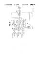
- FIG. 23An alternative embodiment of the coding circuit 700 is illustrated in FIG. 23.
- the input to the coder 700is RGB color signals which are respectively fed to A/D converters 800R, 800G, 800B and converted to parallel form by serial-to-parallel converters 801R, 801G, 801B and fed to dual port memories 802-1, 802-2 and 802-3 each having 640 ⁇ 480 pixels.
- These memoriesare addressed by a write address generator 803 which counts sync timing pulses from sync generator 601 and generates a write address for every nine frames in a manner similar to that provided by the freeze frame and rate conversion circuit 51 of FIG. 4 as it treats the low resolution signal (see FIG. 8A).
- a read address codeis supplied to the memories 802 from a microprocessor 804, or video signal processor, through an address bus 805.
- Memories 802are connected through a data bus 806 to the microprocessor 804.
- Microprocessor 804has an output connected to the second row of switch 701.
- Write address generator 803is supplied with a proceed-to-write control signal from the switching control logic 703 and microprocessor 804 is supplied with a high/low resolution command signal from the control logic 703.
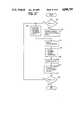
- FIG. 24is a flowchart describing the operation of the microprocessor 804.
- the programstarts with operations block 810 in which the RGB signals of the NTSC color television format are converted to the luminance Y, color difference signals R-Y and B-Y by performing known matrix operations on pixels stored in corresponding cells of the memories 802-1, 802-2, 802-3.
- the processed pixelsare stored back into the memories 802 overwriting the original pixel data so that the Y, R-Y and B-Y pixel data are stored into memories 802-1, 802-2 and 802-3, respectively.
- controlexits to operations block 811 which directs the sequential reading of the color difference data R-Y and B-Y from memories 802-2 and 802-3 and directs the 2-to-1 subsampling of pixels, i.e, sampling one pixel for every two retrieved pixels in both the horizontal and vertical directions, thereby reducing the number of pixels by 1/4 the original quantity.
- This data compressionis to take advantage of the fact that the human eyes are less sensitive to colors than they are to luminance. With the chrominance components being reduced to 1/4 the original quantity, a total of the luminance and chrominance components gives a data compression ratio which is one half the original total quantity.
- the subtracting sampling processis bypassed.
- operations block 812which directs the reading of data from 8 ⁇ 8 cells (which form a block) from each memory 802 and performs discrete cosine transform (DCT) on the retrieved 64 pixels which are then stored back into the original cell positions.
- DCTdiscrete cosine transform
- This DCT conversiondetermines the resolution and hence the spatial frequency filter of the encoder 700.
- the upper left corner of each blockis filled with a pixel representing an average DC level of all the pixels of the block. Pixels in the rows and columns of each block represent the AC components of the signal and are arranged in an ascending order of resolution in a direction from left to right and in a direction from top to bottom.
- This coding processinvolves a run length coding of the logic 1's and 0's of the quantized values and an entropy coding of the DCT coefficients.
- the modified Huffman codingis performed in block 815 on all pixels retrieved from cells #0 to #63 and control exits to the end of the program.
- exitis to operations block 816 which directs the retrieving of pixels from cells #0 to #5 and the performing of the modified Huffman coding on such pixels, and control then returns to block 810 to repeat the process on the next frame.
- a data compression ratio of 1/6 to 1/32can be achieved without introducing noticeable degradation of picture quality.
- a data compression of down to 0.1 to 0.75 bits per pixelcan be achieved if allowance is made for the degradation of image gradation as well as resolution.
- the following relationswere obtained between entropy (bits/pixel) and frame transmission time (seconds/frame) of a color video over a 64-kbps ISDN exchange line.
- Decoder 704involves a process inverse to that of the encoder 700.
- decoder 704includes a microprocessor 821 connected to the output of receiver 706 to perform a decoding process on the received signal in a manner as shown in FIG. 27.
- Dual port memories 822-1 to 822-3are connected to the output of microprocessor 821 to cooperate with it to write received data into the memories to perform the decoding process. recovering the R, G, B primary color signals.
- a read address generator 823which is connected to the memories 822, responds to a control signal supplied from the microprocessor 821 to read the recovered data into parallel-to-serial converters 824R, 824G, 824B whose outputs are respectively coupled to D/A converters 825R, 825G and 825B.
- operations block 832performs a modified Huffman decoding on pixels in cells #0 to #5 of each block.
- Operations blocks 831 and 832are followed by a sequence of operations blocks 833, 834, 835 and 836.
- scaler dequantizationis performed in a manner inverse to the scaler quantization performed by operations block 813 of FIG. 24.
- DCT reconversion processinverse to that of the process of block 824 is performed by operations block 834.
- Operations block 835performs interpolation between successive pixels derived by the DCT decoding process to recover the luminance Y and color difference signals R-Y, B-Y.
Landscapes
- Engineering & Computer Science (AREA)
- Multimedia (AREA)
- Signal Processing (AREA)
- Television Systems (AREA)
Abstract
Description
______________________________________ Entropy Transmission Time ______________________________________ 24 115 4 19.2 0.75 3.6 0.2 0.96 0.1 0.48 ______________________________________
Claims (41)
Applications Claiming Priority (4)
| Application Number | Priority Date | Filing Date | Title |
|---|---|---|---|
| JP16352287AJPS647881A (en) | 1987-06-30 | 1987-06-30 | Composition picture terminal equipment |
| JP62-163522 | 1987-06-30 | ||
| JP62-113666[U] | 1987-07-24 | ||
| JP11366687UJPS6418882U (en) | 1987-07-24 | 1987-07-24 |
Publications (1)
| Publication Number | Publication Date |
|---|---|
| US4888795Atrue US4888795A (en) | 1989-12-19 |
Family
ID=26452610
Family Applications (1)
| Application Number | Title | Priority Date | Filing Date |
|---|---|---|---|
| US07/212,498Expired - LifetimeUS4888795A (en) | 1987-06-30 | 1988-06-28 | Videotelephone apparatus for transmitting high and low resolution video signals over telephone exchange lines |
Country Status (1)
| Country | Link |
|---|---|
| US (1) | US4888795A (en) |
Cited By (115)
| Publication number | Priority date | Publication date | Assignee | Title |
|---|---|---|---|---|
| US5012348A (en)* | 1989-02-27 | 1991-04-30 | Telenorma Gmbh | Terminal device for picture communication |
| US5046079A (en)* | 1988-10-14 | 1991-09-03 | Hashimoto Corporation | Telephone answering device with TV telephone |
| US5063440A (en)* | 1989-07-31 | 1991-11-05 | Goldstar Co., Ltd. | Still/moving picture selection control circuit for video phone system |
| US5142380A (en)* | 1989-10-23 | 1992-08-25 | Ricoh Company, Ltd. | Image data processing apparatus |
| US5218627A (en)* | 1990-12-19 | 1993-06-08 | U S West Advanced Technologies | Decentralized video telecommunication system |
| US5253286A (en)* | 1991-03-08 | 1993-10-12 | Fujitsu Limited | Apparatus for focusing image in television camera for video telephone |
| EP0524623A3 (en)* | 1991-07-24 | 1993-10-27 | Hitachi Ltd | Video telephone |
| US5325194A (en)* | 1991-08-29 | 1994-06-28 | Fujitsu Limited | Multipoint video conferencing system |
| US5353063A (en)* | 1990-04-04 | 1994-10-04 | Canon Kabushiki Kaisha | Method and apparatus for processing and/or displaying image data based on control data received with the image data |
| US5357281A (en)* | 1991-11-07 | 1994-10-18 | Canon Kabushiki Kaisha | Image processing apparatus and terminal apparatus |
| US5375068A (en)* | 1992-06-03 | 1994-12-20 | Digital Equipment Corporation | Video teleconferencing for networked workstations |
| US5396269A (en)* | 1991-02-20 | 1995-03-07 | Hitachi, Ltd. | Television telephone |
| US5434913A (en)* | 1993-11-24 | 1995-07-18 | Intel Corporation | Audio subsystem for computer-based conferencing system |
| US5475421A (en)* | 1992-06-03 | 1995-12-12 | Digital Equipment Corporation | Video data scaling for video teleconferencing workstations communicating by digital data network |
| US5489938A (en)* | 1991-05-13 | 1996-02-06 | Ricoh Company, Ltd. | Television conference apparatus including a material picturing device |
| US5493568A (en)* | 1993-11-24 | 1996-02-20 | Intel Corporation | Media dependent module interface for computer-based conferencing system |
| US5499241A (en)* | 1993-09-17 | 1996-03-12 | Scientific-Atlanta, Inc. | Broadband communications system |
| US5506954A (en)* | 1993-11-24 | 1996-04-09 | Intel Corporation | PC-based conferencing system |
| US5508713A (en)* | 1992-06-19 | 1996-04-16 | Ricoh Company, Ltd. | Control system for picture display apparatus having improved displaying data transmission system |
| FR2725805A1 (en)* | 1994-10-18 | 1996-04-19 | Alcatel Business Systems | APPARATUS, SCREEN AND CAMERA HAVING OBJECTIVE ORIENTATION MECHANISM |
| WO1996014711A1 (en)* | 1994-11-03 | 1996-05-17 | Picturetel Corporation | Method and apparatus for visual communications in a scalable network environment |
| US5566238A (en)* | 1993-11-24 | 1996-10-15 | Intel Corporation | Distributed processing of audio signals |
| US5574934A (en)* | 1993-11-24 | 1996-11-12 | Intel Corporation | Preemptive priority-based transmission of signals using virtual channels |
| US5579389A (en)* | 1993-11-24 | 1996-11-26 | Intel Corporation | Histogram-based processing of audio signals |
| US5581555A (en)* | 1993-09-17 | 1996-12-03 | Scientific-Atlanta, Inc. | Reverse path allocation and contention resolution scheme for a broadband communications system |
| US5587735A (en)* | 1991-07-24 | 1996-12-24 | Hitachi, Ltd. | Video telephone |
| US5592547A (en)* | 1993-11-24 | 1997-01-07 | Intel Corporation | Processing audio signals using a discrete state machine |
| US5594859A (en)* | 1992-06-03 | 1997-01-14 | Digital Equipment Corporation | Graphical user interface for video teleconferencing |
| US5594726A (en)* | 1993-09-17 | 1997-01-14 | Scientific-Atlanta, Inc. | Frequency agile broadband communications system |
| US5600797A (en)* | 1993-11-24 | 1997-02-04 | Intel Corporation | System for identifying new client and allocating bandwidth thereto by monitoring transmission of message received periodically from client computers informing of their current status |
| US5610975A (en)* | 1988-08-26 | 1997-03-11 | Canon Kabushiki Kaisha | Visual telephone apparatus |
| US5623690A (en)* | 1992-06-03 | 1997-04-22 | Digital Equipment Corporation | Audio/video storage and retrieval for multimedia workstations by interleaving audio and video data in data file |
| US5631967A (en)* | 1993-11-24 | 1997-05-20 | Intel Corporation | Processing audio signals using a state variable |
| US5673393A (en)* | 1993-11-24 | 1997-09-30 | Intel Corporation | Managing bandwidth over a computer network having a management computer that allocates bandwidth to client computers upon request |
| US5701581A (en)* | 1993-12-28 | 1997-12-23 | Hitachi Denshi Kabushiki Kaisha | Method for bidirectionally transmitting digital video signal and digital video signal bidirectional transmission system |
| US5740283A (en)* | 1995-07-06 | 1998-04-14 | Rubin, Bednarek & Associates, Inc. | Digital video compression utilizing mixed vector and scalar outputs |
| US5748770A (en)* | 1993-11-30 | 1998-05-05 | Polaroid Corporation | System and method for color recovery using discrete cosine transforms |
| US5754765A (en)* | 1993-11-24 | 1998-05-19 | Intel Corporation | Automatic transport detection by attempting to establish communication session using list of possible transports and corresponding media dependent modules |
| US5777663A (en)* | 1991-02-20 | 1998-07-07 | Hitachi, Ltd. | Picture codec and teleconference terminal equipment |
| US5809237A (en)* | 1993-11-24 | 1998-09-15 | Intel Corporation | Registration of computer-based conferencing system |
| US5821995A (en)* | 1994-12-23 | 1998-10-13 | Hitachi Denshi Kabushiki Kaisha | Method and apparatus for controlling transmission of multiplexed video signals |
| US5862388A (en)* | 1993-11-24 | 1999-01-19 | Intel Corporation | Interrupt-time processing of received signals |
| US5936945A (en)* | 1991-07-15 | 1999-08-10 | Hitachi, Ltd. | Teleconference module with video codec for motion picture data |
| US5949891A (en)* | 1993-11-24 | 1999-09-07 | Intel Corporation | Filtering audio signals from a combined microphone/speaker earpiece |
| US5956430A (en)* | 1996-02-19 | 1999-09-21 | Fuji Xerox Co., Ltd. | Image information coding apparatus and method using code amount of a selected pixel block for changing coding parameter |
| WO1999048294A1 (en)* | 1998-03-16 | 1999-09-23 | Wincor Nixdorf Gmbh & Co. Kg | Multimedia communication terminal |
| US5999644A (en)* | 1989-10-31 | 1999-12-07 | Canon Kabushiki Kaisha | Image processing apparatus and method |
| US6009305A (en)* | 1993-12-28 | 1999-12-28 | Hitachi Denshi Kabushiki Kaisha | Digital video signal multiplex transmission system |
| USD419996S (en)* | 1998-08-12 | 2000-02-01 | Evans Consoles Inc. | Telephone |
| WO2000007362A1 (en)* | 1998-07-31 | 2000-02-10 | Intel Corporation | Method and apparatus for reducing flicker in a video image sequence |
| US6037991A (en)* | 1996-11-26 | 2000-03-14 | Motorola, Inc. | Method and apparatus for communicating video information in a communication system |
| US6125398A (en)* | 1993-11-24 | 2000-09-26 | Intel Corporation | Communications subsystem for computer-based conferencing system using both ISDN B channels for transmission |
| US6181784B1 (en) | 1991-05-21 | 2001-01-30 | Vtel Corporation | Computer controlled video multiplexer for video conferencing and message systems |
| US6212547B1 (en) | 1993-10-01 | 2001-04-03 | Collaboration Properties, Inc. | UTP based video and data conferencing |
| US20010009439A1 (en)* | 2000-01-21 | 2001-07-26 | Hwang Jeong Hwan | Personal computer camera with various applications |
| US6345390B1 (en) | 1993-12-28 | 2002-02-05 | Hitachi Denshi Kabushiki Kaisha | Bidirectional digital signal transmission system and repeater for the same |
| US20020030695A1 (en)* | 1999-10-21 | 2002-03-14 | Yoshihisa Narui | Single horizontal scan range CRT monitor |
| US6380967B1 (en)* | 1996-12-07 | 2002-04-30 | Frank Sacca | System to capture, store, and retrieve composite video for transmission over telephone lines |
| US20020124051A1 (en)* | 1993-10-01 | 2002-09-05 | Ludwig Lester F. | Marking and searching capabilities in multimedia documents within multimedia collaboration networks |
| US6577324B1 (en) | 1992-06-03 | 2003-06-10 | Compaq Information Technologies Group, L.P. | Video and audio multimedia pop-up documentation by performing selected functions on selected topics |
| US20030151671A1 (en)* | 2001-04-27 | 2003-08-14 | Kosuke Kubota | Camera device and electronic device having the camera device |
| US6738357B1 (en) | 1993-06-09 | 2004-05-18 | Btg International Inc. | Method and apparatus for multiple media digital communication system |
| US20040126031A1 (en)* | 2002-12-30 | 2004-07-01 | Dwyer Michael K. | Run length encoded digital image |
| US20040141067A1 (en)* | 2002-11-29 | 2004-07-22 | Fujitsu Limited | Picture inputting apparatus |
| US6803948B1 (en)* | 1998-07-02 | 2004-10-12 | Koninklijke Philips Electronics N.V. | Television camera with off-line parameter adjustment |
| US20050047634A1 (en)* | 2003-05-12 | 2005-03-03 | Wilfried Schmidt | Method and apparatus for monitoring electronic transmission of an image |
| US6898620B1 (en) | 1996-06-07 | 2005-05-24 | Collaboration Properties, Inc. | Multiplexing video and control signals onto UTP |
| US20050149649A1 (en)* | 1998-07-21 | 2005-07-07 | Carneal Bruce L. | Method and apparatus for multiple access in a communication system |
| US20050195203A1 (en)* | 2004-03-02 | 2005-09-08 | Ittiam Systems (P) Ltd. | Method and apparatus for high rate concurrent read-write applications |
| US6970537B2 (en) | 1989-07-14 | 2005-11-29 | Inline Connection Corporation | Video transmission and control system utilizing internal telephone lines |
| US20050270304A1 (en)* | 2004-06-02 | 2005-12-08 | Atsushi Obinata | Display controller, electronic apparatus and method for supplying image data |
| US7145990B2 (en) | 1999-06-11 | 2006-12-05 | Inline Connection Corporation | High-speed data communication over a residential telephone wiring network |
| US7185054B1 (en) | 1993-10-01 | 2007-02-27 | Collaboration Properties, Inc. | Participant display and selection in video conference calls |
| US7274688B2 (en) | 2000-04-18 | 2007-09-25 | Serconet Ltd. | Telephone communication system over a single telephone line |
| US7317793B2 (en) | 2003-01-30 | 2008-01-08 | Serconet Ltd | Method and system for providing DC power on local telephone lines |
| US20080045188A1 (en)* | 2000-08-01 | 2008-02-21 | Lg Electronics Inc. | Image signal transmitting/receiving apparatus and method |
| US7436842B2 (en) | 2001-10-11 | 2008-10-14 | Serconet Ltd. | Outlet with analog signal adapter, a method for use thereof and a network using said outlet |
| US7483524B2 (en) | 1999-07-20 | 2009-01-27 | Serconet, Ltd | Network for telephony and data communication |
| US7522714B2 (en) | 2000-03-20 | 2009-04-21 | Serconet Ltd. | Telephone outlet for implementing a local area network over telephone lines and a local area network using such outlets |
| USRE40704E1 (en) | 1995-02-24 | 2009-04-28 | Apple Inc. | System for terminating multicast channel and data broadcast when at least two second endpoints do not transmit positive acknowledgement message to first endpoint |
| US7542554B2 (en) | 2001-07-05 | 2009-06-02 | Serconet, Ltd | Telephone outlet with packet telephony adapter, and a network using same |
| US7577240B2 (en) | 1989-07-14 | 2009-08-18 | Inline Connection Corporation | Two-way communication over a single transmission line between one or more information sources and a group of telephones, computers, and televisions |
| US7587001B2 (en) | 2006-01-11 | 2009-09-08 | Serconet Ltd. | Apparatus and method for frequency shifting of a wireless signal and systems using frequency shifting |
| US7633966B2 (en) | 2000-04-19 | 2009-12-15 | Mosaid Technologies Incorporated | Network combining wired and non-wired segments |
| US7686653B2 (en) | 2003-09-07 | 2010-03-30 | Mosaid Technologies Incorporated | Modular outlet |
| US7835509B2 (en) | 1993-03-12 | 2010-11-16 | Telebuyer, Llc | Commercial product routing system with video vending capability |
| US7835508B1 (en)* | 1993-03-12 | 2010-11-16 | Telebuyer, Llc | Commercial product routing system with video vending capability |
| US7873058B2 (en) | 2004-11-08 | 2011-01-18 | Mosaid Technologies Incorporated | Outlet with analog signal adapter, a method for use thereof and a network using said outlet |
| US20110157030A1 (en)* | 2009-12-31 | 2011-06-30 | Amlogic Co., Ltd. | Methods and Systems for Data Serialization |
| US20110181686A1 (en)* | 2003-03-03 | 2011-07-28 | Apple Inc. | Flow control |
| US8175649B2 (en) | 2008-06-20 | 2012-05-08 | Corning Mobileaccess Ltd | Method and system for real time control of an active antenna over a distributed antenna system |
| US8238328B2 (en) | 2003-03-13 | 2012-08-07 | Mosaid Technologies Incorporated | Telephone system having multiple distinct sources and accessories therefor |
| US8270430B2 (en) | 1998-07-28 | 2012-09-18 | Mosaid Technologies Incorporated | Local area network of serial intelligent cells |
| US8325759B2 (en) | 2004-05-06 | 2012-12-04 | Corning Mobileaccess Ltd | System and method for carrying a wireless based signal over wiring |
| US20130027346A1 (en)* | 2011-07-27 | 2013-01-31 | Andriy Yarosh | Method and apparatus for parallel scanning and data processing for touch sense arrays |
| US20130215322A1 (en)* | 2012-02-20 | 2013-08-22 | Ken-A-Vision Manufacturing Company, Inc. | Document camera with automatically switched operating parameters |
| US20130251221A1 (en)* | 2010-12-14 | 2013-09-26 | Koninklijke Philips Electronics N.V. | Ultrasound imaging system and method with peak intensity detection |
| US8594133B2 (en) | 2007-10-22 | 2013-11-26 | Corning Mobileaccess Ltd. | Communication system using low bandwidth wires |
| US20140313336A1 (en)* | 2013-04-22 | 2014-10-23 | Utc Fire & Security Corporation | Efficient data transmission |
| US8897215B2 (en) | 2009-02-08 | 2014-11-25 | Corning Optical Communications Wireless Ltd | Communication system using cables carrying ethernet signals |
| US9167200B2 (en) | 2011-01-14 | 2015-10-20 | Ricoh Company, Ltd. | Communication apparatus |
| US9184960B1 (en) | 2014-09-25 | 2015-11-10 | Corning Optical Communications Wireless Ltd | Frequency shifting a communications signal(s) in a multi-frequency distributed antenna system (DAS) to avoid or reduce frequency interference |
| US9338823B2 (en) | 2012-03-23 | 2016-05-10 | Corning Optical Communications Wireless Ltd | Radio-frequency integrated circuit (RFIC) chip(s) for providing distributed antenna system functionalities, and related components, systems, and methods |
| US9596388B2 (en) | 2008-07-07 | 2017-03-14 | Gopro, Inc. | Camera housing with integrated expansion module |
| US10623665B2 (en)* | 2014-03-04 | 2020-04-14 | Black Diamond Video, Inc. | Converter device and system including converter device |
| USD894256S1 (en) | 2018-08-31 | 2020-08-25 | Gopro, Inc. | Camera mount |
| USD905786S1 (en) | 2018-08-31 | 2020-12-22 | Gopro, Inc. | Camera mount |
| US10928711B2 (en) | 2018-08-07 | 2021-02-23 | Gopro, Inc. | Camera and camera mount |
| US10986165B2 (en) | 2004-01-13 | 2021-04-20 | May Patents Ltd. | Information device |
| USD991318S1 (en) | 2020-08-14 | 2023-07-04 | Gopro, Inc. | Camera |
| USD997232S1 (en) | 2019-09-17 | 2023-08-29 | Gopro, Inc. | Camera |
| USD1036536S1 (en) | 2017-12-28 | 2024-07-23 | Gopro, Inc. | Camera |
| US12321084B2 (en) | 2022-08-12 | 2025-06-03 | Gopro, Inc. | Interconnect mechanism for image capture device |
| US12379650B2 (en) | 2023-02-15 | 2025-08-05 | Gopro, Inc. | Reinforced image capture devices including interconnect mechanisms with a threaded accessory interface |
| USD1096914S1 (en) | 2024-03-15 | 2025-10-07 | Gopro, Inc. | Camera mount |
Citations (2)
| Publication number | Priority date | Publication date | Assignee | Title |
|---|---|---|---|---|
| US3781477A (en)* | 1968-10-08 | 1973-12-25 | Ericsson Telefon Ab L M | Picture telephone system at which the video signal is adapted to the character of the picture |
| US4258387A (en)* | 1979-10-17 | 1981-03-24 | Lemelson Jerome H | Video telephone |
- 1988
- 1988-06-28USUS07/212,498patent/US4888795A/ennot_activeExpired - Lifetime
Patent Citations (2)
| Publication number | Priority date | Publication date | Assignee | Title |
|---|---|---|---|---|
| US3781477A (en)* | 1968-10-08 | 1973-12-25 | Ericsson Telefon Ab L M | Picture telephone system at which the video signal is adapted to the character of the picture |
| US4258387A (en)* | 1979-10-17 | 1981-03-24 | Lemelson Jerome H | Video telephone |
Non-Patent Citations (4)
| Title |
|---|
| Peter Klein, "Desktop Teleconferencing", Siemens Telcom Report, Jan./Feb. 1987. |
| Peter Klein, Desktop Teleconferencing , Siemens Telcom Report, Jan./Feb. 1987.* |
| Stephen Weinstein, "Telecommunications in the Coming Decades", IEEE Spectrum, Nov. 1987. |
| Stephen Weinstein, Telecommunications in the Coming Decades , IEEE Spectrum, Nov. 1987.* |
Cited By (260)
| Publication number | Priority date | Publication date | Assignee | Title |
|---|---|---|---|---|
| US5850251A (en)* | 1988-08-26 | 1998-12-15 | Canon Kabushiki Kaisha | Visual telephone apparatus |
| US5610975A (en)* | 1988-08-26 | 1997-03-11 | Canon Kabushiki Kaisha | Visual telephone apparatus |
| US5046079A (en)* | 1988-10-14 | 1991-09-03 | Hashimoto Corporation | Telephone answering device with TV telephone |
| US5012348A (en)* | 1989-02-27 | 1991-04-30 | Telenorma Gmbh | Terminal device for picture communication |
| US7227932B2 (en) | 1989-07-14 | 2007-06-05 | Inline Connection Corporation | Multi-band data over voice communication system and method |
| US7149289B2 (en) | 1989-07-14 | 2006-12-12 | Inline Connection Corporation | Interactive data over voice communication system and method |
| US7224780B2 (en) | 1989-07-14 | 2007-05-29 | Inline Connection Corporation | Multichannel transceiver using redundant encoding and strategic channel spacing |
| US7577240B2 (en) | 1989-07-14 | 2009-08-18 | Inline Connection Corporation | Two-way communication over a single transmission line between one or more information sources and a group of telephones, computers, and televisions |
| US6970537B2 (en) | 1989-07-14 | 2005-11-29 | Inline Connection Corporation | Video transmission and control system utilizing internal telephone lines |
| US5063440A (en)* | 1989-07-31 | 1991-11-05 | Goldstar Co., Ltd. | Still/moving picture selection control circuit for video phone system |
| US5142380A (en)* | 1989-10-23 | 1992-08-25 | Ricoh Company, Ltd. | Image data processing apparatus |
| US5999644A (en)* | 1989-10-31 | 1999-12-07 | Canon Kabushiki Kaisha | Image processing apparatus and method |
| US5353063A (en)* | 1990-04-04 | 1994-10-04 | Canon Kabushiki Kaisha | Method and apparatus for processing and/or displaying image data based on control data received with the image data |
| US5218627A (en)* | 1990-12-19 | 1993-06-08 | U S West Advanced Technologies | Decentralized video telecommunication system |
| US5966164A (en)* | 1991-02-10 | 1999-10-12 | Hitachi, Ltd. | Television telephone |
| US5396269A (en)* | 1991-02-20 | 1995-03-07 | Hitachi, Ltd. | Television telephone |
| EP0836323A1 (en)* | 1991-02-20 | 1998-04-15 | Hitachi, Ltd. | Television telephone |
| US5677727A (en)* | 1991-02-20 | 1997-10-14 | Hitachi, Ltd. | Television telephone |
| US6034715A (en)* | 1991-02-20 | 2000-03-07 | Hitachi, Ltd. | Video telephone for the real-time exchange of image and other data through a digital communications network |
| US5777663A (en)* | 1991-02-20 | 1998-07-07 | Hitachi, Ltd. | Picture codec and teleconference terminal equipment |
| US5253286A (en)* | 1991-03-08 | 1993-10-12 | Fujitsu Limited | Apparatus for focusing image in television camera for video telephone |
| US5489938A (en)* | 1991-05-13 | 1996-02-06 | Ricoh Company, Ltd. | Television conference apparatus including a material picturing device |
| US6181784B1 (en) | 1991-05-21 | 2001-01-30 | Vtel Corporation | Computer controlled video multiplexer for video conferencing and message systems |
| US5936945A (en)* | 1991-07-15 | 1999-08-10 | Hitachi, Ltd. | Teleconference module with video codec for motion picture data |
| US6285391B1 (en) | 1991-07-15 | 2001-09-04 | Hitachi, Ltd. | Picture codec and teleconference terminal equipment |
| US5587735A (en)* | 1991-07-24 | 1996-12-24 | Hitachi, Ltd. | Video telephone |
| EP0524623A3 (en)* | 1991-07-24 | 1993-10-27 | Hitachi Ltd | Video telephone |
| US5400068A (en)* | 1991-07-24 | 1995-03-21 | Hitachi, Ltd. | Video telephone |
| US5325194A (en)* | 1991-08-29 | 1994-06-28 | Fujitsu Limited | Multipoint video conferencing system |
| US5357281A (en)* | 1991-11-07 | 1994-10-18 | Canon Kabushiki Kaisha | Image processing apparatus and terminal apparatus |
| US6195683B1 (en) | 1992-06-03 | 2001-02-27 | Compaq Computer Corporation | Video teleconferencing for networked workstations |
| US5623690A (en)* | 1992-06-03 | 1997-04-22 | Digital Equipment Corporation | Audio/video storage and retrieval for multimedia workstations by interleaving audio and video data in data file |
| US6577324B1 (en) | 1992-06-03 | 2003-06-10 | Compaq Information Technologies Group, L.P. | Video and audio multimedia pop-up documentation by performing selected functions on selected topics |
| US5594859A (en)* | 1992-06-03 | 1997-01-14 | Digital Equipment Corporation | Graphical user interface for video teleconferencing |
| US5546324A (en)* | 1992-06-03 | 1996-08-13 | Digital Equipment Corporation | Video teleconferencing for networked workstations |
| US5594495A (en)* | 1992-06-03 | 1997-01-14 | Digital Equipment Corporation | Video data scaling for video teleconferencing workstations communicating by digital data network |
| US6320588B1 (en) | 1992-06-03 | 2001-11-20 | Compaq Computer Corporation | Audio/video storage and retrieval for multimedia workstations |
| US5608653A (en)* | 1992-06-03 | 1997-03-04 | Digital Equipment Corporation | Video teleconferencing for networked workstations |
| US5375068A (en)* | 1992-06-03 | 1994-12-20 | Digital Equipment Corporation | Video teleconferencing for networked workstations |
| US5831666A (en)* | 1992-06-03 | 1998-11-03 | Digital Equipment Corporation | Video data scaling for video teleconferencing workstations communicating by digital data network |
| US5475421A (en)* | 1992-06-03 | 1995-12-12 | Digital Equipment Corporation | Video data scaling for video teleconferencing workstations communicating by digital data network |
| US5508713A (en)* | 1992-06-19 | 1996-04-16 | Ricoh Company, Ltd. | Control system for picture display apparatus having improved displaying data transmission system |
| US7835508B1 (en)* | 1993-03-12 | 2010-11-16 | Telebuyer, Llc | Commercial product routing system with video vending capability |
| US9053485B2 (en) | 1993-03-12 | 2015-06-09 | Telebuyer, Llc | Security monitoring system with image comparison of monitored location |
| US8842151B2 (en) | 1993-03-12 | 2014-09-23 | Telebuyer, Llc | Security monitoring system with flexible monitoring sequence |
| US8207998B1 (en)* | 1993-03-12 | 2012-06-26 | Telebuyer, Llc | Commercial product routing system with video vending capability |
| US8836749B2 (en) | 1993-03-12 | 2014-09-16 | Telebuyer, Llc | Security monitoring system with combined video and graphics display |
| US7835509B2 (en) | 1993-03-12 | 2010-11-16 | Telebuyer, Llc | Commercial product routing system with video vending capability |
| US6738357B1 (en) | 1993-06-09 | 2004-05-18 | Btg International Inc. | Method and apparatus for multiple media digital communication system |
| US7050425B2 (en) | 1993-06-09 | 2006-05-23 | Btg International Inc. | Apparatus for multiple media digital communication |
| US7075924B2 (en) | 1993-06-09 | 2006-07-11 | Btg International Inc. | Methods for multiple media digital communication |
| US8116301B2 (en) | 1993-06-09 | 2012-02-14 | Rpx Corporation | Method and apparatus for multiple media digital communication system |
| US20040218628A1 (en)* | 1993-06-09 | 2004-11-04 | Andreas Richter | Method and apparatus for multiple media digital communication system |
| US20040228351A1 (en)* | 1993-06-09 | 2004-11-18 | Andreas Richter | Method and apparatus for multiple media digital communication system |
| US5719872A (en)* | 1993-09-17 | 1998-02-17 | Scientific-Atlanta, Inc. | Reverse path allocation and contention resolution scheme for a broadband communications system |
| US5499241A (en)* | 1993-09-17 | 1996-03-12 | Scientific-Atlanta, Inc. | Broadband communications system |
| US5594726A (en)* | 1993-09-17 | 1997-01-14 | Scientific-Atlanta, Inc. | Frequency agile broadband communications system |
| US5581555A (en)* | 1993-09-17 | 1996-12-03 | Scientific-Atlanta, Inc. | Reverse path allocation and contention resolution scheme for a broadband communications system |
| US6343314B1 (en) | 1993-10-01 | 2002-01-29 | Collaboration Properties, Inc. | Remote participant hold and disconnect during videoconferencing |
| US6789105B2 (en) | 1993-10-01 | 2004-09-07 | Collaboration Properties, Inc. | Multiple-editor authoring of multimedia documents including real-time video and time-insensitive media |
| US6959322B2 (en) | 1993-10-01 | 2005-10-25 | Collaboration Properties, Inc. | UTP based video conferencing |
| US7152093B2 (en) | 1993-10-01 | 2006-12-19 | Collaboration Properties, Inc. | System for real-time communication between plural users |
| US7185054B1 (en) | 1993-10-01 | 2007-02-27 | Collaboration Properties, Inc. | Participant display and selection in video conference calls |
| US7908320B2 (en) | 1993-10-01 | 2011-03-15 | Pragmatus Av Llc | Tracking user locations over multiple networks to enable real time communications |
| US7831663B2 (en) | 1993-10-01 | 2010-11-09 | Pragmatus Av Llc | Storage and playback of media files |
| US7206809B2 (en) | 1993-10-01 | 2007-04-17 | Collaboration Properties, Inc. | Method for real-time communication between plural users |
| US7398296B2 (en) | 1993-10-01 | 2008-07-08 | Avistar Communications Corporation | Networked audio communication over two networks |
| US20030158901A1 (en)* | 1993-10-01 | 2003-08-21 | Collaboration Properties, Inc. | UTP based video conferencing |
| US7822813B2 (en) | 1993-10-01 | 2010-10-26 | Ludwig Lester F | Storing and accessing media files |
| US7730132B2 (en) | 1993-10-01 | 2010-06-01 | Ludwig Lester F | Storing and accessing media files |
| US7412482B2 (en) | 1993-10-01 | 2008-08-12 | Avistar Communications Corporation | System for managing real-time communications |
| US7421470B2 (en) | 1993-10-01 | 2008-09-02 | Avistar Communications Corporation | Method for real-time communication between plural users |
| US7487210B2 (en) | 1993-10-01 | 2009-02-03 | Avistar Communications Corporation | Method for managing real-time communications |
| US6594688B2 (en) | 1993-10-01 | 2003-07-15 | Collaboration Properties, Inc. | Dedicated echo canceler for a workstation |
| US20020124051A1 (en)* | 1993-10-01 | 2002-09-05 | Ludwig Lester F. | Marking and searching capabilities in multimedia documents within multimedia collaboration networks |
| US6437818B1 (en) | 1993-10-01 | 2002-08-20 | Collaboration Properties, Inc. | Video conferencing on existing UTP infrastructure |
| US6212547B1 (en) | 1993-10-01 | 2001-04-03 | Collaboration Properties, Inc. | UTP based video and data conferencing |
| US6237025B1 (en) | 1993-10-01 | 2001-05-22 | Collaboration Properties, Inc. | Multimedia collaboration system |
| US7444373B2 (en) | 1993-10-01 | 2008-10-28 | Avistar Communications Corporation | Wireless real-time communication |
| US6426769B1 (en) | 1993-10-01 | 2002-07-30 | Collaboration Properties, Inc. | High-quality switched analog video communications over unshielded twisted pair |
| US7433921B2 (en) | 1993-10-01 | 2008-10-07 | Avistar Communications Corporation | System for real-time communication between plural users |
| US7054904B2 (en) | 1993-10-01 | 2006-05-30 | Collaboration Properties, Inc. | Marking and searching capabilities in multimedia documents within multimedia collaboration networks |
| US7441001B2 (en) | 1993-10-01 | 2008-10-21 | Avistar Communications Corporation | Real-time wide-area communications between ports |
| US6351762B1 (en) | 1993-10-01 | 2002-02-26 | Collaboration Properties, Inc. | Method and system for log-in-based video and multimedia calls |
| US7437411B2 (en) | 1993-10-01 | 2008-10-14 | Avistar Communications Corporation | Communication of a selected type over a wide area network |
| US7437412B2 (en) | 1993-10-01 | 2008-10-14 | Avistar Communications Corporation | Real-time communication of a selected type |
| US5579389A (en)* | 1993-11-24 | 1996-11-26 | Intel Corporation | Histogram-based processing of audio signals |
| US5859979A (en)* | 1993-11-24 | 1999-01-12 | Intel Corporation | System for negotiating conferencing capabilities by selecting a subset of a non-unique set of conferencing capabilities to specify a unique set of conferencing capabilities |
| US5631967A (en)* | 1993-11-24 | 1997-05-20 | Intel Corporation | Processing audio signals using a state variable |
| US5663951A (en)* | 1993-11-24 | 1997-09-02 | Intel Corporation | Delayed transmission of data packets over networks |
| US5673393A (en)* | 1993-11-24 | 1997-09-30 | Intel Corporation | Managing bandwidth over a computer network having a management computer that allocates bandwidth to client computers upon request |
| US5592547A (en)* | 1993-11-24 | 1997-01-07 | Intel Corporation | Processing audio signals using a discrete state machine |
| US6125398A (en)* | 1993-11-24 | 2000-09-26 | Intel Corporation | Communications subsystem for computer-based conferencing system using both ISDN B channels for transmission |
| US5434913A (en)* | 1993-11-24 | 1995-07-18 | Intel Corporation | Audio subsystem for computer-based conferencing system |
| US5754765A (en)* | 1993-11-24 | 1998-05-19 | Intel Corporation | Automatic transport detection by attempting to establish communication session using list of possible transports and corresponding media dependent modules |
| US5774674A (en)* | 1993-11-24 | 1998-06-30 | Intel Corporation | System for negotiating at least two sets of video capabilities between two nodes to perform video conferencing between the nodes according to the selected set |
| US5590128A (en)* | 1993-11-24 | 1996-12-31 | Intel Corporation | Dial lists for computer-based conferencing systems |
| US5794018A (en)* | 1993-11-24 | 1998-08-11 | Intel Corporation | System and method for synchronizing data streams |
| US5600797A (en)* | 1993-11-24 | 1997-02-04 | Intel Corporation | System for identifying new client and allocating bandwidth thereto by monitoring transmission of message received periodically from client computers informing of their current status |
| US5913062A (en)* | 1993-11-24 | 1999-06-15 | Intel Corporation | Conference system having an audio manager using local and remote audio stream state machines for providing audio control functions during a conference session |
| US6354748B1 (en) | 1993-11-24 | 2002-03-12 | Intel Corporation | Playing audio files at high priority |
| US5566238A (en)* | 1993-11-24 | 1996-10-15 | Intel Corporation | Distributed processing of audio signals |
| US5524110A (en)* | 1993-11-24 | 1996-06-04 | Intel Corporation | Conferencing over multiple transports |
| US5809237A (en)* | 1993-11-24 | 1998-09-15 | Intel Corporation | Registration of computer-based conferencing system |
| US5949891A (en)* | 1993-11-24 | 1999-09-07 | Intel Corporation | Filtering audio signals from a combined microphone/speaker earpiece |
| US5574934A (en)* | 1993-11-24 | 1996-11-12 | Intel Corporation | Preemptive priority-based transmission of signals using virtual channels |
| US5506954A (en)* | 1993-11-24 | 1996-04-09 | Intel Corporation | PC-based conferencing system |
| US5862388A (en)* | 1993-11-24 | 1999-01-19 | Intel Corporation | Interrupt-time processing of received signals |
| US5506832A (en)* | 1993-11-24 | 1996-04-09 | Intel Corporation | Remote confidence testing for computer-based conferencing system |
| US5493568A (en)* | 1993-11-24 | 1996-02-20 | Intel Corporation | Media dependent module interface for computer-based conferencing system |
| US5748770A (en)* | 1993-11-30 | 1998-05-05 | Polaroid Corporation | System and method for color recovery using discrete cosine transforms |
| US5978651A (en)* | 1993-12-28 | 1999-11-02 | Hitachi Denshi Kabushiki Kaisha | Method for bidirectionally transmitting digital video signal and digital video signal bidirectional transmission system |
| US5701581A (en)* | 1993-12-28 | 1997-12-23 | Hitachi Denshi Kabushiki Kaisha | Method for bidirectionally transmitting digital video signal and digital video signal bidirectional transmission system |
| US6345390B1 (en) | 1993-12-28 | 2002-02-05 | Hitachi Denshi Kabushiki Kaisha | Bidirectional digital signal transmission system and repeater for the same |
| US6009305A (en)* | 1993-12-28 | 1999-12-28 | Hitachi Denshi Kabushiki Kaisha | Digital video signal multiplex transmission system |
| FR2725805A1 (en)* | 1994-10-18 | 1996-04-19 | Alcatel Business Systems | APPARATUS, SCREEN AND CAMERA HAVING OBJECTIVE ORIENTATION MECHANISM |
| EP0708560A1 (en)* | 1994-10-18 | 1996-04-24 | Alcatel Business Systems | Display unit and camera, with lens guide mechanism |
| US5821986A (en)* | 1994-11-03 | 1998-10-13 | Picturetel Corporation | Method and apparatus for visual communications in a scalable network environment |
| WO1996014711A1 (en)* | 1994-11-03 | 1996-05-17 | Picturetel Corporation | Method and apparatus for visual communications in a scalable network environment |
| US5821995A (en)* | 1994-12-23 | 1998-10-13 | Hitachi Denshi Kabushiki Kaisha | Method and apparatus for controlling transmission of multiplexed video signals |
| USRE42442E1 (en) | 1995-02-24 | 2011-06-07 | Apple Inc. | System for terminating multicast channel and data broadcast when at least two second endpoints do not transmit positive acknowledgement message to first endpoint |
| USRE44441E1 (en) | 1995-02-24 | 2013-08-13 | Apple Inc. | System for terminating multicast channel and data broadcast when at least two second endpoints do not transmit positive acknowledgment message to first endpoint |
| USRE44395E1 (en) | 1995-02-24 | 2013-07-23 | Apple Inc. | System for terminating multicast channel and data broadcast when at least two second endpoints do not transmit positive acknowledgement message to first endpoint |
| USRE40704E1 (en) | 1995-02-24 | 2009-04-28 | Apple Inc. | System for terminating multicast channel and data broadcast when at least two second endpoints do not transmit positive acknowledgement message to first endpoint |
| USRE44306E1 (en) | 1995-02-24 | 2013-06-18 | Apple Inc. | System for terminating multicast channel and data broadcast when at least two second endpoints do not transmit positive acknowledgement message to first endpoint |
| US5740283A (en)* | 1995-07-06 | 1998-04-14 | Rubin, Bednarek & Associates, Inc. | Digital video compression utilizing mixed vector and scalar outputs |
| US5956430A (en)* | 1996-02-19 | 1999-09-21 | Fuji Xerox Co., Ltd. | Image information coding apparatus and method using code amount of a selected pixel block for changing coding parameter |
| US6898620B1 (en) | 1996-06-07 | 2005-05-24 | Collaboration Properties, Inc. | Multiplexing video and control signals onto UTP |
| US6037991A (en)* | 1996-11-26 | 2000-03-14 | Motorola, Inc. | Method and apparatus for communicating video information in a communication system |
| US6380967B1 (en)* | 1996-12-07 | 2002-04-30 | Frank Sacca | System to capture, store, and retrieve composite video for transmission over telephone lines |
| US6606384B1 (en) | 1998-03-16 | 2003-08-12 | Wincor Nixdorf Gmbh & Co. Kg | Multimedia communication terminal |
| WO1999048294A1 (en)* | 1998-03-16 | 1999-09-23 | Wincor Nixdorf Gmbh & Co. Kg | Multimedia communication terminal |
| US6803948B1 (en)* | 1998-07-02 | 2004-10-12 | Koninklijke Philips Electronics N.V. | Television camera with off-line parameter adjustment |
| US20050149649A1 (en)* | 1998-07-21 | 2005-07-07 | Carneal Bruce L. | Method and apparatus for multiple access in a communication system |
| US8908673B2 (en) | 1998-07-28 | 2014-12-09 | Conversant Intellectual Property Management Incorporated | Local area network of serial intelligent cells |
| US8885659B2 (en) | 1998-07-28 | 2014-11-11 | Conversant Intellectual Property Management Incorporated | Local area network of serial intelligent cells |
| US8867523B2 (en) | 1998-07-28 | 2014-10-21 | Conversant Intellectual Property Management Incorporated | Local area network of serial intelligent cells |
| US8325636B2 (en) | 1998-07-28 | 2012-12-04 | Mosaid Technologies Incorporated | Local area network of serial intelligent cells |
| US8885660B2 (en) | 1998-07-28 | 2014-11-11 | Conversant Intellectual Property Management Incorporated | Local area network of serial intelligent cells |
| US8270430B2 (en) | 1998-07-28 | 2012-09-18 | Mosaid Technologies Incorporated | Local area network of serial intelligent cells |
| WO2000007362A1 (en)* | 1998-07-31 | 2000-02-10 | Intel Corporation | Method and apparatus for reducing flicker in a video image sequence |
| US6421097B1 (en) | 1998-07-31 | 2002-07-16 | Intel Corporation | Method and apparatus for reducing flicker in a video image sequence |
| USD419996S (en)* | 1998-08-12 | 2000-02-01 | Evans Consoles Inc. | Telephone |
| US7145990B2 (en) | 1999-06-11 | 2006-12-05 | Inline Connection Corporation | High-speed data communication over a residential telephone wiring network |
| US8929523B2 (en) | 1999-07-20 | 2015-01-06 | Conversant Intellectual Property Management Inc. | Network for telephony and data communication |
| US7522713B2 (en) | 1999-07-20 | 2009-04-21 | Serconet, Ltd. | Network for telephony and data communication |
| US7492875B2 (en) | 1999-07-20 | 2009-02-17 | Serconet, Ltd. | Network for telephony and data communication |
| US7483524B2 (en) | 1999-07-20 | 2009-01-27 | Serconet, Ltd | Network for telephony and data communication |
| US8351582B2 (en) | 1999-07-20 | 2013-01-08 | Mosaid Technologies Incorporated | Network for telephony and data communication |
| US20020030695A1 (en)* | 1999-10-21 | 2002-03-14 | Yoshihisa Narui | Single horizontal scan range CRT monitor |
| US20010009439A1 (en)* | 2000-01-21 | 2001-07-26 | Hwang Jeong Hwan | Personal computer camera with various applications |
| US7071967B2 (en)* | 2000-01-21 | 2006-07-04 | Lg Electronics Inc. | Personal computer camera adapted to operate as a digital still camera and an audio reproducing apparatus |
| US7715534B2 (en) | 2000-03-20 | 2010-05-11 | Mosaid Technologies Incorporated | Telephone outlet for implementing a local area network over telephone lines and a local area network using such outlets |
| US7522714B2 (en) | 2000-03-20 | 2009-04-21 | Serconet Ltd. | Telephone outlet for implementing a local area network over telephone lines and a local area network using such outlets |
| US8363797B2 (en) | 2000-03-20 | 2013-01-29 | Mosaid Technologies Incorporated | Telephone outlet for implementing a local area network over telephone lines and a local area network using such outlets |
| US8855277B2 (en) | 2000-03-20 | 2014-10-07 | Conversant Intellectual Property Managment Incorporated | Telephone outlet for implementing a local area network over telephone lines and a local area network using such outlets |
| US8000349B2 (en) | 2000-04-18 | 2011-08-16 | Mosaid Technologies Incorporated | Telephone communication system over a single telephone line |
| US7593394B2 (en) | 2000-04-18 | 2009-09-22 | Mosaid Technologies Incorporated | Telephone communication system over a single telephone line |
| US7466722B2 (en) | 2000-04-18 | 2008-12-16 | Serconet Ltd | Telephone communication system over a single telephone line |
| US7274688B2 (en) | 2000-04-18 | 2007-09-25 | Serconet Ltd. | Telephone communication system over a single telephone line |
| US7397791B2 (en) | 2000-04-18 | 2008-07-08 | Serconet, Ltd. | Telephone communication system over a single telephone line |
| US8223800B2 (en) | 2000-04-18 | 2012-07-17 | Mosaid Technologies Incorporated | Telephone communication system over a single telephone line |
| US8559422B2 (en) | 2000-04-18 | 2013-10-15 | Mosaid Technologies Incorporated | Telephone communication system over a single telephone line |
| US8982903B2 (en) | 2000-04-19 | 2015-03-17 | Conversant Intellectual Property Management Inc. | Network combining wired and non-wired segments |
| US8873575B2 (en) | 2000-04-19 | 2014-10-28 | Conversant Intellectual Property Management Incorporated | Network combining wired and non-wired segments |
| US8873586B2 (en) | 2000-04-19 | 2014-10-28 | Conversant Intellectual Property Management Incorporated | Network combining wired and non-wired segments |
| US8848725B2 (en) | 2000-04-19 | 2014-09-30 | Conversant Intellectual Property Management Incorporated | Network combining wired and non-wired segments |
| US8867506B2 (en) | 2000-04-19 | 2014-10-21 | Conversant Intellectual Property Management Incorporated | Network combining wired and non-wired segments |
| US7633966B2 (en) | 2000-04-19 | 2009-12-15 | Mosaid Technologies Incorporated | Network combining wired and non-wired segments |
| US8982904B2 (en) | 2000-04-19 | 2015-03-17 | Conversant Intellectual Property Management Inc. | Network combining wired and non-wired segments |
| US8098274B2 (en)* | 2000-08-01 | 2012-01-17 | Lg Electronics Inc. | Image signal transmitting/receiving apparatus and method |
| US20080045188A1 (en)* | 2000-08-01 | 2008-02-21 | Lg Electronics Inc. | Image signal transmitting/receiving apparatus and method |
| US20030151671A1 (en)* | 2001-04-27 | 2003-08-14 | Kosuke Kubota | Camera device and electronic device having the camera device |
| EP1383312A4 (en)* | 2001-04-27 | 2006-11-15 | Matsushita Electric Industrial Co Ltd | CAMERA DEVICE AND ELECTRONIC DEVICE COMPRISING THIS CAMERA DEVICE |
| US7365781B2 (en) | 2001-04-27 | 2008-04-29 | Matsushita Electric Industrial Co., Ltd. | Camera apparatus and method for synchronized transfer of digital picture data and compressed digital picture data |
| US7542554B2 (en) | 2001-07-05 | 2009-06-02 | Serconet, Ltd | Telephone outlet with packet telephony adapter, and a network using same |
| US8761186B2 (en) | 2001-07-05 | 2014-06-24 | Conversant Intellectual Property Management Incorporated | Telephone outlet with packet telephony adapter, and a network using same |
| US8472593B2 (en) | 2001-07-05 | 2013-06-25 | Mosaid Technologies Incorporated | Telephone outlet with packet telephony adaptor, and a network using same |
| US7680255B2 (en) | 2001-07-05 | 2010-03-16 | Mosaid Technologies Incorporated | Telephone outlet with packet telephony adaptor, and a network using same |
| US7769030B2 (en) | 2001-07-05 | 2010-08-03 | Mosaid Technologies Incorporated | Telephone outlet with packet telephony adapter, and a network using same |
| US7953071B2 (en) | 2001-10-11 | 2011-05-31 | Mosaid Technologies Incorporated | Outlet with analog signal adapter, a method for use thereof and a network using said outlet |
| US7889720B2 (en) | 2001-10-11 | 2011-02-15 | Mosaid Technologies Incorporated | Outlet with analog signal adapter, a method for use thereof and a network using said outlet |
| US7860084B2 (en) | 2001-10-11 | 2010-12-28 | Mosaid Technologies Incorporated | Outlet with analog signal adapter, a method for use thereof and a network using said outlet |
| US7453895B2 (en) | 2001-10-11 | 2008-11-18 | Serconet Ltd | Outlet with analog signal adapter, a method for use thereof and a network using said outlet |
| US7436842B2 (en) | 2001-10-11 | 2008-10-14 | Serconet Ltd. | Outlet with analog signal adapter, a method for use thereof and a network using said outlet |
| US7551203B2 (en)* | 2002-11-29 | 2009-06-23 | Fujitsu Limited | Picture inputting apparatus using high-resolution image pickup device to acquire low-resolution whole pictures and high-resolution partial pictures |
| US20040141067A1 (en)* | 2002-11-29 | 2004-07-22 | Fujitsu Limited | Picture inputting apparatus |
| US7532765B2 (en)* | 2002-12-30 | 2009-05-12 | Intel Corporation | Run length encoded digital image |
| US20040126031A1 (en)* | 2002-12-30 | 2004-07-01 | Dwyer Michael K. | Run length encoded digital image |
| US7702095B2 (en) | 2003-01-30 | 2010-04-20 | Mosaid Technologies Incorporated | Method and system for providing DC power on local telephone lines |
| US7317793B2 (en) | 2003-01-30 | 2008-01-08 | Serconet Ltd | Method and system for providing DC power on local telephone lines |
| US8787562B2 (en) | 2003-01-30 | 2014-07-22 | Conversant Intellectual Property Management Inc. | Method and system for providing DC power on local telephone lines |
| US8107618B2 (en) | 2003-01-30 | 2012-01-31 | Mosaid Technologies Incorporated | Method and system for providing DC power on local telephone lines |
| US20110181686A1 (en)* | 2003-03-03 | 2011-07-28 | Apple Inc. | Flow control |
| US8238328B2 (en) | 2003-03-13 | 2012-08-07 | Mosaid Technologies Incorporated | Telephone system having multiple distinct sources and accessories therefor |
| US7508995B2 (en)* | 2003-05-12 | 2009-03-24 | Siemens Aktiengesellschaft | Method and apparatus for monitoring electronic transmission of an image |
| US20050047634A1 (en)* | 2003-05-12 | 2005-03-03 | Wilfried Schmidt | Method and apparatus for monitoring electronic transmission of an image |
| US7867035B2 (en) | 2003-07-09 | 2011-01-11 | Mosaid Technologies Incorporated | Modular outlet |
| US7686653B2 (en) | 2003-09-07 | 2010-03-30 | Mosaid Technologies Incorporated | Modular outlet |
| US8591264B2 (en) | 2003-09-07 | 2013-11-26 | Mosaid Technologies Incorporated | Modular outlet |
| US8092258B2 (en) | 2003-09-07 | 2012-01-10 | Mosaid Technologies Incorporated | Modular outlet |
| US8360810B2 (en) | 2003-09-07 | 2013-01-29 | Mosaid Technologies Incorporated | Modular outlet |
| US8235755B2 (en) | 2003-09-07 | 2012-08-07 | Mosaid Technologies Incorporated | Modular outlet |
| US10986165B2 (en) | 2004-01-13 | 2021-04-20 | May Patents Ltd. | Information device |
| US10986164B2 (en) | 2004-01-13 | 2021-04-20 | May Patents Ltd. | Information device |
| US11032353B2 (en) | 2004-01-13 | 2021-06-08 | May Patents Ltd. | Information device |
| US11095708B2 (en) | 2004-01-13 | 2021-08-17 | May Patents Ltd. | Information device |
| US7511713B2 (en)* | 2004-03-02 | 2009-03-31 | Ittiam Systems (P) Ltd. | Method and apparatus for high rate concurrent read-write applications |
| US20050195203A1 (en)* | 2004-03-02 | 2005-09-08 | Ittiam Systems (P) Ltd. | Method and apparatus for high rate concurrent read-write applications |
| US8325759B2 (en) | 2004-05-06 | 2012-12-04 | Corning Mobileaccess Ltd | System and method for carrying a wireless based signal over wiring |
| US20050270304A1 (en)* | 2004-06-02 | 2005-12-08 | Atsushi Obinata | Display controller, electronic apparatus and method for supplying image data |
| US7873058B2 (en) | 2004-11-08 | 2011-01-18 | Mosaid Technologies Incorporated | Outlet with analog signal adapter, a method for use thereof and a network using said outlet |
| US8184681B2 (en) | 2006-01-11 | 2012-05-22 | Corning Mobileaccess Ltd | Apparatus and method for frequency shifting of a wireless signal and systems using frequency shifting |
| US7587001B2 (en) | 2006-01-11 | 2009-09-08 | Serconet Ltd. | Apparatus and method for frequency shifting of a wireless signal and systems using frequency shifting |
| US7813451B2 (en) | 2006-01-11 | 2010-10-12 | Mobileaccess Networks Ltd. | Apparatus and method for frequency shifting of a wireless signal and systems using frequency shifting |
| US9813229B2 (en) | 2007-10-22 | 2017-11-07 | Corning Optical Communications Wireless Ltd | Communication system using low bandwidth wires |
| US8594133B2 (en) | 2007-10-22 | 2013-11-26 | Corning Mobileaccess Ltd. | Communication system using low bandwidth wires |
| US9549301B2 (en) | 2007-12-17 | 2017-01-17 | Corning Optical Communications Wireless Ltd | Method and system for real time control of an active antenna over a distributed antenna system |
| US8175649B2 (en) | 2008-06-20 | 2012-05-08 | Corning Mobileaccess Ltd | Method and system for real time control of an active antenna over a distributed antenna system |
| US9699360B2 (en) | 2008-07-07 | 2017-07-04 | Gopro, Inc. | Camera housing with integrated expansion module |
| US9596388B2 (en) | 2008-07-07 | 2017-03-14 | Gopro, Inc. | Camera housing with integrated expansion module |
| US11025802B2 (en) | 2008-07-07 | 2021-06-01 | Gopro, Inc. | Camera housing with expansion module |
| US10356291B2 (en) | 2008-07-07 | 2019-07-16 | Gopro, Inc. | Camera housing with integrated expansion module |
| US10986253B2 (en) | 2008-07-07 | 2021-04-20 | Gopro, Inc. | Camera housing with expansion module |
| US12041326B2 (en) | 2008-07-07 | 2024-07-16 | Gopro, Inc. | Camera housing with expansion module |
| US8897215B2 (en) | 2009-02-08 | 2014-11-25 | Corning Optical Communications Wireless Ltd | Communication system using cables carrying ethernet signals |
| US20110157030A1 (en)* | 2009-12-31 | 2011-06-30 | Amlogic Co., Ltd. | Methods and Systems for Data Serialization |
| US9058649B2 (en)* | 2010-12-14 | 2015-06-16 | Koninklijke Philips N.V. | Ultrasound imaging system and method with peak intensity detection |
| US20130251221A1 (en)* | 2010-12-14 | 2013-09-26 | Koninklijke Philips Electronics N.V. | Ultrasound imaging system and method with peak intensity detection |
| US9167200B2 (en) | 2011-01-14 | 2015-10-20 | Ricoh Company, Ltd. | Communication apparatus |
| US8487909B2 (en)* | 2011-07-27 | 2013-07-16 | Cypress Semiconductor Corporation | Method and apparatus for parallel scanning and data processing for touch sense arrays |
| US9122344B2 (en) | 2011-07-27 | 2015-09-01 | Cypress Semiconductor Corporation | Method and apparatus for parallel scanning and data processing for touch sense arrays |
| US20130027346A1 (en)* | 2011-07-27 | 2013-01-31 | Andriy Yarosh | Method and apparatus for parallel scanning and data processing for touch sense arrays |
| US20130215322A1 (en)* | 2012-02-20 | 2013-08-22 | Ken-A-Vision Manufacturing Company, Inc. | Document camera with automatically switched operating parameters |
| US9338823B2 (en) | 2012-03-23 | 2016-05-10 | Corning Optical Communications Wireless Ltd | Radio-frequency integrated circuit (RFIC) chip(s) for providing distributed antenna system functionalities, and related components, systems, and methods |
| US9948329B2 (en) | 2012-03-23 | 2018-04-17 | Corning Optical Communications Wireless, LTD | Radio-frequency integrated circuit (RFIC) chip(s) for providing distributed antenna system functionalities, and related components, systems, and methods |
| US10141959B2 (en) | 2012-03-23 | 2018-11-27 | Corning Optical Communications Wireless Ltd | Radio-frequency integrated circuit (RFIC) chip(s) for providing distributed antenna system functionalities, and related components, systems, and methods |
| US20140313336A1 (en)* | 2013-04-22 | 2014-10-23 | Utc Fire & Security Corporation | Efficient data transmission |
| US9800842B2 (en)* | 2013-04-22 | 2017-10-24 | Utc Fire & Security Corporation | Efficient data transmission |
| US10623665B2 (en)* | 2014-03-04 | 2020-04-14 | Black Diamond Video, Inc. | Converter device and system including converter device |
| US9184960B1 (en) | 2014-09-25 | 2015-11-10 | Corning Optical Communications Wireless Ltd | Frequency shifting a communications signal(s) in a multi-frequency distributed antenna system (DAS) to avoid or reduce frequency interference |
| US9253003B1 (en) | 2014-09-25 | 2016-02-02 | Corning Optical Communications Wireless Ltd | Frequency shifting a communications signal(S) in a multi-frequency distributed antenna system (DAS) to avoid or reduce frequency interference |
| US9515855B2 (en) | 2014-09-25 | 2016-12-06 | Corning Optical Communications Wireless Ltd | Frequency shifting a communications signal(s) in a multi-frequency distributed antenna system (DAS) to avoid or reduce frequency interference |
| USD1079788S1 (en) | 2017-12-28 | 2025-06-17 | Gopro, Inc. | Camera |
| USD1036536S1 (en) | 2017-12-28 | 2024-07-23 | Gopro, Inc. | Camera |
| US10928711B2 (en) | 2018-08-07 | 2021-02-23 | Gopro, Inc. | Camera and camera mount |
| US12399419B2 (en) | 2018-08-07 | 2025-08-26 | Gopro, Inc. | Camera and camera mount |
| US11662651B2 (en) | 2018-08-07 | 2023-05-30 | Gopro, Inc. | Camera and camera mount |
| USD894256S1 (en) | 2018-08-31 | 2020-08-25 | Gopro, Inc. | Camera mount |
| USD1023115S1 (en) | 2018-08-31 | 2024-04-16 | Gopro, Inc. | Camera mount |
| USD989165S1 (en) | 2018-08-31 | 2023-06-13 | Gopro, Inc. | Camera mount |
| USD905786S1 (en) | 2018-08-31 | 2020-12-22 | Gopro, Inc. | Camera mount |
| USD1024165S1 (en) | 2019-09-17 | 2024-04-23 | Gopro, Inc. | Camera |
| USD997232S1 (en) | 2019-09-17 | 2023-08-29 | Gopro, Inc. | Camera |
| USD1090676S1 (en) | 2019-09-17 | 2025-08-26 | Gopro, Inc. | Camera |
| USD1004676S1 (en) | 2020-08-14 | 2023-11-14 | Gopro, Inc. | Camera |
| USD991318S1 (en) | 2020-08-14 | 2023-07-04 | Gopro, Inc. | Camera |
| US12321084B2 (en) | 2022-08-12 | 2025-06-03 | Gopro, Inc. | Interconnect mechanism for image capture device |
| US12379650B2 (en) | 2023-02-15 | 2025-08-05 | Gopro, Inc. | Reinforced image capture devices including interconnect mechanisms with a threaded accessory interface |
| USD1096914S1 (en) | 2024-03-15 | 2025-10-07 | Gopro, Inc. | Camera mount |
Similar Documents
| Publication | Publication Date | Title |
|---|---|---|
| US4888795A (en) | Videotelephone apparatus for transmitting high and low resolution video signals over telephone exchange lines | |
| US4764805A (en) | Image transmission system with line averaging preview mode using two-pass block-edge interpolation | |
| US5737027A (en) | Pixel interlacing apparatus and method | |
| US5057916A (en) | Method and apparatus for refreshing motion compensated sequential video images | |
| US4517597A (en) | Method and apparatus for encoding and decoding video | |
| US5138447A (en) | Method and apparatus for communicating compressed digital video signals using multiple processors | |
| US5812787A (en) | Video coding scheme with foreground/background separation | |
| AU627421B2 (en) | Adaptive motion compensation for digital television | |
| US5164828A (en) | Video signal transmission and method and apparatus for coding video signal used in this | |
| EP0282135B1 (en) | Television system in which digitalised picture signals subjected to a transform coding are transmitted from an encoding station to a decoding station | |
| US5481297A (en) | Multipoint digital video communication system | |
| US4774562A (en) | Image transmission system with preview mode | |
| JP2828379B2 (en) | Video codec | |
| CA1211206A (en) | Method and apparatus for encoding and decoding video | |
| WO1986006914A1 (en) | System for transferring three-dimensional tv images | |
| WO1994009595A1 (en) | Method and apparatus including system architecture for multimedia communications | |
| GB2178922A (en) | Progressive scan display system employing line and frame memories | |
| US4733299A (en) | Method and apparatus for generating progressively scanned television information | |
| US5751861A (en) | Reducing residual artifacts in video coding schemes with integer motion compensation | |
| JP3126576B2 (en) | Color difference signal motion vector extraction method and motion compensation device for high picture quality television | |
| JPS62200883A (en) | Graphic display device for electronic conference system | |
| US6430221B1 (en) | Transmitter, receiver, transmitting method and receiving method | |
| JPH0537924A (en) | Image signal encoding method and apparatus | |
| Haskell | Interframe coding of monochrome television-a review | |
| JPH0220197B2 (en) |
Legal Events
| Date | Code | Title | Description |
|---|---|---|---|
| AS | Assignment | Owner name:NEC CORPORATION, 33-1, SHIBA 5-CHOME, MINATO-KU, T Free format text:ASSIGNMENT OF ASSIGNORS INTEREST.;ASSIGNORS:ANDO, FUMIO;ICHINOKAWA, KAZUO;YOKOYAMA, TAKAYUKI;REEL/FRAME:004940/0773 Effective date:19880620 Owner name:NEC CORPORATION,JAPAN Free format text:ASSIGNMENT OF ASSIGNORS INTEREST;ASSIGNORS:ANDO, FUMIO;ICHINOKAWA, KAZUO;YOKOYAMA, TAKAYUKI;REEL/FRAME:004940/0773 Effective date:19880620 | |
| STCF | Information on status: patent grant | Free format text:PATENTED CASE | |
| FEPP | Fee payment procedure | Free format text:PAYOR NUMBER ASSIGNED (ORIGINAL EVENT CODE: ASPN); ENTITY STATUS OF PATENT OWNER: LARGE ENTITY | |
| FPAY | Fee payment | Year of fee payment:4 | |
| FPAY | Fee payment | Year of fee payment:8 | |
| FEPP | Fee payment procedure | Free format text:PAYER NUMBER DE-ASSIGNED (ORIGINAL EVENT CODE: RMPN); ENTITY STATUS OF PATENT OWNER: LARGE ENTITY | |
| FEPP | Fee payment procedure | Free format text:PAYOR NUMBER ASSIGNED (ORIGINAL EVENT CODE: ASPN); ENTITY STATUS OF PATENT OWNER: LARGE ENTITY | |
| FPAY | Fee payment | Year of fee payment:12 |