US4888788A - Transmitting and receiving systems - Google Patents
Transmitting and receiving systemsDownload PDFInfo
- Publication number
- US4888788A US4888788AUS07/121,101US12110187AUS4888788AUS 4888788 AUS4888788 AUS 4888788AUS 12110187 AUS12110187 AUS 12110187AUS 4888788 AUS4888788 AUS 4888788A
- Authority
- US
- United States
- Prior art keywords
- mixer
- output
- pseudo noise
- signal
- noise code
- Prior art date
- Legal status (The legal status is an assumption and is not a legal conclusion. Google has not performed a legal analysis and makes no representation as to the accuracy of the status listed.)
- Expired - Lifetime
Links
Images


Classifications
- H—ELECTRICITY
- H04—ELECTRIC COMMUNICATION TECHNIQUE
- H04B—TRANSMISSION
- H04B1/00—Details of transmission systems, not covered by a single one of groups H04B3/00 - H04B13/00; Details of transmission systems not characterised by the medium used for transmission
- H04B1/69—Spread spectrum techniques
- H04B1/707—Spread spectrum techniques using direct sequence modulation
Definitions
- the present inventionrelates to transmitting and receiving systems.
- a kind of code(this code is referred to as a pseudo noise code) is given into the spectrum and modulation is performed and only the signal having the code is demodulated independently of the other signals.
- a pseudo noise codeBy changing the code, a large number of communication channels can be set.
- the spread spectrum systemhas advantages such that it is strong against noise or interference and a message screening from eavesdroppers or low density power spectrum for signal hidding is obtained and the like; therefore, various uses of this technique are being examined.
- a spectrum direct spread spectrum systemis known as one of the foregoing systems.
- the receiver sideneeds to obtain synchronization with the pseudo noise code to perform modulation on the transmitter side.
- a processsuch as delay lock tracking, taw dither tracking, or the like is performed. (For example, refer to "Spread Spectrum System", R. C. Dixon, John Wiley & Sons Inc., 1976.)
- the present inventionrelates to novel transmitter and receiver systems which do not need such time to obtain the synchronization.
- a first transmittercomprises: pseudo noise code generating means for generating a pseudo noise code; a first mixer for modulating transmission data by the pseudo noise code of the pseudo noise code generating means; oscillating means for generating a reference frequency signal; phase shifting means for shifting the phase of the reference frequency signal of the oscillating means by 90°; a second mixer for frequency converting an output of the first mixer by either one of the outputs of the oscillating means and the phase shifting means; a third mixer for frequency converting the pseudo noise code of the pseudo noise code generating means by the other one of the outputs of the oscillating means and the phase shifting means; and adding means for adding outputs of said second and third mixers.
- a second transmittercomprises; pseudo noise code generating means for generating a pseudo noise code; oscillating means for generating a reference frequency signal; phase shifting means for shifting the phase of the reference frequency signal of the oscillating means by 90°; a first mixer for multiplying one of outputs of the oscillating means and the phase shifting means with the pseudo noise code which is generated from the pseudo noise code generating means; a second mixer for multiplying the other one of the outputs of the oscillating means and the phase shifting means with the pseudo noise code of the pseudo noise code generating means; a third mixer for multiplying an output of the first mixer with data to be transmitted; and adding means for adding outputs of the second and third mixers.
- a third transmitter of the inventioncomprises: oscillating means for generating a reference frequency signal; phase shifting means for shifting the phase of the reference frequency signal of the oscillating means by 90°; a first mixer for frequency converting data to be transmitted by one of outputs of the oscillating means and the phase shifting means; pseudo noise code generating means for generating a pseudo noise code; a second mixer for modulating an output of the first mixer by the pseudo noise code of the pseudo noise code generating means; a third mixer for frequency converting the pseudo noise code of the pseudo noise code generating means by the other one of the outputs of the oscillating means and the phase shifting means; and adding means for adding outputs of the second and third mixers.
- a first receiver of the present inventioncomprises: phase shifting means for shifting the phase of a transmission signal by 90°; arithmetic operating means for multiplying the transmission signal with an output of the phase shifting means; and filtering means for allowing only the signals regarding the transmission data in an output of the arithmetic operating means to pass.
- a second receiver of the inventioncomprises: arithmetic operating means for squaring the transmission signal of the foregoing transmitter; and filtering means for allowing only the signals regarding the transmission data in an output of the arithmetic operating means to pass.
- a third receiver of the inventioncomprises: voltage controlled oscillating means for generating a frequency which is almost equal to the frequency generated from the oscillating means for the transmission signal of the transmitter; a first mixer for multiplying the transmission signal with an output of the voltage controlled oscillating means; first phase shifting means for shifting the phase of the output of the voltage controlled oscillating means by 90°; a second mixer for multiplying the transmission signal with an output of the first phase shifting means; a first low pass filter for allowing only the low frequency component in the output of the first mixer to pass; a second low pass filter for allowing only the low frequency component in an output of the second mixer to pass; first adding means for adding outputs of the first and second low pass filters; second adding means for subtracting the output of the second low pass filter from the output of the first low pass filter; a third mixer for multiplying the output of the first low pass filter with the output of the second low pass filter; a fourth mixer for multiplying an output of the first adding means with an output of the second adding means; a third low pass filter for allowing only the
- FIGS. 1 to 3are block connection diagrams of main sections of transmitters in the first to third embodiments of the present invention.
- FIGS. 4 and 5are block connection diagrams of main sections of receivers in the first to third embodiments of the invention.
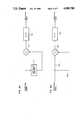
- FIG. 1is a block connection diagram of the main section of a transmitter in the first embodiment of the invention.
- reference numeral 1denotes a pseudo noise code generator to generate a pseudo noise code P(t);
- 2is a mixer to mix data D(t) to be transmitted and the output P(t) of the generator 1; 3 an oscillator to generate a reference frequency signal;
- 4a mixer to frequency convert a base band output of the mixer 2 by an output of the oscillator 3; 5 a 90° phase shifter to shift the phase of the reference frequency signal generated from the oscillator 3 by 90°;
- 6a mixer to frequency convert the output of the generator 1 by an output of the phase shifter 5;
- 7an adder to add outputs of the mixers 4 and 6;
- 8a band pass filter for allowing only the necessary frequency band in an output of the adder 7 to pass. It is assumed that each of the mixers 2, 4, and 6 performs double-phase modulation as a double balance mixer.
- the data D(t) to be transmittedis mixed by the mixer 2 with the pseudo noise code P(t) which is generated from the generator 1.
- the modulation signal of the mixer 2is further supplied to the mixer 4 and frequency converted by the reference frequency signal which is generated from the oscillator 3.
- the reference frequency signal of the oscillator 3is set to cos ⁇ t (where, ⁇ is an angular frequency which lies within a range from tens of MHz to hundreds of MHz)
- an output of the mixer 4becomes P(t) ⁇ D(t) ⁇ cos ⁇ t.
- the reference frequency signal cos ⁇ t of the oscillator 3is also sent to the 90° phase shifter 5 and is phase converted to -sin ⁇ t. Thereafter, the pseudo noise code transmitted from the generator 1 is frequency converted by the mixer 6 and the signal of -P(t) ⁇ sin ⁇ t is outputted.
- the adder 7adds the outputs of the mixers 4 and 6 and sends the signal of
- the band pass filter 8eliminates high frequency components, a DC component, noise, or the like which were caused in the mixers 2, 4, and 6 and transmits the resultant signal as the transmission signal to a receiver side through an antenna or a signal line.
- the transmitter of the embodimentafter the data to be transmitted was modulated by the pseudo noise code P(t) as the output of the pseudo noise code generator 1, it is frequency converted by the reference frequency by the oscillator 3 and 90° phase shifter 5.
- the cosine component including the pseudo noise code and the data and the sine component having only the pseudo noise codecan be synthesized and transmitted.
- the reference frequency signal of the oscillator 3has been transmitted to the mixer 4 and through the 90° phase shifter 5 to the mixer 6, respectively.
- the 90° phase shifter 5may be also arranged between the oscillator 3 and the mixer 4 instead of the position between the oscillator 3 and the mixer 6.
- FIG. 2is a block connection diagram of a main section of the transmitting system in the second embodiment of the invention.
- reference numeral 21denotes a pseudo noise code generator to generate the pseudo noise code P(t); 22 is an oscillator to generate a reference frequency signal; 23 a mixer to multiply the pseudo noise code P(t) which is generated from the generator 21 with the reference frequency signal which is generated from the oscillator 22; 24 a mixer to multiply an output of the mixer 23 with the data D(t) to be transmitted; 25 a 90° phase shifter to shift the phase of the reference frequency signal generated from the oscillator 22 by 90°; 26 a mixer to multiply the output of the generator 21 with an output of the phase shifter 25; 27 an adder to add outputs of the mixers 24 and 26; and 28 a band pass filter for allowing only the necessary frequency band in an output of the adder 27 to pass. It is assumed that each of the mixers 23, 24, and 26 performs the double-phase modulation as a double balance mixer.
- the pseudo noise code P(t) which is generated from the generator 21 and the reference frequency signal which is generated from the oscillator 22are multiplied by the mixer 23.
- the output of the mixer 23is further multiplied by the mixer 24 with the data D(t) to be transmitted.
- the reference frequency signal of the oscillator 22is cos ⁇ t (where, t is a time and ⁇ is the angular frequency which lies within a range from tens of MHz to hundreds of MHz)
- the output of the mixer 23becomes P(t) cos ⁇ t
- the output of the mixer 24becomes P(t) ⁇ D(t) cos ⁇ t.
- the reference frequency signal cos ⁇ t of the oscillator 22is also sent to the 90° phase shifter 25 and phase converted into -sin ⁇ t. Thereafter, it is multiplied with the pseudo noise code generated from the generator 21 by the mixer 26 and the signal of -P(t) ⁇ sin ⁇ t is outputted.
- the adder 27adds the outputs of the mixers 24 and 26 and transmits the signal of
- the band pass filter 28eliminates high frequency components, a DC component, noise, or the like which were caused in the mixers 23, 24, and 26 and transmits the resultant signal as the transmission signal to the receiver side through an antenna or a signal line.
- the cosine component including the pseudo noise code P(t) generated from the pseudo noise code generator 21 and the data D(t) to be transmitted and the sine component having only the same pseudo noise codecan be synthesized and transmitted.
- FIG. 3is a block connection diagram of a main section of a transmitter in the third embodiment of the invention.
- reference numeral 31denotes an oscillator to generate a reference frequency signal
- 32is a 90° phase shifter to shift the phase of the reference frequency signal generated from the oscillator 31 by 90°
- 32a mixer to frequency convert the data to be transmitted by an output of the oscillator 31
- 34a pseudo noise code generator to generate a pseudo noise code
- 35a mixer to modulate an output of the mixer 33 by the pseudo noise code as the output of the generator 34
- 36a mixer to frequency convert the output of the generator 34 by an output of the 90° phase shifter 32
- 37an adder to add outputs of the mixers 35 and 36
- 38a band pass filter for allowing only the necessary frequency band in an output of the adder 37 to pass. It is assumed that each of the mixers 33, 35, and 36 performs the double-phase modulation as a double balance mixer.
- the data D(t) to be transmittedis double-phase modulated by the mixer 33 by the reference frequency signal which is generated from the oscillator 31 and thereafter, it is modulated by the mixer 35 by the pseudo noise code P(t) which is generated from the generator 34.
- the reference frequency signal of the oscillator 31is cos ⁇ t (where, ⁇ is the angular frequency which lies within a range from tens a MHz to hundreds of MHz)
- the output of the mixer 35becomes P(t) ⁇ D(t) ⁇ cos ⁇ t.
- the reference frequency signal cos ⁇ t of the oscillator 31is also transmitted to the 90° phase shifter and phase converted into -sin ⁇ t. Thereafter, it is frequency converted by the mixer 36 by the false noise code P(t) which is generated from the generator 34, so that the signal of -P(t) ⁇ sin ⁇ is outputted.
- the adder 37adds the outputs of the mixers 35 and 36 and transmits the signal of
- the band pass filter 38eliminates high frequency components, a DC component, noise, or the like which were caused by the mixers 33, 35, and 36 and transmits the resultant signal as the transmission signal to the receiver side through an antenna or a signal line.
- the transmitter of this embodimentafter the data to be transmitted was frequency converted by the reference frequency which is generated from the oscillator 31, it is modulated by the pseudo noise code as the output of the pseudo noise code generator 34.
- the cosine component including the pseudo noise code and the data to be transmitted and the sine component having only the pseudo noise codeare synthesized and transmitted.
- the reference frequency signal of the oscillator 31has been transmitted to the mixer 33 and through the 90° phase shifter 32 to the mixer 36.
- the 90° phase shifter 32may be also arranged between the oscillator 31 and the mixer 33 instead of the position between the oscillator 31 and the mixer 36.
- FIG. 4Ashows a block connection diagram of a main section of the receiver in the first embodiment of the invention.
- reference numeral 41denotes a 90° phase shifter to shift the phase of the reception signal by 90°
- 42is mixer to multiply the reception signal with an output of the 90° phase shifter 41
- 43a band pass filter for allowing only the component including the transmission data in an output of the mixer 42 to pass.
- the signal of the equation (1) which was transmitted from each of the transmitters shown in FIGS. 1, 2 and 3is transmitted as a reception signal to the 90° phase shifter 41 and phase converted to the following equation (2).
- the mixer 42multiplies the equations (1) and (2), so that the output of the mixer 42 becomes
- the band pass filter 43eliminates the DC component or high frequency component which is caused due to the non-linearity of the mixer 42 and allows only -D(t) cos 2 ⁇ t including the transmission data D(t) to pass.
- -D(t) ⁇ cos 2 ⁇ tis the signal which was double-phase modulated by the transmission data D(t) at the frequency of 2 ⁇ /2 ⁇ and does not include the pseudo noise code P(t) which was used for the spectrum spread. Therefore, to demodulate the transmission data D(t) from the equation (4), it can be easily demodulated by the well-known means (for example, costas loop demodulation, bit delay detection, or the like) for demodulating the double-phase modulated signal.
- the transmission data D(t) which was modulated by the transmitters in FIGS. 1 to 3is demodulated by the receiver of FIG. 4A as explained above.
- the explanationhas been made on the assumption that the transmission signal from each of the band pass filters 8, 28, and 38 in FIGS. 1 to 3 is directly received by the receiving system of FIG. 4A.
- the angular frequency ⁇ shown in the equations (2), (3), and (4)is converted into the intermediate frequency ⁇ '.
- the signal which is obtained from the band pass filter 43is FIG. 4A is also equal to -D(t) cos -2 ⁇ t, so that no problem occurs.
- the band pass filter 43can be also omitted.
- FIG. 4Bshows a block connection diagram of a main section of the receiver in the second embodiment of the invention.
- reference numeral 42denotes the mixer to multiply reception signals which are transmitted from both lines 40a and 40b; and 43 indicates the band pass filter for allowing only the component including the transmission data in an output of the mixer 42 to pass.
- FIG. 4B receiverThe operation of the FIG. 4B receiver will now be described hereinbelow.
- the band pass filter 43allows only
- This signalis the signal which was double-phase modulated by the transmission data D(t) by the center frequency 2 ⁇ /2 ⁇ and does not include the pseudo noise code P(t) which was used for the spread of spectrum. Since the equation (7) indicates the double-phase modulation signal, in order to demodulate the transmission data D(t) from this equation, it can be easily demodulated by well-known means (for example, costas loop demodulation, bit delay detection, or the like) for demodulating the double-phase modulated signal. Therefore, the transmission data D(t) which was modulated by each of the transmitters of FIGS. 1, 2 and 3 is demodulated by the receiving system of FIG. 4B.
- FIG. 5shows a block connection diagram of a main section of the receiver in the third embodiment of the invention.
- reference numeral 51denotes a voltage controlled oscillator to generate a frequency which is almost equal to the frequency which is generated by the oscillator 3 or 22 in the transmitter;
- 52is a mixer to multiply the reception signal with an output of the oscillator 51;
- 53a 90° phase shifter to shift the phase of the output of the oscillator 51 by 90°;
- 54a mixer to multiply the reception signal with an output of the 90° phase shifter 53;
- 55a low pass filter for allowing only the low frequency component in an output of the mixer 52 to pass;
- 56a low pass filter for allowing the low frequency component in an output of the mixer 54 to pass;
- 57an adder to add outputs of the low pass filters 55 and 56;
- 58an adder to subtract the output of the low pass filter 56 from the output of the low pass filter 55;
- 59a mixer to multiply an output of the adder 57 with an output of the adder 58;
- 60a mixer to multiply the output of the low pass filter 55
- FIG. 5 receiverThe operation of the FIG. 5 receiver will now be described hereinbelow.
- phase of the output of the oscillator 51is shifted by 90° by the 90° phase shifter 53 and becomes
- the output R 2 ' of the low pass filter 55 and the output R 3 ' of the low pass filter 56are multiplied by the mixer 60, so that an output R 7 is obtained.
- the output R 7is further processed by the low pass filter 62, so that a signal R 7 ' is derived.
- the output R 8 of the mixer 63is amplified by the amplifier 64 and the frequency band is limited by the loop filter 65 as necessary.
- the resultant signalis supplied to the voltage controlled oscillator 51, thereby controlling the oscillator 51 so that ⁇ .sub.(t) in the equation (21) becomes
- the output R 7 ' of the low pass filter 62becomes as follows by the equations (19) and (22). ##EQU12## This is the same as the transmission data. Namely, the transmission data D(t) which was modulated by each of the transmitters in FIGS. 1, 2 and 3 is demodulated by the receiver of FIG. 5.
- the signal obtained from the low pass filter 62 in FIG. 5is also equal to D(t)/4 and no problem occurs.
- the low pass filters 61 and 62can be also omitted. Further, when the output level of the mixer 62 is enough high, the amplifier 64 can be also omitted.
Landscapes
- Engineering & Computer Science (AREA)
- Computer Networks & Wireless Communication (AREA)
- Signal Processing (AREA)
- Transceivers (AREA)
Abstract
Description
P(t)·D(t)·cos ωt-P(t)·sin ωt (1)
P(t)·D(t)·cos ω-P(t)·sin ωt (1)
P(t)·D(t)·cos ω-P(t)·sin ωt (1)
-P(t)·D(t)·sin ωt-P(t)·cos ωt (2)
-P(t).sup.2 ·D(t).sup.2 ·sin ωt·cos ωt+P(t).sup.2 ·sin ωt cos ωt+P(t).sup.2 ·D(t)·sin.sup.2 ωt-P(t).sup.2 ·D(t)·cos.sup.2 ωt (3)
-D(t) (cos.sup.2 ωt-sin.sup.2 ωt)=-D(t) cos 2ωt (4)
P(t).sup.2 ·D(t).sup.2 cos.sup.2 ωt+P(t).sup.2 sin.sup.2 ωt-2P(t).sup.2 ·D(t)·sin ωt·cos ωt (5)
1-D(t) sin 2ωt (6)
-D(t) sin 2ωt (7)
cos (ωt+θ.sub.(t)) (8)
-sin (ωt+θ.sub.(t)) (11)
θ.sub.(t) =0 (22)
Claims (6)
Applications Claiming Priority (10)
| Application Number | Priority Date | Filing Date | Title |
|---|---|---|---|
| JP61-277197 | 1986-11-20 | ||
| JP61-277216 | 1986-11-20 | ||
| JP61277197AJPS63131630A (en) | 1986-11-20 | 1986-11-20 | Transmission equipment |
| JP61277216AJPS63131631A (en) | 1986-11-20 | 1986-11-20 | Transmission equipment |
| JP62-114153 | 1987-05-11 | ||
| JP62-114152 | 1987-05-11 | ||
| JP62114153AJPH07105744B2 (en) | 1986-11-20 | 1987-05-11 | Transmission / reception system |
| JP62114152AJPH07105743B2 (en) | 1986-11-20 | 1987-05-11 | Transmitter and receiver thereof |
| JP62-167217 | 1987-07-03 | ||
| JP62167217AJPH0779280B2 (en) | 1987-07-03 | 1987-07-03 | Receiver |
Publications (1)
| Publication Number | Publication Date |
|---|---|
| US4888788Atrue US4888788A (en) | 1989-12-19 |
Family
ID=27526626
Family Applications (1)
| Application Number | Title | Priority Date | Filing Date |
|---|---|---|---|
| US07/121,101Expired - LifetimeUS4888788A (en) | 1986-11-20 | 1987-11-16 | Transmitting and receiving systems |
Country Status (1)
| Country | Link |
|---|---|
| US (1) | US4888788A (en) |
Cited By (29)
| Publication number | Priority date | Publication date | Assignee | Title |
|---|---|---|---|---|
| US4993044A (en)* | 1988-09-02 | 1991-02-12 | Clarion Co., Ltd. | Spread-spectrum communication receiver |
| US5159607A (en)* | 1990-02-16 | 1992-10-27 | Stc Plc | Rf signal synthesis |
| US5222099A (en)* | 1991-01-21 | 1993-06-22 | Sony Corporation | Spread spectrum signal receiving apparatus |
| US5263055A (en)* | 1991-11-04 | 1993-11-16 | Motorola, Inc. | Apparatus and method for reducing harmonic interference generated by a clock signal |
| EP0639009A1 (en)* | 1993-08-13 | 1995-02-15 | Matra Communication | Method and device for transmission in CDMA radio communications |
| US5400359A (en)* | 1992-03-23 | 1995-03-21 | Sharp Kabushiki Kaisha | Spread spectrum communication system and an apparatus for communication utilizing this system |
| US5423001A (en)* | 1989-11-07 | 1995-06-06 | Daikin Industries, Ltd. | Data transmission and apparatus, data processing apparatus and a neural network which utilize phase shifted, modulated, convolutable pseudo noise |
| US5544223A (en)* | 1995-01-31 | 1996-08-06 | Qualcomm Incorporated | Method and apparatus for paging a concentrated subscriber system for wireless local loop |
| US5602833A (en)* | 1994-12-19 | 1997-02-11 | Qualcomm Incorporated | Method and apparatus for using Walsh shift keying in a spread spectrum communication system |
| US5608722A (en)* | 1995-04-03 | 1997-03-04 | Qualcomm Incorporated | Multi-user communication system architecture with distributed receivers |
| US5691974A (en)* | 1995-01-04 | 1997-11-25 | Qualcomm Incorporated | Method and apparatus for using full spectrum transmitted power in a spread spectrum communication system for tracking individual recipient phase, time and energy |
| US5757767A (en)* | 1995-04-18 | 1998-05-26 | Qualcomm Incorporated | Method and apparatus for joint transmission of multiple data signals in spread spectrum communication systems |
| US5781856A (en)* | 1995-01-31 | 1998-07-14 | Qualcomm Incorporated | Concentrated subscriber system for wireless local loop |
| US5812940A (en)* | 1994-04-21 | 1998-09-22 | Ericsson Inc. | Reducing interference from oscillators in electronic equipment |
| US6061388A (en)* | 1996-06-07 | 2000-05-09 | General Electric Company | Spread spectrum communication system with frequency-separated message and reference signals |
| US20020131480A1 (en)* | 2000-10-24 | 2002-09-19 | Sousa Elvino S. | Spread spectrum receiver |
| US6510172B1 (en) | 1997-03-04 | 2003-01-21 | Qualcomm, Inc. | Multi-user communication system architecture with distributed transmitters |
| EP0871298A3 (en)* | 1997-04-09 | 2003-03-26 | Yozan, Inc. | Complex despreading receiver |
| US6560291B1 (en)* | 1998-04-01 | 2003-05-06 | Canon Kabushiki Kaisha | Device and method for transmitting information and device and method for receiving information |
| US20040001533A1 (en)* | 2002-02-04 | 2004-01-01 | Tran Tranh T. | Method and system of reducing electromagnetic interference emissions |
| US20040066840A1 (en)* | 1993-11-02 | 2004-04-08 | Interdigital Technology Corporation | Noise shaping technique for spread spectrum communications |
| US20050105591A1 (en)* | 2003-02-28 | 2005-05-19 | Xemi, Inc. | Noise source synchronization for power spread signals |
| US20070103204A1 (en)* | 2005-11-10 | 2007-05-10 | X-Emi, Inc. | Method and apparatus for conversion between quasi differential signaling and true differential signaling |
| US20080250175A1 (en)* | 2007-04-03 | 2008-10-09 | Vizionware, Inc. | Cable assembly having an adaptive two-wire bus |
| US20080247414A1 (en)* | 2007-04-03 | 2008-10-09 | Vizionware, Inc. | Clock stretching in an adaptive two-wire bus |
| US20080250170A1 (en)* | 2007-04-03 | 2008-10-09 | Vizionware, Inc. | Clock mode detection in an adaptive two-wire bus |
| US20080250184A1 (en)* | 2007-04-03 | 2008-10-09 | Vizionware, Inc. | Adaptive two-wire bus |
| US20080246626A1 (en)* | 2007-04-03 | 2008-10-09 | Vizionware, Inc. | Data transaction direction detection in an adaptive two-wire bus |
| US20090122775A1 (en)* | 2002-09-20 | 2009-05-14 | Jacobus Haartsen | Methods and electronic devices for wireless ad-hoc network communications using receiver determined channels and transmitted reference signals |
Citations (12)
| Publication number | Priority date | Publication date | Assignee | Title |
|---|---|---|---|---|
| US4017798A (en)* | 1975-09-08 | 1977-04-12 | Ncr Corporation | Spread spectrum demodulator |
| US4039749A (en)* | 1975-09-08 | 1977-08-02 | Ncr Corporation | Spread spectrum demodulator |
| US4327438A (en)* | 1978-12-19 | 1982-04-27 | Siemens Aktiengesellschaft | Receiving circuit in an interference-suppressing communications system comprising narrow-band conventional message modulation and additional pseudo-noise phase shift keying |
| US4470145A (en)* | 1982-07-26 | 1984-09-04 | Hughes Aircraft Company | Single sideband quadricorrelator |
| US4485477A (en)* | 1982-07-19 | 1984-11-27 | Rca Corporation | Fast frequency/code search |
| US4528674A (en)* | 1983-08-22 | 1985-07-09 | E-Systems, Inc. | Method and apparatus for baseband generation of a spread spectrum reference signal for use in an LMS adaptive array processor |
| US4607375A (en)* | 1984-10-17 | 1986-08-19 | Itt Corporation | Covert communication system |
| US4651327A (en)* | 1984-10-12 | 1987-03-17 | Sony Corporation | Decoder for spectrum diffusion signals |
| US4706093A (en)* | 1984-03-26 | 1987-11-10 | Motorola, Inc. | Monopulse tracking system substantially free of externally generated noise |
| US4736390A (en)* | 1986-10-15 | 1988-04-05 | Itt Avionics, A Division Of Itt Corporation | Zero IF radio receiver apparatus |
| US4760586A (en)* | 1984-12-29 | 1988-07-26 | Kyocera Corporation | Spread spectrum communication system |
| US4774716A (en)* | 1986-01-22 | 1988-09-27 | Bbc Brown, Boveri & Company, Limited | Method for the transmission of digital data |
- 1987
- 1987-11-16USUS07/121,101patent/US4888788A/ennot_activeExpired - Lifetime
Patent Citations (12)
| Publication number | Priority date | Publication date | Assignee | Title |
|---|---|---|---|---|
| US4017798A (en)* | 1975-09-08 | 1977-04-12 | Ncr Corporation | Spread spectrum demodulator |
| US4039749A (en)* | 1975-09-08 | 1977-08-02 | Ncr Corporation | Spread spectrum demodulator |
| US4327438A (en)* | 1978-12-19 | 1982-04-27 | Siemens Aktiengesellschaft | Receiving circuit in an interference-suppressing communications system comprising narrow-band conventional message modulation and additional pseudo-noise phase shift keying |
| US4485477A (en)* | 1982-07-19 | 1984-11-27 | Rca Corporation | Fast frequency/code search |
| US4470145A (en)* | 1982-07-26 | 1984-09-04 | Hughes Aircraft Company | Single sideband quadricorrelator |
| US4528674A (en)* | 1983-08-22 | 1985-07-09 | E-Systems, Inc. | Method and apparatus for baseband generation of a spread spectrum reference signal for use in an LMS adaptive array processor |
| US4706093A (en)* | 1984-03-26 | 1987-11-10 | Motorola, Inc. | Monopulse tracking system substantially free of externally generated noise |
| US4651327A (en)* | 1984-10-12 | 1987-03-17 | Sony Corporation | Decoder for spectrum diffusion signals |
| US4607375A (en)* | 1984-10-17 | 1986-08-19 | Itt Corporation | Covert communication system |
| US4760586A (en)* | 1984-12-29 | 1988-07-26 | Kyocera Corporation | Spread spectrum communication system |
| US4774716A (en)* | 1986-01-22 | 1988-09-27 | Bbc Brown, Boveri & Company, Limited | Method for the transmission of digital data |
| US4736390A (en)* | 1986-10-15 | 1988-04-05 | Itt Avionics, A Division Of Itt Corporation | Zero IF radio receiver apparatus |
Non-Patent Citations (2)
| Title |
|---|
| Spread Spectrum System R.C. Dixon, John Wiley & Sons Inc., 1976, pp. 206 215.* |
| Spread Spectrum System-R.C. Dixon, John Wiley & Sons Inc., 1976, pp. 206-215. |
Cited By (45)
| Publication number | Priority date | Publication date | Assignee | Title |
|---|---|---|---|---|
| US4993044A (en)* | 1988-09-02 | 1991-02-12 | Clarion Co., Ltd. | Spread-spectrum communication receiver |
| US5423001A (en)* | 1989-11-07 | 1995-06-06 | Daikin Industries, Ltd. | Data transmission and apparatus, data processing apparatus and a neural network which utilize phase shifted, modulated, convolutable pseudo noise |
| US5159607A (en)* | 1990-02-16 | 1992-10-27 | Stc Plc | Rf signal synthesis |
| EP0442611A3 (en)* | 1990-02-16 | 1993-01-13 | Stc Plc | Rf signal synthesis |
| US5222099A (en)* | 1991-01-21 | 1993-06-22 | Sony Corporation | Spread spectrum signal receiving apparatus |
| US5263055A (en)* | 1991-11-04 | 1993-11-16 | Motorola, Inc. | Apparatus and method for reducing harmonic interference generated by a clock signal |
| US5400359A (en)* | 1992-03-23 | 1995-03-21 | Sharp Kabushiki Kaisha | Spread spectrum communication system and an apparatus for communication utilizing this system |
| FR2709029A1 (en)* | 1993-08-13 | 1995-02-17 | Matra Communication | Transmission method for CDMA radio communications and devices for its implementation. |
| EP0639009A1 (en)* | 1993-08-13 | 1995-02-15 | Matra Communication | Method and device for transmission in CDMA radio communications |
| US5544167A (en)* | 1993-08-13 | 1996-08-06 | Matra Communication | Transmission method for CDMA radiotelephone communications, and apparatuses for implementing such method |
| US7099373B2 (en)* | 1993-11-02 | 2006-08-29 | Interdigital Technology Corporation | Noise shaping technique for spread spectrum communications |
| US20060284669A1 (en)* | 1993-11-02 | 2006-12-21 | Interdigital Technology Corporation | Noise shaping technique for spread spectrum communications |
| US7440486B2 (en) | 1993-11-02 | 2008-10-21 | Interdigital Technology Corporation | Noise shaping technique for spread spectrum communications |
| US20040066840A1 (en)* | 1993-11-02 | 2004-04-08 | Interdigital Technology Corporation | Noise shaping technique for spread spectrum communications |
| US5812940A (en)* | 1994-04-21 | 1998-09-22 | Ericsson Inc. | Reducing interference from oscillators in electronic equipment |
| US5602833A (en)* | 1994-12-19 | 1997-02-11 | Qualcomm Incorporated | Method and apparatus for using Walsh shift keying in a spread spectrum communication system |
| US5691974A (en)* | 1995-01-04 | 1997-11-25 | Qualcomm Incorporated | Method and apparatus for using full spectrum transmitted power in a spread spectrum communication system for tracking individual recipient phase, time and energy |
| US5544223A (en)* | 1995-01-31 | 1996-08-06 | Qualcomm Incorporated | Method and apparatus for paging a concentrated subscriber system for wireless local loop |
| US5781856A (en)* | 1995-01-31 | 1998-07-14 | Qualcomm Incorporated | Concentrated subscriber system for wireless local loop |
| US5608722A (en)* | 1995-04-03 | 1997-03-04 | Qualcomm Incorporated | Multi-user communication system architecture with distributed receivers |
| US5757767A (en)* | 1995-04-18 | 1998-05-26 | Qualcomm Incorporated | Method and apparatus for joint transmission of multiple data signals in spread spectrum communication systems |
| US6061388A (en)* | 1996-06-07 | 2000-05-09 | General Electric Company | Spread spectrum communication system with frequency-separated message and reference signals |
| US6510172B1 (en) | 1997-03-04 | 2003-01-21 | Qualcomm, Inc. | Multi-user communication system architecture with distributed transmitters |
| EP0871298A3 (en)* | 1997-04-09 | 2003-03-26 | Yozan, Inc. | Complex despreading receiver |
| US6560291B1 (en)* | 1998-04-01 | 2003-05-06 | Canon Kabushiki Kaisha | Device and method for transmitting information and device and method for receiving information |
| US20020131480A1 (en)* | 2000-10-24 | 2002-09-19 | Sousa Elvino S. | Spread spectrum receiver |
| US7010022B2 (en)* | 2000-10-24 | 2006-03-07 | Sony Corporation | Spread spectrum receiver |
| US20040001533A1 (en)* | 2002-02-04 | 2004-01-01 | Tran Tranh T. | Method and system of reducing electromagnetic interference emissions |
| US20050105592A1 (en)* | 2002-02-04 | 2005-05-19 | Xemi, Inc. | Reduced EMI using multiple noise sources |
| US20050105590A1 (en)* | 2002-02-04 | 2005-05-19 | Xemi, Inc. | Reduction EMI using transmission offsets |
| US20050100080A1 (en)* | 2002-02-04 | 2005-05-12 | Xemi, Inc. | Reduced EMI in parallel transmissions |
| US20050084021A1 (en)* | 2002-02-04 | 2005-04-21 | Xemi, Inc. | Reduced EMI device and method thereof |
| US7305020B2 (en) | 2002-02-04 | 2007-12-04 | Vizionware, Inc. | Method and system of reducing electromagnetic interference emissions |
| US20090122775A1 (en)* | 2002-09-20 | 2009-05-14 | Jacobus Haartsen | Methods and electronic devices for wireless ad-hoc network communications using receiver determined channels and transmitted reference signals |
| US20050105591A1 (en)* | 2003-02-28 | 2005-05-19 | Xemi, Inc. | Noise source synchronization for power spread signals |
| US20070206640A1 (en)* | 2005-11-10 | 2007-09-06 | X-Emi, Inc. | Active signal management in cables and other interconnects |
| US20070206642A1 (en)* | 2005-11-10 | 2007-09-06 | X-Emi, Inc. | Bidirectional active signal management in cables and other interconnects |
| US20070206641A1 (en)* | 2005-11-10 | 2007-09-06 | X-Emi, Inc. | Encoding and deserialization-serialization for digital signals |
| US20070206643A1 (en)* | 2005-11-10 | 2007-09-06 | X-Emi, Inc. | Skew management in cables and other interconnects |
| US20070103204A1 (en)* | 2005-11-10 | 2007-05-10 | X-Emi, Inc. | Method and apparatus for conversion between quasi differential signaling and true differential signaling |
| US20080250175A1 (en)* | 2007-04-03 | 2008-10-09 | Vizionware, Inc. | Cable assembly having an adaptive two-wire bus |
| US20080247414A1 (en)* | 2007-04-03 | 2008-10-09 | Vizionware, Inc. | Clock stretching in an adaptive two-wire bus |
| US20080250170A1 (en)* | 2007-04-03 | 2008-10-09 | Vizionware, Inc. | Clock mode detection in an adaptive two-wire bus |
| US20080250184A1 (en)* | 2007-04-03 | 2008-10-09 | Vizionware, Inc. | Adaptive two-wire bus |
| US20080246626A1 (en)* | 2007-04-03 | 2008-10-09 | Vizionware, Inc. | Data transaction direction detection in an adaptive two-wire bus |
Similar Documents
| Publication | Publication Date | Title |
|---|---|---|
| US4888788A (en) | Transmitting and receiving systems | |
| KR960003786B1 (en) | Baseband Phase Modulator Device Using Digital Technology | |
| US5495500A (en) | Homodyne radio architecture for direct sequence spread spectrum data reception | |
| US4912722A (en) | Self-synchronous spread spectrum transmitter/receiver | |
| US5771442A (en) | Dual mode transmitter | |
| KR100363760B1 (en) | Local oscillator phase noise cancelling modulation technique | |
| CA1082313A (en) | Transmitter/receivers | |
| US5937335A (en) | Transmission and reception apparatus having a single phase-locked loop and method thereof | |
| US4475243A (en) | Isolation method and apparatus for a same frequency repeater | |
| EP0329186B1 (en) | Polarization diversity optical receiver for coherent optical communication | |
| US4789993A (en) | One frequency repeater for a digital radio system | |
| US5241566A (en) | Full duplex FSK system | |
| US4852123A (en) | Nearly DC IF phase locked transceiver | |
| US4527276A (en) | Digital pulse position modulation communications system with threshold extension | |
| US5126998A (en) | Method and apparatus for transmitting and receiving a carrier signal which is simultaneously frequency and phase modulated | |
| US5638401A (en) | Method and apparatus for generating plural quadrature modulated carriers | |
| US5661757A (en) | Radio-card communication system | |
| US4149121A (en) | Four phase to two phase correlator | |
| GB2236225A (en) | Superhetorodyne circuit | |
| Costas | Synchronous communications | |
| JP3287015B2 (en) | Auxiliary signal transmission method | |
| JPH05268188A (en) | Multiple wireless modem | |
| US5134721A (en) | Noise eliminating device for angle-modulated wave | |
| JPS63131631A (en) | Transmission equipment | |
| US3383597A (en) | Multiple access satellite communication system |
Legal Events
| Date | Code | Title | Description |
|---|---|---|---|
| AS | Assignment | Owner name:MATSUSHITA ELECTRIC INUDUSTRIAL CO., LTD., 1006, O Free format text:ASSIGNMENT OF ASSIGNORS INTEREST.;ASSIGNORS:TERANISHI, AKIO;GENJI, NOBUO;ITOH, KOHJI;REEL/FRAME:004830/0077 Effective date:19871201 Owner name:MATSUSHITA ELECTRIC INUDUSTRIAL CO., LTD., A CORP Free format text:ASSIGNMENT OF ASSIGNORS INTEREST;ASSIGNORS:TERANISHI, AKIO;GENJI, NOBUO;ITOH, KOHJI;REEL/FRAME:004830/0077 Effective date:19871201 | |
| STCF | Information on status: patent grant | Free format text:PATENTED CASE | |
| FEPP | Fee payment procedure | Free format text:PAYOR NUMBER ASSIGNED (ORIGINAL EVENT CODE: ASPN); ENTITY STATUS OF PATENT OWNER: LARGE ENTITY | |
| FPAY | Fee payment | Year of fee payment:4 | |
| FEPP | Fee payment procedure | Free format text:PAYER NUMBER DE-ASSIGNED (ORIGINAL EVENT CODE: RMPN); ENTITY STATUS OF PATENT OWNER: LARGE ENTITY Free format text:PAYOR NUMBER ASSIGNED (ORIGINAL EVENT CODE: ASPN); ENTITY STATUS OF PATENT OWNER: LARGE ENTITY | |
| FPAY | Fee payment | Year of fee payment:8 | |
| FPAY | Fee payment | Year of fee payment:12 |