US4888702A - Photovoltaic system controller - Google Patents
Photovoltaic system controllerDownload PDFInfo
- Publication number
- US4888702A US4888702AUS07/087,314US8731487AUS4888702AUS 4888702 AUS4888702 AUS 4888702AUS 8731487 AUS8731487 AUS 8731487AUS 4888702 AUS4888702 AUS 4888702A
- Authority
- US
- United States
- Prior art keywords
- microprocessor
- controller
- setpoint
- battery
- load
- Prior art date
- Legal status (The legal status is an assumption and is not a legal conclusion. Google has not performed a legal analysis and makes no representation as to the accuracy of the status listed.)
- Expired - Lifetime
Links
- 229910052751metalInorganic materials0.000claimsdescription7
- 239000002184metalSubstances0.000claimsdescription7
- 230000000694effectsEffects0.000claimsdescription6
- 230000004044responseEffects0.000claimsdescription6
- 238000006073displacement reactionMethods0.000claimsdescription5
- QSHDDOUJBYECFT-UHFFFAOYSA-NmercuryChemical compound[Hg]QSHDDOUJBYECFT-UHFFFAOYSA-N0.000claimsdescription5
- 229910052753mercuryInorganic materials0.000claimsdescription5
- 238000010079rubber tappingMethods0.000claimsdescription2
- 238000000034methodMethods0.000claims3
- 238000011156evaluationMethods0.000claims2
- 238000002955isolationMethods0.000claims2
- 230000000007visual effectEffects0.000claims2
- 230000006870functionEffects0.000abstractdescription25
- 238000013461designMethods0.000abstractdescription7
- 238000001228spectrumMethods0.000abstractdescription2
- 238000009434installationMethods0.000description6
- 230000001105regulatory effectEffects0.000description6
- 238000012544monitoring processMethods0.000description5
- 238000004353relayed correlation spectroscopyMethods0.000description5
- 239000000446fuelSubstances0.000description4
- CYTYCFOTNPOANT-UHFFFAOYSA-NPerchloroethyleneChemical compoundClC(Cl)=C(Cl)ClCYTYCFOTNPOANT-UHFFFAOYSA-N0.000description3
- 239000007787solidSubstances0.000description3
- 230000001052transient effectEffects0.000description3
- 230000002411adverseEffects0.000description2
- 238000004364calculation methodMethods0.000description2
- 230000001276controlling effectEffects0.000description2
- 230000006378damageEffects0.000description2
- 230000000994depressogenic effectEffects0.000description2
- 238000010586diagramMethods0.000description2
- 238000007599dischargingMethods0.000description2
- 238000005259measurementMethods0.000description2
- 230000003071parasitic effectEffects0.000description2
- 229910001220stainless steelInorganic materials0.000description2
- 239000010935stainless steelSubstances0.000description2
- 229910000831SteelInorganic materials0.000description1
- 230000003213activating effectEffects0.000description1
- 230000004397blinkingEffects0.000description1
- 230000000881depressing effectEffects0.000description1
- 230000007613environmental effectEffects0.000description1
- 238000003780insertionMethods0.000description1
- 230000037431insertionEffects0.000description1
- 238000012423maintenanceMethods0.000description1
- 230000005055memory storageEffects0.000description1
- 231100000989no adverse effectToxicity0.000description1
- 230000000737periodic effectEffects0.000description1
- 230000005855radiationEffects0.000description1
- 239000010959steelSubstances0.000description1
- 239000013589supplementSubstances0.000description1
Images


Classifications
- H—ELECTRICITY
- H02—GENERATION; CONVERSION OR DISTRIBUTION OF ELECTRIC POWER
- H02J—CIRCUIT ARRANGEMENTS OR SYSTEMS FOR SUPPLYING OR DISTRIBUTING ELECTRIC POWER; SYSTEMS FOR STORING ELECTRIC ENERGY
- H02J7/00—Circuit arrangements for charging or depolarising batteries or for supplying loads from batteries
- H02J7/34—Parallel operation in networks using both storage and other DC sources, e.g. providing buffering
- H02J7/35—Parallel operation in networks using both storage and other DC sources, e.g. providing buffering with light sensitive cells
- Y—GENERAL TAGGING OF NEW TECHNOLOGICAL DEVELOPMENTS; GENERAL TAGGING OF CROSS-SECTIONAL TECHNOLOGIES SPANNING OVER SEVERAL SECTIONS OF THE IPC; TECHNICAL SUBJECTS COVERED BY FORMER USPC CROSS-REFERENCE ART COLLECTIONS [XRACs] AND DIGESTS
- Y02—TECHNOLOGIES OR APPLICATIONS FOR MITIGATION OR ADAPTATION AGAINST CLIMATE CHANGE
- Y02E—REDUCTION OF GREENHOUSE GAS [GHG] EMISSIONS, RELATED TO ENERGY GENERATION, TRANSMISSION OR DISTRIBUTION
- Y02E10/00—Energy generation through renewable energy sources
- Y02E10/50—Photovoltaic [PV] energy
- Y02E10/56—Power conversion systems, e.g. maximum power point trackers
Definitions
- the inventionpertains generally to a controller for monitoring and regulating photovoltaic (PV) power systems, ranging from relatively simple stand-alone PV power systems to larger PV/fuel generator hybrid power systems. More particularly, the invention is directed to a microprocessor-based programmable controller which is specifically designed for utilization at unattended system installations in remote sites with harsh environments, and which effectively achieves optimum charging of the system batteries by the photovoltaic array and/or the auxiliary generator.
- the controlleris specifically adapted to regulate the PV array, to control the auxiliary generator, to manage the system load, to monitor and display system parameters and to energize an alarm in response to the occurence of certain critical system conditions.
- the controlleraccomplishes the foregoing functions by means of a microprocessor having a control algorithm which is uniquely capable of being redefined to accommodate new and diverse PV system control schemes.
- the stand-alone PV power systemtypically includes a PV array comprising an assembly of solar photovoltaic cells connected in a series parallel configuration, and a system battery comprising a block of batteries which are charged by current from the PV array to serve as the primary power source for a load.
- system efficiencydictates that the battery receive the maximum possible amount of charge, it is essential to accurately regulate the PV array in order to prevent battery overcharge with its associated excess gassing and potential destruction of the battery.
- the batteryrepresents a very costly and sensitive component in the PV power system, the importance of successful and precise regulation of battery charge is even further intensified.
- the controller of the present inventioninitiates charge regulation for the battery when the system voltage reaches a predetermined level, being adapted to disconnect the array from the battery so as to allow the system voltage to fall to a more desirable level.
- the controlleris adapted to effect reconnection of the array to resume battery charging.
- the controlleris thus capable of insuring optimum battery charging and maximization of battery life.
- the subject controllerprovides such a mechanism by accomplishing disconnection of the load from the battery at a predetermined system voltage in order to interrupt the battery discharge mode.
- the load disconnect function of the controllerpossesses a built-in time delay feature that prevents nuisance disconnections. Once disconnected, the load is adapted to remain disconnected until a higher system voltage setpoint is reached, at which time the controller effects reconnection of the batteries to the load.
- the typical hybrid power systemincludes, in addition to the PV array, battery and load, a fuel consumable Thermo Electric Generator (TEG) or Diesel Electric Generator (DEG).
- TEGThermo Electric Generator
- DEGDiesel Electric Generator
- the latter generatorsmay be utilized to charge the system battery as a supplement to the PV array when the array is deliberately undersized, when the array fails to maintain a desired system voltage, or as a function of the ambient temperature of the system, to serve as a back-up for the PV array in the event of a system failure or to directly power the load, as dictated by design requirements.
- the controller of the present inventionis able to control operation of a generator to maintain the desired battery state of charge or in response to other diverse system conditions. Typically, the controller will initiate operation of a generator when the battery voltage falls to a predetermined setpoint. Once the controller has caused the generator to be turned on, the generator generally will remain on until the battery voltage, as determined by the microprocessor, reaches a higher predetermined level.
- All of the control functions of the present controllerare based upon the temperature compensated system voltage. Similarly, all of the controller functions are corrected for temperature by means of a coefficient incorporated into the control algorithm.
- the applicable compensation coefficientis adapted to be adjusted in the field to one from a range of available coefficients by setting a DIP switch. The controller thus effectively accommodates the fact that battery characteristics, including voltage, vary with ambient temperature, and age, thereby resulting in superior accuracy of control and operation.
- all of the foregoing setpointsnamely, the array disconnect and reconnect setpoints, the load disconnect and reconnect setpoints and the generator start and stop setpoints, are adapted for easy adjustment in the field over a wide range by means of a bank of DIP switches, so as to accommodate an entire spectrum of system operating parameters.
- the subject photovoltaic system controlleris further adapted to monitor system status, being capable of performing continuous system diagnostic functions.
- the controllermay be provided with an annunciator panel including LED system status indicators, as well as a digital meter for reading voltages, currents and temperatures.
- the indicatorsmay selectively display "normal" system status, i.e. normal charging or discharging of the battery; system voltage; array, load and battery currents; and ambient temperature.
- the display systemis particularly designed to require only a small amount of power.
- the photovoltaic system controlleris capable of providing an alarm when the system voltage falls below a field adjustable low alarm setpoint.
- the controlleris adapted to light an alarm LED, and is able to send a signal which may activate an external alarm.
- the foregoing capabilitiesare provided by the logic unit of the controller, wherein processor-based design provides powerful, flexible control and capability.
- the control algorithm for the logic unitis characterized by non-volatile memory storage to insure that system operation returns to normal following any loss of, or temporary drop in, system voltage below the minimum required for controller operation.
- the control algorithmmay be easily redefined merely by replacing the erasable programmable memory component.
- the controlleris thus able to be adapted to standard as well as custom programming to afford a broad variety of system applications.
- the controllerincorporates digital circuitry which does not require periodic adjustments or alignments in order to maintain control accuracy. Also included is an emergency back-up control, comprising analog circuits, for the array and load relays in the event of loss of main controller function. Moreover, the controller's memory, logic functions, data/control bus, and input/output ports are all integral to a single circuit, thus providing advantageously for fewer parts. A further unique characteristic is that the controller derives its operating power from the system battery.
- the controlleris designed in conformance with commercial and military standards, and is adapted for use over long periods.
- the logic unitis enclosed in a heavy steel casing which is easy to install and which is able to shield against transient surges.
- the controlleris uniquely suited to withstand the vibration and noise conditions typical of diesel generator installations, as well as the harsh physical environments typical of remote site applications.
- the controlleris able to realize an efficiency rating better than 99% while being adapted for utilization by relatively unskilled personnel.
- U.S. Pat. No. 4,327,318 to Kwon et alteaches a source shedding voltage regulator which selectively sheds portions of the PV array into or from the charging system by switching means in response to the terminal voltage of the storage battery.
- Voltage monitoring meanscompares the terminal voltage to a predetermined reference potential.
- Logic meansprovides a control signal to initiate shedding.
- U.S. Pat. No. 4,551,980 to Bronickidiscloses a hybrid power generating system wherein a current sensor senses the current produced by a PV array and a charge level detector continuously monitors the charge level of a battery in relation to a predetermined percentage of full battery charge. A logic circuit initiates start-up of the generator when no current is being produced by the PV array.
- Chetty et alin "Microprocessor-Controlled Digital Shunt Regulator” shows a microprocessor-controlled regulator which adds or removes solar array sections to maintain the shunt current between its maximum and minimum limits.
- the prior artfails to disclose a photovoltaic system controller which is characterized by reduced power requirements, is able to withstand the harsh environment of remote sites, requires little maintenance and adjustment for unattended installations, and incorporates a microprocessor having a reprogrammable memory for adapting the controller to diverse operating parameters.
- the prior artalso does not teach or suggest a photovoltaic system controller wherein a plurality of setpoints may be provided to the microprocessor, all of the setpoints being field adjustable.
- the prior artdoes not disclose a controller which is adapted to completely monitor and regulate a stand-alone PV power system or a PV hybrid power system by regulating the PV array, managing the powered load, controlling an auxiliary generator, displaying system status and indicating the occurence of certain critical events in the system.
- the inventionis directed to a photovoltaic system controller specifically adapted for utilization with a PV power system including a PV array, a system battery charged by the PV array, a load powered by the system battery and, optionally, an auxiliary fuel consumable generator.
- the controlleris particularly adapted to withstand the harsh environment typical of remote sites, as well as the noise and vibration associated with generator installations.
- the controlleris completely self-sufficient, making it ideally suited for unattended locations.
- the subject inventioncomprises a fully enclosed logic unit disposed within an outer equipment enclosure.
- the logic unitincludes a logic board which is isolated from the input/output board so as to protect it from adverse electrical noise and interference.
- the logic unitincorporates a microprocessor utilizing an erasable programmable memory (EPROM) component that is adapted to be easily replaced in order to adapt the controller to diverse operating parameters and control functions.
- EPROMerasable programmable memory
- the controlleris powered by means of a 12 V tap off of the system battery.
- the input wiring for the logic unitis isolated from the power system wiring.
- the logic unitis adapted to receive input data relating to battery voltage and current and load current.
- the control algorithm provided by the EPROMallows the microprocessor to utilize the input data, which has been corrected for temperature, to perform various control functions in relation to particular predetermined setpoints provided to the microprocessor through DIP switch settings.
- the setpointsare adapted to be changed as desired to one of a range of setpoints merely by adjusting the DIP switches.
- the controlleris adapted to display system status, as well as a variety of system conditions.
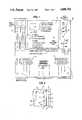
- FIG. 1is a front plan view of the controller of the present invention showing the logic unit as it appears when mounted on the NEMA enclosure backplate;
- FIG. 2is a partial representational side sectional view of the logic unit
- FIG. 3is a flow chart showing the relationship between the main components of the controller
- FIG. 4is a chart depicting the relationship between the various controller setpoints.
- FIG. 5is a representative dipswitch setting diagram for the controller.
- the controller of the present inventioncomprises a logic unit 10 housed in a completely enclosed six-side stainless steel casing 12.
- an Input/Output (I/O) board 14which is connected at 16 to a logic board 18 upon which is mounted a Z-80 microprocessor 20, an expansion bus 21 and an EPROM memory chip 23.
- the logic boardis isolated from the I/O board by means of a vertical metal plate 22. The metal plate isolates and shields the logic board from electrical noise and other interference, thereby ensuring protection of the microprocessor.
- the casing 12is specifically designed to protect the logic unit, not only from transient surges, but from the harsh environment typically found at remote sites, as well as the vibration associated with fuel consumable generator installations.
- the logic boardis cable connected at 24 to a display board 26.
- the circuitry for the display board, the logic board and the I/O boardis deemed to be conventional, being known to those skilled in the art, and is not considered to form part of the claimed invention.
- a terminal strip 28 for connection of input and output sensing wiresis provided on a portion of the I/O board which extends downwardly from the metal casing 12.
- a downwardly projecting metal lip 30is provided on the casing in order to protect the I/O board extension.
- This small extension of the I/O boardis the only portion of the logic unit which is not completely housed inside the casing 12.
- a solid state temperature sensor 31 and a plurality of relay drivers 33are provided on the I/O board.
- the logic unitis mounted on a metal back plate 32 disposed inside a larger NEMA metal equipment enclosure having a hinged door (not shown).
- the back platehas mounted thereon a main terminal block 36, a plurality of system relays 38, preferably of the mercury displacement type, and a series of shunts 40 calibrated for current measurement. Wiring from the various system components is connected at the main terminal block, from which the sensing wires are connected to the terminal strip 28 on the I/O board extension. In this manner, the heavy system wiring is isolated from the logic unit, which receives its input from the smaller sensing wires.
- the front surface of the logic unitis provided with a digital display meter 42, a display selector button 44 and a plurality of display LED's 46.
- logic unit casing 12is a weather-resistant, stainless steel casing which is capable of shielding against transient surges so as to protect the microprocessor from damage.
- the enclosure which receives backplate 32is a standard NEMA type equipment enclosure. Each of the enclosures is capable of withstanding severe environmental conditions, as well as the noise and vibration of generator installations.
- the controlleris designed to operate over a temperature range of -40° C. to 60° C. and a humidity range of 0 to 100% relative humidity. Operation of the controller can best be described in conjunction with the flow chart depicted in FIG. 3. The controller is powered by tapping off a 12 V block of the main system battery.
- This 2 V tap, or CONTROLLER INPUT,is regulated by the CONTROLLER POWER SUPPLY to approximately 5 V.
- This featureis considered to be unique over prior art devices, in that prior art controllers, which are characterized by a high parasitic load, derive their power from the entire battery bank.
- the power demands of a prior art discrete-type controllerare too great to allow a tap off a 12 V battery because the high draw would inevitably lead to battery undercharge.
- the present controlleris able to overcome the high power demands generally associated with prior art devices because of its relatively small parasitic load, generally only around 35 mA and because it incorporates circuitry, to be further discussed herein, which provides a "sleep" feature for the controller.
- the controller inputmeasures the battery voltage to obtain a reference so as to provide an analog reference voltage for calculations to be performed by the microprocessor.
- one of the shunts 40 mounted on back plate 32measures battery current for the system (BATTERY SHUNT INPUT), while the other of the shunts 40 measures the load current (LOAD SHUNT INPUT).
- BATTERY SHUNT INPUTbattery current for the system
- LOAD SHUNT INPUTload current
- the solid state TEMPERATURE SENSOR 31measures ambient temperature, the value for which is similarly converted to digital form and provided as input to the microprocessor.
- the foregoing inputsare provided to the Z-80 MICROPROCESSOR 20 mounted on the logic board.
- the microprocessoris utilized to perform all of the system calculations and controller operations.
- the microprocessoris utilized in conjunction with a non-volatile memory chip (EPROM MEMORY) 23 provided on the logic board, which contains the operational software or particular control algorithm which has been incorporated into the controller.
- EPROM MEMORYnon-volatile memory chip
- the particular control algorithm "burned into” the EPROMmay assume many forms, depending upon design requirements for the PV system and, hence, does not form part of the present invention. Indeed, the present controller contemplates replacement of the EPROM to adapt the controller to an entirely different set of operating functions.
- the program variablesare temporarily stored in random access memory (RAM MEMORY).
- a bank of DIP SWITCHES shown in FIG. 5, preferably thirty,are provided on the logic board and are adapted to be manually adjusted to select the various system setpoints from an available range of setpoints, which are utilized by the microprocessor as reference points in the control algorithm and which determine the various operational functions of the controller.
- the DIP switches and their associated setpointsare discussed hereafter in greater detail.
- the "sleep” feature that is a unique characteristic of the subject controlleris accomplished by means of miscellaneous TIMING/SUPPORT integrated circuits which are utilized in the overall operation of the microprocessor.
- the "sleep” featuremakes the 12 V tap providing power for the controller feasible by timing the circuitry to be turned off for a certain interval, from milliseconds to two seconds, followed by being turned on for a certain interval while the controller performs all of its monitoring and regulating functions generally for only a few milliseconds. By being turned off for most of the time, the controller's power requirements are greatly reduced, in contrast with prior art devices which are continually "on” and, hence, continually drawing power.
- RELAY DRIVERS 33which are provided on the I/O board are each adapted to actuate a respective EXTERNAL (MDR) MERCURY DISPLACEMENT RELAY 38 mounted on the back plate 32 in response to a signal from the microprocessor.
- MDREXTERNAL
- Each of the relays 38is adapted to perform a particular system function to be discussed further herein. Power for the relays 38 is provided by a RELAY POWER INPUT connection which supplies current for operating the external relays.
- the controllermay include a printed circuit board mounted INTERNAL DOUBLE POLE DOUBLE THROW (DPDT) RELAY and a printed circuit board mounted INTERNAL SINGLE POLE SINGLE THROW (SPST) RELAY which, in response to a signal from the microprocessor, are utilized to perform various control functions, such as starting an auxiliary generator by means of EXTERNAL GENERATOR START CIRCUITRY and actuating an external alarm by means of EXTERNAL ALARM CIRCUITRY.
- DPDTINTERNAL DOUBLE POLE DOUBLE THROW
- SPSTprinted circuit board mounted INTERNAL SINGLE POLE SINGLE THROW
- the EXPANSION BUS 21 located on the logic boardprovides a socket connection for optional FUTURE EXPANSION to another printed circuit board inside or outside the controller for additional inputs and outputs, or to a real time clock, etc.
- the expansion busalso serves to connect the microprocessor to the DISPLAY printed circuit board 26 containing a solid state meter, status LED's and display selector switch. Because the display is connected through the expansion bus, a display failure has no adverse effect on the controller.
- the display meteris adapted to remain off until such time as the selector button is manually depressed to visually display the desired system parameter.
- the appropriate status indicatoralthough normally on, is designed to blink so as to reduce power consumption.
- the controllerfurther includes an ANALOG BACKUP CONTROLLER utilizing analog circuitry which is adapted to assume basic control functions in the event of a microprocessor failure. The analog backup derives its power from the 12 V tap off the system battery previously described.
- the controller of the present inventionis powered through a 12 V tap off of the system battery and senses input data typically relating to battery system voltage, battery current and load current. These parameters are sensed by the controller by mean of a plurality of input sensing wires connected to the terminal strip 28 provided on the I/O board extension from the main terminal block on the backplate
- the system wiring from the PV array, the battery and the loadare connected to the main terminal block and do not go directly into the logic unit.
- the controller's microprocessorutilizes these inputs to perform a variety of monitoring and regulating functions in accordance with the control algorithm of the EPROM.
- the control algorithm or software that is "burned into” the EPROMwill vary according to the particular PV power system and its design and operational requirements.
- the design and operational requirements of the systemwill dictate the various functions which the controller is to perform, depending upon certain setpoints for the monitored variables in the system.
- the specific setpointsare "set", or communicated, to the microprocessor through a plurality of DIP switches.
- the relationship of the diverse setpoints to the control functionscan best be understood in conjunction with the chart set forth in FIG. 4.
- the functions of the photovoltaic system controllertypically involve PV array regulation, load management, auxiliary generator control, monitoring of system parameters and alarm functions.
- PV array regulationis necessary in order to protect the battery from overcharge due to mismatch between the available solar radiation and the specific load profile.
- the subject controlleris adapted to ensure that the battery receives the maximum possible amount of charge while preventing overcharge and excess gassing.
- the system voltage and battery current which are provided as digital input signals to the microprocessorare temperature compensated and evaluated according to the control algorithm with respect to a predetermined system voltage, called the ARRAY DISCONNECT setpoint.
- the Array Disconnect setpointgenerally corresponds to an 85-95% battery state of charge, depending upon the exact charging current.
- Charge regulationis initiated when the actual system voltage determined by the microprocessor reaches the Array Disconnect setpoint.
- the microprocessorthen signals the appropriate relay driver to open the external array disconnect mercury displacement relay, thereby disconnecting the array from the battery. Actuation of the relay causes the system voltage to fall as the battery switches from charge mode to open circuit or discharge mode.
- the controllerdetermines that the battery voltage has reached a second lower level, called the Array Reconnect setpoint, the controller signals the appropriate relay to reconnect the array, resuming charging.
- Load management functions performed by the controllerconsist of preventing battery undercharge, and possible polarity reversal, by actuating a low voltage alarm followed by disconnection of the load if the system voltage continues to fall.
- the system voltageis determined by the microprocessor based upon the microprocessor input and analyzed according to the control algorithm with respect to a Low Alarm setpoint. If the system voltage reaches the Low Alarm setpoint, the microprocessor causes the "UNDER VOLTAGE" and "ALARM" LED's on the display panel of the logic unit to light.
- the internal SPST relayis capable of sending a signal through alarm circuitry for activating an external alarm.
- the microprocessorwill cause the appropriate relay driver to open the load disconnect mercury displacement relay to disconnect the load form the battery.
- the timing integrated circuit provided on the logic boardserves to prevent nuisance disconnects of the load by creating a built-in time delay.
- the system voltagemust remain below the load disconnect threshold for approximately three minutes before the controller actually causes the relay to be opened. During this time, the red "LOAD DISCONNECT" LED will flash, but the load will remain connected. Once the load has been disconnected, it remains disconnected until the microprocessor determines that the system voltage has risen to the Load Reconnect setpoint.
- the controllerprovides for auxiliary generator control in a PV hybrid power system by means of the internal DPDT relay, which controls starting and stopping of a Thermo Electric Generator (TEG) or Diesel Electric Generator (DEG).
- TEGThermo Electric Generator
- DEGDiesel Electric Generator
- the microprocessoris adapted to effect actuation of an auxiliary generator upon its determining that the battery voltage has fallen to a setpoint known as the GEN START setpoint, corresponding to between 20% and 70% state of charge, depending upon the type and specification of the power system. Once the generator has been turned on, it remains on until the battery reaches the GEN STOP setpoint.
- the controlleris capable of indicating system status through the series of LED's 46 on the front cover of the logic unit 10. During normal charging or discharging of the battery, a green “NORMAL” LED will be flashing. The "NORMAL” indicator is replaced by other blinking LED's depending on the actual system status, e.g. "LOAD DISCONNECT” "ARRAY DISCONNECT”, “ALARM”, “GENERATOR START”, “OVERVOLTAGE” and “UNDERVOLTAGE”.
- the controlleris specifically adapted to display system voltage, battery, load and array currents, as well as ambient temperature on display meter 42.
- the displayis activated by manually pressing the display button 44 and holding it down until the display appears.
- Each of the valuescan be read by depressing the button until the respective LED's light to show that the desired value is being displayed.
- the controllerthus conserves battery power by maintaining the display in a generally unlighted or "off" mode until such time as the display button is depressed.
- the LED's that are normally on to indicate system statusare adapted to blink in order to reduce power requirements.
- the displaywill remain on for only about 90 seconds after the button is pushed, then automatically turns itself off in a further effort to conserve battery power.
- a salient feature of the subject inventionpertains to the controller's ability to accommodate a wide range of operating parameters.
- all of the predetermined setpoints hereinbefore discussed, which dictate when and what the controller does,are easily field adjustable to conform to diverse system requirements.
- the adjustmentis achieved by means of a bank of DIP switches, preferably thirty, as shown in FIG. 5. These DIP switches are adapted to be manually adjusted in the field to reset the High Voltage Alarm setpoint, the Array Disconnect setpoint, the Generator Stop setpoint, the Array Reconnect setpoint, the Load Reconnect setpoint, the Generator Start setpoint, the Low Voltage Alarm setpoint and the Low Voltage Load Disconnect setpoint.
- the settingsare adjusted by establishing a reference diagram wherein the various possible combinations of DIP switch settings correspond to the various setpoint values.
- An additional salient feature of the controllerrelates to replacement of the EPROM.
- the microprocessor controlleris adapted to be reprogrammed by replacing the program memory chip in the logic board with a new EPROM containing a different set of instructions.
- the EPROMis supplied in a Zero Insertion Force Socket to facilitate replacement.
Landscapes
- Engineering & Computer Science (AREA)
- Power Engineering (AREA)
- Charge And Discharge Circuits For Batteries Or The Like (AREA)
Abstract
Description
Claims (19)
Priority Applications (1)
| Application Number | Priority Date | Filing Date | Title |
|---|---|---|---|
| US07/087,314US4888702A (en) | 1987-08-20 | 1987-08-20 | Photovoltaic system controller |
Applications Claiming Priority (1)
| Application Number | Priority Date | Filing Date | Title |
|---|---|---|---|
| US07/087,314US4888702A (en) | 1987-08-20 | 1987-08-20 | Photovoltaic system controller |
Publications (1)
| Publication Number | Publication Date |
|---|---|
| US4888702Atrue US4888702A (en) | 1989-12-19 |
Family
ID=22204429
Family Applications (1)
| Application Number | Title | Priority Date | Filing Date |
|---|---|---|---|
| US07/087,314Expired - LifetimeUS4888702A (en) | 1987-08-20 | 1987-08-20 | Photovoltaic system controller |
Country Status (1)
| Country | Link |
|---|---|
| US (1) | US4888702A (en) |
Cited By (93)
| Publication number | Priority date | Publication date | Assignee | Title |
|---|---|---|---|---|
| US5150034A (en)* | 1989-10-25 | 1992-09-22 | Fuji Jukogyo Kabushiki Kaisha | Automatically charging system for electric automobile |
| US5159259A (en)* | 1991-07-15 | 1992-10-27 | American Signal Company | Power supply system for continuously energizing a D.C. load |
| EP0460453A3 (en)* | 1990-06-02 | 1992-12-16 | Schottel-Werft Josef Becker Gmbh & Co Kg. | Power production installation, especially propeller propulsion for ships using a solar generator |
| US5235266A (en)* | 1990-06-02 | 1993-08-10 | Schottel-Werft Josef Becker Gmbh & Co. Kg | Energy-generating plant, particularly propeller-type ship's propulsion plant, including a solar generator |
| US5438225A (en)* | 1992-02-06 | 1995-08-01 | Murphy Management Inc. | Solar powered annuciator |
| US5563456A (en)* | 1992-02-06 | 1996-10-08 | Murphy Management Inc. | Solar powered annunciator |
| US5608306A (en)* | 1994-03-15 | 1997-03-04 | Ericsson Inc. | Rechargeable battery pack with identification circuit, real time clock and authentication capability |
| WO2000000839A1 (en)* | 1998-06-26 | 2000-01-06 | Fraunhofer-Gesellschaft zur Förderung der angewandten Forschung e.V. | Device for testing solar home systems |
| US6049190A (en)* | 1998-04-13 | 2000-04-11 | Space Systems/Loral, Inc. | Spacecraft power system |
| US6433522B1 (en)* | 2001-05-02 | 2002-08-13 | The Aerospace Corporation | Fault tolerant maximum power tracking solar power system |
| EP1024575A3 (en)* | 1999-01-28 | 2002-11-27 | Canon Kabushiki Kaisha | Photovoltaic power generation apparatus and control method thereof |
| US20030112123A1 (en)* | 2001-12-19 | 2003-06-19 | Hom Wayne C. | Method and apparatus for providing a programmable gate security system |
| US6624609B2 (en) | 2000-12-13 | 2003-09-23 | Leonard G. D. Allen | Solar powered monitor |
| US20040199476A1 (en)* | 2001-03-22 | 2004-10-07 | Fernando Milanes Garcia-Moreno | Electronic and mechanical system for automated or discretionay dosage of potable water at the particular intake level of each user |
| US20040199477A1 (en)* | 2001-03-22 | 2004-10-07 | Fernando Milanes Garcia-Moreno | Electronic method and system for instant creation and storage of consumption histograms in drinkable water tapping points |
| ES2221559A1 (en)* | 2003-03-24 | 2004-12-16 | Universidad De Jaen | Expert controller for independent photovoltaic system, has communication module allowing to contact control element with remote user relative to state of installation, instantaneous values, temporary evolution, remote events and alarms |
| US20060171182A1 (en)* | 2005-01-28 | 2006-08-03 | Kasemsan Siri | Solar array inverter with maximum power tracking |
| US7154253B1 (en)* | 2003-07-03 | 2006-12-26 | Inovys Corporation | Digitally controlled modular power supply for automated test equipment |
| US20080067227A1 (en)* | 2003-06-09 | 2008-03-20 | Poss James A | Eletrically-powered programmable package deposit enclosure |
| US20080111517A1 (en)* | 2006-11-15 | 2008-05-15 | Pfeifer John E | Charge Controller for DC-DC Power Conversion |
| US20090039852A1 (en)* | 2007-08-06 | 2009-02-12 | Solaredge Technologies Ltd. | Digital average input current control in power converter |
| US20090145480A1 (en)* | 2007-12-05 | 2009-06-11 | Meir Adest | Photovoltaic system power tracking method |
| US20090146667A1 (en)* | 2007-12-05 | 2009-06-11 | Meir Adest | Testing of a photovoltaic panel |
| US20090179662A1 (en)* | 2008-01-10 | 2009-07-16 | Moulton Thomas A | System for Monitoring Individual Photovoltaic Modules |
| US20090206666A1 (en)* | 2007-12-04 | 2009-08-20 | Guy Sella | Distributed power harvesting systems using dc power sources |
| US20090273481A1 (en)* | 2008-01-15 | 2009-11-05 | John Traywick | Solar-Charged Power Source |
| US20100071274A1 (en)* | 2008-09-23 | 2010-03-25 | Joe Brescia | Unitized Curtain Wall Module Adapted for Integrated Photovoltaic Conversion Module |
| ES2335838A1 (en)* | 2007-06-20 | 2010-04-05 | Juan Carlos Benito De Blas | SYSTEM OF MONITORING AND TELECONTROL OF ENERGY GENERATORS INTEGRATED BY PHOTOVOLTAIC EFFECT PANELS. |
| US20100126087A1 (en)* | 2008-11-13 | 2010-05-27 | Joe Brescia | Plank Based Photovoltaic Conversion System |
| US20100301991A1 (en)* | 2009-05-26 | 2010-12-02 | Guy Sella | Theft detection and prevention in a power generation system |
| US20110037600A1 (en)* | 2009-08-17 | 2011-02-17 | Toru Takehara | Photovoltaic panel monitoring apparatus |
| US20110084553A1 (en)* | 2007-12-04 | 2011-04-14 | Meir Adest | Distributed power system using direct current power sources |
| US20110121652A1 (en)* | 2006-12-06 | 2011-05-26 | Guy Sella | Pairing of components in a direct current distributed power generation system |
| US20110125431A1 (en)* | 2007-12-05 | 2011-05-26 | Meir Adest | Testing of a Photovoltaic Panel |
| US20110133552A1 (en)* | 2009-12-01 | 2011-06-09 | Yaron Binder | Dual Use Photovoltaic System |
| US20110161722A1 (en)* | 2009-12-29 | 2011-06-30 | Tigo Energy | Systems and Methods for a Communication Protocol Between a Local Controller and a Master Controller |
| US20110173276A1 (en)* | 2010-01-08 | 2011-07-14 | Tigo Energy | Systems and Methods for an Identification Protocol Between a Local Controller and a Master Controller |
| US20110181340A1 (en)* | 2010-01-27 | 2011-07-28 | Meir Gazit | Fast Voltage Level Shifter Circuit |
| CN102157966A (en)* | 2011-04-12 | 2011-08-17 | 江西日普升太阳能光伏产业有限公司 | Intelligent photovoltaic controller with multiple functions |
| US20110260866A1 (en)* | 2010-04-22 | 2011-10-27 | Tigo Energy | Enhanced System and Method for Theft Prevention in a Solar Power Array During Nonoperative Periods |
| US20120197449A1 (en)* | 2011-01-28 | 2012-08-02 | Dean Sanders | Systems, apparatus, and methods of a solar energy grid integrated system with energy storage appliance |
| US8289742B2 (en) | 2007-12-05 | 2012-10-16 | Solaredge Ltd. | Parallel connected inverters |
| US8319471B2 (en) | 2006-12-06 | 2012-11-27 | Solaredge, Ltd. | Battery power delivery module |
| US8384243B2 (en) | 2007-12-04 | 2013-02-26 | Solaredge Technologies Ltd. | Distributed power harvesting systems using DC power sources |
| US8473250B2 (en) | 2006-12-06 | 2013-06-25 | Solaredge, Ltd. | Monitoring of distributed power harvesting systems using DC power sources |
| US8531055B2 (en) | 2006-12-06 | 2013-09-10 | Solaredge Ltd. | Safety mechanisms, wake up and shutdown methods in distributed power installations |
| US8570005B2 (en) | 2011-09-12 | 2013-10-29 | Solaredge Technologies Ltd. | Direct current link circuit |
| US8587151B2 (en) | 2006-12-06 | 2013-11-19 | Solaredge, Ltd. | Method for distributed power harvesting using DC power sources |
| US20130314236A1 (en)* | 2012-05-11 | 2013-11-28 | Area Energy Limited | Photovoltaic arrays |
| US8816535B2 (en) | 2007-10-10 | 2014-08-26 | Solaredge Technologies, Ltd. | System and method for protection during inverter shutdown in distributed power installations |
| US8957645B2 (en) | 2008-03-24 | 2015-02-17 | Solaredge Technologies Ltd. | Zero voltage switching |
| US8988838B2 (en) | 2012-01-30 | 2015-03-24 | Solaredge Technologies Ltd. | Photovoltaic panel circuitry |
| US9000617B2 (en) | 2008-05-05 | 2015-04-07 | Solaredge Technologies, Ltd. | Direct current power combiner |
| US9006569B2 (en) | 2009-05-22 | 2015-04-14 | Solaredge Technologies Ltd. | Electrically isolated heat dissipating junction box |
| US9088178B2 (en) | 2006-12-06 | 2015-07-21 | Solaredge Technologies Ltd | Distributed power harvesting systems using DC power sources |
| US9130401B2 (en) | 2006-12-06 | 2015-09-08 | Solaredge Technologies Ltd. | Distributed power harvesting systems using DC power sources |
| US9235228B2 (en) | 2012-03-05 | 2016-01-12 | Solaredge Technologies Ltd. | Direct current link circuit |
| US9318974B2 (en) | 2014-03-26 | 2016-04-19 | Solaredge Technologies Ltd. | Multi-level inverter with flying capacitor topology |
| US9401599B2 (en) | 2010-12-09 | 2016-07-26 | Solaredge Technologies Ltd. | Disconnection of a string carrying direct current power |
| US9548619B2 (en) | 2013-03-14 | 2017-01-17 | Solaredge Technologies Ltd. | Method and apparatus for storing and depleting energy |
| US9647442B2 (en) | 2010-11-09 | 2017-05-09 | Solaredge Technologies Ltd. | Arc detection and prevention in a power generation system |
| US9812984B2 (en) | 2012-01-30 | 2017-11-07 | Solaredge Technologies Ltd. | Maximizing power in a photovoltaic distributed power system |
| US9819178B2 (en) | 2013-03-15 | 2017-11-14 | Solaredge Technologies Ltd. | Bypass mechanism |
| US9831824B2 (en) | 2007-12-05 | 2017-11-28 | SolareEdge Technologies Ltd. | Current sensing on a MOSFET |
| US9853565B2 (en) | 2012-01-30 | 2017-12-26 | Solaredge Technologies Ltd. | Maximized power in a photovoltaic distributed power system |
| US9866098B2 (en) | 2011-01-12 | 2018-01-09 | Solaredge Technologies Ltd. | Serially connected inverters |
| US9870016B2 (en) | 2012-05-25 | 2018-01-16 | Solaredge Technologies Ltd. | Circuit for interconnected direct current power sources |
| US9941813B2 (en) | 2013-03-14 | 2018-04-10 | Solaredge Technologies Ltd. | High frequency multi-level inverter |
| US9966487B2 (en) | 2015-12-14 | 2018-05-08 | Solarcity Corporation | Strain relief apparatus for solar modules |
| US10061957B2 (en) | 2016-03-03 | 2018-08-28 | Solaredge Technologies Ltd. | Methods for mapping power generation installations |
| US10115841B2 (en) | 2012-06-04 | 2018-10-30 | Solaredge Technologies Ltd. | Integrated photovoltaic panel circuitry |
| US10230310B2 (en) | 2016-04-05 | 2019-03-12 | Solaredge Technologies Ltd | Safety switch for photovoltaic systems |
| US20190113014A1 (en)* | 2016-04-01 | 2019-04-18 | Aldelano Ip Holdings, Llc | Automatic generator start system for a portable generator having electric start |
| US10473507B2 (en)* | 2016-04-28 | 2019-11-12 | Fluid Handling Llc | E-11 switch assembly |
| US10599113B2 (en) | 2016-03-03 | 2020-03-24 | Solaredge Technologies Ltd. | Apparatus and method for determining an order of power devices in power generation systems |
| US10673229B2 (en) | 2010-11-09 | 2020-06-02 | Solaredge Technologies Ltd. | Arc detection and prevention in a power generation system |
| US10673222B2 (en) | 2010-11-09 | 2020-06-02 | Solaredge Technologies Ltd. | Arc detection and prevention in a power generation system |
| US10931119B2 (en) | 2012-01-11 | 2021-02-23 | Solaredge Technologies Ltd. | Photovoltaic module |
| US11018623B2 (en) | 2016-04-05 | 2021-05-25 | Solaredge Technologies Ltd. | Safety switch for photovoltaic systems |
| US11081608B2 (en) | 2016-03-03 | 2021-08-03 | Solaredge Technologies Ltd. | Apparatus and method for determining an order of power devices in power generation systems |
| US11177663B2 (en) | 2016-04-05 | 2021-11-16 | Solaredge Technologies Ltd. | Chain of power devices |
| US11264947B2 (en) | 2007-12-05 | 2022-03-01 | Solaredge Technologies Ltd. | Testing of a photovoltaic panel |
| US11296650B2 (en) | 2006-12-06 | 2022-04-05 | Solaredge Technologies Ltd. | System and method for protection during inverter shutdown in distributed power installations |
| US11309832B2 (en) | 2006-12-06 | 2022-04-19 | Solaredge Technologies Ltd. | Distributed power harvesting systems using DC power sources |
| US11569659B2 (en) | 2006-12-06 | 2023-01-31 | Solaredge Technologies Ltd. | Distributed power harvesting systems using DC power sources |
| US11687112B2 (en) | 2006-12-06 | 2023-06-27 | Solaredge Technologies Ltd. | Distributed power harvesting systems using DC power sources |
| US11728768B2 (en) | 2006-12-06 | 2023-08-15 | Solaredge Technologies Ltd. | Pairing of components in a direct current distributed power generation system |
| US11735910B2 (en) | 2006-12-06 | 2023-08-22 | Solaredge Technologies Ltd. | Distributed power system using direct current power sources |
| US11855231B2 (en) | 2006-12-06 | 2023-12-26 | Solaredge Technologies Ltd. | Distributed power harvesting systems using DC power sources |
| US11881814B2 (en) | 2005-12-05 | 2024-01-23 | Solaredge Technologies Ltd. | Testing of a photovoltaic panel |
| US11888387B2 (en) | 2006-12-06 | 2024-01-30 | Solaredge Technologies Ltd. | Safety mechanisms, wake up and shutdown methods in distributed power installations |
| US12057807B2 (en) | 2016-04-05 | 2024-08-06 | Solaredge Technologies Ltd. | Chain of power devices |
| US12418177B2 (en) | 2009-10-24 | 2025-09-16 | Solaredge Technologies Ltd. | Distributed power system using direct current power sources |
Citations (8)
| Publication number | Priority date | Publication date | Assignee | Title |
|---|---|---|---|---|
| US3863270A (en)* | 1972-05-19 | 1975-01-28 | Paul H Haley | Hybrid computer system including an analog calculator for rapidly generating electric power system loadflow solutions |
| US4327318A (en)* | 1980-10-31 | 1982-04-27 | Exxon Research & Engineering Co. | Source shedding regulator |
| US4390940A (en)* | 1980-06-26 | 1983-06-28 | Societe Nationale Industrielle Aerospatiale | Process and system for producing photovoltaic power |
| US4455614A (en)* | 1973-09-21 | 1984-06-19 | Westinghouse Electric Corp. | Gas turbine and steam turbine combined cycle electric power generating plant having a coordinated and hybridized control system and an improved factory based method for making and testing combined cycle and other power plants and control systems therefor |
| US4551980A (en)* | 1983-03-25 | 1985-11-12 | Ormat Turbines, Ltd. | Hybrid system for generating power |
| US4633418A (en)* | 1984-07-11 | 1986-12-30 | The United States Of America As Represented By The Secretary Of The Air Force | Battery control and fault detection method |
| US4681515A (en)* | 1985-02-25 | 1987-07-21 | Allen James C | Walking beam pump having adjustable crank pin |
| US4689544A (en)* | 1985-10-17 | 1987-08-25 | Hughes Aircraft Company | Control of the charging of pressurized gas-metal electrical storage cells |
- 1987
- 1987-08-20USUS07/087,314patent/US4888702A/ennot_activeExpired - Lifetime
Patent Citations (8)
| Publication number | Priority date | Publication date | Assignee | Title |
|---|---|---|---|---|
| US3863270A (en)* | 1972-05-19 | 1975-01-28 | Paul H Haley | Hybrid computer system including an analog calculator for rapidly generating electric power system loadflow solutions |
| US4455614A (en)* | 1973-09-21 | 1984-06-19 | Westinghouse Electric Corp. | Gas turbine and steam turbine combined cycle electric power generating plant having a coordinated and hybridized control system and an improved factory based method for making and testing combined cycle and other power plants and control systems therefor |
| US4390940A (en)* | 1980-06-26 | 1983-06-28 | Societe Nationale Industrielle Aerospatiale | Process and system for producing photovoltaic power |
| US4327318A (en)* | 1980-10-31 | 1982-04-27 | Exxon Research & Engineering Co. | Source shedding regulator |
| US4551980A (en)* | 1983-03-25 | 1985-11-12 | Ormat Turbines, Ltd. | Hybrid system for generating power |
| US4633418A (en)* | 1984-07-11 | 1986-12-30 | The United States Of America As Represented By The Secretary Of The Air Force | Battery control and fault detection method |
| US4681515A (en)* | 1985-02-25 | 1987-07-21 | Allen James C | Walking beam pump having adjustable crank pin |
| US4689544A (en)* | 1985-10-17 | 1987-08-25 | Hughes Aircraft Company | Control of the charging of pressurized gas-metal electrical storage cells |
Non-Patent Citations (2)
| Title |
|---|
| Chetty et al, "Microprocessor-Controlled Digital Shunt Regulator", IEEE Transactions on Aerospace and Electronic Systems, vol. AES-16, No. 2, Mar. 1980. |
| Chetty et al, Microprocessor Controlled Digital Shunt Regulator , IEEE Transactions on Aerospace and Electronic Systems, vol. AES 16, No. 2, Mar. 1980.* |
Cited By (288)
| Publication number | Priority date | Publication date | Assignee | Title |
|---|---|---|---|---|
| US5150034A (en)* | 1989-10-25 | 1992-09-22 | Fuji Jukogyo Kabushiki Kaisha | Automatically charging system for electric automobile |
| EP0460453A3 (en)* | 1990-06-02 | 1992-12-16 | Schottel-Werft Josef Becker Gmbh & Co Kg. | Power production installation, especially propeller propulsion for ships using a solar generator |
| US5235266A (en)* | 1990-06-02 | 1993-08-10 | Schottel-Werft Josef Becker Gmbh & Co. Kg | Energy-generating plant, particularly propeller-type ship's propulsion plant, including a solar generator |
| US5159259A (en)* | 1991-07-15 | 1992-10-27 | American Signal Company | Power supply system for continuously energizing a D.C. load |
| US5438225A (en)* | 1992-02-06 | 1995-08-01 | Murphy Management Inc. | Solar powered annuciator |
| US5563456A (en)* | 1992-02-06 | 1996-10-08 | Murphy Management Inc. | Solar powered annunciator |
| US5608306A (en)* | 1994-03-15 | 1997-03-04 | Ericsson Inc. | Rechargeable battery pack with identification circuit, real time clock and authentication capability |
| US6049190A (en)* | 1998-04-13 | 2000-04-11 | Space Systems/Loral, Inc. | Spacecraft power system |
| WO2000000839A1 (en)* | 1998-06-26 | 2000-01-06 | Fraunhofer-Gesellschaft zur Förderung der angewandten Forschung e.V. | Device for testing solar home systems |
| EP1024575A3 (en)* | 1999-01-28 | 2002-11-27 | Canon Kabushiki Kaisha | Photovoltaic power generation apparatus and control method thereof |
| US6624609B2 (en) | 2000-12-13 | 2003-09-23 | Leonard G. D. Allen | Solar powered monitor |
| US20040199476A1 (en)* | 2001-03-22 | 2004-10-07 | Fernando Milanes Garcia-Moreno | Electronic and mechanical system for automated or discretionay dosage of potable water at the particular intake level of each user |
| US20040199477A1 (en)* | 2001-03-22 | 2004-10-07 | Fernando Milanes Garcia-Moreno | Electronic method and system for instant creation and storage of consumption histograms in drinkable water tapping points |
| US8423302B2 (en)* | 2001-03-22 | 2013-04-16 | Fernando Milanes Garcia-Moreno | Electronic method and system for instant creation and storage of consumption histograms in drinkable water tapping points |
| US8719187B2 (en)* | 2001-03-22 | 2014-05-06 | Fernando Milanes Garcia-Moreno | Electronic and mechanical system for automated or discretionay dosage of potable water at the particular intake level of each user |
| US6433522B1 (en)* | 2001-05-02 | 2002-08-13 | The Aerospace Corporation | Fault tolerant maximum power tracking solar power system |
| US20030112123A1 (en)* | 2001-12-19 | 2003-06-19 | Hom Wayne C. | Method and apparatus for providing a programmable gate security system |
| ES2221559A1 (en)* | 2003-03-24 | 2004-12-16 | Universidad De Jaen | Expert controller for independent photovoltaic system, has communication module allowing to contact control element with remote user relative to state of installation, instantaneous values, temporary evolution, remote events and alarms |
| ES2221559B1 (en)* | 2003-03-24 | 2006-02-16 | Universidad De Jaen | "EXPERT CONTROLLER OF AUTONOMOUS PHOTOVOLTAIC SYSTEMS". |
| US20080067227A1 (en)* | 2003-06-09 | 2008-03-20 | Poss James A | Eletrically-powered programmable package deposit enclosure |
| US7154253B1 (en)* | 2003-07-03 | 2006-12-26 | Inovys Corporation | Digitally controlled modular power supply for automated test equipment |
| US7193872B2 (en) | 2005-01-28 | 2007-03-20 | Kasemsan Siri | Solar array inverter with maximum power tracking |
| US7324361B2 (en) | 2005-01-28 | 2008-01-29 | Kasemsan Siri | Solar array inverter with maximum power tracking |
| US20070159866A1 (en)* | 2005-01-28 | 2007-07-12 | Kasemsan Siri | Solar array inverter with maximum power tracking |
| US20060171182A1 (en)* | 2005-01-28 | 2006-08-03 | Kasemsan Siri | Solar array inverter with maximum power tracking |
| US11881814B2 (en) | 2005-12-05 | 2024-01-23 | Solaredge Technologies Ltd. | Testing of a photovoltaic panel |
| US20080111517A1 (en)* | 2006-11-15 | 2008-05-15 | Pfeifer John E | Charge Controller for DC-DC Power Conversion |
| US11594882B2 (en) | 2006-12-06 | 2023-02-28 | Solaredge Technologies Ltd. | Distributed power harvesting systems using DC power sources |
| US11063440B2 (en) | 2006-12-06 | 2021-07-13 | Solaredge Technologies Ltd. | Method for distributed power harvesting using DC power sources |
| US12276997B2 (en) | 2006-12-06 | 2025-04-15 | Solaredge Technologies Ltd. | Distributed power harvesting systems using DC power sources |
| US12224706B2 (en) | 2006-12-06 | 2025-02-11 | Solaredge Technologies Ltd. | Pairing of components in a direct current distributed power generation system |
| US12107417B2 (en) | 2006-12-06 | 2024-10-01 | Solaredge Technologies Ltd. | Distributed power harvesting systems using DC power sources |
| US12068599B2 (en) | 2006-12-06 | 2024-08-20 | Solaredge Technologies Ltd. | System and method for protection during inverter shutdown in distributed power installations |
| US12046940B2 (en) | 2006-12-06 | 2024-07-23 | Solaredge Technologies Ltd. | Battery power control |
| US12032080B2 (en) | 2006-12-06 | 2024-07-09 | Solaredge Technologies Ltd. | Safety mechanisms, wake up and shutdown methods in distributed power installations |
| US12027970B2 (en) | 2006-12-06 | 2024-07-02 | Solaredge Technologies Ltd. | Safety mechanisms, wake up and shutdown methods in distributed power installations |
| US12027849B2 (en) | 2006-12-06 | 2024-07-02 | Solaredge Technologies Ltd. | Distributed power system using direct current power sources |
| US11961922B2 (en) | 2006-12-06 | 2024-04-16 | Solaredge Technologies Ltd. | Distributed power harvesting systems using DC power sources |
| US11962243B2 (en) | 2006-12-06 | 2024-04-16 | Solaredge Technologies Ltd. | Method for distributed power harvesting using DC power sources |
| US11888387B2 (en) | 2006-12-06 | 2024-01-30 | Solaredge Technologies Ltd. | Safety mechanisms, wake up and shutdown methods in distributed power installations |
| US12281919B2 (en) | 2006-12-06 | 2025-04-22 | Solaredge Technologies Ltd. | Monitoring of distributed power harvesting systems using DC power sources |
| US11855231B2 (en) | 2006-12-06 | 2023-12-26 | Solaredge Technologies Ltd. | Distributed power harvesting systems using DC power sources |
| US9368964B2 (en) | 2006-12-06 | 2016-06-14 | Solaredge Technologies Ltd. | Distributed power system using direct current power sources |
| US11735910B2 (en) | 2006-12-06 | 2023-08-22 | Solaredge Technologies Ltd. | Distributed power system using direct current power sources |
| US11728768B2 (en) | 2006-12-06 | 2023-08-15 | Solaredge Technologies Ltd. | Pairing of components in a direct current distributed power generation system |
| US11687112B2 (en) | 2006-12-06 | 2023-06-27 | Solaredge Technologies Ltd. | Distributed power harvesting systems using DC power sources |
| US11682918B2 (en) | 2006-12-06 | 2023-06-20 | Solaredge Technologies Ltd. | Battery power delivery module |
| US11658482B2 (en) | 2006-12-06 | 2023-05-23 | Solaredge Technologies Ltd. | Distributed power harvesting systems using DC power sources |
| US11598652B2 (en) | 2006-12-06 | 2023-03-07 | Solaredge Technologies Ltd. | Monitoring of distributed power harvesting systems using DC power sources |
| US9112379B2 (en) | 2006-12-06 | 2015-08-18 | Solaredge Technologies Ltd. | Pairing of components in a direct current distributed power generation system |
| US11594881B2 (en) | 2006-12-06 | 2023-02-28 | Solaredge Technologies Ltd. | Distributed power harvesting systems using DC power sources |
| US11594880B2 (en) | 2006-12-06 | 2023-02-28 | Solaredge Technologies Ltd. | Distributed power harvesting systems using DC power sources |
| US9088178B2 (en) | 2006-12-06 | 2015-07-21 | Solaredge Technologies Ltd | Distributed power harvesting systems using DC power sources |
| US9130401B2 (en) | 2006-12-06 | 2015-09-08 | Solaredge Technologies Ltd. | Distributed power harvesting systems using DC power sources |
| US11579235B2 (en) | 2006-12-06 | 2023-02-14 | Solaredge Technologies Ltd. | Safety mechanisms, wake up and shutdown methods in distributed power installations |
| US9041339B2 (en) | 2006-12-06 | 2015-05-26 | Solaredge Technologies Ltd. | Battery power delivery module |
| US20110121652A1 (en)* | 2006-12-06 | 2011-05-26 | Guy Sella | Pairing of components in a direct current distributed power generation system |
| US11575260B2 (en) | 2006-12-06 | 2023-02-07 | Solaredge Technologies Ltd. | Distributed power harvesting systems using DC power sources |
| US11575261B2 (en) | 2006-12-06 | 2023-02-07 | Solaredge Technologies Ltd. | Distributed power harvesting systems using DC power sources |
| US11569660B2 (en) | 2006-12-06 | 2023-01-31 | Solaredge Technologies Ltd. | Distributed power harvesting systems using DC power sources |
| US11569659B2 (en) | 2006-12-06 | 2023-01-31 | Solaredge Technologies Ltd. | Distributed power harvesting systems using DC power sources |
| US11476799B2 (en) | 2006-12-06 | 2022-10-18 | Solaredge Technologies Ltd. | Distributed power harvesting systems using DC power sources |
| US11309832B2 (en) | 2006-12-06 | 2022-04-19 | Solaredge Technologies Ltd. | Distributed power harvesting systems using DC power sources |
| US11296650B2 (en) | 2006-12-06 | 2022-04-05 | Solaredge Technologies Ltd. | System and method for protection during inverter shutdown in distributed power installations |
| US11183922B2 (en) | 2006-12-06 | 2021-11-23 | Solaredge Technologies Ltd. | Distributed power harvesting systems using DC power sources |
| US11073543B2 (en) | 2006-12-06 | 2021-07-27 | Solaredge Technologies Ltd. | Monitoring of distributed power harvesting systems using DC power sources |
| US9543889B2 (en) | 2006-12-06 | 2017-01-10 | Solaredge Technologies Ltd. | Distributed power harvesting systems using DC power sources |
| US11043820B2 (en) | 2006-12-06 | 2021-06-22 | Solaredge Technologies Ltd. | Battery power delivery module |
| US11031861B2 (en) | 2006-12-06 | 2021-06-08 | Solaredge Technologies Ltd. | System and method for protection during inverter shutdown in distributed power installations |
| US11002774B2 (en) | 2006-12-06 | 2021-05-11 | Solaredge Technologies Ltd. | Monitoring of distributed power harvesting systems using DC power sources |
| US8319471B2 (en) | 2006-12-06 | 2012-11-27 | Solaredge, Ltd. | Battery power delivery module |
| US9590526B2 (en) | 2006-12-06 | 2017-03-07 | Solaredge Technologies Ltd. | Safety mechanisms, wake up and shutdown methods in distributed power installations |
| US12316274B2 (en) | 2006-12-06 | 2025-05-27 | Solaredge Technologies Ltd. | Pairing of components in a direct current distributed power generation system |
| US10673253B2 (en) | 2006-12-06 | 2020-06-02 | Solaredge Technologies Ltd. | Battery power delivery module |
| US10637393B2 (en) | 2006-12-06 | 2020-04-28 | Solaredge Technologies Ltd. | Distributed power harvesting systems using DC power sources |
| US9644993B2 (en) | 2006-12-06 | 2017-05-09 | Solaredge Technologies Ltd. | Monitoring of distributed power harvesting systems using DC power sources |
| US9680304B2 (en) | 2006-12-06 | 2017-06-13 | Solaredge Technologies Ltd. | Method for distributed power harvesting using DC power sources |
| US12388492B2 (en) | 2006-12-06 | 2025-08-12 | Solaredge Technologies Ltd. | Safety mechanisms, wake up and shutdown methods in distributed power installations |
| US10447150B2 (en) | 2006-12-06 | 2019-10-15 | Solaredge Technologies Ltd. | Distributed power harvesting systems using DC power sources |
| US8473250B2 (en) | 2006-12-06 | 2013-06-25 | Solaredge, Ltd. | Monitoring of distributed power harvesting systems using DC power sources |
| US8531055B2 (en) | 2006-12-06 | 2013-09-10 | Solaredge Ltd. | Safety mechanisms, wake up and shutdown methods in distributed power installations |
| US10230245B2 (en) | 2006-12-06 | 2019-03-12 | Solaredge Technologies Ltd | Battery power delivery module |
| US8587151B2 (en) | 2006-12-06 | 2013-11-19 | Solaredge, Ltd. | Method for distributed power harvesting using DC power sources |
| US9853490B2 (en) | 2006-12-06 | 2017-12-26 | Solaredge Technologies Ltd. | Distributed power system using direct current power sources |
| US10097007B2 (en) | 2006-12-06 | 2018-10-09 | Solaredge Technologies Ltd. | Method for distributed power harvesting using DC power sources |
| US9966766B2 (en) | 2006-12-06 | 2018-05-08 | Solaredge Technologies Ltd. | Battery power delivery module |
| US9960731B2 (en) | 2006-12-06 | 2018-05-01 | Solaredge Technologies Ltd. | Pairing of components in a direct current distributed power generation system |
| US9948233B2 (en) | 2006-12-06 | 2018-04-17 | Solaredge Technologies Ltd. | Distributed power harvesting systems using DC power sources |
| US8659188B2 (en) | 2006-12-06 | 2014-02-25 | Solaredge Technologies Ltd. | Distributed power harvesting systems using DC power sources |
| US9960667B2 (en) | 2006-12-06 | 2018-05-01 | Solaredge Technologies Ltd. | System and method for protection during inverter shutdown in distributed power installations |
| ES2335838A1 (en)* | 2007-06-20 | 2010-04-05 | Juan Carlos Benito De Blas | SYSTEM OF MONITORING AND TELECONTROL OF ENERGY GENERATORS INTEGRATED BY PHOTOVOLTAIC EFFECT PANELS. |
| ES2335838B2 (en)* | 2007-06-20 | 2011-02-01 | Juan Carlos Benito De Blas | SYSTEM OF MONITORING AND TELECONTROL OF ENERGY GENERATORS INTEGRATED BY PHOTOVOLTAIC EFFECT PANELS. |
| US8319483B2 (en) | 2007-08-06 | 2012-11-27 | Solaredge Technologies Ltd. | Digital average input current control in power converter |
| US8773092B2 (en) | 2007-08-06 | 2014-07-08 | Solaredge Technologies Ltd. | Digital average input current control in power converter |
| US20090039852A1 (en)* | 2007-08-06 | 2009-02-12 | Solaredge Technologies Ltd. | Digital average input current control in power converter |
| US10116217B2 (en) | 2007-08-06 | 2018-10-30 | Solaredge Technologies Ltd. | Digital average input current control in power converter |
| US10516336B2 (en) | 2007-08-06 | 2019-12-24 | Solaredge Technologies Ltd. | Digital average input current control in power converter |
| US11594968B2 (en) | 2007-08-06 | 2023-02-28 | Solaredge Technologies Ltd. | Digital average input current control in power converter |
| US9673711B2 (en) | 2007-08-06 | 2017-06-06 | Solaredge Technologies Ltd. | Digital average input current control in power converter |
| US8816535B2 (en) | 2007-10-10 | 2014-08-26 | Solaredge Technologies, Ltd. | System and method for protection during inverter shutdown in distributed power installations |
| US8384243B2 (en) | 2007-12-04 | 2013-02-26 | Solaredge Technologies Ltd. | Distributed power harvesting systems using DC power sources |
| US20090206666A1 (en)* | 2007-12-04 | 2009-08-20 | Guy Sella | Distributed power harvesting systems using dc power sources |
| US20110084553A1 (en)* | 2007-12-04 | 2011-04-14 | Meir Adest | Distributed power system using direct current power sources |
| US8963369B2 (en) | 2007-12-04 | 2015-02-24 | Solaredge Technologies Ltd. | Distributed power harvesting systems using DC power sources |
| US9853538B2 (en) | 2007-12-04 | 2017-12-26 | Solaredge Technologies Ltd. | Distributed power harvesting systems using DC power sources |
| US8618692B2 (en) | 2007-12-04 | 2013-12-31 | Solaredge Technologies Ltd. | Distributed power system using direct current power sources |
| US8324921B2 (en)* | 2007-12-05 | 2012-12-04 | Solaredge Technologies Ltd. | Testing of a photovoltaic panel |
| US11183969B2 (en) | 2007-12-05 | 2021-11-23 | Solaredge Technologies Ltd. | Testing of a photovoltaic panel |
| US12055647B2 (en) | 2007-12-05 | 2024-08-06 | Solaredge Technologies Ltd. | Parallel connected inverters |
| US11894806B2 (en) | 2007-12-05 | 2024-02-06 | Solaredge Technologies Ltd. | Testing of a photovoltaic panel |
| US9291696B2 (en) | 2007-12-05 | 2016-03-22 | Solaredge Technologies Ltd. | Photovoltaic system power tracking method |
| US11693080B2 (en) | 2007-12-05 | 2023-07-04 | Solaredge Technologies Ltd. | Parallel connected inverters |
| US8599588B2 (en) | 2007-12-05 | 2013-12-03 | Solaredge Ltd. | Parallel connected inverters |
| US20110125431A1 (en)* | 2007-12-05 | 2011-05-26 | Meir Adest | Testing of a Photovoltaic Panel |
| US9831824B2 (en) | 2007-12-05 | 2017-11-28 | SolareEdge Technologies Ltd. | Current sensing on a MOSFET |
| US9407161B2 (en) | 2007-12-05 | 2016-08-02 | Solaredge Technologies Ltd. | Parallel connected inverters |
| US9979280B2 (en) | 2007-12-05 | 2018-05-22 | Solaredge Technologies Ltd. | Parallel connected inverters |
| US11264947B2 (en) | 2007-12-05 | 2022-03-01 | Solaredge Technologies Ltd. | Testing of a photovoltaic panel |
| US11183923B2 (en) | 2007-12-05 | 2021-11-23 | Solaredge Technologies Ltd. | Parallel connected inverters |
| US20090145480A1 (en)* | 2007-12-05 | 2009-06-11 | Meir Adest | Photovoltaic system power tracking method |
| US8289742B2 (en) | 2007-12-05 | 2012-10-16 | Solaredge Ltd. | Parallel connected inverters |
| US20090146667A1 (en)* | 2007-12-05 | 2009-06-11 | Meir Adest | Testing of a photovoltaic panel |
| US10644589B2 (en) | 2007-12-05 | 2020-05-05 | Solaredge Technologies Ltd. | Parallel connected inverters |
| US10693415B2 (en) | 2007-12-05 | 2020-06-23 | Solaredge Technologies Ltd. | Testing of a photovoltaic panel |
| US20090179662A1 (en)* | 2008-01-10 | 2009-07-16 | Moulton Thomas A | System for Monitoring Individual Photovoltaic Modules |
| US20090273481A1 (en)* | 2008-01-15 | 2009-11-05 | John Traywick | Solar-Charged Power Source |
| US8957645B2 (en) | 2008-03-24 | 2015-02-17 | Solaredge Technologies Ltd. | Zero voltage switching |
| US9876430B2 (en) | 2008-03-24 | 2018-01-23 | Solaredge Technologies Ltd. | Zero voltage switching |
| US9000617B2 (en) | 2008-05-05 | 2015-04-07 | Solaredge Technologies, Ltd. | Direct current power combiner |
| US10468878B2 (en) | 2008-05-05 | 2019-11-05 | Solaredge Technologies Ltd. | Direct current power combiner |
| US12218498B2 (en) | 2008-05-05 | 2025-02-04 | Solaredge Technologies Ltd. | Direct current power combiner |
| US11424616B2 (en) | 2008-05-05 | 2022-08-23 | Solaredge Technologies Ltd. | Direct current power combiner |
| US9362743B2 (en) | 2008-05-05 | 2016-06-07 | Solaredge Technologies Ltd. | Direct current power combiner |
| US20110079265A1 (en)* | 2008-09-23 | 2011-04-07 | Joe Brescia | Building Integrated Photovoltaic Conversion System Implemented In Both Vision and Spandrel Areas |
| US8171679B2 (en)* | 2008-09-23 | 2012-05-08 | Architectural Glass And Aluminum Corporation, Inc. | Integrated electrical conduit for solar PV system |
| US20110072665A1 (en)* | 2008-09-23 | 2011-03-31 | Joe Brescia | Method of Assembling UL Compliant Building Integrated Photovoltaic Conversion System |
| US20100071750A1 (en)* | 2008-09-23 | 2010-03-25 | Joe Brescia | Integrated Electrical Conduit for Solar PV System |
| US20100071749A1 (en)* | 2008-09-23 | 2010-03-25 | Joe Brescia | Building Integrated Photovoltaic Conversion System Implemented In Both Vision and Spandrel Areas |
| US8333041B2 (en) | 2008-09-23 | 2012-12-18 | Architectural Glass And Aluminum Corporation, Inc. | Method of assembling UL compliant building integrated photovoltaic conversion system |
| US20110073156A1 (en)* | 2008-09-23 | 2011-03-31 | Joe Brescia | Operating A Building Integrated Photovoltaic Conversion System Implemented With Integrated Control Management Units |
| US20100071282A1 (en)* | 2008-09-23 | 2010-03-25 | Mark Tofflemire | Unitized Building Integrated Photovoltaic Conversion Module Adapted With Electrical Conduits |
| US20110072743A1 (en)* | 2008-09-23 | 2011-03-31 | Joe Brescia | Unitized Building Integrated Photovoltaic Conversion Module |
| US20100071952A1 (en)* | 2008-09-23 | 2010-03-25 | Joe Brescia | Electrical Raceway for Building Integrated Solar PV System |
| US20100071310A1 (en)* | 2008-09-23 | 2010-03-25 | Joe Brescia | Method of Assembling Building Integrated Photovoltaic Conversion System |
| US7845127B2 (en) | 2008-09-23 | 2010-12-07 | Architectural Glass And Aluminum Corporation, Inc. | Building integrated photovoltaic conversion system implemented in both vision and spandrel areas |
| US20100071280A1 (en)* | 2008-09-23 | 2010-03-25 | Joe Brescia | Unitized Building Integrated Photovoltaic Conversion Module |
| US8595995B2 (en) | 2008-09-23 | 2013-12-03 | Architectural Glass And Aluminum Corporation, Inc. | Method of assembling an electrical raceway for building integrated solar PV system |
| US8381465B2 (en) | 2008-09-23 | 2013-02-26 | Architectural Glass And Aluminum Corporation, Inc. | Building integrated power generating system |
| US20100071278A1 (en)* | 2008-09-23 | 2010-03-25 | Joe Brescia | Building Integrated Power Generating System |
| US7845128B2 (en) | 2008-09-23 | 2010-12-07 | Architectural Glass And Aluminum Corporation, Inc. | Unitized building integrated photovoltaic conversion module |
| US7845126B2 (en)* | 2008-09-23 | 2010-12-07 | Architectural Glass And Aluminum Corporation, Inc. | UL compliant building integrated photovoltaic conversion system |
| US20100071747A1 (en)* | 2008-09-23 | 2010-03-25 | Joe Brescia | Method of Operating Building Integrated Photovoltaic Conversion System |
| US20100071279A1 (en)* | 2008-09-23 | 2010-03-25 | Joe Brescia | UL Compliant Building Integrated Photovoltaic Conversion System |
| US8590263B2 (en) | 2008-09-23 | 2013-11-26 | Architectural Glass And Aluminum Corporation, Inc. | Method of making unitized building integrated photovoltaic conversion module |
| US8171680B2 (en) | 2008-09-23 | 2012-05-08 | Architectural Glass And Aluminum Corporation, Inc. | Building integrated photovoltaic conversion system implemented in both vision and spandrel areas |
| US7847181B2 (en) | 2008-09-23 | 2010-12-07 | Architectural Glass And Aluminum Corporation, Inc. | Building integrated photovoltaic conversion system implemented with integrated control management units |
| US20100071748A1 (en)* | 2008-09-23 | 2010-03-25 | Joe Brescia | Building Integrated Photovoltaic Conversion System Implemented With Integrated Control Management Units |
| US20100071274A1 (en)* | 2008-09-23 | 2010-03-25 | Joe Brescia | Unitized Curtain Wall Module Adapted for Integrated Photovoltaic Conversion Module |
| US20100071281A1 (en)* | 2008-09-23 | 2010-03-25 | Mark Tofflemire | Unitized Building Integrated Photovoltaic Conversion Module Adapted With Electrical Isolation and Grounding |
| US20100126087A1 (en)* | 2008-11-13 | 2010-05-27 | Joe Brescia | Plank Based Photovoltaic Conversion System |
| US10461687B2 (en) | 2008-12-04 | 2019-10-29 | Solaredge Technologies Ltd. | Testing of a photovoltaic panel |
| US9537445B2 (en) | 2008-12-04 | 2017-01-03 | Solaredge Technologies Ltd. | Testing of a photovoltaic panel |
| US9748896B2 (en) | 2009-05-22 | 2017-08-29 | Solaredge Technologies Ltd. | Electrically isolated heat dissipating junction box |
| US12074566B2 (en) | 2009-05-22 | 2024-08-27 | Solaredge Technologies Ltd. | Electrically isolated heat dissipating junction box |
| US11695371B2 (en) | 2009-05-22 | 2023-07-04 | Solaredge Technologies Ltd. | Electrically isolated heat dissipating junction box |
| US10686402B2 (en) | 2009-05-22 | 2020-06-16 | Solaredge Technologies Ltd. | Electrically isolated heat dissipating junction box |
| US10879840B2 (en) | 2009-05-22 | 2020-12-29 | Solaredge Technologies Ltd. | Electrically isolated heat dissipating junction box |
| US9748897B2 (en) | 2009-05-22 | 2017-08-29 | Solaredge Technologies Ltd. | Electrically isolated heat dissipating junction box |
| US9006569B2 (en) | 2009-05-22 | 2015-04-14 | Solaredge Technologies Ltd. | Electrically isolated heat dissipating junction box |
| US10411644B2 (en) | 2009-05-22 | 2019-09-10 | Solaredge Technologies, Ltd. | Electrically isolated heat dissipating junction box |
| US11509263B2 (en) | 2009-05-22 | 2022-11-22 | Solaredge Technologies Ltd. | Electrically isolated heat dissipating junction box |
| US11867729B2 (en) | 2009-05-26 | 2024-01-09 | Solaredge Technologies Ltd. | Theft detection and prevention in a power generation system |
| US20100301991A1 (en)* | 2009-05-26 | 2010-12-02 | Guy Sella | Theft detection and prevention in a power generation system |
| US10969412B2 (en) | 2009-05-26 | 2021-04-06 | Solaredge Technologies Ltd. | Theft detection and prevention in a power generation system |
| US8947194B2 (en) | 2009-05-26 | 2015-02-03 | Solaredge Technologies Ltd. | Theft detection and prevention in a power generation system |
| US12306215B2 (en) | 2009-05-26 | 2025-05-20 | Solaredge Technologies Ltd. | Theft detection and prevention in a power generation system |
| US9869701B2 (en) | 2009-05-26 | 2018-01-16 | Solaredge Technologies Ltd. | Theft detection and prevention in a power generation system |
| US20110037600A1 (en)* | 2009-08-17 | 2011-02-17 | Toru Takehara | Photovoltaic panel monitoring apparatus |
| US8410950B2 (en)* | 2009-08-17 | 2013-04-02 | Paceco Corp. | Photovoltaic panel monitoring apparatus |
| US12418177B2 (en) | 2009-10-24 | 2025-09-16 | Solaredge Technologies Ltd. | Distributed power system using direct current power sources |
| US8710699B2 (en) | 2009-12-01 | 2014-04-29 | Solaredge Technologies Ltd. | Dual use photovoltaic system |
| US11735951B2 (en) | 2009-12-01 | 2023-08-22 | Solaredge Technologies Ltd. | Dual use photovoltaic system |
| US11056889B2 (en) | 2009-12-01 | 2021-07-06 | Solaredge Technologies Ltd. | Dual use photovoltaic system |
| US20110133552A1 (en)* | 2009-12-01 | 2011-06-09 | Yaron Binder | Dual Use Photovoltaic System |
| US10270255B2 (en) | 2009-12-01 | 2019-04-23 | Solaredge Technologies Ltd | Dual use photovoltaic system |
| US12316158B2 (en) | 2009-12-01 | 2025-05-27 | Solaredge Technologies Ltd. | Dual use photovoltaic system |
| US9276410B2 (en) | 2009-12-01 | 2016-03-01 | Solaredge Technologies Ltd. | Dual use photovoltaic system |
| US20110161722A1 (en)* | 2009-12-29 | 2011-06-30 | Tigo Energy | Systems and Methods for a Communication Protocol Between a Local Controller and a Master Controller |
| US8773236B2 (en) | 2009-12-29 | 2014-07-08 | Tigo Energy, Inc. | Systems and methods for a communication protocol between a local controller and a master controller |
| US9124139B2 (en) | 2010-01-08 | 2015-09-01 | Tigo Energy, Inc. | Systems and methods for an identification protocol between a local controller coupled to control a solar module and a master controller |
| US20110173276A1 (en)* | 2010-01-08 | 2011-07-14 | Tigo Energy | Systems and Methods for an Identification Protocol Between a Local Controller and a Master Controller |
| US10135385B2 (en) | 2010-01-08 | 2018-11-20 | Tigo Energy, Inc. | Identification protocol between a local controller of a solar module and a master controller |
| US8271599B2 (en) | 2010-01-08 | 2012-09-18 | Tigo Energy, Inc. | Systems and methods for an identification protocol between a local controller and a master controller in a photovoltaic power generation system |
| US10749457B2 (en) | 2010-01-08 | 2020-08-18 | Tigo Energy, Inc. | Systems and methods for an identification protocol between a local controller of a solar module and a master controller |
| US9917587B2 (en) | 2010-01-27 | 2018-03-13 | Solaredge Technologies Ltd. | Fast voltage level shifter circuit |
| US9564882B2 (en) | 2010-01-27 | 2017-02-07 | Solaredge Technologies Ltd. | Fast voltage level shifter circuit |
| US8766696B2 (en) | 2010-01-27 | 2014-07-01 | Solaredge Technologies Ltd. | Fast voltage level shifter circuit |
| US9231570B2 (en) | 2010-01-27 | 2016-01-05 | Solaredge Technologies Ltd. | Fast voltage level shifter circuit |
| US20110181340A1 (en)* | 2010-01-27 | 2011-07-28 | Meir Gazit | Fast Voltage Level Shifter Circuit |
| US9007210B2 (en)* | 2010-04-22 | 2015-04-14 | Tigo Energy, Inc. | Enhanced system and method for theft prevention in a solar power array during nonoperative periods |
| US20110260866A1 (en)* | 2010-04-22 | 2011-10-27 | Tigo Energy | Enhanced System and Method for Theft Prevention in a Solar Power Array During Nonoperative Periods |
| WO2011133843A3 (en)* | 2010-04-22 | 2012-01-12 | Tigo Energy, Inc. | Enhanced system and method for theft prevention in a solar power array during nonoperative periods |
| US10673222B2 (en) | 2010-11-09 | 2020-06-02 | Solaredge Technologies Ltd. | Arc detection and prevention in a power generation system |
| US11349432B2 (en) | 2010-11-09 | 2022-05-31 | Solaredge Technologies Ltd. | Arc detection and prevention in a power generation system |
| US10673229B2 (en) | 2010-11-09 | 2020-06-02 | Solaredge Technologies Ltd. | Arc detection and prevention in a power generation system |
| US10931228B2 (en) | 2010-11-09 | 2021-02-23 | Solaredge Technologies Ftd. | Arc detection and prevention in a power generation system |
| US11489330B2 (en) | 2010-11-09 | 2022-11-01 | Solaredge Technologies Ltd. | Arc detection and prevention in a power generation system |
| US9647442B2 (en) | 2010-11-09 | 2017-05-09 | Solaredge Technologies Ltd. | Arc detection and prevention in a power generation system |
| US11070051B2 (en) | 2010-11-09 | 2021-07-20 | Solaredge Technologies Ltd. | Arc detection and prevention in a power generation system |
| US12003215B2 (en) | 2010-11-09 | 2024-06-04 | Solaredge Technologies Ltd. | Arc detection and prevention in a power generation system |
| US12407158B2 (en) | 2010-11-09 | 2025-09-02 | Solaredge Technologies Ltd. | Arc detection and prevention in a power generation system |
| US9935458B2 (en) | 2010-12-09 | 2018-04-03 | Solaredge Technologies Ltd. | Disconnection of a string carrying direct current power |
| US11996488B2 (en) | 2010-12-09 | 2024-05-28 | Solaredge Technologies Ltd. | Disconnection of a string carrying direct current power |
| US9401599B2 (en) | 2010-12-09 | 2016-07-26 | Solaredge Technologies Ltd. | Disconnection of a string carrying direct current power |
| US12295184B2 (en) | 2010-12-09 | 2025-05-06 | Solaredge Technologies Ltd. | Disconnection of a string carrying direct current power |
| US11271394B2 (en) | 2010-12-09 | 2022-03-08 | Solaredge Technologies Ltd. | Disconnection of a string carrying direct current power |
| US12218505B2 (en) | 2011-01-12 | 2025-02-04 | Solaredge Technologies Ltd. | Serially connected inverters |
| US11205946B2 (en) | 2011-01-12 | 2021-12-21 | Solaredge Technologies Ltd. | Serially connected inverters |
| US10666125B2 (en) | 2011-01-12 | 2020-05-26 | Solaredge Technologies Ltd. | Serially connected inverters |
| US9866098B2 (en) | 2011-01-12 | 2018-01-09 | Solaredge Technologies Ltd. | Serially connected inverters |
| US8463449B2 (en)* | 2011-01-28 | 2013-06-11 | Dean Sanders | Systems, apparatus, and methods of a solar energy grid integrated system with energy storage appliance |
| US20120197449A1 (en)* | 2011-01-28 | 2012-08-02 | Dean Sanders | Systems, apparatus, and methods of a solar energy grid integrated system with energy storage appliance |
| US9600045B2 (en) | 2011-01-28 | 2017-03-21 | Sunverge Energy, Inc. | Systems, apparatus, and methods of a solar energy grid integrated system with energy storage appliance |
| CN102157966A (en)* | 2011-04-12 | 2011-08-17 | 江西日普升太阳能光伏产业有限公司 | Intelligent photovoltaic controller with multiple functions |
| US8570005B2 (en) | 2011-09-12 | 2013-10-29 | Solaredge Technologies Ltd. | Direct current link circuit |
| US10396662B2 (en) | 2011-09-12 | 2019-08-27 | Solaredge Technologies Ltd | Direct current link circuit |
| US11979037B2 (en) | 2012-01-11 | 2024-05-07 | Solaredge Technologies Ltd. | Photovoltaic module |
| US10931119B2 (en) | 2012-01-11 | 2021-02-23 | Solaredge Technologies Ltd. | Photovoltaic module |
| US11620885B2 (en) | 2012-01-30 | 2023-04-04 | Solaredge Technologies Ltd. | Photovoltaic panel circuitry |
| US9853565B2 (en) | 2012-01-30 | 2017-12-26 | Solaredge Technologies Ltd. | Maximized power in a photovoltaic distributed power system |
| US12191668B2 (en) | 2012-01-30 | 2025-01-07 | Solaredge Technologies Ltd. | Maximizing power in a photovoltaic distributed power system |
| US10608553B2 (en) | 2012-01-30 | 2020-03-31 | Solaredge Technologies Ltd. | Maximizing power in a photovoltaic distributed power system |
| US12094306B2 (en) | 2012-01-30 | 2024-09-17 | Solaredge Technologies Ltd. | Photovoltaic panel circuitry |
| US9923516B2 (en) | 2012-01-30 | 2018-03-20 | Solaredge Technologies Ltd. | Photovoltaic panel circuitry |
| US11183968B2 (en) | 2012-01-30 | 2021-11-23 | Solaredge Technologies Ltd. | Photovoltaic panel circuitry |
| US8988838B2 (en) | 2012-01-30 | 2015-03-24 | Solaredge Technologies Ltd. | Photovoltaic panel circuitry |
| US11929620B2 (en) | 2012-01-30 | 2024-03-12 | Solaredge Technologies Ltd. | Maximizing power in a photovoltaic distributed power system |
| US9812984B2 (en) | 2012-01-30 | 2017-11-07 | Solaredge Technologies Ltd. | Maximizing power in a photovoltaic distributed power system |
| US10381977B2 (en) | 2012-01-30 | 2019-08-13 | Solaredge Technologies Ltd | Photovoltaic panel circuitry |
| US10992238B2 (en) | 2012-01-30 | 2021-04-27 | Solaredge Technologies Ltd. | Maximizing power in a photovoltaic distributed power system |
| US10007288B2 (en) | 2012-03-05 | 2018-06-26 | Solaredge Technologies Ltd. | Direct current link circuit |
| US9235228B2 (en) | 2012-03-05 | 2016-01-12 | Solaredge Technologies Ltd. | Direct current link circuit |
| US9639106B2 (en) | 2012-03-05 | 2017-05-02 | Solaredge Technologies Ltd. | Direct current link circuit |
| US20130314236A1 (en)* | 2012-05-11 | 2013-11-28 | Area Energy Limited | Photovoltaic arrays |
| US10705551B2 (en) | 2012-05-25 | 2020-07-07 | Solaredge Technologies Ltd. | Circuit for interconnected direct current power sources |
| US9870016B2 (en) | 2012-05-25 | 2018-01-16 | Solaredge Technologies Ltd. | Circuit for interconnected direct current power sources |
| US11334104B2 (en) | 2012-05-25 | 2022-05-17 | Solaredge Technologies Ltd. | Circuit for interconnected direct current power sources |
| US12306653B2 (en) | 2012-05-25 | 2025-05-20 | Solaredge Technologies Ltd. | Circuit for interconnected direct current power sources |
| US11740647B2 (en) | 2012-05-25 | 2023-08-29 | Solaredge Technologies Ltd. | Circuit for interconnected direct current power sources |
| US10115841B2 (en) | 2012-06-04 | 2018-10-30 | Solaredge Technologies Ltd. | Integrated photovoltaic panel circuitry |
| US11177768B2 (en) | 2012-06-04 | 2021-11-16 | Solaredge Technologies Ltd. | Integrated photovoltaic panel circuitry |
| US12218628B2 (en) | 2012-06-04 | 2025-02-04 | Solaredge Technologies Ltd. | Integrated photovoltaic panel circuitry |
| US12255457B2 (en) | 2013-03-14 | 2025-03-18 | Solaredge Technologies Ltd. | Method and apparatus for storing and depleting energy |
| US11545912B2 (en) | 2013-03-14 | 2023-01-03 | Solaredge Technologies Ltd. | High frequency multi-level inverter |
| US11742777B2 (en) | 2013-03-14 | 2023-08-29 | Solaredge Technologies Ltd. | High frequency multi-level inverter |
| US12119758B2 (en) | 2013-03-14 | 2024-10-15 | Solaredge Technologies Ltd. | High frequency multi-level inverter |
| US12003107B2 (en) | 2013-03-14 | 2024-06-04 | Solaredge Technologies Ltd. | Method and apparatus for storing and depleting energy |
| US9548619B2 (en) | 2013-03-14 | 2017-01-17 | Solaredge Technologies Ltd. | Method and apparatus for storing and depleting energy |
| US9941813B2 (en) | 2013-03-14 | 2018-04-10 | Solaredge Technologies Ltd. | High frequency multi-level inverter |
| US10778025B2 (en) | 2013-03-14 | 2020-09-15 | Solaredge Technologies Ltd. | Method and apparatus for storing and depleting energy |
| US9819178B2 (en) | 2013-03-15 | 2017-11-14 | Solaredge Technologies Ltd. | Bypass mechanism |
| US11424617B2 (en) | 2013-03-15 | 2022-08-23 | Solaredge Technologies Ltd. | Bypass mechanism |
| US12132125B2 (en) | 2013-03-15 | 2024-10-29 | Solaredge Technologies Ltd. | Bypass mechanism |
| US10651647B2 (en) | 2013-03-15 | 2020-05-12 | Solaredge Technologies Ltd. | Bypass mechanism |
| US11855552B2 (en) | 2014-03-26 | 2023-12-26 | Solaredge Technologies Ltd. | Multi-level inverter |
| US10886831B2 (en) | 2014-03-26 | 2021-01-05 | Solaredge Technologies Ltd. | Multi-level inverter |
| US9318974B2 (en) | 2014-03-26 | 2016-04-19 | Solaredge Technologies Ltd. | Multi-level inverter with flying capacitor topology |
| US11632058B2 (en) | 2014-03-26 | 2023-04-18 | Solaredge Technologies Ltd. | Multi-level inverter |
| US12136890B2 (en) | 2014-03-26 | 2024-11-05 | Solaredge Technologies Ltd. | Multi-level inverter |
| US10886832B2 (en) | 2014-03-26 | 2021-01-05 | Solaredge Technologies Ltd. | Multi-level inverter |
| US11296590B2 (en) | 2014-03-26 | 2022-04-05 | Solaredge Technologies Ltd. | Multi-level inverter |
| US9966487B2 (en) | 2015-12-14 | 2018-05-08 | Solarcity Corporation | Strain relief apparatus for solar modules |
| US12224365B2 (en) | 2016-03-03 | 2025-02-11 | Solaredge Technologies Ltd. | Apparatus and method for determining an order of power devices in power generation systems |
| US10599113B2 (en) | 2016-03-03 | 2020-03-24 | Solaredge Technologies Ltd. | Apparatus and method for determining an order of power devices in power generation systems |
| US11081608B2 (en) | 2016-03-03 | 2021-08-03 | Solaredge Technologies Ltd. | Apparatus and method for determining an order of power devices in power generation systems |
| US11824131B2 (en) | 2016-03-03 | 2023-11-21 | Solaredge Technologies Ltd. | Apparatus and method for determining an order of power devices in power generation systems |
| US10061957B2 (en) | 2016-03-03 | 2018-08-28 | Solaredge Technologies Ltd. | Methods for mapping power generation installations |
| US10540530B2 (en) | 2016-03-03 | 2020-01-21 | Solaredge Technologies Ltd. | Methods for mapping power generation installations |
| US11538951B2 (en) | 2016-03-03 | 2022-12-27 | Solaredge Technologies Ltd. | Apparatus and method for determining an order of power devices in power generation systems |
| US20190113014A1 (en)* | 2016-04-01 | 2019-04-18 | Aldelano Ip Holdings, Llc | Automatic generator start system for a portable generator having electric start |
| US11201476B2 (en) | 2016-04-05 | 2021-12-14 | Solaredge Technologies Ltd. | Photovoltaic power device and wiring |
| US11177663B2 (en) | 2016-04-05 | 2021-11-16 | Solaredge Technologies Ltd. | Chain of power devices |
| US10230310B2 (en) | 2016-04-05 | 2019-03-12 | Solaredge Technologies Ltd | Safety switch for photovoltaic systems |
| US12348182B2 (en) | 2016-04-05 | 2025-07-01 | Solaredge Technologies Ltd. | Safety switch for photovoltaic systems |
| US11018623B2 (en) | 2016-04-05 | 2021-05-25 | Solaredge Technologies Ltd. | Safety switch for photovoltaic systems |
| US12057807B2 (en) | 2016-04-05 | 2024-08-06 | Solaredge Technologies Ltd. | Chain of power devices |
| US11870250B2 (en) | 2016-04-05 | 2024-01-09 | Solaredge Technologies Ltd. | Chain of power devices |
| US10473507B2 (en)* | 2016-04-28 | 2019-11-12 | Fluid Handling Llc | E-11 switch assembly |
Similar Documents
| Publication | Publication Date | Title |
|---|---|---|
| US4888702A (en) | Photovoltaic system controller | |
| US4399396A (en) | Two level constant voltage float charge rectifier and battery surveillance apparatus | |
| US8975859B2 (en) | Energy storage system | |
| US7547990B2 (en) | Backup power system for electrical appliances | |
| US6583603B1 (en) | Back-up battery management apparatus and method for charging and testing battery cells in a string of battery cells | |
| KR101064631B1 (en) | Distribution Automation System Using Uninterruptible Power Supply | |
| US20160380441A1 (en) | Systems and methods for self-contained automatic battery charging and battery-life-extension charging | |
| US5642100A (en) | Method and apparatus for controlling thermal runaway in a battery backup system | |
| US6731484B2 (en) | Integrated high voltage transient surge suppression with automatic transfer switch for alternate source of electricity | |
| EP3707799B1 (en) | Actuating mechanism with integral battery | |
| JP2013162717A (en) | Photovoltaic power generation system | |
| US5138185A (en) | Electrical backup interface device having low power output | |
| CN111316531B (en) | Actuation mechanism with integrated battery | |
| US11695297B2 (en) | Photovoltaic disconnect device for storage integration | |
| US5289148A (en) | Adaptable power switch module for circuit breaker panels | |
| KR20220038597A (en) | Actuation mechanism with integrated battery | |
| JP4552536B2 (en) | Independent power supply | |
| US6384583B1 (en) | Power pod controller system | |
| JP7028252B2 (en) | Power storage module and power supply system | |
| US20210104897A1 (en) | Battery sequencer | |
| JP2016136815A (en) | Power supply device | |
| US20070080586A1 (en) | Emergency Battery Back-Up Power for Traffic Control Signals | |
| KR20180104875A (en) | Subway DDC power supply and control system | |
| CN201489444U (en) | Multifunctional computer stand-by automatic power-off energy saving device | |
| JP2021044895A (en) | Energy harvesting wireless sensor with charging terminal |
Legal Events
| Date | Code | Title | Description |
|---|---|---|---|
| AS | Assignment | Owner name:INTEGRATED POWER CORPORATION, 7524 STANDISH PLACE, Free format text:ASSIGNMENT OF ASSIGNORS INTEREST.;ASSIGNORS:GERKEN, KENNETH F.;SULLIVAN, ROBERT A.;REEL/FRAME:004792/0120 Effective date:19870819 Owner name:INTEGRATED POWER CORPORATION, 7524 STANDISH PLACE, Free format text:ASSIGNMENT OF ASSIGNORS INTEREST;ASSIGNORS:GERKEN, KENNETH F.;SULLIVAN, ROBERT A.;REEL/FRAME:004792/0120 Effective date:19870819 | |
| STCF | Information on status: patent grant | Free format text:PATENTED CASE | |
| FEPP | Fee payment procedure | Free format text:PAT HLDR NO LONGER CLAIMS SMALL ENT STAT AS INDIV INVENTOR (ORIGINAL EVENT CODE: LSM1); ENTITY STATUS OF PATENT OWNER: LARGE ENTITY Free format text:PAYOR NUMBER ASSIGNED (ORIGINAL EVENT CODE: ASPN); ENTITY STATUS OF PATENT OWNER: LARGE ENTITY | |
| REMI | Maintenance fee reminder mailed | ||
| FPAY | Fee payment | Year of fee payment:4 | |
| SULP | Surcharge for late payment | ||
| FPAY | Fee payment | Year of fee payment:8 | |
| AS | Assignment | Owner name:WESTINGHOUSE ELECTRIC CO. LLC, PENNSYLVANIA Free format text:ASSIGNMENT OF ASSIGNORS INTEREST;ASSIGNOR:CBS CORPORATION (FORMERLY KNOWN AS WESTINGHOUSE ELECTRIC CORPORATION;REEL/FRAME:010070/0819 Effective date:19990322 | |
| FPAY | Fee payment | Year of fee payment:12 |