US4888593A - Time difference of arrival geolocation method, etc. - Google Patents
Time difference of arrival geolocation method, etc.Download PDFInfo
- Publication number
- US4888593A US4888593AUS07/147,255US14725587AUS4888593AUS 4888593 AUS4888593 AUS 4888593AUS 14725587 AUS14725587 AUS 14725587AUS 4888593 AUS4888593 AUS 4888593A
- Authority
- US
- United States
- Prior art keywords
- signal
- cyclic
- signals
- time delay
- variable time
- Prior art date
- Legal status (The legal status is an assumption and is not a legal conclusion. Google has not performed a legal analysis and makes no representation as to the accuracy of the status listed.)
- Expired - Lifetime
Links
- 238000000034methodMethods0.000titleclaimsabstractdescription28
- 125000004122cyclic groupChemical group0.000claimsabstractdescription35
- 239000002131composite materialSubstances0.000claimsabstract3
- 238000012545processingMethods0.000claimsdescription15
- 230000003111delayed effectEffects0.000claimsdescription12
- 230000003287optical effectEffects0.000claimsdescription11
- 238000012937correctionMethods0.000claimsdescription5
- 238000005314correlation functionMethods0.000claimsdescription4
- 230000001427coherent effectEffects0.000claimsdescription3
- 230000008569processEffects0.000abstractdescription3
- 230000001934delayEffects0.000description11
- 238000010586diagramMethods0.000description6
- 238000005259measurementMethods0.000description4
- 230000000694effectsEffects0.000description3
- 230000002452interceptive effectEffects0.000description2
- 230000004048modificationEffects0.000description2
- 238000012986modificationMethods0.000description2
- 230000009471actionEffects0.000description1
- 238000005305interferometryMethods0.000description1
- 238000000691measurement methodMethods0.000description1
- 230000004044responseEffects0.000description1
- 238000001228spectrumMethods0.000description1
- 238000005309stochastic processMethods0.000description1
Images


Classifications
- G—PHYSICS
- G01—MEASURING; TESTING
- G01S—RADIO DIRECTION-FINDING; RADIO NAVIGATION; DETERMINING DISTANCE OR VELOCITY BY USE OF RADIO WAVES; LOCATING OR PRESENCE-DETECTING BY USE OF THE REFLECTION OR RERADIATION OF RADIO WAVES; ANALOGOUS ARRANGEMENTS USING OTHER WAVES
- G01S3/00—Direction-finders for determining the direction from which infrasonic, sonic, ultrasonic, or electromagnetic waves, or particle emission, not having a directional significance, are being received
- G01S3/02—Direction-finders for determining the direction from which infrasonic, sonic, ultrasonic, or electromagnetic waves, or particle emission, not having a directional significance, are being received using radio waves
- G01S3/14—Systems for determining direction or deviation from predetermined direction
- G01S3/46—Systems for determining direction or deviation from predetermined direction using antennas spaced apart and measuring phase or time difference between signals therefrom, i.e. path-difference systems
- G01S3/50—Systems for determining direction or deviation from predetermined direction using antennas spaced apart and measuring phase or time difference between signals therefrom, i.e. path-difference systems the waves arriving at the antennas being pulse modulated and the time difference of their arrival being measured
Definitions
- the present inventionrelates to a method and apparatus for direction finding and, more specifically, to systems for determining the line of position to a distant radio transmitter.
- the needs for determining the location of a radio transmitterare varied.
- a boatfor instance, may have an emergency, constant-frequency transmitter, and search parties must be able to pinpoint the transmitter's location in order to effect a rescue.
- radio transmittersare provided for boats and airplanes at selected locations and the boat or airplane carries equipment for determining the radio transmitter location in order to determine its position relative to the surrounding land.
- prior and current techniques for determining the bearing angle of a radio transmitter relative to an observerinclude the use of gain patterns of a rotating antenna or measurement of the very small time difference between the arrival of a radio frequency wavefront from the transmitter at one antenna and its arrival at another antenna. All of these measurement techniques suffer from limitations posed by interference from other signals within a similar frequency range.
- the line of positionis determined to be a straight line in the direction of the strongest signal power.
- a second interfering signal of like frequency and a different angle of arrivalmay be sufficiently strong to offset the advantages of directional antenna gain and produce an erroneous measurement.
- the two antennasare held at the observing location a fixed distance from each other.
- the bearing angle of the radio wavefront relative to the two antennasis related to the measured difference in time of arrival by an inverse sine function. If the relative phase difference between two electrical signals developed by the radio wavefront in the two antennas is determined through measurement, a bearing angle may be calculated with the measurements at hand. Again, an interfering signal of like frequency will cause appreciable errors. In this case, the reported bearing angle will be a power-weighted average of the two incoming bearing angles.
- a second time difference technique in general useis commonly called the Time Difference of Arrival (TDOA) method.
- TDOATime Difference of Arrival
- two observing antennasare again held a fixed distance from each other. These distances are typically much larger than is the case with the previous time difference technique.
- Receivers with predetection outputsare then attached to the two antennas, and the two resultant outputs are crosscorrelated.
- the peak output from the crosscorrelationis a measure of the TDOA between the observation points.
- a line of positionmay be calculated from the crosscorrelation peak.
- SOIwide-band signal of interest
- the determination of the crosscorrelation peakis extremely difficult and often impossible due to equipment limitations. This is particularly true if the interference is of smaller bandwidth than the SOI.
- Such interferencethen has a broad crosscorrelation function which typically obscures the correlation function of the SOI.
- the present inventionwas developed in order to overcome these and other drawbacks of the prior techniques by providing a direction finding method and apparatus which internally reduces or minimizes interference effects.
- the inventionwhich is referred to as a Cyclic Time Difference of Arrival (CTDOA) technique, utilizes the cyclic crosscorrelation function to determine the time difference of arrival of the received signal of interest at different antennas.
- the signal of interestcan be considered as a cyclostationary process which has been discussed by W. A.
- first and second spaced antennasreceive modulated signals having a given baud rate from the transmitter.
- the antennasgenerate first and second electrical signals, respectively, corresponding with the signals received thereby, with the second signal being delayed in time from the first signal.
- a processing circuitis connected with the outputs of the first and second antennas and produces an output signal proportional to the time difference between the first and second signals.
- the processing circuitincludes a variable time delay device connected with the first antenna for delaying the first electrical signal by a variable time.
- a multiplieris connected with the output of the variable time delay device and the second antenna for multiplying and mixing the variable time delayed first signal and the second signal to produce a combined signal output.
- the cyclic crosscorrelation function of the combined signal outputis generated in accordance with the transmitted signal baud rate and the variable time delay applied to the first electrical signal. As the time delay is varied, the cyclic crosscorrelation function determines the time difference of arrival of the received signals.
- a band pass filter and peak detectorare provided to generate an estimate of the cyclic crosscorrelation function of the combined signal.
- the center frequency of the filteris matched to the baud rate of the signal of interest.
- the baud rate of a digital signalis the frequency at which a symbol (i.e. 0 or 1) is produced.
- the peak detectorexamines the output of the band pass filter as various delays are introduced between the first and second signals by the variable time delay device.
- the output of the peak detectoris proportional to an estimate of the cyclic crosscorrelation function. Specifically, the output is related to that portion of the cyclic crosscorrelation function corresponding to the baud rate of the signal of interest and to the time delay imposed by the delay device. As the delay is varied, the peak detector output generates two maxima with a null in between the maxima. The null between the maxima corresponds to the TDOA between observing positions, and the time interval between maxima will be equal to one baud period.
- first and second Bragg cells arranged normal to each otherare provided to optically modulate the first and second electrical signals to apply the variable time delay to at least one of the signals.
- an error correction circuitfor automatic tracking and fine adjustment of the variable time delay. More particularly, a second processing circuit delays the two antenna signals by an additional amount. The difference voltage between the first and second processing circuits is used as an error control signal to adjust the first time delay. The first delay is adjusted so that the error signal is zero and the outputs of the two processing circuits are equal. This occurs when the delays introduced by the two processing circuits straddle the actual delay of interest.
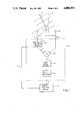
- FIG. 1is a block diagram of a first embodiment of the apparatus for determining time difference of arrival using the cyclic crosscorrelation function of the signal of interest according to the invention
- FIGS. 2a-2eare timing diagrams for the operation sequence of the apparatus of FIG. 1;
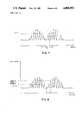
- FIGS. 3a and 3bare graphical representations of signal amplitudes detected according to the invention and the prior techniques, respectively;
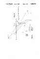
- FIG. 4is a partial block diagram of an alternate embodiment of the invention using optical processing for applying a variable time delay
- FIG. 5is a delay diagram representing the axial arrangement of the optical system of FIG. 4;
- FIG. 6is a block diagram of the apparatus of FIG. 1 including a second processing circuit and an error correction loop;
- FIG. 7is a graphical representation of the signal amplitudes detected by the apparatus of FIG. 6 where the amplitudes are equal.
- FIG. 8is a graphical representation of the signal amplitudes of the apparatus of FIG. 6 where the amplitudes are unequal and the error voltage is negative.
- the apparatus for determining the time difference of arrival of signals from a transmitter to determine the location or line of position of the transmitter relative to a receiveris shown in FIG. 1.
- the transmitted signal of interestis represented as an electromagnetic energy wavefront 2.
- the wavefrontmay be within the radio frequency portion of the electromagnetic energy spectrum and has a carrier frequency of W c which has a modulation at a baud rate of W b .
- the receiverincludes a first antenna 4 and a second antenna 6 which are separated by a given distance d. Owing to the direction of propagation of the wavefront 2 as shown by the line 8, the wavefront is initially received by the first antenna 4 and subsequently received by the second antenna 6. For each delay in time of arrival of a radio frequency wavefront, there is a hyperbolic line of position 10, a subset of which is desired to be determined by the present invention. More particularly, the wavefront 2 will strike the antennas 4, 6 at different times unless the bearing angle ⁇ is equal to 0. It is this difference in time of arrival of the wavefront at the first and second antennas that may be determined directly by the electronic equipment, since this time difference is proportional to the line of position by a hyperbolic function.
- the signals received by the first and second antennasare time varying electrical signals E 1 and E 2 possessing a baud rate W b and are equal except for the time delay between the two signals.
- This time delay Tis also proportional to the line of position 10.
- the determination of the time difference T between the signals by electronic equipmentalso permits the determination therefrom of the desired ultimate quantity, i.e. the line of position.
- the signals E 1 and E 2 from the antennas 4, 6, respectively,are delivered to an electronic signal processing circuit 12 which produces an output signal S that is proportional to the time difference T between the signals E 1 and E 2 .
- the output signal Sis supplied to a conventional line of position device 14 which may be adjusted to respond to the signal S and to display the line of position directly.
- the processing circuit 12includes a variable time delay device 16 connected with the output of the first antenna 4 to variably delay the first signal E 1 .
- the delay device 16also provides an input to the line of position device 14 via a line 18 to correlate a specific delay value with the signal S as the delay device 16 is varied throughout its range. Furthermore, the amount of delay introduced by the delay device 16 may be monitored via the line 18. Accordingly, the signal E 1 ' output from the delay device 16 has a delay relative to the second signal E 2 consisting of the difference between the delay due to the different time of arrivals and the delay introduced by the variable time delay device 16.
- the signals E 1 ' and E 2are delivered to a balanced mixer 20 which multiplies the signals to produce a combined output signal F which contains signals at two times the basic carrier frequency, at the frequency of the baud rate, and at various other frequencies related to the electromagnetic energy wavefront 2.
- a band pass filter 22is connected with the output of the mixer 20 and is tuned to pass that portion of the combined output signal F at the frequency of the baud rate of the signal of interest 2.
- the output of the filter 22thus contains only a signal at the frequency of the baud rate.
- This outputis connected with a peak detector or integrator circuit 24.
- the signal at the frequency of the baud ratehas its amplitude depend on the relative time difference between the two signals E 1 ' and E 2 , before they were multiplied together by the mixer 20. The amplitude peaks when the time difference corresponds to plus or minus one half the baud period, and the amplitude will reach a null when the time difference is 0.
- variable time delay device 16sweeps a time delay over the appropriate range to find the two peaks and the null. At the point where the peak detector 24 reaches the null, the delay introduced by the variable delay device 16 will be equal to the delay due to the differences of arrival.
- the preferred embodiment of the invention of FIG. 1detects the positions of the peaks, and the null which is half way between the peaks. All three points of information, and related knowledge of the signal parameters, are used to determine delay times for which the peaks and nulls occurred.
- the output signal S from the peak detector 24transfers the value of the signal for the three delays introduced by the delay device 16 to provide the peaks and intervening null to the line of position device 14 for bearing angle display. Likewise, the pertinent values for the nulls may be transferred by the line 18 to the display 14.
- FIGS. 2a-2erepresent a timing diagram for operation of the apparatus shown in FIG. 1 for a time t. More particularly, FIG. 2a indicates the signal modulation that is superimposed onto the electromagnetic energy signal as it arrives at the first antenna 4. FIG. 2b illustrates the signal modulation superimposed on the electromagnetic energy signal as it arrives at the second antenna 6. It will be noted that the signals in FIGS. 2a and 2b are equal but for a relative time difference T. This time difference T is related to the line of position 10 of the signal transmitter to the first and second antennas by a hyperbolic function as shown in FIG. 1. The baud rate W b of the signal is shown in FIG. 2a.
- FIG. 2cillustrates the signal modulation that is superimposed onto a carrier frequency signal E 1 ' at the output of the variable time delay device 16. The relative delay of the signal has been altered by a time period ⁇ by the variable time delay device 16.
- the output signal F from the mixer 20is shown in FIG. 2d.
- the mixernot only combines the modulated signals shown in FIGS. 2a and 2c but also the carrier frequencies associated with the modulations of interest and any interference picked up by the first and second antennas.
- the signal Fcontains a multitude of signals comprising various combinations of interference and desired signals.
- FIG. 2eillustrates the frequency of interest among the various signals contained in the output signal F. It is the fundamental frequency component of the signal illustrated in FIG. 2d when the relative difference between the signals of FIGS. 2b and 2c is one half of the baud period. The amplitude of this fundamental component is at the maximum only when the time difference between the signals E 1 ' and E 2 corresponds to one half the baud period. The frequency of this signal of interest is also exactly equal to the baud rate of the signal expressed in Hertz. Interference with other baud rates has a negligible energy contribution at the frequency of the signal baud rate. Thus a band pass filter 22, centered on the baud rate, is used to block the energy related to delays between the two signals. The peak detector 24 monitors the amplitude of the signal at the baud frequency at the output of the filter for the corresponding delay due to differences in time of arrival.
- FIG. 3aillustrates the amplitude of the signal passed by filter 22 as various delays are introduced relative to the signals E 1 ' and E 2 .
- the peak detector 24analyzes these amplitudes and determines the delay corresponding to the null between the two peaks. This null corresponds to the situation where the variable time delay device 16 is compensating exactly for the time of arrival delay, and the resulting two signals are delayed by exactly one half baud with respect to each other.
- the delay informationis passed onto the line of position display 14. Appropriate weighting may be applied to the display device 15 to display the line of position directly, or a chart may accompany a direct reading of the amplitudes, as shown on FIG. 3A, so that an operator may convert such an amplitude to a line of position.
- FIG. 3billustrates the corresponding output for a conventional TDOA system. If there had been a narrow-band interferer present, the peak in FIG. 3b may have been distorted or otherwise obscured.
- FIG. 4A second embodiment of the invention is shown in FIG. 4.
- a coherent light source 26is directed through a first Bragg cell 28.
- E 1 (t) and E 2 (t)Also input to the first Bragg cell 28, through electro-optic transducer 30 and 32, are two signals E 1 (t) and E 2 (t), which are the same as signals E 1 and E 2 shown in FIG. 1 generated by the first and second antennas in response to the incoming signals.
- the Bragg cell 28 and light source 26produce spatial signals E 1 (x) and E 2 (x) as is known in the art.
- the values of E 1 (x) and E 2 (x) presented at any instantinclude
- Tis the maximum propagation time delay of which the first Bragg cell 26 is capable.
- Light from the light source 26 modulated by the signals E 1 and E 2is next directed through a second Bragg cell 34 which is positioned at a right angle with respect to the Bragg cell 28.
- a square wave E 4 (t)having a period l/W b where W b is the baud rate of the incoming signal of interest, is input to the second Bragg cell 34 via an electro-optic transducer 36.
- components of light from the coherent sourceare modulated by E 1 (x+j), E 2 (x+k), and E 3 (y+1) where 0 ⁇ 1 ⁇ U and where U is the maximum propagation time delay of which the second Bragg cell 34 is capable.
- the action of the detector 26is to integrate instantaneous values of E 4 and produce voltages E 5 (j-k,1) which are estimates of the cyclic crosscorrelation function involving E 1 (t) and E 2 (t) and the cyclic frequency W b .
- Specific values of (j-k)correspond to various time delays between the signals E 1 (t) and E 2 (t).
- Specific values of 1correspond to varying the phase of E 3 (t).
- values on the (j-k) axiscorrespond to signal delays and consequently lines of position.
- Values on the 1 axiscorrespond to phase delays between E 3 (t) and the modulating frequency in the incoming signals E 1 or E 2 .
- a plot of timing phase versus angle of arrival delayis shown in FIG. 5.
- this modificationcomprises a second cyclic crosscorrelation circuit in which the two antenna signals are delayed by an additional amount.
- the second circuitincludes a second variable time delay device 40 which receives the delayed signal E 1 ' from the first variable time delay device 16.
- the additionally delayed output signal E 1 " from the second variable time delay device 40is delivered to a second mixer 42 where the signal is mixed with the second signal E 2 from the second antenna 6 to produce a second combined output signal F'.
- This signalis delivered to a second band pass filter 44 of the second cyclic crosscorrelation circuit which is also tuned to pass that portion of the second combined output signal F' at the frequency of the baud rate of the signal of interest.
- a portion of each of the filtered outputsis delivered to a summation device 46.
- the difference voltage at the summation device from the first and second cyclic crosscorrelation circuitsis used as an error control signal C to adjust the time delay of the first variable time delay device 16.
- the voltage differencemay be displayed by a display device 48 for manual coarse adjustment, and may be delivered to an automatic fine adjustment controller 50 for fine adjustment. More particularly, the delay of the first variable time delay device 16 is adjusted so that the error signal C is zero and the outputs of the two circuits are equal. This occurs when the delays associated with the two cyclic crosscorrelation function circuits straddle the actual delay of interest, as will be discussed with reference to FIGS. 7 and 8.
- the two circuitseach generate a signal level corresponding to a cyclic crosscorrelation amplitude for a specific delay.
- the amplitudesare equal and the delays ⁇ 1 and ⁇ 1 + ⁇ 2 clearly straddle the null ⁇ 1 + ⁇ 2/2 corresponding to the bearing of the received signal.
- a negative error voltageis shown where the total delay is too great and the negative error voltage causes the delay controller to decrease the delay of the first device 16.
- the cyclic crosscorrelation method and apparatus according to the inventionoffers a more reliable determination of time difference of arrival in heavy interference than conventional crosscorrelation methods.
- the improved performanceis due to the fact that cyclostationary correlation functions require the existence of a signal modulation component at the examined baud rate if the function is to have a nonzero magnitude.
- interference not possessing the proper baud ratemust eventually produce an output of zero magnitude at the peak detector.
- Such outputscannot affect line of position determinations. This effect is particularly critical to the operation of location systems designed to work with wideband signals of interest because of the greater possibility of interference co-located in frequency with the signal of interest.
Landscapes
- Physics & Mathematics (AREA)
- Engineering & Computer Science (AREA)
- General Physics & Mathematics (AREA)
- Radar, Positioning & Navigation (AREA)
- Remote Sensing (AREA)
- Variable-Direction Aerials And Aerial Arrays (AREA)
Abstract
Description
E.sub.4 =E.sub.1 (x+j)*E.sub.2 (x+k)*E.sub.3 (y+1).
Claims (17)
Priority Applications (1)
| Application Number | Priority Date | Filing Date | Title |
|---|---|---|---|
| US07/147,255US4888593A (en) | 1987-12-15 | 1987-12-15 | Time difference of arrival geolocation method, etc. |
Applications Claiming Priority (1)
| Application Number | Priority Date | Filing Date | Title |
|---|---|---|---|
| US07/147,255US4888593A (en) | 1987-12-15 | 1987-12-15 | Time difference of arrival geolocation method, etc. |
Publications (1)
| Publication Number | Publication Date |
|---|---|
| US4888593Atrue US4888593A (en) | 1989-12-19 |
Family
ID=22520861
Family Applications (1)
| Application Number | Title | Priority Date | Filing Date |
|---|---|---|---|
| US07/147,255Expired - LifetimeUS4888593A (en) | 1987-12-15 | 1987-12-15 | Time difference of arrival geolocation method, etc. |
Country Status (1)
| Country | Link |
|---|---|
| US (1) | US4888593A (en) |
Cited By (70)
| Publication number | Priority date | Publication date | Assignee | Title |
|---|---|---|---|---|
| US5008679A (en)* | 1990-01-31 | 1991-04-16 | Interferometrics Incorporated | Method and system for locating an unknown transmitter |
| US5252983A (en)* | 1991-09-11 | 1993-10-12 | National Space Development Agency Of Japan | Method for reducing side lobes in antenna patterns |
| US5260711A (en)* | 1993-02-19 | 1993-11-09 | Mmtc, Inc. | Difference-in-time-of-arrival direction finders and signal sorters |
| US5285209A (en)* | 1993-04-29 | 1994-02-08 | The United States Of America As Represented By The Secretary Of The Air Force | Angle-of-arrival measurement via spectral estimation of radar time-of-arrival periodicities |
| US5299130A (en)* | 1989-05-01 | 1994-03-29 | Toyoichi Ono | Apparatus for controlling movement of vehicle |
| US5317323A (en)* | 1993-03-05 | 1994-05-31 | E-Systems, Inc. | Passive high accuracy geolocation system and method |
| US5327144A (en)* | 1993-05-07 | 1994-07-05 | Associated Rt, Inc. | Cellular telephone location system |
| US5465289A (en)* | 1993-03-05 | 1995-11-07 | E-Systems, Inc. | Cellular based traffic sensor system |
| US5485163A (en)* | 1994-03-30 | 1996-01-16 | Motorola, Inc. | Personal locator system |
| US5512909A (en)* | 1993-11-17 | 1996-04-30 | Telefonaktiebolaget Lm Ericsson | Method and device for determination of direction |
| US5719584A (en)* | 1996-09-03 | 1998-02-17 | Harris Corporation | System and method for determining the geolocation of a transmitter |
| US5724047A (en)* | 1996-11-27 | 1998-03-03 | Hughes Electronics | Phase and time-difference precision direction finding system |
| WO1998019488A1 (en)* | 1996-10-29 | 1998-05-07 | Nokia Telecommunications Oy | Determination of terminal location in a radio system |
| US5774802A (en)* | 1996-04-10 | 1998-06-30 | Motorola Inc. | Apparatus and method for billing in a wireless communication system |
| USRE35916E (en)* | 1991-12-26 | 1998-10-06 | Dennison; Everett | Cellular telephone system that uses position of a mobile unit to make call management decisions |
| US5852420A (en)* | 1992-04-28 | 1998-12-22 | National Space Development Agency Of Japan | Antenna device |
| US5898402A (en)* | 1997-05-30 | 1999-04-27 | Federal Communications Commission/Compliance And Information Bureau/Equipment Development Group | Wide aperature radio frequency data acquisition system |
| US5936571A (en)* | 1997-01-31 | 1999-08-10 | Lockheed Martin Corporation | Integrated GPS/interference location system |
| US5946611A (en)* | 1991-12-26 | 1999-08-31 | Sycord Limited Partnership | Cellular telephone system that uses position of a mobile unit to make call management decisions |
| US5973643A (en)* | 1997-04-11 | 1999-10-26 | Corsair Communications, Inc. | Method and apparatus for mobile emitter location |
| US6041232A (en)* | 1997-12-23 | 2000-03-21 | Sc-Wireless Inc. | Aggregation of shaped directional receiving antenna array for improved location information |
| US6121927A (en)* | 1996-10-29 | 2000-09-19 | Nokia Telecommunications Oy | Determination of terminal location in a radio system |
| WO2000063718A1 (en)* | 1999-04-20 | 2000-10-26 | Flight Refuelling Limited | Systems and methods for locating subsurface objects |
| US6154657A (en)* | 1997-10-21 | 2000-11-28 | Telefonaktiebolaget Lm Ericsson | Smart subdivision of base station candidates for position location accuracy |
| US6201499B1 (en) | 1998-02-03 | 2001-03-13 | Consair Communications | Time difference of arrival measurement system |
| US6236365B1 (en) | 1996-09-09 | 2001-05-22 | Tracbeam, Llc | Location of a mobile station using a plurality of commercial wireless infrastructures |
| US6249252B1 (en) | 1996-09-09 | 2001-06-19 | Tracbeam Llc | Wireless location using multiple location estimators |
| FR2809823A1 (en)* | 2000-06-06 | 2001-12-07 | Thomson Csf | DIFFERENTIAL MEASUREMENT OF WAVE PROPAGATION TIME AND DEVICE FOR TRACKING THE DIRECTION OF WAVE PROPAGATION |
| US20020107048A1 (en)* | 2000-11-03 | 2002-08-08 | Henry Berger | Pattern detection using the bragg effect at RF Frequencies |
| WO2003009613A1 (en)* | 2001-07-18 | 2003-01-30 | Trueposition, Inc. | Improved method for estimating tdoa and fdoa in a wireless location system |
| US6639552B2 (en)* | 2001-08-30 | 2003-10-28 | Northrop Grumman Corporation | Method of and apparatus for deriving a signal for enabling a radio wave source location to be derived |
| US20030229445A1 (en)* | 2002-05-13 | 2003-12-11 | The Charles Stark Draper Laboratory, Inc. | Low-cost, low-power geolocation system |
| US6847822B1 (en) | 1991-12-26 | 2005-01-25 | Sycord Limited Partnership | Cellular telephone system that uses position of a mobile unit to make call management decisions |
| US20060036346A1 (en)* | 2002-11-26 | 2006-02-16 | Andersen Scott P | System and method for tracking inventory |
| US20060058913A1 (en)* | 2002-11-26 | 2006-03-16 | Andersen Scott P | Inventory tracking |
| US20070004364A1 (en)* | 2003-09-03 | 2007-01-04 | Linnartz Johan P M | Diversity receiver |
| US20070187496A1 (en)* | 2006-02-10 | 2007-08-16 | Andersen Scott P | Inventory tracking system and method |
| US7274332B1 (en) | 1996-09-09 | 2007-09-25 | Tracbeam Llc | Multiple evaluators for evaluation of a purality of conditions |
| US20070233314A1 (en)* | 2006-03-29 | 2007-10-04 | Jungheinrich Aktiengesellschaft | Industrial truck with a load supporting means |
| US7298327B2 (en) | 1996-09-09 | 2007-11-20 | Tracbeam Llc | Geographic location using multiple location estimators |
| US20080055150A1 (en)* | 2006-09-06 | 2008-03-06 | Garmin International, Inc. | Method and system for detecting and decoding air traffic control reply signals |
| US20080122693A1 (en)* | 2006-08-08 | 2008-05-29 | Garmin International, Inc. | Active phased array antenna for aircraft surveillance systems |
| US20080204310A1 (en)* | 2007-02-28 | 2008-08-28 | Garmin International, Inc. | Methods and systems for frequency independent bearing detection |
| US20080284637A1 (en)* | 2007-02-28 | 2008-11-20 | Garmin International, Inc. | Digital tas transmitter and receiver systems and methods |
| US20090109085A1 (en)* | 2006-08-07 | 2009-04-30 | Garmin International, Inc. | Method and system for calibrating an antenna array for an aircraft surveillance system |
| US7679561B2 (en) | 2005-01-19 | 2010-03-16 | The Charles Stark Draper Laboratory, Inc. | Systems and methods for positioning using multipath signals |
| US7714778B2 (en) | 1997-08-20 | 2010-05-11 | Tracbeam Llc | Wireless location gateway and applications therefor |
| US20110001658A1 (en)* | 2009-07-02 | 2011-01-06 | Noble William B | System and method for precision geolocation utilizing multiple sensing modalities |
| US7903029B2 (en) | 1996-09-09 | 2011-03-08 | Tracbeam Llc | Wireless location routing applications and architecture therefor |
| US20110098001A1 (en)* | 2008-04-23 | 2011-04-28 | Elsom-Cook Mark | Short range rf monitoring system |
| US7973716B2 (en) | 2005-01-19 | 2011-07-05 | The Charles Stark Draper Laboratory, Inc. | Systems and methods for transparency mapping using multipath signals |
| US8082096B2 (en) | 2001-05-22 | 2011-12-20 | Tracbeam Llc | Wireless location routing applications and architecture therefor |
| US20110309982A1 (en)* | 2010-06-22 | 2011-12-22 | Raytheon Company | Receiving station and methods for determining an angle-of-arrival of short-duration signals using surface-acoustic-wave (saw) devices |
| WO2011158056A1 (en)* | 2010-06-19 | 2011-12-22 | Nokia Corporation | Method and apparatus for estimating direction of arrival |
| US8135413B2 (en) | 1998-11-24 | 2012-03-13 | Tracbeam Llc | Platform and applications for wireless location and other complex services |
| US8279119B2 (en) | 2005-01-19 | 2012-10-02 | The Charles Stark Draper Laboratory, Inc. | Systems and methods for transparency mapping using multipath signals |
| US8370054B2 (en) | 2005-03-24 | 2013-02-05 | Google Inc. | User location driven identification of service vehicles |
| US8694025B2 (en) | 1999-09-24 | 2014-04-08 | Dennis Dupray | Geographically constrained network services |
| US8774837B2 (en) | 2011-04-30 | 2014-07-08 | John Anthony Wright | Methods, systems and apparatuses of emergency vehicle locating and the disruption thereof |
| US9134398B2 (en) | 1996-09-09 | 2015-09-15 | Tracbeam Llc | Wireless location using network centric location estimators |
| US9538493B2 (en) | 2010-08-23 | 2017-01-03 | Finetrak, Llc | Locating a mobile station and applications therefor |
| US9875492B2 (en) | 2001-05-22 | 2018-01-23 | Dennis J. Dupray | Real estate transaction system |
| CN109564272A (en)* | 2016-08-12 | 2019-04-02 | 阿尔卡特朗讯 | Location detection of user equipment within a wireless telecommunication network |
| US10641861B2 (en) | 2000-06-02 | 2020-05-05 | Dennis J. Dupray | Services and applications for a communications network |
| US10684350B2 (en) | 2000-06-02 | 2020-06-16 | Tracbeam Llc | Services and applications for a communications network |
| US20210313682A1 (en)* | 2018-08-22 | 2021-10-07 | Samsung Electronics Co., Ltd. | Method for adjusting phase of signal to be input to multiple antennas, and electronic device implementing method |
| US20220003829A1 (en)* | 2020-07-06 | 2022-01-06 | ColdQuanta, Inc. | Rydberg-molecule-based microwave direction finding |
| JP2024520016A (en)* | 2021-05-26 | 2024-05-21 | レイセオン カンパニー | Real-time radio mapping using correlation passive receivers |
| US12105130B2 (en) | 2019-01-23 | 2024-10-01 | ColdQuanta, Inc. | Microwave sensor using Autler-Townes splitting |
| US12292526B2 (en) | 2021-05-26 | 2025-05-06 | Raytheon Company | Wireless mapping in real-time using correlative passive receiver |
Citations (7)
| Publication number | Priority date | Publication date | Assignee | Title |
|---|---|---|---|---|
| US3196439A (en)* | 1961-05-15 | 1965-07-20 | Marconi Co Ltd | Radio direction finders |
| US3870998A (en)* | 1959-01-22 | 1975-03-11 | Dewey Electronic Corp | Apparatus for measuring and summing time differences |
| US4000466A (en)* | 1975-05-22 | 1976-12-28 | Iowa State University Research Foundation, Inc. | Apparatus for time-interval measurement |
| US4198634A (en)* | 1971-09-30 | 1980-04-15 | The United States Of America As Represented By The Secretary Of The Navy | Optical autocorrelator signal processor |
| US4204655A (en)* | 1978-11-29 | 1980-05-27 | The United States Of America As Represented By The Secretary Of The Navy | Broadband interferometer and direction finding missile guidance system |
| US4486757A (en)* | 1981-10-26 | 1984-12-04 | American Nucleonics Corp. | Automatic direction finder |
| US4638321A (en)* | 1984-06-01 | 1987-01-20 | Eaton Corporation | Unambiguous wide baseline interferometer |
- 1987
- 1987-12-15USUS07/147,255patent/US4888593A/ennot_activeExpired - Lifetime
Patent Citations (7)
| Publication number | Priority date | Publication date | Assignee | Title |
|---|---|---|---|---|
| US3870998A (en)* | 1959-01-22 | 1975-03-11 | Dewey Electronic Corp | Apparatus for measuring and summing time differences |
| US3196439A (en)* | 1961-05-15 | 1965-07-20 | Marconi Co Ltd | Radio direction finders |
| US4198634A (en)* | 1971-09-30 | 1980-04-15 | The United States Of America As Represented By The Secretary Of The Navy | Optical autocorrelator signal processor |
| US4000466A (en)* | 1975-05-22 | 1976-12-28 | Iowa State University Research Foundation, Inc. | Apparatus for time-interval measurement |
| US4204655A (en)* | 1978-11-29 | 1980-05-27 | The United States Of America As Represented By The Secretary Of The Navy | Broadband interferometer and direction finding missile guidance system |
| US4486757A (en)* | 1981-10-26 | 1984-12-04 | American Nucleonics Corp. | Automatic direction finder |
| US4638321A (en)* | 1984-06-01 | 1987-01-20 | Eaton Corporation | Unambiguous wide baseline interferometer |
Non-Patent Citations (2)
| Title |
|---|
| Boyles et al., "Cycloergodic Properties of Discrete-Parameter Nonstationary Stochastic Processes", IEEE Transactions on Information Theory, vol. IT-29, No. 1, Jan. 1983, pp. 105-114. |
| Boyles et al., Cycloergodic Properties of Discrete Parameter Nonstationary Stochastic Processes , IEEE Transactions on Information Theory, vol. IT 29, No. 1, Jan. 1983, pp. 105 114.* |
Cited By (123)
| Publication number | Priority date | Publication date | Assignee | Title |
|---|---|---|---|---|
| US5299130A (en)* | 1989-05-01 | 1994-03-29 | Toyoichi Ono | Apparatus for controlling movement of vehicle |
| US5008679A (en)* | 1990-01-31 | 1991-04-16 | Interferometrics Incorporated | Method and system for locating an unknown transmitter |
| US5252983A (en)* | 1991-09-11 | 1993-10-12 | National Space Development Agency Of Japan | Method for reducing side lobes in antenna patterns |
| US6847822B1 (en) | 1991-12-26 | 2005-01-25 | Sycord Limited Partnership | Cellular telephone system that uses position of a mobile unit to make call management decisions |
| US5946611A (en)* | 1991-12-26 | 1999-08-31 | Sycord Limited Partnership | Cellular telephone system that uses position of a mobile unit to make call management decisions |
| US20050075114A1 (en)* | 1991-12-26 | 2005-04-07 | Sycord Limited Partnership | Cellular telephone system that uses position of a mobile unit to make call management decisions |
| US7289763B2 (en) | 1991-12-26 | 2007-10-30 | Emsat Advanced Geo-Location Technology, Llp | Cellular telephone system that uses position of a mobile unit to make call management decisions |
| USRE35916E (en)* | 1991-12-26 | 1998-10-06 | Dennison; Everett | Cellular telephone system that uses position of a mobile unit to make call management decisions |
| US20080014965A1 (en)* | 1991-12-26 | 2008-01-17 | Emsat Advanced Geo-Location Technology, Llc | Cellular telephone system that uses position of a mobile unit to make call management decisions |
| US5852420A (en)* | 1992-04-28 | 1998-12-22 | National Space Development Agency Of Japan | Antenna device |
| US5260711A (en)* | 1993-02-19 | 1993-11-09 | Mmtc, Inc. | Difference-in-time-of-arrival direction finders and signal sorters |
| US5317323A (en)* | 1993-03-05 | 1994-05-31 | E-Systems, Inc. | Passive high accuracy geolocation system and method |
| US5465289A (en)* | 1993-03-05 | 1995-11-07 | E-Systems, Inc. | Cellular based traffic sensor system |
| US5285209A (en)* | 1993-04-29 | 1994-02-08 | The United States Of America As Represented By The Secretary Of The Air Force | Angle-of-arrival measurement via spectral estimation of radar time-of-arrival periodicities |
| US5608410A (en)* | 1993-05-07 | 1997-03-04 | Associated Rt, Inc. | System for locating a source of bursty transmissions cross reference to related applications |
| US5327144A (en)* | 1993-05-07 | 1994-07-05 | Associated Rt, Inc. | Cellular telephone location system |
| US5512909A (en)* | 1993-11-17 | 1996-04-30 | Telefonaktiebolaget Lm Ericsson | Method and device for determination of direction |
| US5485163A (en)* | 1994-03-30 | 1996-01-16 | Motorola, Inc. | Personal locator system |
| US5774802A (en)* | 1996-04-10 | 1998-06-30 | Motorola Inc. | Apparatus and method for billing in a wireless communication system |
| US6256504B1 (en) | 1996-04-10 | 2001-07-03 | Motorola, Inc. | Apparatus and method for billing in a wireless communication system |
| US5719584A (en)* | 1996-09-03 | 1998-02-17 | Harris Corporation | System and method for determining the geolocation of a transmitter |
| US8994591B2 (en) | 1996-09-09 | 2015-03-31 | Tracbeam Llc | Locating a mobile station and applications therefor |
| US7764231B1 (en) | 1996-09-09 | 2010-07-27 | Tracbeam Llc | Wireless location using multiple mobile station location techniques |
| US7525484B2 (en) | 1996-09-09 | 2009-04-28 | Tracbeam Llc | Gateway and hybrid solutions for wireless location |
| US7298327B2 (en) | 1996-09-09 | 2007-11-20 | Tracbeam Llc | Geographic location using multiple location estimators |
| US7274332B1 (en) | 1996-09-09 | 2007-09-25 | Tracbeam Llc | Multiple evaluators for evaluation of a purality of conditions |
| US7812766B2 (en) | 1996-09-09 | 2010-10-12 | Tracbeam Llc | Locating a mobile station and applications therefor |
| US6236365B1 (en) | 1996-09-09 | 2001-05-22 | Tracbeam, Llc | Location of a mobile station using a plurality of commercial wireless infrastructures |
| US6249252B1 (en) | 1996-09-09 | 2001-06-19 | Tracbeam Llc | Wireless location using multiple location estimators |
| US7903029B2 (en) | 1996-09-09 | 2011-03-08 | Tracbeam Llc | Wireless location routing applications and architecture therefor |
| US8032153B2 (en) | 1996-09-09 | 2011-10-04 | Tracbeam Llc | Multiple location estimators for wireless location |
| US6952181B2 (en) | 1996-09-09 | 2005-10-04 | Tracbeam, Llc | Locating a mobile station using a plurality of wireless networks and applications therefor |
| US9277525B2 (en) | 1996-09-09 | 2016-03-01 | Tracbeam, Llc | Wireless location using location estimators |
| US9060341B2 (en) | 1996-09-09 | 2015-06-16 | Tracbeam, Llc | System and method for hybriding wireless location techniques |
| US9237543B2 (en) | 1996-09-09 | 2016-01-12 | Tracbeam, Llc | Wireless location using signal fingerprinting and other location estimators |
| US9134398B2 (en) | 1996-09-09 | 2015-09-15 | Tracbeam Llc | Wireless location using network centric location estimators |
| US6121927A (en)* | 1996-10-29 | 2000-09-19 | Nokia Telecommunications Oy | Determination of terminal location in a radio system |
| AU724594B2 (en)* | 1996-10-29 | 2000-09-28 | Nokia Networks Oy | Determination of terminal location in a radio system |
| WO1998019488A1 (en)* | 1996-10-29 | 1998-05-07 | Nokia Telecommunications Oy | Determination of terminal location in a radio system |
| US5724047A (en)* | 1996-11-27 | 1998-03-03 | Hughes Electronics | Phase and time-difference precision direction finding system |
| US5936571A (en)* | 1997-01-31 | 1999-08-10 | Lockheed Martin Corporation | Integrated GPS/interference location system |
| US5973643A (en)* | 1997-04-11 | 1999-10-26 | Corsair Communications, Inc. | Method and apparatus for mobile emitter location |
| US5898402A (en)* | 1997-05-30 | 1999-04-27 | Federal Communications Commission/Compliance And Information Bureau/Equipment Development Group | Wide aperature radio frequency data acquisition system |
| US7714778B2 (en) | 1997-08-20 | 2010-05-11 | Tracbeam Llc | Wireless location gateway and applications therefor |
| US6154657A (en)* | 1997-10-21 | 2000-11-28 | Telefonaktiebolaget Lm Ericsson | Smart subdivision of base station candidates for position location accuracy |
| US6041232A (en)* | 1997-12-23 | 2000-03-21 | Sc-Wireless Inc. | Aggregation of shaped directional receiving antenna array for improved location information |
| US6201499B1 (en) | 1998-02-03 | 2001-03-13 | Consair Communications | Time difference of arrival measurement system |
| US8135413B2 (en) | 1998-11-24 | 2012-03-13 | Tracbeam Llc | Platform and applications for wireless location and other complex services |
| GB2360595A (en)* | 1999-04-20 | 2001-09-26 | Flight Refueling Ltd | Systems and methods for locating subsurface objects |
| GB2360595B (en)* | 1999-04-20 | 2003-11-19 | Flight Refueling Ltd | Systems and methods for locating subsurface objects |
| US6510106B2 (en) | 1999-04-20 | 2003-01-21 | Flight Refuelling Limited | Systems and methods for locating subsurface objects |
| WO2000063718A1 (en)* | 1999-04-20 | 2000-10-26 | Flight Refuelling Limited | Systems and methods for locating subsurface objects |
| US9078101B2 (en) | 1999-09-24 | 2015-07-07 | Dennis Dupray | Geographically constrained network services |
| US10455356B2 (en) | 1999-09-24 | 2019-10-22 | Dennis J. Dupray | Network services dependent upon geographical constraints |
| US8694025B2 (en) | 1999-09-24 | 2014-04-08 | Dennis Dupray | Geographically constrained network services |
| US9699609B2 (en) | 1999-09-24 | 2017-07-04 | Dennis J. Dupray | Network services dependent upon geographical constraints |
| US11765545B2 (en) | 1999-09-24 | 2023-09-19 | Dennis Dupray | Network services dependent on geographical constraints |
| US11971491B2 (en) | 2000-06-02 | 2024-04-30 | Mobile Maven Llc | Services and applications for a communications network |
| US10684350B2 (en) | 2000-06-02 | 2020-06-16 | Tracbeam Llc | Services and applications for a communications network |
| US10641861B2 (en) | 2000-06-02 | 2020-05-05 | Dennis J. Dupray | Services and applications for a communications network |
| EP1162473A1 (en)* | 2000-06-06 | 2001-12-12 | Thales | Time difference of arrival meter and direction finding device |
| FR2809823A1 (en)* | 2000-06-06 | 2001-12-07 | Thomson Csf | DIFFERENTIAL MEASUREMENT OF WAVE PROPAGATION TIME AND DEVICE FOR TRACKING THE DIRECTION OF WAVE PROPAGATION |
| US6990360B2 (en)* | 2000-11-03 | 2006-01-24 | The United States Of America As Represented By The Secretary Of The Army | Pattern detection using the Bragg Effect at RF frequencies |
| US20020107048A1 (en)* | 2000-11-03 | 2002-08-08 | Henry Berger | Pattern detection using the bragg effect at RF Frequencies |
| US9875492B2 (en) | 2001-05-22 | 2018-01-23 | Dennis J. Dupray | Real estate transaction system |
| US11610241B2 (en) | 2001-05-22 | 2023-03-21 | Mobile Maven Llc | Real estate transaction system |
| US8082096B2 (en) | 2001-05-22 | 2011-12-20 | Tracbeam Llc | Wireless location routing applications and architecture therefor |
| GB2395080A (en)* | 2001-07-18 | 2004-05-12 | Trueposition Inc | Improved method for estimating TDOA and FDOA in a wireless location system |
| WO2003009613A1 (en)* | 2001-07-18 | 2003-01-30 | Trueposition, Inc. | Improved method for estimating tdoa and fdoa in a wireless location system |
| US6876859B2 (en) | 2001-07-18 | 2005-04-05 | Trueposition, Inc. | Method for estimating TDOA and FDOA in a wireless location system |
| GB2395080B (en)* | 2001-07-18 | 2005-03-23 | Trueposition Inc | Improved method for estimating TDOA and FDOA in a wireless location system |
| US6639552B2 (en)* | 2001-08-30 | 2003-10-28 | Northrop Grumman Corporation | Method of and apparatus for deriving a signal for enabling a radio wave source location to be derived |
| US20030229445A1 (en)* | 2002-05-13 | 2003-12-11 | The Charles Stark Draper Laboratory, Inc. | Low-cost, low-power geolocation system |
| US6934626B2 (en) | 2002-05-13 | 2005-08-23 | The Charles Stark Draper Laboratory, Inc. | Low-cost, low-power geolocation system |
| US7818088B2 (en) | 2002-11-26 | 2010-10-19 | Rush Tracking Systems, Llc | System and method for tracking inventory |
| US7151979B2 (en) | 2002-11-26 | 2006-12-19 | International Paper Company | System and method for tracking inventory |
| US20110015780A1 (en)* | 2002-11-26 | 2011-01-20 | Scott Paul Andersen | System And Method For Tracking Inventory |
| US20060058913A1 (en)* | 2002-11-26 | 2006-03-16 | Andersen Scott P | Inventory tracking |
| US8774960B2 (en) | 2002-11-26 | 2014-07-08 | Totaltrax, Inc. | System and method for tracking inventory |
| US20060036346A1 (en)* | 2002-11-26 | 2006-02-16 | Andersen Scott P | System and method for tracking inventory |
| US8295974B2 (en) | 2002-11-26 | 2012-10-23 | Rush Tracking Systems, Llc | System and method for tracking inventory |
| US20070004364A1 (en)* | 2003-09-03 | 2007-01-04 | Linnartz Johan P M | Diversity receiver |
| US7761077B2 (en)* | 2003-09-03 | 2010-07-20 | Koninklijke Philips Electronics N.V. | Diversity receiver |
| US7679561B2 (en) | 2005-01-19 | 2010-03-16 | The Charles Stark Draper Laboratory, Inc. | Systems and methods for positioning using multipath signals |
| US8279119B2 (en) | 2005-01-19 | 2012-10-02 | The Charles Stark Draper Laboratory, Inc. | Systems and methods for transparency mapping using multipath signals |
| US7973716B2 (en) | 2005-01-19 | 2011-07-05 | The Charles Stark Draper Laboratory, Inc. | Systems and methods for transparency mapping using multipath signals |
| US20060220872A1 (en)* | 2005-03-01 | 2006-10-05 | Brown Mark A | Mounting bracket |
| US8370054B2 (en) | 2005-03-24 | 2013-02-05 | Google Inc. | User location driven identification of service vehicles |
| US20070187496A1 (en)* | 2006-02-10 | 2007-08-16 | Andersen Scott P | Inventory tracking system and method |
| US7761210B2 (en)* | 2006-03-29 | 2010-07-20 | Jungheinrich Aktiengesellschaft | Industrial truck with a load supporting means |
| US20070233314A1 (en)* | 2006-03-29 | 2007-10-04 | Jungheinrich Aktiengesellschaft | Industrial truck with a load supporting means |
| US7576686B2 (en) | 2006-08-07 | 2009-08-18 | Garmin International, Inc. | Method and system for calibrating an antenna array for an aircraft surveillance system |
| US20090109085A1 (en)* | 2006-08-07 | 2009-04-30 | Garmin International, Inc. | Method and system for calibrating an antenna array for an aircraft surveillance system |
| US7439901B2 (en) | 2006-08-08 | 2008-10-21 | Garmin International, Inc. | Active phased array antenna for aircraft surveillance systems |
| US20080122693A1 (en)* | 2006-08-08 | 2008-05-29 | Garmin International, Inc. | Active phased array antenna for aircraft surveillance systems |
| US20080055150A1 (en)* | 2006-09-06 | 2008-03-06 | Garmin International, Inc. | Method and system for detecting and decoding air traffic control reply signals |
| US20080204310A1 (en)* | 2007-02-28 | 2008-08-28 | Garmin International, Inc. | Methods and systems for frequency independent bearing detection |
| US20080284637A1 (en)* | 2007-02-28 | 2008-11-20 | Garmin International, Inc. | Digital tas transmitter and receiver systems and methods |
| US7825858B2 (en) | 2007-02-28 | 2010-11-02 | Garmin International, Inc. | Methods and systems for frequency independent bearing detection |
| US20110098001A1 (en)* | 2008-04-23 | 2011-04-28 | Elsom-Cook Mark | Short range rf monitoring system |
| US20130059600A1 (en)* | 2008-04-23 | 2013-03-07 | Bigger Than The Wheel Ltd | Short range rf monitoring system |
| US9167548B2 (en)* | 2008-04-23 | 2015-10-20 | Bigger Than The Wheel Ltd. | Short range RF monitoring system |
| US8929821B2 (en)* | 2008-04-23 | 2015-01-06 | Bigger Than The Wheel Ltd. | Short range RF monitoring system |
| US8134493B2 (en) | 2009-07-02 | 2012-03-13 | Raytheon Company | System and method for precision geolocation utilizing multiple sensing modalities |
| US20110001658A1 (en)* | 2009-07-02 | 2011-01-06 | Noble William B | System and method for precision geolocation utilizing multiple sensing modalities |
| WO2011158056A1 (en)* | 2010-06-19 | 2011-12-22 | Nokia Corporation | Method and apparatus for estimating direction of arrival |
| CN102947722B (en)* | 2010-06-19 | 2015-10-21 | 诺基亚公司 | For estimating the method and apparatus of arrival direction |
| CN102947722A (en)* | 2010-06-19 | 2013-02-27 | 诺基亚公司 | Method and apparatus for estimating direction of arrival |
| US8884820B2 (en)* | 2010-06-22 | 2014-11-11 | Raytheon Company | Receiving station and methods for determining an angle-of-arrival of short-duration signals using surface-acoustic-wave (SAW) devices |
| US20110309982A1 (en)* | 2010-06-22 | 2011-12-22 | Raytheon Company | Receiving station and methods for determining an angle-of-arrival of short-duration signals using surface-acoustic-wave (saw) devices |
| US9538493B2 (en) | 2010-08-23 | 2017-01-03 | Finetrak, Llc | Locating a mobile station and applications therefor |
| US12156165B2 (en) | 2010-08-23 | 2024-11-26 | Finetrak, Llc | Resource allocation according to geolocation of mobile communication units related applications |
| US10849089B2 (en) | 2010-08-23 | 2020-11-24 | Finetrak, Llc | Resource allocation according to geolocation of mobile communication units |
| US8774837B2 (en) | 2011-04-30 | 2014-07-08 | John Anthony Wright | Methods, systems and apparatuses of emergency vehicle locating and the disruption thereof |
| CN109564272B (en)* | 2016-08-12 | 2023-11-03 | 阿尔卡特朗讯 | Location detection of user equipment within a wireless telecommunications network |
| CN109564272A (en)* | 2016-08-12 | 2019-04-02 | 阿尔卡特朗讯 | Location detection of user equipment within a wireless telecommunication network |
| US11789107B2 (en)* | 2018-08-22 | 2023-10-17 | Samsung Electronics Co., Ltd. | Method for adjusting phase of signal to be input to multiple antennas, and electronic device implementing method |
| US20210313682A1 (en)* | 2018-08-22 | 2021-10-07 | Samsung Electronics Co., Ltd. | Method for adjusting phase of signal to be input to multiple antennas, and electronic device implementing method |
| US12105130B2 (en) | 2019-01-23 | 2024-10-01 | ColdQuanta, Inc. | Microwave sensor using Autler-Townes splitting |
| US20220003829A1 (en)* | 2020-07-06 | 2022-01-06 | ColdQuanta, Inc. | Rydberg-molecule-based microwave direction finding |
| US11988759B2 (en)* | 2020-07-06 | 2024-05-21 | ColdQuanta, Inc. | Rydberg-molecule-based microwave direction finding |
| JP2024520016A (en)* | 2021-05-26 | 2024-05-21 | レイセオン カンパニー | Real-time radio mapping using correlation passive receivers |
| US12292526B2 (en) | 2021-05-26 | 2025-05-06 | Raytheon Company | Wireless mapping in real-time using correlative passive receiver |
Similar Documents
| Publication | Publication Date | Title |
|---|---|---|
| US4888593A (en) | Time difference of arrival geolocation method, etc. | |
| CA1163701A (en) | Remote object position and orientation locator | |
| US20190101652A1 (en) | Determination of Integrity of Incoming Satellite Signals of Satellite Navigation System | |
| CA1122686A (en) | Locating device | |
| US9651652B2 (en) | Interference cancellation system for location and direction finding | |
| US4316191A (en) | Low angle radar processing means | |
| US4996533A (en) | Single station radar ocean surface current mapper | |
| Ellison et al. | Combined wireless ranging and frequency transfer for internode coordination in open-loop coherent distributed antenna arrays | |
| GB650114A (en) | Improvements in or relating to distance measuring devices utilising reflected wave energy | |
| JPS63503012A (en) | Zero processing receiving device and method | |
| US20210075100A1 (en) | Anti-Jamming System | |
| US6624783B1 (en) | Digital array stretch processor employing two delays | |
| Leavitt et al. | Initial results from a tracking receiver direction finder for whistler mode signals | |
| RU2271019C1 (en) | Method of compensation of signal phase incursions in onboard radar system and onboard radar system with synthesized aperture of antenna for flying vehicles | |
| US3732567A (en) | Junction range finder | |
| EP0117946B1 (en) | Co-channel interference measurement system | |
| US4870420A (en) | Signal acquisition apparatus and method | |
| US3940769A (en) | Binaural auditory presentation apparatus | |
| Read | Review of conventional tactical radio direction finding systems | |
| Demmel | Practical aspects of design and application of direction-finding systems | |
| Shcherbyna et al. | Prospect for using low-element adaptive antenna systems for radio monitoring stations | |
| Noon et al. | Correction of I/Q errors in homodyne step frequency radar refocuses range profiles | |
| US6862922B2 (en) | Radio wave measurement of surface roughness through electromagnetic boundary conditions | |
| JP3570571B2 (en) | Wave field strength estimation method | |
| US3274599A (en) | Radio direction finder system |
Legal Events
| Date | Code | Title | Description |
|---|---|---|---|
| AS | Assignment | Owner name:SIGNAL SCIENCE, INC., 2985 KIFER ROAD, SANTA CLARA Free format text:ASSIGNMENT OF ASSIGNORS INTEREST.;ASSIGNORS:FRIEDMAN, JOSEPH S.;KING, JOHN P.;PRIDE, JOSEPH P. III;REEL/FRAME:004875/0759 Effective date:19871210 Owner name:SIGNAL SCIENCE, INC., A CORP. OF CA,CALIFORNIA Free format text:ASSIGNMENT OF ASSIGNORS INTEREST;ASSIGNORS:FRIEDMAN, JOSEPH S.;KING, JOHN P.;PRIDE, JOSEPH P. III;REEL/FRAME:004875/0759 Effective date:19871210 | |
| AS | Assignment | Owner name:UNITED STATES OF AMERICA, THE, AS REPRESENTED BY T Free format text:ASSIGNMENT OF ASSIGNORS INTEREST.;ASSIGNOR:FRIEDMAN, JOSEPH S.;REEL/FRAME:005208/0348 Effective date:19890810 Owner name:SIGNAL SCIENCE, INC., CALIFORNIA Free format text:ASSIGNMENT OF ASSIGNORS INTEREST.;ASSIGNOR:UNITED STATES OF AMERICA, THE, AS REPRESENTED BY THE DIRECTOR OF THE NATIONAL SECURITY AGENCY;REEL/FRAME:005208/0351 Effective date:19890810 | |
| STCF | Information on status: patent grant | Free format text:PATENTED CASE | |
| FEPP | Fee payment procedure | Free format text:PAYOR NUMBER ASSIGNED (ORIGINAL EVENT CODE: ASPN); ENTITY STATUS OF PATENT OWNER: SMALL ENTITY | |
| FPAY | Fee payment | Year of fee payment:4 | |
| AS | Assignment | Owner name:SILICON VALLEY BANK, CALIFORNIA Free format text:SECURITY INTEREST;ASSIGNOR:SIGNAL SCIENCE, INC.;REEL/FRAME:007439/0269 Effective date:19950215 | |
| FPAY | Fee payment | Year of fee payment:8 | |
| AS | Assignment | Owner name:CONDOR SYSTEMS, INC., CALIFORNIA Free format text:ASSIGNMENT OF ASSIGNORS INTEREST;ASSIGNOR:SIGNAL SCIENCE, INCORPORATED;REEL/FRAME:010425/0451 Effective date:19991015 | |
| AS | Assignment | Owner name:SIGNAL SCIENCE, INC., CALIFORNIA Free format text:RELEASE OF SECUIRTY AGREEMENT;ASSIGNOR:SILICON VALLEY BANK;REEL/FRAME:010437/0268 Effective date:19991015 | |
| FEPP | Fee payment procedure | Free format text:PAYER NUMBER DE-ASSIGNED (ORIGINAL EVENT CODE: RMPN); ENTITY STATUS OF PATENT OWNER: SMALL ENTITY | |
| REMI | Maintenance fee reminder mailed | ||
| FPAY | Fee payment | Year of fee payment:12 | |
| SULP | Surcharge for late payment | Year of fee payment:11 | |
| AS | Assignment | Owner name:KEYBANK NATIONAL ASSOCIATION, OHIO Free format text:SECURITY AGREEMENT;ASSIGNOR:ALLEN TELECOM, INC.;REEL/FRAME:015017/0844 Effective date:20020131 | |
| AS | Assignment | Owner name:KEYBANK NATIONAL ASSOCIATION, OHIO Free format text:SECURITY INTEREST;ASSIGNOR:ALLEN TELECOM, INC.;REEL/FRAME:012822/0425 Effective date:20020131 | |
| AS | Assignment | Owner name:ED0 RECONNAISSANCE & SURVEILLANCE SYSTEMS, NEW YOR Free format text:ASSIGNMENT OF ASSIGNORS INTEREST;ASSIGNOR:CONDOR SYSTEMS, INC.;REEL/FRAME:013248/0754 Effective date:20020726 | |
| AS | Assignment | Owner name:CITIBANK, N.A., NEW YORK Free format text:SECURITY AGREEMENT;ASSIGNOR:EDO RECONNAISSANCE AND SURVEILLANCE SYSTEMS, INC.;REEL/FRAME:013532/0737 Effective date:20021108 | |
| AS | Assignment | Owner name:ALLEN TELECOM INC., OHIO Free format text:RELEASE OF SECURITY INTEREST;ASSIGNOR:KEYBANK NATIONAL ASSOCIATION, AS COLLATERAL AGENT;REEL/FRAME:015027/0518 Effective date:20030716 | |
| AS | Assignment | Owner name:EDO RECONNAISSANCE AND SURVEILLANCE SYSTEMS, INC., Free format text:RELEASE BY SECURED PARTY;ASSIGNOR:CITIBANK, N.A.;REEL/FRAME:020617/0833 Effective date:20071220 |