US4888011A - Artificial heart - Google Patents
Artificial heartDownload PDFInfo
- Publication number
- US4888011A US4888011AUS07/216,028US21602888AUS4888011AUS 4888011 AUS4888011 AUS 4888011AUS 21602888 AUS21602888 AUS 21602888AUS 4888011 AUS4888011 AUS 4888011A
- Authority
- US
- United States
- Prior art keywords
- hydraulic
- chamber
- pumping
- section
- blood
- Prior art date
- Legal status (The legal status is an assumption and is not a legal conclusion. Google has not performed a legal analysis and makes no representation as to the accuracy of the status listed.)
- Expired - Lifetime
Links
Images


Classifications
- A—HUMAN NECESSITIES
- A61—MEDICAL OR VETERINARY SCIENCE; HYGIENE
- A61M—DEVICES FOR INTRODUCING MEDIA INTO, OR ONTO, THE BODY; DEVICES FOR TRANSDUCING BODY MEDIA OR FOR TAKING MEDIA FROM THE BODY; DEVICES FOR PRODUCING OR ENDING SLEEP OR STUPOR
- A61M60/00—Blood pumps; Devices for mechanical circulatory actuation; Balloon pumps for circulatory assistance
- A61M60/40—Details relating to driving
- A61M60/424—Details relating to driving for positive displacement blood pumps
- A61M60/427—Details relating to driving for positive displacement blood pumps the force acting on the blood contacting member being hydraulic or pneumatic
- A61M60/43—Details relating to driving for positive displacement blood pumps the force acting on the blood contacting member being hydraulic or pneumatic using vacuum at the blood pump, e.g. to accelerate filling
- A—HUMAN NECESSITIES
- A61—MEDICAL OR VETERINARY SCIENCE; HYGIENE
- A61M—DEVICES FOR INTRODUCING MEDIA INTO, OR ONTO, THE BODY; DEVICES FOR TRANSDUCING BODY MEDIA OR FOR TAKING MEDIA FROM THE BODY; DEVICES FOR PRODUCING OR ENDING SLEEP OR STUPOR
- A61M60/00—Blood pumps; Devices for mechanical circulatory actuation; Balloon pumps for circulatory assistance
- A61M60/10—Location thereof with respect to the patient's body
- A61M60/122—Implantable pumps or pumping devices, i.e. the blood being pumped inside the patient's body
- A61M60/196—Implantable pumps or pumping devices, i.e. the blood being pumped inside the patient's body replacing the entire heart, e.g. total artificial hearts [TAH]
- A—HUMAN NECESSITIES
- A61—MEDICAL OR VETERINARY SCIENCE; HYGIENE
- A61M—DEVICES FOR INTRODUCING MEDIA INTO, OR ONTO, THE BODY; DEVICES FOR TRANSDUCING BODY MEDIA OR FOR TAKING MEDIA FROM THE BODY; DEVICES FOR PRODUCING OR ENDING SLEEP OR STUPOR
- A61M60/00—Blood pumps; Devices for mechanical circulatory actuation; Balloon pumps for circulatory assistance
- A61M60/40—Details relating to driving
- A61M60/424—Details relating to driving for positive displacement blood pumps
- A61M60/427—Details relating to driving for positive displacement blood pumps the force acting on the blood contacting member being hydraulic or pneumatic
- A—HUMAN NECESSITIES
- A61—MEDICAL OR VETERINARY SCIENCE; HYGIENE
- A61M—DEVICES FOR INTRODUCING MEDIA INTO, OR ONTO, THE BODY; DEVICES FOR TRANSDUCING BODY MEDIA OR FOR TAKING MEDIA FROM THE BODY; DEVICES FOR PRODUCING OR ENDING SLEEP OR STUPOR
- A61M60/00—Blood pumps; Devices for mechanical circulatory actuation; Balloon pumps for circulatory assistance
- A61M60/50—Details relating to control
- A61M60/508—Electronic control means, e.g. for feedback regulation
- A61M60/515—Regulation using real-time patient data
- A61M60/531—Regulation using real-time patient data using blood pressure data, e.g. from blood pressure sensors
- A—HUMAN NECESSITIES
- A61—MEDICAL OR VETERINARY SCIENCE; HYGIENE
- A61M—DEVICES FOR INTRODUCING MEDIA INTO, OR ONTO, THE BODY; DEVICES FOR TRANSDUCING BODY MEDIA OR FOR TAKING MEDIA FROM THE BODY; DEVICES FOR PRODUCING OR ENDING SLEEP OR STUPOR
- A61M60/00—Blood pumps; Devices for mechanical circulatory actuation; Balloon pumps for circulatory assistance
- A61M60/50—Details relating to control
- A61M60/508—Electronic control means, e.g. for feedback regulation
- A61M60/538—Regulation using real-time blood pump operational parameter data, e.g. motor current
- A61M60/554—Regulation using real-time blood pump operational parameter data, e.g. motor current of blood pressure
- A—HUMAN NECESSITIES
- A61—MEDICAL OR VETERINARY SCIENCE; HYGIENE
- A61M—DEVICES FOR INTRODUCING MEDIA INTO, OR ONTO, THE BODY; DEVICES FOR TRANSDUCING BODY MEDIA OR FOR TAKING MEDIA FROM THE BODY; DEVICES FOR PRODUCING OR ENDING SLEEP OR STUPOR
- A61M60/00—Blood pumps; Devices for mechanical circulatory actuation; Balloon pumps for circulatory assistance
- A61M60/10—Location thereof with respect to the patient's body
- A61M60/122—Implantable pumps or pumping devices, i.e. the blood being pumped inside the patient's body
- A61M60/126—Implantable pumps or pumping devices, i.e. the blood being pumped inside the patient's body implantable via, into, inside, in line, branching on, or around a blood vessel
- A61M60/148—Implantable pumps or pumping devices, i.e. the blood being pumped inside the patient's body implantable via, into, inside, in line, branching on, or around a blood vessel in line with a blood vessel using resection or like techniques, e.g. permanent endovascular heart assist devices
- A—HUMAN NECESSITIES
- A61—MEDICAL OR VETERINARY SCIENCE; HYGIENE
- A61M—DEVICES FOR INTRODUCING MEDIA INTO, OR ONTO, THE BODY; DEVICES FOR TRANSDUCING BODY MEDIA OR FOR TAKING MEDIA FROM THE BODY; DEVICES FOR PRODUCING OR ENDING SLEEP OR STUPOR
- A61M60/00—Blood pumps; Devices for mechanical circulatory actuation; Balloon pumps for circulatory assistance
- A61M60/40—Details relating to driving
- A61M60/424—Details relating to driving for positive displacement blood pumps
- A61M60/427—Details relating to driving for positive displacement blood pumps the force acting on the blood contacting member being hydraulic or pneumatic
- A61M60/435—Details relating to driving for positive displacement blood pumps the force acting on the blood contacting member being hydraulic or pneumatic with diastole or systole switching by valve means located between the blood pump and the hydraulic or pneumatic energy source
Definitions
- This inventionrelates in general to artificial hearts and more particularly to an artificial heart system that will respond to varying physiological demand and includes mechanisms accommodating the actual flow imbalance between pulmonary and systemic circulations.
- the present inventionutilizes an alternately left-right pumping device with the left and right pumping chambers, each including a membrane or diaphragm separating the chamber into a blood flow section and a hydraulic section.
- left-side blood pump ejectionhydraulic fluid is being pumped from the right hydraulic section through a hydraulic pump into the left hydraulic section, resulting in concurrent filling of the right side blood pump while left side ejection is taking place.
- the hydraulic flowis reversed for right side ejection and left side filling.
- a third hydraulic chamber small in volume compared to the left side hydraulic section and right side hydraulic section of the blood pumping chambers and having fluid communication with the right side hydraulic sectionis preferably incorporated on the proximal (atrial) side of the left pump inflow valve and includes its own flexible diaphragm in contact with blood inflow through the left pump.
- This third chamberserves to maintain the natural imbalance in the left and right side flows by changing the right hydraulic section fluid volume during a beat. Without this additional balancing hydraulic section, the left and right blood pumping chambers would always provide equal stroke volumes. With the incorporation of this additional hydraulic balance chamber, the volume pumped by the right side pump is reduced by the balancing chamber.
- the distribution of hydraulic fluid between the right side chamber volume and the balancing chamber volumeis altered dynamically by the physiological pressure in the pulmonary artery and in the left atrium, thus adjusting the volume pumped by the right side fluid flow chamber on a beat-by-beat basis.
- the flow resistance between the hydraulic section on the right side chamber and the hydraulic balancing chamberis designed to maintain the overall natural flow imbalance.
- the balancing chamberis placed in the left atrial inflow to provide a negative feedback on the right chamber fluid volume.
- a high left atrial pressureindicating too much flow from the right side, will decrease the hydraulic volume in the balancing chamber and increase the hydraulic volume in the right side chamber. The result is to reduce the flow on the right side.
- a low left atrial pressurewill increase the right side flow. This provides a stable feedback to maintain the desired right side flow relative to the left side flow.
- the primary factoris that the membrane of the balancing factor be in contact with blood flow somewhere in the system or in the patient's connecting atria or arteries so that a variation in blood pressure will produce a positioned change in the membrane. While the left atrium is the preferred site for this balancing chamber, other suitable sites include distal to the right side outflow valve, or right atrial inflow.
- An electrohydraulic energy systemdrives the blood pumps employing a hydraulic fluid, typically methyl silicone, operating at physiological pressures.
- a hydraulic fluidtypically methyl silicone
- This hydraulic coupling between the blood pumps and the energy converterallows geometric flexibility.
- the hydraulic fluid and bloodare immiscible with negligible fluid transfer across the interface.
- the energy converterconsists of an unidirectional axial pump driven by a brushless d.c. motor with flow reversal accomplished by a two-position, sliding sleeve valve. There are, then, essentially two moving parts, the pump motor and one of the valving sleeves. The motor sits immersed in the hydraulic fluid which fills the energy system housing. This ensures temperature uniformity of the system. Waste heat is transferred to the blood across the pump diaphragms and from the housing to contacting body fluid and surfaces.
- a simple two-level control strategyresults in a system responsive to physiological demands.
- Sensors in the hydraulic fluidare indicators of the atrial filling pressures.
- Other sensorsdetect full stroke of the left blood pumps.
- motor speed or rate of filling/ejectionand beat rate.
- the systolic/diastolic ratiois held constant.
- the rate of ejectionis incrementally increased for a given beat rate until the pump is ejecting completely. If, in addition to complete ejection full stroke is achieved, then the beat rate is increased. The reverse occurs if fill volumes are too low.
- the strategyis independent of outflow impedances.
- the artificial heart systemreacts (both stroke volume and beat rate) to changes in the available fill volume and adjusts the outflow pressure to accommodate the outflow impedance.
- each pumpis filled by active withdrawal of hydraulic flow, fill characteristics are not determined by mechanical impedances, but can be tailored to a desired characteristic.
- FIG. 1is an illustration generally in perspective view of an artificial heart constructed in accordance with the principles of this invention placed orthotopically in the thoraic space;
- FIG. 2is an illustration generally in diagrammatic form of one embodiment of an artificial heart system constructed in accordance with the principles of this invention
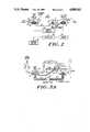
- FIGS. 3a and 3bare a diagrammatic illustration of the operation of the embodiment of FIG. 2.;
- FIG. 4ais an illustration in perspective view of the artificial heart embodiment of FIG. 2.
- FIG. 4bis an illustration in top view of the embodiment of FIG. 4a;
- FIG. 5is a diagram of an algorithm hierarchy for the control system of the artificial heart embodiment of FIG. 1;
- FIG. 6is an illustration in diagrammatic form of the interrelationships of the sensed parameters and the control parameters, together with the resultant physiological parameter of the artificial heart embodiment of FIG. 2;
- FIG. 7is an illustration generally in cross sectional view of a detachable blood pump construction suitable for employment in the embodiment of FIG. 2;
- FIG. 8is an illustration generally in perspective view and partially broken away to show a balancing chamber construction suitable for use in the embodiment of FIG. 2;
- FIGS. 9a and 9bare illustrations in cross sectional view of an energy converter suitable for use in the embodiment of FIG. 2.
- FIG. 1the anatomical placement of the system components is illustrated.
- the systemis intended to replace the ventricles of the natural heart and is inserted within the thoracic cavity in place of the natural heart and coupled to the natural heart right and left atria and also to the pulmonary artery and the aorta.
- the cylindrical energy converter 8 and the blood pumps 5 and 6approximate the shape and volume of the natural heart and are implanted in the pericardial volume vacated by the excised natural heart.
- the blood pumps 5 and 6are seamless with no steps or connectors from proximal to the inflow valve through to the outflow graft distal to the outflow valve.
- the valvesare trileaflet valves placed at the flow inputs and outputs of each of the ventricles.
- the internal blood pump surfaces including the integral trileaflet valvesare fabricated from a non-toxic, non-mutagenic polyetherurethane material made by Abiomed, Inc., Danvers, Mass. under the trademark Angioflex.
- FIG. 2A block diagram of an artificial heart system in accordance with the principles of this invention is illustrated in FIG. 2.
- the two blood pumps 10 and 20, each with a stroke volume typically of 85cc,are connected to the energy converter 32, which includes both a fluid switch and a hydraulic pump.
- the left side pump 10includes a blood flow pumping chamber 11 having a blood input section 18 from the left atrium and a blood output port 14 to the aorta.
- Trileaflet valves 40 and 41have the normal valving function for the blood flow from the pump volume 11.
- the pump 10also includes a hydraulic pumping section 16 which is fluidically coupled to the hydraulic pump 32.
- the right side pump 20is similarly constructed and is coupled between the right atrium at its blood input port 22 and the pulmonary artery at its blood output port 24.
- This pumpalso includes a hydraulic pumping section 26 fluidically coupled to the energy converter 32.
- the left pump 10includes at input cuff 18 a hydraulic section 28 which is fluidically coupled through conduit 30 to the right side hydraulic section 26.
- the volume of hydraulic section 28is small compared to the volume of hydraulic sections 16 and 26 (typically a 1:5 ratio).
- the energy converter 32includes a hydraulic pump which is coupled through a fluid switch to the sections 16 and 26.
- the fluid switch and hydraulic pump in energy converter 32are controlled by a controller 34 which receives electrical power from internal battery 35 and an external battery (not shown) and control signals from sensors 36.
- the converteris more completely described in conjunction with FIG. 9, but provides for an axial flow pump with a sleeve valve which can be electrically switched. Depending upon the position of the sleeve valve, fluid is pumped either in the direction away from hydraulic section 16 and toward hydraulic section 26 or in the other position, away from hydraulic section 26 and toward hydraulic section 16.
- the controller 34controls the position of this switch in accordance with the response to its program and input signals from the sensors 36.
- the pump cycleis as follows. During left side systole, blood is being ejected from the left blood chamber 11 into the aorta. Concurrently the right side blood chamber 21 is being filled from the right atrium. If the blood volume filling the right pump from the right atrium is less than the volume ejected from the left side blood chamber the compensating chamber 28 adjusts the compensating chamber volume formed in the cuff 18 to accommodate this volume difference by virtue of hydraulic fluid flowing from the compensating hydraulic chamber 28 into the right hydraulic section 26. The resultant volume change in the balance chamber in cuff 18 is naturally compensated for by the compliant left atrium during its filling phase.
- the basic control philosophyimplemented on a beat-by-beat basis, is to pump as much blood volume as is available in the atria. This can be achieved by first controlling the hydraulic motor speed to pump the available blood volume at a fixed beat rate. When the available atrial volume exceeds the pump stroke volume, the beat rate is increased. Similarly, in a fill limited situation, the motor speed and the beat rate are reduced to avoid overpumping.
- the motor speedsare controlled by pressure sensing, while the beat rate is controlled by stroke volume sensing.
- the atrial pressuresgovern the motor speeds during the respective fill cycles.
- the motor speedis adjusted to insure that the end diastolic atrial pressure is near zero at the end of a fill cycle.
- the flexible bladder 17 separating blood and hydraulic fluidis tension-free during fill and ejection, and pressure sensors in the hydraulic chambers reflect the atrial pressures. At the end of filling, the bladder rests on a base plate, thus decoupling the hydraulic and the blood pressures.
- a second parameter which indicates the current stroke volumeis used to determine the beat rate of the artificial heart.
- the control for the beat rateis as follows: when the left pump 10 indicates a full stroke, the beat rate is increased, otherwise the beat rate is decreased.
- a compensation volume of 13 ccwill accommodate up to 15% difference between the left and the right side flows.
- the compensating hydraulic volume 28communicates with the right hydraulic section 26.
- the right hydraulic chamber section 26has 85 cc of fluid and the compensation volume 28 has 13 cc of fluid.
- the right side blood chamber 21can contain 72 to 85 cc of blood depending upon how many cubic centimeters of fluid in the compensating volume 28 have transferred to the hydraulic chamber 26. This determines the stroke volume, provided that at the end of right pump ejection the compensation volume 28 is replenished and readied for the next cycle.
- the hydraulic flow (Fc) in and out of this compensation volume 28is governed by the following equation,
- This balance compensation chamberThe design criteria for this balance compensation chamber are: (1) the hydraulic fluid volume must be limited to and not exceed the desired value, and 2) the diaphragm in contact with blood must be free of any supporting structures on the blood-facing side. An annular baseplate sandwiched between two flexible diaphragms will satisfy these criteria.
- the atrial pressure sensorsare placed within the hydraulic section 16 and 26 and, because the hydraulic pressure is in equilibrium with the pressure of the blood in the chambers, these provide for accurate reading of the atrial fill pressure during fill.
- the stroke sensorsare devices which measure the position of the diaphragm 17 which forms the interface between the flow volume and the hydraulic section in the left blood pump, as indicative of whether there is a full stroke.
- FIG. 3aillustrates the operation of this system when the right pump 20 is pumping by virtue of the hydraulic pump forcing hydraulic fluid into the hydraulic section 26, while the left pump is filling with blood returned from the lung under the influence of the membrane 17 withdrawing as the hydraulic fluid is pumped from the left hydraulic section toward the right.
- FIG. 3bis the opposite configuration, in which the left pump is ejecting blood into the aorta under the influence of hydraulic fluid pumped from the right pump section 26 into the left pump section 16, once again aiding the right pump chamber 20 in filling. At the same time the amount of hydraulic fluid in the flow balance compensation chamber 26 is determined by the pressure in the left atrium due to return blood flow.
- FIG. 4a and 4bthere is illustrated the physical configuration of the pumping chambers together with the energy converter showing the location of the inflow and outflow ports.
- the complete control algorithm decision treeis illustrated in FIG. 5.
- the control hierarchyis first fill governed (pressure sensing) followed by beat rate adjustment (full stroke indicator).
- P Lend diastolic pressure in the left chamber
- P osome preset level
- the motor speed during left side diastole and right side systoleis incremented such that during the next beat the flow rate is increased to insure faster filling.
- P L ⁇ P ooverpumping is indicated and the motor speed is decremented.
- two situationscan be encountered.
- the beat ratewill be decremented.
- the second caseoccurs when the bladder bottoms on the hydraulic baseplate (full fill condition). Since the pressure is measured in the hydraulic chamber, P L will be less than P o .
- the beat ratewill be incremented. The beat rate remains unchanged when neither of the above conditions occur.
- This control mechanismcoupled with the flow-pressure characteristics of the axial flow pump, can automatically accommodate aortic and pulmonary pressure variations. For example, if the aortic pressure increases while the right side fill pressure remains unchanged, the motor speed for this half of the cycle will increase during the next beat to yield similar flow but at a higher aortic pressure.
- This algorithmdoes not assume that the peripheral resistance varies inversely with the cardiac output. It is well known that both arterial pressure and cardiac output can increase during exercise.
- This control mechanismdoes not assume any specific relationship between arterial pressure and vascular resistance. Up to the system performance limit, the device will adjust to variations in both the arterial pressure and the vascular resistance.
- FIG. 6shows interrelated plots of parameter changes on a beat-by-beat basis. Adjacent plots share common axes. This plot allows fill pressure, flow, motor speeds (left and right) and beat rate to be intercorrelated and illustrates the behavior of the parameters through a transition from a fill limited case to a stroke volume limited situation.
- the motor speedimmediately increases due to the high filling pressure. Concurrently, the end diastolic pressure decreases and the flow increases. If after the 2nd increment, the pump is at full stroke, the beat rate will increment by one unit every other beat to maintain full stroke. This is accompanied by a further increase in the flow and decrease in the end diastolic pressure, while the motor speed decrements and increments on alternate beats.
- Table Ishows the conditions governing motor speed and beat rate changes in accordance with the logic set forth in the algorithm hierarchy illustrated in FIG. 5.
- FIG. 7there is illustrated in cross sectional view a suitable configuration of a pumping chamber existing in the art.
- the baseplate 50has passages 52 therein to permit flow of the hydraulic fluid against the first diaphragm 55.
- the base plate 50is snapped over a base plate on the energy converter to allow the converter to provide for the flow of hydraulic fluid to extend the diaphragm 55 during systole of the chamber.
- An upper pump diaphragm 57defines the flexible boundary of chamber 11.
- the sealed space (exaggerated for illustration purposes) between the hydraulic diaphragm 55 and the blood pump diaphragm 57is lubricated with hydraulic fluid and thus the change of position of the hydraulic diaphragm 55 under the influence of hydraulic pressure pump in the converter 32 results in a corresponding displacement of the blood pump diaphragm 57.
- the materials used in a circulatory systemmust be durable and biocompatible.
- the tissue contacting the materialsmust be non-mutagenic and non-toxic.
- the blood contacting materialsmust be hemocompatible.
- the materials used for fabricating the pump diaphragms as illustrated in FIG. 7 at 55 and 57,must retain their hemocompatibility and mechanical integrity under the mechanical stresses. Suitable biocompatible materials are medical grade silicones, epoxy, titanium, glass fiber reenforced, epoxy composite, and polyetherurethane, made by Abiomed, Inc. of Danvers, Mass. under the trademark Angioflex.
- FIG. 8is a view of the left inflow cuff 22 containing the imbalance compensation chamber.
- the compensation chambercontains a blood contacting diaphragm 60, a hydraulic diaphragm 64 and annular base plate 66 sandwiched between the two diaphgrams.
- FIGS. 9a and 9billustrate the energy converter in cross sectional view.
- FIG. 9ashows the converter in condition to pump hydraulic fluid from the left hydraulic chamber 16 to the right hydraulic chamber 26, while FIG. 9b shows the converter in condition to pump hydraulic fluid from the right hydraulic chamber 26 to the left hydraulic chamber 16.
- the converterconsists of a unidirectional axial pump 60 having impeller blades to drive fluid from the left chamber 68 into the right chamber 70.
- the direction of outflow from the converteris controlled by the position of sliding sleeve 64 which can be moved axially in response to actuation of the solenoid actuators 65.
- the pump element 60is fitted into a porting sleeve 61, which has slots on both sides of chamber 70, as well as slots on both sides of chamber 68.
- the sliding sleeve 64is formed so that in one position, as shown in 9a, it blocks the slots in the lower portion of the outflow chamber 70 while opening the lower slots in the inflow chamber 68.
- the sleevealso, in this position, blocks the inflow chamber 68 slots in the upper portion of chamber 68 while opening the outflow slots in the upper portion of chamber 70.
- FIG. 9bthe exact opposite situation occurs.
- This arrangementprovides for the hydraulic fluid to move, as indicated by the arrows, in one direction when the sliding sleeve is positioned as in FIG. 9a and in the opposite direction when the sleeve is positioned as in 9b.
- Signals from the control circuitactuate the solenoid actuator 65 and thus control the switching of the direction of flow from the pump.
Landscapes
- Health & Medical Sciences (AREA)
- Engineering & Computer Science (AREA)
- Heart & Thoracic Surgery (AREA)
- Cardiology (AREA)
- Biomedical Technology (AREA)
- Anesthesiology (AREA)
- Mechanical Engineering (AREA)
- Hematology (AREA)
- Life Sciences & Earth Sciences (AREA)
- Animal Behavior & Ethology (AREA)
- General Health & Medical Sciences (AREA)
- Public Health (AREA)
- Veterinary Medicine (AREA)
- Medical Informatics (AREA)
- External Artificial Organs (AREA)
Abstract
Description
F.sub.c =(P.sub.H -P.sub.b)/R
R=ΔP/Q=(8μL)/(πr.sup.4)
TABLE I ______________________________________ CONDITIONS GOVERNING MOTOR SPEED AND BEAT RATE CHANGES Left Right Side Filling Side Filling Control Parameters* Motor Speed Motor Speed Beat Rate ______________________________________ P.sub.L > P.sub.o Increase Increase N.C P.sub.R > P.sub.o P.sub.L > P.sub.o Increase Decrease N.C. P.sub.R > P.sub.o P.sub.L > P.sub.o Decrease Increase N.C. P.sub.R > P.sub.o ##STR1## Decrease Decrease ##STR2## Increase ##STR3## Decrease ##STR4## N.C. ##STR5## N.C. ______________________________________ *P.sub.L --Left ventricular end diastolic pressure P.sub.R --Right ventricular end diastolic pressure P.sub.o --Reference pressure S.sub.D --Left side fill indicator; S.sub.D = 1 is full fill; S.sub.D = 0 is partial fill. S.sub.S --Left side ejection indicator; S.sub.S = 1 is full ejection; S.sub.S = 0 is partial ejection.
Claims (7)
Priority Applications (1)
| Application Number | Priority Date | Filing Date | Title |
|---|---|---|---|
| US07/216,028US4888011A (en) | 1988-07-07 | 1988-07-07 | Artificial heart |
Applications Claiming Priority (1)
| Application Number | Priority Date | Filing Date | Title |
|---|---|---|---|
| US07/216,028US4888011A (en) | 1988-07-07 | 1988-07-07 | Artificial heart |
Publications (1)
| Publication Number | Publication Date |
|---|---|
| US4888011Atrue US4888011A (en) | 1989-12-19 |
Family
ID=22805386
Family Applications (1)
| Application Number | Title | Priority Date | Filing Date |
|---|---|---|---|
| US07/216,028Expired - LifetimeUS4888011A (en) | 1988-07-07 | 1988-07-07 | Artificial heart |
Country Status (1)
| Country | Link |
|---|---|
| US (1) | US4888011A (en) |
Cited By (106)
| Publication number | Priority date | Publication date | Assignee | Title |
|---|---|---|---|---|
| EP0464973A1 (en)* | 1990-06-25 | 1992-01-08 | Klaus Prof. Dr. Ing. Affeld | Medical device generating an alternating flow for driving implantable blood pumps |
| US5135539A (en)* | 1988-01-14 | 1992-08-04 | Etablissement Public: Universite Pierre Et Marie Curie | Quick-connect, totally implantable cardiac prosthesis with floating membranes and removable sensitive elements |
| US5263979A (en)* | 1991-03-19 | 1993-11-23 | Kou Imachi | Artificial heart |
| US5282849A (en)* | 1991-12-19 | 1994-02-01 | University Of Utah Research Foundation | Ventricle assist device with volume displacement chamber |
| US5282850A (en)* | 1989-07-25 | 1994-02-01 | Smith & Nephew Richards, Inc. | Artificial heart components with wear resistant coatings of reduced thrombogenicity |
| US5300113A (en)* | 1990-03-20 | 1994-04-05 | Ministero Dell'universita E Della Ricerca Scientifica E Tecnologica | Cardiac ventricular assistance device particularly for compensating for weakened heart muscle function and for maintaining the vital body functions |
| US5370694A (en)* | 1989-07-25 | 1994-12-06 | Smith & Nephew Richards, Inc. | Zirconium oxide and nitride coated endoprostheses for tissue protection |
| US5569156A (en)* | 1993-09-10 | 1996-10-29 | Ottawa Heart Institute Research Corporation | Electrohydraulic ventricular assist device |
| US5833619A (en)* | 1997-05-15 | 1998-11-10 | L. Vad Technology, Inc. | External blood pressure sensor apparatus and method |
| US6030335A (en)* | 1996-01-26 | 2000-02-29 | Synthelabo Biomedical | Implantable heart-assist pump of the back-pressure balloon type |
| US6042532A (en)* | 1998-03-09 | 2000-03-28 | L. Vad Technology, Inc. | Pressure control system for cardiac assist device |
| US6086527A (en)* | 1998-04-02 | 2000-07-11 | Scimed Life Systems, Inc. | System for treating congestive heart failure |
| US6110100A (en)* | 1998-04-22 | 2000-08-29 | Scimed Life Systems, Inc. | System for stress relieving the heart muscle and for controlling heart function |
| US6132363A (en)* | 1997-09-30 | 2000-10-17 | L.Vad Technology, Inc. | Cardiovascular support control system |
| US6146325A (en)* | 1999-06-03 | 2000-11-14 | Arrow International, Inc. | Ventricular assist device |
| WO2001091828A3 (en)* | 2000-05-30 | 2002-04-04 | Abiomed Inc | Left-right flow control in a two chamber cardiac prosthesis |
| US6511412B1 (en) | 1998-09-30 | 2003-01-28 | L. Vad Technology, Inc. | Cardivascular support control system |
| US6527698B1 (en) | 2000-05-30 | 2003-03-04 | Abiomed, Inc. | Active left-right flow control in a two chamber cardiac prosthesis |
| US6540658B1 (en) | 2000-05-30 | 2003-04-01 | Abiomed, Inc. | Left-right flow control algorithm in a two chamber cardiac prosthesis |
| US6632169B2 (en) | 2001-03-13 | 2003-10-14 | Ltk Enterprises, L.L.C. | Optimized pulsatile-flow ventricular-assist device and total artificial heart |
| US6735532B2 (en) | 1998-09-30 | 2004-05-11 | L. Vad Technology, Inc. | Cardiovascular support control system |
| US6749598B1 (en) | 1999-01-11 | 2004-06-15 | Flowmedica, Inc. | Apparatus and methods for treating congestive heart disease |
| US20040147803A1 (en)* | 2002-10-07 | 2004-07-29 | Hegde Anant V. | Vascular assist device and methods |
| US6994700B2 (en) | 2002-09-20 | 2006-02-07 | Flowmedica, Inc. | Apparatus and method for inserting an intra-aorta catheter through a delivery sheath |
| US20060047180A1 (en)* | 2004-08-25 | 2006-03-02 | Hegde Anant V | Artificial sphincter |
| US7063679B2 (en) | 2002-09-20 | 2006-06-20 | Flowmedica, Inc. | Intra-aortic renal delivery catheter |
| US7122019B1 (en) | 2000-11-28 | 2006-10-17 | Flowmedica Inc. | Intra-aortic renal drug delivery catheter |
| US20070073393A1 (en)* | 2005-09-26 | 2007-03-29 | Abiomed, Inc. | Method and apparatus for pumping blood |
| US20070213579A1 (en)* | 2002-10-07 | 2007-09-13 | Hegde Anant V | Vascular Assist Device and Methods |
| WO2007089500A3 (en)* | 2006-01-30 | 2008-01-24 | Pong-Jeu Lu | Dual-pulsation bi-ventricular assist device |
| US7329236B2 (en) | 1999-01-11 | 2008-02-12 | Flowmedica, Inc. | Intra-aortic renal drug delivery catheter |
| US7364566B2 (en) | 2002-09-20 | 2008-04-29 | Flowmedica, Inc. | Method and apparatus for intra-aortic substance delivery to a branch vessel |
| US7468050B1 (en) | 2002-12-27 | 2008-12-23 | L. Vad Technology, Inc. | Long term ambulatory intra-aortic balloon pump |
| US7481803B2 (en) | 2000-11-28 | 2009-01-27 | Flowmedica, Inc. | Intra-aortic renal drug delivery catheter |
| US7585836B2 (en) | 2004-05-14 | 2009-09-08 | Goodson Iv Harry Burt | Bi-lateral local renal delivery for treating congestive heart failure and for BNP therapy |
| US20090259093A1 (en)* | 2008-04-14 | 2009-10-15 | Bhat Nikhil D | Artificial sphincter with piezoelectric actuator |
| US20090287305A1 (en)* | 2008-05-19 | 2009-11-19 | Amalaha Leonard D | Wholly implantable non-natural heart for humans |
| US20100174231A1 (en)* | 2009-01-07 | 2010-07-08 | Cleveland Clinic Foundation | Method for physiologic control of a continuous flow total artificial heart |
| US7766961B2 (en) | 2003-06-05 | 2010-08-03 | Angio Dynamics, Inc. | Systems and methods for performing bi-lateral interventions or diagnosis in branched body lumens |
| US7771401B2 (en) | 2006-06-08 | 2010-08-10 | Angiodynamics, Inc. | Selective renal cannulation and infusion systems and methods |
| US7780628B1 (en) | 1999-01-11 | 2010-08-24 | Angiodynamics, Inc. | Apparatus and methods for treating congestive heart disease |
| US20100256441A1 (en)* | 2008-12-31 | 2010-10-07 | Pong-Jeu Lu | Cardiac Compression System |
| US20100305692A1 (en)* | 2009-05-27 | 2010-12-02 | Thomas Douglas C | Monitoring of redundant conductors |
| US20110034754A1 (en)* | 2006-06-22 | 2011-02-10 | Matthias Vaska | Devices and methods for absorbing, transferring and delivering heart energy |
| US7914503B2 (en) | 2002-09-20 | 2011-03-29 | Angio Dynamics | Method and apparatus for selective material delivery via an intra-renal catheter |
| US7993325B2 (en) | 2002-09-20 | 2011-08-09 | Angio Dynamics, Inc. | Renal infusion systems and methods |
| US8518011B2 (en) | 2004-03-04 | 2013-08-27 | Angiodynamics, Inc. | Sheath for use in peripheral interventions |
| US8562508B2 (en) | 2009-12-30 | 2013-10-22 | Thoratec Corporation | Mobility-enhancing blood pump system |
| EP2712636A1 (en)* | 2012-09-26 | 2014-04-02 | Fundacja Rozwoju Kardiochirurgii Im. Prof. Zbigniewa Religi | A pediatric heart assist pump |
| US20140323796A1 (en)* | 2013-04-30 | 2014-10-30 | Thoratec Corporation | Cardiac pump with speed adapted for ventricle unloading |
| US9556873B2 (en) | 2013-02-27 | 2017-01-31 | Tc1 Llc | Startup sequence for centrifugal pump with levitated impeller |
| US9623161B2 (en) | 2014-08-26 | 2017-04-18 | Tc1 Llc | Blood pump and method of suction detection |
| US9638202B2 (en) | 2010-09-14 | 2017-05-02 | Tc1 Llc | Centrifugal pump apparatus |
| US9709061B2 (en) | 2013-01-24 | 2017-07-18 | Tc1 Llc | Impeller position compensation using field oriented control |
| US9850906B2 (en) | 2011-03-28 | 2017-12-26 | Tc1 Llc | Rotation drive device and centrifugal pump apparatus employing same |
| US10052420B2 (en) | 2013-04-30 | 2018-08-21 | Tc1 Llc | Heart beat identification and pump speed synchronization |
| US10077777B2 (en) | 2014-05-09 | 2018-09-18 | The Cleveland Clinic Foundation | Artificial heart system implementing suction recognition and avoidance methods |
| US10117983B2 (en) | 2015-11-16 | 2018-11-06 | Tc1 Llc | Pressure/flow characteristic modification of a centrifugal pump in a ventricular assist device |
| US10166318B2 (en) | 2015-02-12 | 2019-01-01 | Tc1 Llc | System and method for controlling the position of a levitated rotor |
| CN109414534A (en)* | 2016-07-01 | 2019-03-01 | 心脏器械股份有限公司 | System and method for maintaining fluid balance |
| US10245361B2 (en) | 2015-02-13 | 2019-04-02 | Tc1 Llc | Impeller suspension mechanism for heart pump |
| US10371152B2 (en) | 2015-02-12 | 2019-08-06 | Tc1 Llc | Alternating pump gaps |
| US10506935B2 (en) | 2015-02-11 | 2019-12-17 | Tc1 Llc | Heart beat identification and pump speed synchronization |
| US10578098B2 (en) | 2005-07-13 | 2020-03-03 | Baxter International Inc. | Medical fluid delivery device actuated via motive fluid |
| US10722631B2 (en) | 2018-02-01 | 2020-07-28 | Shifamed Holdings, Llc | Intravascular blood pumps and methods of use and manufacture |
| US11185677B2 (en) | 2017-06-07 | 2021-11-30 | Shifamed Holdings, Llc | Intravascular fluid movement devices, systems, and methods of use |
| US11478578B2 (en) | 2012-06-08 | 2022-10-25 | Fresenius Medical Care Holdings, Inc. | Medical fluid cassettes and related systems and methods |
| US11511103B2 (en) | 2017-11-13 | 2022-11-29 | Shifamed Holdings, Llc | Intravascular fluid movement devices, systems, and methods of use |
| US11654275B2 (en) | 2019-07-22 | 2023-05-23 | Shifamed Holdings, Llc | Intravascular blood pumps with struts and methods of use and manufacture |
| US11699551B2 (en) | 2020-11-05 | 2023-07-11 | Kardion Gmbh | Device for inductive energy transmission in a human body and use of the device |
| US11724089B2 (en) | 2019-09-25 | 2023-08-15 | Shifamed Holdings, Llc | Intravascular blood pump systems and methods of use and control thereof |
| US11754075B2 (en) | 2018-07-10 | 2023-09-12 | Kardion Gmbh | Impeller for an implantable, vascular support system |
| US11804767B2 (en) | 2018-01-24 | 2023-10-31 | Kardion Gmbh | Magnetic coupling element with a magnetic bearing function |
| US11881721B2 (en) | 2018-05-02 | 2024-01-23 | Kardion Gmbh | Wireless energy transfer system with fault detection |
| US11944805B2 (en) | 2020-01-31 | 2024-04-02 | Kardion Gmbh | Pump for delivering a fluid and method of manufacturing a pump |
| US11964145B2 (en) | 2019-07-12 | 2024-04-23 | Shifamed Holdings, Llc | Intravascular blood pumps and methods of manufacture and use |
| US11996699B2 (en) | 2018-05-02 | 2024-05-28 | Kardion Gmbh | Receiving unit, transmission unit, power transmission system and method for wireless power transmission |
| US12005248B2 (en) | 2018-05-16 | 2024-06-11 | Kardion Gmbh | Rotor bearing system |
| US12064615B2 (en) | 2018-05-30 | 2024-08-20 | Kardion Gmbh | Axial-flow pump for a ventricular assist device and method for producing an axial-flow pump for a ventricular assist device |
| US12076549B2 (en) | 2018-07-20 | 2024-09-03 | Kardion Gmbh | Feed line for a pump unit of a cardiac assistance system, cardiac assistance system and method for producing a feed line for a pump unit of a cardiac assistance system |
| US12102815B2 (en) | 2019-09-25 | 2024-10-01 | Shifamed Holdings, Llc | Catheter blood pumps and collapsible pump housings |
| US12107474B2 (en) | 2018-05-16 | 2024-10-01 | Kardion Gmbh | End-face rotating joint for transmitting torques |
| US12102835B2 (en) | 2018-05-02 | 2024-10-01 | Kardion Gmbh | Transmission unit comprising a transmission coil and a temperature sensor |
| US12121713B2 (en) | 2019-09-25 | 2024-10-22 | Shifamed Holdings, Llc | Catheter blood pumps and collapsible blood conduits |
| US12144976B2 (en) | 2018-06-21 | 2024-11-19 | Kardion Gmbh | Method and device for detecting a wear condition of a ventricular assist device and for operating same, and ventricular assist device |
| US12150647B2 (en) | 2016-06-06 | 2024-11-26 | Kardion Gmbh | Method for punching a lumen and implanting an implant device |
| US12161857B2 (en) | 2018-07-31 | 2024-12-10 | Shifamed Holdings, Llc | Intravascular blood pumps and methods of use |
| US12178554B2 (en) | 2018-06-06 | 2024-12-31 | Kardion Gmbh | Systems and methods for determining a viscosity of a fluid |
| CN119215323A (en)* | 2024-09-18 | 2024-12-31 | 新心医疗器械(北京)有限公司 | An adaptive driving method for a total artificial heart |
| US12194287B2 (en) | 2018-05-30 | 2025-01-14 | Kardion Gmbh | Method of manufacturing electrical conductor tracks in a region of an intravascular blood pump |
| US12201823B2 (en) | 2018-05-30 | 2025-01-21 | Kardion Gmbh | Line device for conducting a blood flow for a heart support system, heart support system, and method for producing a line device |
| US12201821B2 (en) | 2018-06-06 | 2025-01-21 | Kardion Gmbh | Method for determining a flow rate of a fluid flowing through an implanted vascular support system, and implantable vascular support system |
| US12220570B2 (en) | 2018-10-05 | 2025-02-11 | Shifamed Holdings, Llc | Intravascular blood pumps and methods of use |
| US12222267B2 (en) | 2018-06-06 | 2025-02-11 | Kardion Gmbh | Analysis device and method for analyzing a viscosity of a fluid |
| US12230868B2 (en) | 2018-05-02 | 2025-02-18 | Kardion Gmbh | Device for inductive energy transfer into a human body, for example, and use of said device |
| US12233250B2 (en) | 2018-05-02 | 2025-02-25 | Kardion Gmbh | Device for inductive energy transmission into a human body and use thereof |
| US12257424B2 (en) | 2018-06-06 | 2025-03-25 | Kardion Gmbh | Implantable ventricular assist system and method for operating same |
| US12263333B2 (en) | 2018-06-21 | 2025-04-01 | Kardion Gmbh | Stator vane device for guiding the flow of a fluid flowing out of an outlet opening of a ventricular assist device, ventricular assist device with stator vane device, method for operating a stator vane device and manufacturing method |
| US12311160B2 (en) | 2018-06-06 | 2025-05-27 | Kardion Gmbh | Method and system for determining the speed of sound in a fluid in the region of a cardiac support system |
| US12310708B2 (en) | 2018-06-06 | 2025-05-27 | Kardion Gmbh | Systems and methods for determining a flow speed of a fluid flowing through a cardiac assist device |
| US12324906B2 (en) | 2018-06-06 | 2025-06-10 | Kardion Gmbh | Systems and methods for determining a total blood volume flow in a cardiac support system and vascular support system |
| US12377256B2 (en) | 2018-06-06 | 2025-08-05 | Kardion Gmbh | Cardiac support system flow measurement using pressure sensors |
| US12383727B2 (en) | 2018-05-30 | 2025-08-12 | Kardion Gmbh | Motor housing module for a heart support system, and heart support system and method for mounting a heart support system |
| US12390633B2 (en) | 2018-08-07 | 2025-08-19 | Kardion Gmbh | Bearing device for a heart support system, and method for rinsing a space in a bearing device for a heart support system |
| US12403296B2 (en) | 2018-05-30 | 2025-09-02 | Kardion Gmbh | Apparatus for anchoring a ventricular assist system in a blood vessel, operating method, production method for producing an apparatus and ventricular assist system |
| US12409310B2 (en) | 2019-12-11 | 2025-09-09 | Shifamed Holdings, Llc | Descending aorta and vena cava blood pumps |
Citations (4)
| Publication number | Priority date | Publication date | Assignee | Title |
|---|---|---|---|---|
| US3434162A (en)* | 1966-12-13 | 1969-03-25 | Us Health Education & Welfare | Totally implanted artificial heart power system utilizing a rechargeable thermal energy source |
| US4555222A (en)* | 1983-12-23 | 1985-11-26 | International Telephone And Telegraph Corporation | Air-operated diaphragm pump and a valve arrangement therefor |
| US4687424A (en)* | 1983-05-03 | 1987-08-18 | Forschungsgesellschaft Fuer Biomedizinische Technik E.V. | Redundant piston pump for the operation of single or multiple chambered pneumatic blood pumps |
| US4820300A (en)* | 1985-06-20 | 1989-04-11 | Research Corporation Technologies, Inc. | Artificial heart |
- 1988
- 1988-07-07USUS07/216,028patent/US4888011A/ennot_activeExpired - Lifetime
Patent Citations (4)
| Publication number | Priority date | Publication date | Assignee | Title |
|---|---|---|---|---|
| US3434162A (en)* | 1966-12-13 | 1969-03-25 | Us Health Education & Welfare | Totally implanted artificial heart power system utilizing a rechargeable thermal energy source |
| US4687424A (en)* | 1983-05-03 | 1987-08-18 | Forschungsgesellschaft Fuer Biomedizinische Technik E.V. | Redundant piston pump for the operation of single or multiple chambered pneumatic blood pumps |
| US4555222A (en)* | 1983-12-23 | 1985-11-26 | International Telephone And Telegraph Corporation | Air-operated diaphragm pump and a valve arrangement therefor |
| US4820300A (en)* | 1985-06-20 | 1989-04-11 | Research Corporation Technologies, Inc. | Artificial heart |
Cited By (160)
| Publication number | Priority date | Publication date | Assignee | Title |
|---|---|---|---|---|
| US5135539A (en)* | 1988-01-14 | 1992-08-04 | Etablissement Public: Universite Pierre Et Marie Curie | Quick-connect, totally implantable cardiac prosthesis with floating membranes and removable sensitive elements |
| US5370694A (en)* | 1989-07-25 | 1994-12-06 | Smith & Nephew Richards, Inc. | Zirconium oxide and nitride coated endoprostheses for tissue protection |
| US5282850A (en)* | 1989-07-25 | 1994-02-01 | Smith & Nephew Richards, Inc. | Artificial heart components with wear resistant coatings of reduced thrombogenicity |
| US5300113A (en)* | 1990-03-20 | 1994-04-05 | Ministero Dell'universita E Della Ricerca Scientifica E Tecnologica | Cardiac ventricular assistance device particularly for compensating for weakened heart muscle function and for maintaining the vital body functions |
| EP0464973A1 (en)* | 1990-06-25 | 1992-01-08 | Klaus Prof. Dr. Ing. Affeld | Medical device generating an alternating flow for driving implantable blood pumps |
| US5346458A (en)* | 1990-06-25 | 1994-09-13 | Klaus Affeld | Electrohydraulic energy converter for cardiac assist devices and artificial hearts |
| US5263979A (en)* | 1991-03-19 | 1993-11-23 | Kou Imachi | Artificial heart |
| US5282849A (en)* | 1991-12-19 | 1994-02-01 | University Of Utah Research Foundation | Ventricle assist device with volume displacement chamber |
| US5569156A (en)* | 1993-09-10 | 1996-10-29 | Ottawa Heart Institute Research Corporation | Electrohydraulic ventricular assist device |
| US5704891A (en)* | 1993-09-10 | 1998-01-06 | Ottawa Heart Institute Research Corporation | Electrohydraulic ventricular assist device |
| US6030335A (en)* | 1996-01-26 | 2000-02-29 | Synthelabo Biomedical | Implantable heart-assist pump of the back-pressure balloon type |
| US5833619A (en)* | 1997-05-15 | 1998-11-10 | L. Vad Technology, Inc. | External blood pressure sensor apparatus and method |
| US6132363A (en)* | 1997-09-30 | 2000-10-17 | L.Vad Technology, Inc. | Cardiovascular support control system |
| US6042532A (en)* | 1998-03-09 | 2000-03-28 | L. Vad Technology, Inc. | Pressure control system for cardiac assist device |
| US6086527A (en)* | 1998-04-02 | 2000-07-11 | Scimed Life Systems, Inc. | System for treating congestive heart failure |
| US6280377B1 (en) | 1998-04-02 | 2001-08-28 | Scimed Life Systems, Inc. | System for treating congestive heart failure |
| US6110100A (en)* | 1998-04-22 | 2000-08-29 | Scimed Life Systems, Inc. | System for stress relieving the heart muscle and for controlling heart function |
| US6511412B1 (en) | 1998-09-30 | 2003-01-28 | L. Vad Technology, Inc. | Cardivascular support control system |
| US6735532B2 (en) | 1998-09-30 | 2004-05-11 | L. Vad Technology, Inc. | Cardiovascular support control system |
| US7780628B1 (en) | 1999-01-11 | 2010-08-24 | Angiodynamics, Inc. | Apparatus and methods for treating congestive heart disease |
| US7341570B2 (en) | 1999-01-11 | 2008-03-11 | Flowmedica, Inc. | Apparatus and methods for treating congestive heart disease |
| US7335192B2 (en) | 1999-01-11 | 2008-02-26 | Flowmedica, Inc. | Apparatus and methods for treating congestive heart disease |
| US7329236B2 (en) | 1999-01-11 | 2008-02-12 | Flowmedica, Inc. | Intra-aortic renal drug delivery catheter |
| US6749598B1 (en) | 1999-01-11 | 2004-06-15 | Flowmedica, Inc. | Apparatus and methods for treating congestive heart disease |
| US6146325A (en)* | 1999-06-03 | 2000-11-14 | Arrow International, Inc. | Ventricular assist device |
| US6527698B1 (en) | 2000-05-30 | 2003-03-04 | Abiomed, Inc. | Active left-right flow control in a two chamber cardiac prosthesis |
| WO2001091828A3 (en)* | 2000-05-30 | 2002-04-04 | Abiomed Inc | Left-right flow control in a two chamber cardiac prosthesis |
| US6540658B1 (en) | 2000-05-30 | 2003-04-01 | Abiomed, Inc. | Left-right flow control algorithm in a two chamber cardiac prosthesis |
| US7481803B2 (en) | 2000-11-28 | 2009-01-27 | Flowmedica, Inc. | Intra-aortic renal drug delivery catheter |
| US7122019B1 (en) | 2000-11-28 | 2006-10-17 | Flowmedica Inc. | Intra-aortic renal drug delivery catheter |
| US6632169B2 (en) | 2001-03-13 | 2003-10-14 | Ltk Enterprises, L.L.C. | Optimized pulsatile-flow ventricular-assist device and total artificial heart |
| US20040097782A1 (en)* | 2001-03-13 | 2004-05-20 | Theodosios Korakianitis | Optimized pulsatile-flow ventricular-assist device and total artificial heart |
| US7104981B2 (en) | 2002-09-20 | 2006-09-12 | Flowmedica, Inc. | Apparatus and method for inserting an intra-aorta catheter through a delivery sheath |
| US7241273B2 (en) | 2002-09-20 | 2007-07-10 | Flowmedica, Inc. | Intra-aortic renal delivery catheter |
| US7993325B2 (en) | 2002-09-20 | 2011-08-09 | Angio Dynamics, Inc. | Renal infusion systems and methods |
| US7914503B2 (en) | 2002-09-20 | 2011-03-29 | Angio Dynamics | Method and apparatus for selective material delivery via an intra-renal catheter |
| US8012121B2 (en) | 2002-09-20 | 2011-09-06 | Angiodynamics, Inc. | Method and apparatus for selective material delivery via an intra-renal catheter |
| US7063679B2 (en) | 2002-09-20 | 2006-06-20 | Flowmedica, Inc. | Intra-aortic renal delivery catheter |
| US8585678B2 (en) | 2002-09-20 | 2013-11-19 | Angiodynamics, Inc. | Method and apparatus for intra-aortic substance delivery to a branch vessel |
| US7364566B2 (en) | 2002-09-20 | 2008-04-29 | Flowmedica, Inc. | Method and apparatus for intra-aortic substance delivery to a branch vessel |
| US6994700B2 (en) | 2002-09-20 | 2006-02-07 | Flowmedica, Inc. | Apparatus and method for inserting an intra-aorta catheter through a delivery sheath |
| US7563247B2 (en) | 2002-09-20 | 2009-07-21 | Angiodynamics, Inc. | Intra-aortic renal delivery catheter |
| US20080132749A1 (en)* | 2002-10-07 | 2008-06-05 | Hegde Anant V | Vascular Assist Device and Methods |
| US20040147803A1 (en)* | 2002-10-07 | 2004-07-29 | Hegde Anant V. | Vascular assist device and methods |
| US20070213579A1 (en)* | 2002-10-07 | 2007-09-13 | Hegde Anant V | Vascular Assist Device and Methods |
| US7468050B1 (en) | 2002-12-27 | 2008-12-23 | L. Vad Technology, Inc. | Long term ambulatory intra-aortic balloon pump |
| US7766961B2 (en) | 2003-06-05 | 2010-08-03 | Angio Dynamics, Inc. | Systems and methods for performing bi-lateral interventions or diagnosis in branched body lumens |
| US8518011B2 (en) | 2004-03-04 | 2013-08-27 | Angiodynamics, Inc. | Sheath for use in peripheral interventions |
| US7585836B2 (en) | 2004-05-14 | 2009-09-08 | Goodson Iv Harry Burt | Bi-lateral local renal delivery for treating congestive heart failure and for BNP therapy |
| US20060047180A1 (en)* | 2004-08-25 | 2006-03-02 | Hegde Anant V | Artificial sphincter |
| US11384748B2 (en) | 2005-07-13 | 2022-07-12 | Baxter International Inc. | Blood treatment system having pulsatile blood intake |
| US12392335B2 (en) | 2005-07-13 | 2025-08-19 | Baxter International Inc. | Medical fluid pumping system having backflow prevention |
| US10670005B2 (en) | 2005-07-13 | 2020-06-02 | Baxter International Inc. | Diaphragm pumps and pumping systems |
| US10590924B2 (en) | 2005-07-13 | 2020-03-17 | Baxter International Inc. | Medical fluid pumping system including pump and machine chassis mounting regime |
| US10578098B2 (en) | 2005-07-13 | 2020-03-03 | Baxter International Inc. | Medical fluid delivery device actuated via motive fluid |
| US8657875B2 (en) | 2005-09-26 | 2014-02-25 | Abiomed, Inc. | Method and apparatus for pumping blood |
| US20070073393A1 (en)* | 2005-09-26 | 2007-03-29 | Abiomed, Inc. | Method and apparatus for pumping blood |
| US8444545B2 (en) | 2006-01-30 | 2013-05-21 | National Cheng Kung University | Dual-pulsation bi-ventricular assist device |
| US20080306329A1 (en)* | 2006-01-30 | 2008-12-11 | Pong-Jeu Lu | Ventricular Assist Device |
| CN101472627B (en)* | 2006-01-30 | 2013-05-08 | 国立成功大学 | Dual-pulsation bi-ventricular assist device |
| US8500620B2 (en) | 2006-01-30 | 2013-08-06 | National Cheng Kung University | Ventricular assist device |
| US20080300447A1 (en)* | 2006-01-30 | 2008-12-04 | Pong-Jeu Lu | Dual-Pulsation Bi-Ventricular Assist Device |
| WO2007089500A3 (en)* | 2006-01-30 | 2008-01-24 | Pong-Jeu Lu | Dual-pulsation bi-ventricular assist device |
| US7771401B2 (en) | 2006-06-08 | 2010-08-10 | Angiodynamics, Inc. | Selective renal cannulation and infusion systems and methods |
| US20110034754A1 (en)* | 2006-06-22 | 2011-02-10 | Matthias Vaska | Devices and methods for absorbing, transferring and delivering heart energy |
| US8577461B2 (en)* | 2006-06-22 | 2013-11-05 | Matthias Vaska | Devices and methods for absorbing, transferring and delivering heart energy |
| US20090259093A1 (en)* | 2008-04-14 | 2009-10-15 | Bhat Nikhil D | Artificial sphincter with piezoelectric actuator |
| US20090287305A1 (en)* | 2008-05-19 | 2009-11-19 | Amalaha Leonard D | Wholly implantable non-natural heart for humans |
| US8523756B2 (en) | 2008-12-31 | 2013-09-03 | National Cheng Kung University | Cardiac compression system |
| US20100256441A1 (en)* | 2008-12-31 | 2010-10-07 | Pong-Jeu Lu | Cardiac Compression System |
| US8657874B2 (en)* | 2009-01-07 | 2014-02-25 | Cleveland Clinic Foundation | Method for physiologic control of a continuous flow total artificial heart |
| CN102271728B (en)* | 2009-01-07 | 2015-01-28 | 克里夫兰诊所基金会 | Method for physiological control of continuous flow total artificial heart |
| US20100174231A1 (en)* | 2009-01-07 | 2010-07-08 | Cleveland Clinic Foundation | Method for physiologic control of a continuous flow total artificial heart |
| CN102271728A (en)* | 2009-01-07 | 2011-12-07 | 克里夫兰诊所基金会 | Method for physiological control of continuous flow total artificial heart |
| US10350342B2 (en) | 2009-05-27 | 2019-07-16 | Tc1 Llc | Monitoring of redundant conductors |
| US20100305692A1 (en)* | 2009-05-27 | 2010-12-02 | Thomas Douglas C | Monitoring of redundant conductors |
| US9782527B2 (en) | 2009-05-27 | 2017-10-10 | Tc1 Llc | Monitoring of redundant conductors |
| US12201822B2 (en) | 2009-12-30 | 2025-01-21 | Tc1 Llc | Mobility-enhancing blood pump system |
| US8562508B2 (en) | 2009-12-30 | 2013-10-22 | Thoratec Corporation | Mobility-enhancing blood pump system |
| US10029039B2 (en) | 2009-12-30 | 2018-07-24 | Tc1 Llc | Mobility-enhancing blood pump system |
| US10835655B2 (en) | 2009-12-30 | 2020-11-17 | Tc1 Llc | Mobility-enhancing blood pump system |
| US9638202B2 (en) | 2010-09-14 | 2017-05-02 | Tc1 Llc | Centrifugal pump apparatus |
| US9850906B2 (en) | 2011-03-28 | 2017-12-26 | Tc1 Llc | Rotation drive device and centrifugal pump apparatus employing same |
| US11478578B2 (en) | 2012-06-08 | 2022-10-25 | Fresenius Medical Care Holdings, Inc. | Medical fluid cassettes and related systems and methods |
| EP2712636A1 (en)* | 2012-09-26 | 2014-04-02 | Fundacja Rozwoju Kardiochirurgii Im. Prof. Zbigniewa Religi | A pediatric heart assist pump |
| US9709061B2 (en) | 2013-01-24 | 2017-07-18 | Tc1 Llc | Impeller position compensation using field oriented control |
| US9556873B2 (en) | 2013-02-27 | 2017-01-31 | Tc1 Llc | Startup sequence for centrifugal pump with levitated impeller |
| US12343517B2 (en) | 2013-04-30 | 2025-07-01 | Tc1 Llc | Cardiac pump with speed adapted for ventricle unloading |
| US10456513B2 (en) | 2013-04-30 | 2019-10-29 | Tc1 Llc | Cardiac pump with speed adapted for ventricle unloading |
| US20140323796A1 (en)* | 2013-04-30 | 2014-10-30 | Thoratec Corporation | Cardiac pump with speed adapted for ventricle unloading |
| US10052420B2 (en) | 2013-04-30 | 2018-08-21 | Tc1 Llc | Heart beat identification and pump speed synchronization |
| US9713663B2 (en)* | 2013-04-30 | 2017-07-25 | Tc1 Llc | Cardiac pump with speed adapted for ventricle unloading |
| US11724094B2 (en) | 2013-04-30 | 2023-08-15 | Tc1 Llc | Cardiac pump with speed adapted for ventricle unloading |
| US10980928B2 (en) | 2013-04-30 | 2021-04-20 | Tc1 Llc | Cardiac pump with speed adapted for ventricle unloading |
| US10077777B2 (en) | 2014-05-09 | 2018-09-18 | The Cleveland Clinic Foundation | Artificial heart system implementing suction recognition and avoidance methods |
| US9623161B2 (en) | 2014-08-26 | 2017-04-18 | Tc1 Llc | Blood pump and method of suction detection |
| US10856748B2 (en) | 2015-02-11 | 2020-12-08 | Tc1 Llc | Heart beat identification and pump speed synchronization |
| US12213766B2 (en) | 2015-02-11 | 2025-02-04 | Tc1 Llc | Heart beat identification and pump speed synchronization |
| US11712167B2 (en) | 2015-02-11 | 2023-08-01 | Tc1 Llc | Heart beat identification and pump speed synchronization |
| US10506935B2 (en) | 2015-02-11 | 2019-12-17 | Tc1 Llc | Heart beat identification and pump speed synchronization |
| US11015605B2 (en) | 2015-02-12 | 2021-05-25 | Tc1 Llc | Alternating pump gaps |
| US11724097B2 (en) | 2015-02-12 | 2023-08-15 | Tc1 Llc | System and method for controlling the position of a levitated rotor |
| US12285598B2 (en) | 2015-02-12 | 2025-04-29 | Tc1 Llc | System and method for controlling the position of a levitated rotor |
| US12297836B2 (en) | 2015-02-12 | 2025-05-13 | Tc1 Llc | Alternating pump gaps |
| US10371152B2 (en) | 2015-02-12 | 2019-08-06 | Tc1 Llc | Alternating pump gaps |
| US11781551B2 (en) | 2015-02-12 | 2023-10-10 | Tc1 Llc | Alternating pump gaps |
| US10874782B2 (en) | 2015-02-12 | 2020-12-29 | Tc1 Llc | System and method for controlling the position of a levitated rotor |
| US10166318B2 (en) | 2015-02-12 | 2019-01-01 | Tc1 Llc | System and method for controlling the position of a levitated rotor |
| US10245361B2 (en) | 2015-02-13 | 2019-04-02 | Tc1 Llc | Impeller suspension mechanism for heart pump |
| US10117983B2 (en) | 2015-11-16 | 2018-11-06 | Tc1 Llc | Pressure/flow characteristic modification of a centrifugal pump in a ventricular assist device |
| US10888645B2 (en) | 2015-11-16 | 2021-01-12 | Tc1 Llc | Pressure/flow characteristic modification of a centrifugal pump in a ventricular assist device |
| US11639722B2 (en) | 2015-11-16 | 2023-05-02 | Tc1 Llc | Pressure/flow characteristic modification of a centrifugal pump in a ventricular assist device |
| US12150647B2 (en) | 2016-06-06 | 2024-11-26 | Kardion Gmbh | Method for punching a lumen and implanting an implant device |
| CN109414534B (en)* | 2016-07-01 | 2021-07-06 | 心脏器械股份有限公司 | System and method for maintaining fluid balance |
| CN109414534A (en)* | 2016-07-01 | 2019-03-01 | 心脏器械股份有限公司 | System and method for maintaining fluid balance |
| US10376621B2 (en)* | 2016-07-01 | 2019-08-13 | Heartware, Inc. | Systems and methods for maintaining fluid balance |
| US11717670B2 (en) | 2017-06-07 | 2023-08-08 | Shifamed Holdings, LLP | Intravascular fluid movement devices, systems, and methods of use |
| US11185677B2 (en) | 2017-06-07 | 2021-11-30 | Shifamed Holdings, Llc | Intravascular fluid movement devices, systems, and methods of use |
| US11511103B2 (en) | 2017-11-13 | 2022-11-29 | Shifamed Holdings, Llc | Intravascular fluid movement devices, systems, and methods of use |
| US11804767B2 (en) | 2018-01-24 | 2023-10-31 | Kardion Gmbh | Magnetic coupling element with a magnetic bearing function |
| US12076545B2 (en) | 2018-02-01 | 2024-09-03 | Shifamed Holdings, Llc | Intravascular blood pumps and methods of use and manufacture |
| US10722631B2 (en) | 2018-02-01 | 2020-07-28 | Shifamed Holdings, Llc | Intravascular blood pumps and methods of use and manufacture |
| US11229784B2 (en) | 2018-02-01 | 2022-01-25 | Shifamed Holdings, Llc | Intravascular blood pumps and methods of use and manufacture |
| US12233250B2 (en) | 2018-05-02 | 2025-02-25 | Kardion Gmbh | Device for inductive energy transmission into a human body and use thereof |
| US11881721B2 (en) | 2018-05-02 | 2024-01-23 | Kardion Gmbh | Wireless energy transfer system with fault detection |
| US12102835B2 (en) | 2018-05-02 | 2024-10-01 | Kardion Gmbh | Transmission unit comprising a transmission coil and a temperature sensor |
| US12230868B2 (en) | 2018-05-02 | 2025-02-18 | Kardion Gmbh | Device for inductive energy transfer into a human body, for example, and use of said device |
| US11996699B2 (en) | 2018-05-02 | 2024-05-28 | Kardion Gmbh | Receiving unit, transmission unit, power transmission system and method for wireless power transmission |
| US12005248B2 (en) | 2018-05-16 | 2024-06-11 | Kardion Gmbh | Rotor bearing system |
| US12107474B2 (en) | 2018-05-16 | 2024-10-01 | Kardion Gmbh | End-face rotating joint for transmitting torques |
| US12064615B2 (en) | 2018-05-30 | 2024-08-20 | Kardion Gmbh | Axial-flow pump for a ventricular assist device and method for producing an axial-flow pump for a ventricular assist device |
| US12403296B2 (en) | 2018-05-30 | 2025-09-02 | Kardion Gmbh | Apparatus for anchoring a ventricular assist system in a blood vessel, operating method, production method for producing an apparatus and ventricular assist system |
| US12194287B2 (en) | 2018-05-30 | 2025-01-14 | Kardion Gmbh | Method of manufacturing electrical conductor tracks in a region of an intravascular blood pump |
| US12383727B2 (en) | 2018-05-30 | 2025-08-12 | Kardion Gmbh | Motor housing module for a heart support system, and heart support system and method for mounting a heart support system |
| US12201823B2 (en) | 2018-05-30 | 2025-01-21 | Kardion Gmbh | Line device for conducting a blood flow for a heart support system, heart support system, and method for producing a line device |
| US12222267B2 (en) | 2018-06-06 | 2025-02-11 | Kardion Gmbh | Analysis device and method for analyzing a viscosity of a fluid |
| US12257424B2 (en) | 2018-06-06 | 2025-03-25 | Kardion Gmbh | Implantable ventricular assist system and method for operating same |
| US12178554B2 (en) | 2018-06-06 | 2024-12-31 | Kardion Gmbh | Systems and methods for determining a viscosity of a fluid |
| US12201821B2 (en) | 2018-06-06 | 2025-01-21 | Kardion Gmbh | Method for determining a flow rate of a fluid flowing through an implanted vascular support system, and implantable vascular support system |
| US12311160B2 (en) | 2018-06-06 | 2025-05-27 | Kardion Gmbh | Method and system for determining the speed of sound in a fluid in the region of a cardiac support system |
| US12324906B2 (en) | 2018-06-06 | 2025-06-10 | Kardion Gmbh | Systems and methods for determining a total blood volume flow in a cardiac support system and vascular support system |
| US12310708B2 (en) | 2018-06-06 | 2025-05-27 | Kardion Gmbh | Systems and methods for determining a flow speed of a fluid flowing through a cardiac assist device |
| US12377256B2 (en) | 2018-06-06 | 2025-08-05 | Kardion Gmbh | Cardiac support system flow measurement using pressure sensors |
| US12144976B2 (en) | 2018-06-21 | 2024-11-19 | Kardion Gmbh | Method and device for detecting a wear condition of a ventricular assist device and for operating same, and ventricular assist device |
| US12263333B2 (en) | 2018-06-21 | 2025-04-01 | Kardion Gmbh | Stator vane device for guiding the flow of a fluid flowing out of an outlet opening of a ventricular assist device, ventricular assist device with stator vane device, method for operating a stator vane device and manufacturing method |
| US11754075B2 (en) | 2018-07-10 | 2023-09-12 | Kardion Gmbh | Impeller for an implantable, vascular support system |
| US12076549B2 (en) | 2018-07-20 | 2024-09-03 | Kardion Gmbh | Feed line for a pump unit of a cardiac assistance system, cardiac assistance system and method for producing a feed line for a pump unit of a cardiac assistance system |
| US12161857B2 (en) | 2018-07-31 | 2024-12-10 | Shifamed Holdings, Llc | Intravascular blood pumps and methods of use |
| US12390633B2 (en) | 2018-08-07 | 2025-08-19 | Kardion Gmbh | Bearing device for a heart support system, and method for rinsing a space in a bearing device for a heart support system |
| US12220570B2 (en) | 2018-10-05 | 2025-02-11 | Shifamed Holdings, Llc | Intravascular blood pumps and methods of use |
| US11964145B2 (en) | 2019-07-12 | 2024-04-23 | Shifamed Holdings, Llc | Intravascular blood pumps and methods of manufacture and use |
| US11654275B2 (en) | 2019-07-22 | 2023-05-23 | Shifamed Holdings, Llc | Intravascular blood pumps with struts and methods of use and manufacture |
| US12121713B2 (en) | 2019-09-25 | 2024-10-22 | Shifamed Holdings, Llc | Catheter blood pumps and collapsible blood conduits |
| US12102815B2 (en) | 2019-09-25 | 2024-10-01 | Shifamed Holdings, Llc | Catheter blood pumps and collapsible pump housings |
| US11724089B2 (en) | 2019-09-25 | 2023-08-15 | Shifamed Holdings, Llc | Intravascular blood pump systems and methods of use and control thereof |
| US12409310B2 (en) | 2019-12-11 | 2025-09-09 | Shifamed Holdings, Llc | Descending aorta and vena cava blood pumps |
| US11944805B2 (en) | 2020-01-31 | 2024-04-02 | Kardion Gmbh | Pump for delivering a fluid and method of manufacturing a pump |
| US11699551B2 (en) | 2020-11-05 | 2023-07-11 | Kardion Gmbh | Device for inductive energy transmission in a human body and use of the device |
| US12400788B2 (en) | 2020-11-05 | 2025-08-26 | Kardion Gmbh | Device for inductive energy transmission in a human body and use of the device |
| CN119215323A (en)* | 2024-09-18 | 2024-12-31 | 新心医疗器械(北京)有限公司 | An adaptive driving method for a total artificial heart |
Similar Documents
| Publication | Publication Date | Title |
|---|---|---|
| US4888011A (en) | Artificial heart | |
| US5749839A (en) | Direct mechanical bi-ventricular cardiac assist device | |
| US5098370A (en) | Heart assist device | |
| CA1329450C (en) | Quick-connect, totally implantable cardiac prosthesis with floating membranes and removable sensitive elements | |
| US12005247B2 (en) | Pump for artificial circulatory assistance and a pumping system | |
| US4369530A (en) | Hydraulically actuated cardiac prosthesis and method of actuation | |
| US20020103413A1 (en) | Implantable device for utilisation of the hydraulic energy of the heart | |
| JPS61501890A (en) | Electronic control device for artificial heart | |
| CA2625046A1 (en) | Total artificial heart system for auto-regulating flow and pressure balance | |
| HU200679B (en) | Device for helping the work of heart | |
| US5643172A (en) | Tubular circulatory assist device | |
| KR920000460B1 (en) | Blood pump | |
| EP0079373B1 (en) | Hydraulically actuated cardiac prosthesis | |
| US4376312A (en) | Hydraulically actuated cardiac prosthesis | |
| CN116173393A (en) | A positive and negative pressure driven heart pumping system | |
| Choi et al. | A new automatic cardiac output control algorithm for moving actuator total artificial heart by motor current waveform analysis | |
| JP2023518426A (en) | Pressure sensor placement and method | |
| Nosé et al. | Experimental results for chronic left ventricular assist and total artificial heart development | |
| Altieri et al. | Mechanical support for the failing heart | |
| EP4010043B1 (en) | Cardiac chamber prosthesis and related cardiac assistance system | |
| Kung et al. | Self-regulation of an electrohydraulic total artificial heart | |
| Pya et al. | Management of Patients Supported by the Aeson Bioprosthetic Total Artificial Heart | |
| CN119215323A (en) | An adaptive driving method for a total artificial heart | |
| Pya et al. | The Aeson Bioprosthetic Total Artificial Heart | |
| EP4466058A1 (en) | A biventricular assist system |
Legal Events
| Date | Code | Title | Description |
|---|---|---|---|
| AS | Assignment | Owner name:ABIOMED, INC. 33 CHERRY HILL DRIVE, DANVERS, MA 01 Free format text:ASSIGNMENT OF ASSIGNORS INTEREST.;ASSIGNORS:KUNG, ROBERT T. V.;SINGH, PARAM I.;REEL/FRAME:004907/0202 Effective date:19880706 Owner name:ABIOMED, INC.,MASSACHUSETTS Free format text:ASSIGNMENT OF ASSIGNORS INTEREST;ASSIGNORS:KUNG, ROBERT T. V.;SINGH, PARAM I.;REEL/FRAME:004907/0202 Effective date:19880706 | |
| STCF | Information on status: patent grant | Free format text:PATENTED CASE | |
| AS | Assignment | Owner name:ABIOMED, INC., A CORPORATION OF DE, MASSACHUSETTS Free format text:CORRECTIVE ASSIGNMENT TO CORRECT THE STATE OF INCORPORATION OF ASSIGNEE ON REEL 5066, FRAME 750.;ASSIGNOR:ABIOMED, INC.;REEL/FRAME:005756/0559 Effective date:19910529 | |
| FEPP | Fee payment procedure | Free format text:PAYOR NUMBER ASSIGNED (ORIGINAL EVENT CODE: ASPN); ENTITY STATUS OF PATENT OWNER: SMALL ENTITY | |
| CC | Certificate of correction | ||
| FPAY | Fee payment | Year of fee payment:4 | |
| FPAY | Fee payment | Year of fee payment:8 | |
| FEPP | Fee payment procedure | Free format text:PAYER NUMBER DE-ASSIGNED (ORIGINAL EVENT CODE: RMPN); ENTITY STATUS OF PATENT OWNER: SMALL ENTITY Free format text:PAYOR NUMBER ASSIGNED (ORIGINAL EVENT CODE: ASPN); ENTITY STATUS OF PATENT OWNER: SMALL ENTITY | |
| FEPP | Fee payment procedure | Free format text:PAYER NUMBER DE-ASSIGNED (ORIGINAL EVENT CODE: RMPN); ENTITY STATUS OF PATENT OWNER: SMALL ENTITY Free format text:PAYOR NUMBER ASSIGNED (ORIGINAL EVENT CODE: ASPN); ENTITY STATUS OF PATENT OWNER: SMALL ENTITY | |
| FEPP | Fee payment procedure | Free format text:PAYER NUMBER DE-ASSIGNED (ORIGINAL EVENT CODE: RMPN); ENTITY STATUS OF PATENT OWNER: SMALL ENTITY Free format text:PAYOR NUMBER ASSIGNED (ORIGINAL EVENT CODE: ASPN); ENTITY STATUS OF PATENT OWNER: SMALL ENTITY | |
| FPAY | Fee payment | Year of fee payment:12 |