US4887804A - Stage mechanism - Google Patents
Stage mechanismDownload PDFInfo
- Publication number
- US4887804A US4887804AUS07/125,552US12555287AUS4887804AUS 4887804 AUS4887804 AUS 4887804AUS 12555287 AUS12555287 AUS 12555287AUS 4887804 AUS4887804 AUS 4887804A
- Authority
- US
- United States
- Prior art keywords
- stage
- stage portion
- mechanism according
- reference portion
- vibration
- Prior art date
- Legal status (The legal status is an assumption and is not a legal conclusion. Google has not performed a legal analysis and makes no representation as to the accuracy of the status listed.)
- Expired - Lifetime
Links
Images


Classifications
- B—PERFORMING OPERATIONS; TRANSPORTING
- B23—MACHINE TOOLS; METAL-WORKING NOT OTHERWISE PROVIDED FOR
- B23Q—DETAILS, COMPONENTS, OR ACCESSORIES FOR MACHINE TOOLS, e.g. ARRANGEMENTS FOR COPYING OR CONTROLLING; MACHINE TOOLS IN GENERAL CHARACTERISED BY THE CONSTRUCTION OF PARTICULAR DETAILS OR COMPONENTS; COMBINATIONS OR ASSOCIATIONS OF METAL-WORKING MACHINES, NOT DIRECTED TO A PARTICULAR RESULT
- B23Q11/00—Accessories fitted to machine tools for keeping tools or parts of the machine in good working condition or for cooling work; Safety devices specially combined with or arranged in, or specially adapted for use in connection with, machine tools
- B23Q11/0032—Arrangements for preventing or isolating vibrations in parts of the machine
- B—PERFORMING OPERATIONS; TRANSPORTING
- B23—MACHINE TOOLS; METAL-WORKING NOT OTHERWISE PROVIDED FOR
- B23Q—DETAILS, COMPONENTS, OR ACCESSORIES FOR MACHINE TOOLS, e.g. ARRANGEMENTS FOR COPYING OR CONTROLLING; MACHINE TOOLS IN GENERAL CHARACTERISED BY THE CONSTRUCTION OF PARTICULAR DETAILS OR COMPONENTS; COMBINATIONS OR ASSOCIATIONS OF METAL-WORKING MACHINES, NOT DIRECTED TO A PARTICULAR RESULT
- B23Q1/00—Members which are comprised in the general build-up of a form of machine, particularly relatively large fixed members
- B23Q1/25—Movable or adjustable work or tool supports
- B23Q1/26—Movable or adjustable work or tool supports characterised by constructional features relating to the co-operation of relatively movable members; Means for preventing relative movement of such members
- B23Q1/34—Relative movement obtained by use of deformable elements, e.g. piezoelectric, magnetostrictive, elastic or thermally-dilatable elements
- H—ELECTRICITY
- H01—ELECTRIC ELEMENTS
- H01L—SEMICONDUCTOR DEVICES NOT COVERED BY CLASS H10
- H01L21/00—Processes or apparatus adapted for the manufacture or treatment of semiconductor or solid state devices or of parts thereof
- H01L21/67—Apparatus specially adapted for handling semiconductor or electric solid state devices during manufacture or treatment thereof; Apparatus specially adapted for handling wafers during manufacture or treatment of semiconductor or electric solid state devices or components ; Apparatus not specifically provided for elsewhere
- H01L21/68—Apparatus specially adapted for handling semiconductor or electric solid state devices during manufacture or treatment thereof; Apparatus specially adapted for handling wafers during manufacture or treatment of semiconductor or electric solid state devices or components ; Apparatus not specifically provided for elsewhere for positioning, orientation or alignment
Definitions
- This inventionrelates to a stage mechanism usable in semiconductor device manufacturing apparatuses or otherwise, wherein high-precision and high-speed positioning is required.
- stage deviceAn example of such a stage device is disclosed in Japanese Laid-Open Utility Model Application, Laid-Open No. Sho 58-105604. Another example is disclosed in Japanese Laid-Open Patent Application, Laid-Open No. Sho 62-79645, filed in Japan and is commonly assigned herewith.
- each vibration attenuating elementis spaced from the stage with respect to a direction perpendicular to the direction of movement of the stage. Therefore, it is not easy to damp the residual vibration precisely, as desired.
- a stage mechanismhaving a stage portion and a reference portion for supporting the stage portion. Also, the stage mechanism includes a solid damper provided between the stage portion and the reference portion, at a position which is on the direction of movement of the stage portion.
- a damping material having weak stiffnesssuch as rubber, low-elasticity resin, low-elasticity bonding agent or otherwise may be used as the solid damper.
- Another object of the present inventionis to provide a stage mechanism which is specifically adapted to displace and position a stage with high precision and high speed, particularly by use of a specific drive source.
- FIG. 1is a schematic and diagrammatic view of a stage device according to one embodiment of the present invention.
- FIGS. 2A and 2Bare graphs showing data obtained as a result of experiments, made to clarify advantageous effects of the present invention.
- FIGS. 3-5are perspective views, respectively, schematically showing stage devices according to further embodiments of the present invention.
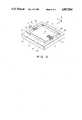
- the stage deviceincludes a reference portion 1 which is a fixed portion and comprises, in this embodiment, a base member.
- the devicefurther includes a stage 2 which is a movable or displaceable member.
- leaf springs 3a-3dwhich are adapted to flexibly support the stage 2 upon the base 1 so that the stage 2 is movable or displaceable relative to the base 1 along an axis Y.
- Each of the leaf springs 3a-3dhas an end thereof fixed to corresponding one of four corners of the stage 2 and another end of each leaf spring is supported by the base 1.
- Each leaf springextends along an axis X which is perpendicular to the Y-axis direction.
- the leaf springs 3a and 3bcooperate with each other to provide a parallel leaf spring mechanism while, on the opposite side of the stage 2, the leaf springs 3c and 3d cooperate with each other to provide another parallel leaf spring mechanism.
- the gaps la-1dthere are formed gaps la-1d.
- each of the gaps la and lcis defined by a space extending in parallel to the X-axis direction.
- each of the gaps lb and ldis defined by a space extending in parallel to the Y-axis direction.
- the stage devicefurther includes an actuator 4 having an end thereof fixed to the base 1 and another end contacting the stage 2.
- the actuator 4comprises a piezoelectric device.
- the actuator 4 comprising a piezoelectric deviceis deformable in the Y-axis direction. By energizing the actuator 4 to cause it to press the stage 2 toward the base 1, the stage 2 is displaced minutely in the Y-axis direction.
- the piezoelectric device 4is disposed in a groove 2a which is formed to extend from one side surface of the stage 2 toward the center O of the stage 2.
- stage device of the present embodimentis arranged so that the pressing force of the piezoelectric device 4 acts exactly upon the "center" of the stage 2 which is with respect to the X-axis direction and a Z-axis direction (a direction perpendicular to the X and Y axes).
- the deviceis further provided with damping rubber members 5 disposed in the gaps lb-1d, respectively, defined between the base 1 and the stage 2.
- Each of the damping rubber members 5has a width, in the Z-axis direction, which is approximately equal to the thickness of the stage 2 in the Z-axis direction. Also, each damping rubber member is disposed symmetrically in the Z-axis direction with respect to the center O of the stage 2.
- the stage devicefurther includes a controlling voltage producing circuit 10 for producing an electric voltage to control the expansion/contraction of the piezoelectric device 4, and a central processing unit 11 for producing instruction signals which are applied to the controlling voltage producing circuit 10.
- the base 1, the stage 2 and the leaf springs 3a-3dare formed by slotting a single and integral plate-like member to define the gaps 1a-1d and the groove 2a. Subsequently, each of the gaps 1b-1d is filled with a liquefied rubber material. The rubber material is set up by cooling, whereby the damping rubber member 5 is formed. Since the amount of displacement of the stage 2 by the deformation of the piezoelectric device 4 is small, such as rubber material as elastically deformable only by a small amount can be satisfactorily used as the damping member.
- the stage 2is displaced with a large acceleration by the pressing force of the piezoelectric device 4.
- the stage device of the present embodimentas compared therewith, use of the damping rubber members 5 effectively avoids such disadvantage.
- each damping rubber member 5is effective to absorb the vibration energy of the stage 2 after it reaches the desired position, with the result that the residual vibration is damped quickly. Therefore, the vibration is stopped in a very short time so that the stage 2 can be positioned promptly at the desired position. Further, the provision of the damping members around the stage 2, by filling, is very effective because not only the vibration component in the direction of displacement of the stage 2 (i.e. in the Y-axis direction) but also vibration components in the other directions can be damped sufficiently and quickly.
- FIGS. 2A and 2BComparison experiments were made to a stage device of the present embodiment having damping rubber members 5 and to a similar stage device but having no such damping rubber member. The results are shown in FIGS. 2A and 2B.
- FIG. 2Ais concerned with the stage device without using any damping rubber member.
- a lower curve Vshows an electric voltage applied to a piezoelectric device from a controlling voltage producing circuit.
- An upper curve ⁇ Yshows displacement of a stage such as at 2 in FIG. 1 in response to the voltage application.
- FIG. 2Bis concerned with the stage device of the present embodiment and the curves V and ⁇ Y corresponds respectively to those shown in FIG. 2A. In both cases, the displacing electric voltage was applied at time t. Comparing FIGS. 2A and 2B, it is seen that the provision of the damping rubber members in the stage device, as in the present embodiment, is effective to ensure high damping property at the time of positioning of the stage 2.
- a low-elasticity resinsuch as polyethylene may be used. If this is desired, the resin in a liquefied state is flown into the gaps lb-1d (FIG. 1) and, when the resin is set up by cooling, damping members are formed. Alternatively, each gap may be filled with a rubber-series bonding agent, the agent when it is set up providing a damping member.
- a suitable setting agentmay be used for the setup of the low-elasticity resin.
- FIG. 3shows a stage device according to a second embodiment of the present invention. Same reference numerals as in the FIG. 1 embodiment are assigned to corresponding elements. Also, while not shown in FIG. 3, an actuator 4 comprising a piezoelectric device is electrically connected to a central processing unit (not shown) by way of a controlling voltage producing circuit (also not shown).
- a damping rubber member 5ais provided between a base 1 and a stage 2.
- the damping rubber member 5ahas been formed separately from the base 1 and the stage 2.
- the damping rubber member 5ais disposed in a gap lc and are attached, by adhesion, to each of the base 1 and the stage 2.
- the rubber member 5ais disposed so that the center thereof agrees with the center O of the stage 2 with respect to a plane containing the X and Z axes. Namely, it is disposed so that a line connecting the center of the member 5a and the center O of the stage 2 extends in parallel to the Y-axis.
- the rubber member 5amay of course be formed by filling a space between the base 1 and the stage 2 with a liquefied rubber material.
- the damping rubber member 5a upon assemblingis compressed and inserted into the gap lc.
- the piezoelectric device 4is so set that no deformation occurs in each of the leaf springs 3a-3d when the piezoelectric device 4 is in a state in which it is contracted to the minimum length in the Y-axis direction.
- the stage 2is pressed with certainty against the piezoelectric device 4. This results in an advantage of reducing the required maximum deformation of each leaf spring. This will be best understood in comparison with a case where the stage 2 is pressed against the piezoelectric device 4 by the deformation of the leaf springs 3a-3d when the piezoelectric device 4 is contracted to the minimum length.
- the residual vibration at the time of drive of the stage 2can be damped quickly and ceased in a very short time, with the result that the stage 2 is stopped at the desired position promptly.
- FIG. 4shows another embodiment of the present invention, wherein same reference numerals as of the foregoing embodiments are assigned to corresponding elements.
- a pair of damping rubber members 5bare disposed in a gap lc and at positions off a rectilinear line parallel to the Y-axis and passing through the center O of a stage 2.
- these rubber members 5bare disposed symmetrically with respect to the rectilinear line parallel to the Y-axis and passing through the center O.
- FIG. 5shows a further embodiment of the present invention, wherein the same reference numerals as of the foregoing embodiments are assigned to corresponding elements.
- a damping rubber member 5cis mounted to a base 1 via an adjusting member 6.
- the damping rubber member 5cis fixedly secured to the adjusting member 6 and is arranged to simply abut against the stage 2.
- the adjusting member 6is displaceable in opposite directions, denoted by an arrow A, parallel to the Y- O axis direction under the influence of an adjusting screw 7.
- the pressing force of the damping rubber member 5 against the stage 2is made adjustable by the cooperation of the adjusting member 6 and the adjusting screw 7.
- Leaf springs 3a-3d when they are deformedact to press the stage 2 against the piezoelectric device 4, such that the expansion/contraction of the piezoelectric device 4 can be transmitted to the stage 2 promptly. Since it is not preferable to deform the leaf springs 3a-3d by a large amount, the adjustment should suitably be made such that the required maximum deformation of the leaf springs 3a-3d becomes smallest while assuring that the leaf springs are stably operable to cause the stage 2 to constantly press the piezoelectric device 4, namely the leaf springs do not deform when the piezoelectric device 4 is contracted to the minimum.
- the pressing force for pressing the stage 2 to the piezoelectric device 4is very small when the piezoelectric device 4 is contracted to the minimum. Accordingly, it is possible that the stage 2 is separated from the piezoelectric device 4. If this occurs, a gap (backlash) is disadvantageously formed between the stage 2 and the piezoelectric device 4.
- the pressing force of the damping rubber member 5 which is a damper memberis adjustable by adjusting the adjusting member 6 by the adjusting screw 7. Therefore, it is possible to prevent the backlash by adjusting the screw 7 so that the stage 2 is pressed toward the piezoelectric device 4 even in an occasion that the piezoelectric device 4 is contracted to its minimum size and the leaf springs 3a-3d do not deform. Accordingly, it is not necessary to load the leaf springs 3a-3d when the piezoelectric device 4 is contracted to the minimum or to provide additional "pilot pressure" applying means.
- the pressing forcecan be suitably adjusted so that the stage 2 is sufficiently pressed against the piezoelectric device 4 and that the rubber member 5c can sufficiently deform when the piezoelectric device 4 drives the stage 2.
- the pressing forcecan be changed as desired, in accordance with the required displaceable range of the stage or any change of the piezoelectric device and/or the leaf springs by aging. If desired, it is possible to adjust the screw 7 so as to isolate the rubber member 5c from the stage 2 so that the stage 2 is driven and stopped without the damper member.
- the stage devicecan be used within a high-vacuum chamber because a problem of gas emission from the rubber material does not occur which causes damage to the vacuum. That is, use of such a low gas emissive type rubber material makes it possible to use the stage of the present embodiment in a high-vacuum ambience.
- a low gas emissive type fluorine-series rubbersuch as, for example, VITON (trade name) or a nitrile rubber
- a solid dampersuch as a damping rubber material, low-elasticity resin, low-elasticity bonding agent or otherwise, acting on the stage portion (movable portion) of the stage device, as described hereinbefore, provides various advantageous effects such as follows:
- the residual vibration at the time of drive of the movable stagecan be damped quickly with the result that the stage can be positioned at a desired location in a very short time.
- the damper meanscan be placed in various ways and the position thereof can be changed easily. As a result, it is easy to arrange the stage device so that not only the vibration component in the direction of drive of the stage but also the vibration components in the other directions can be damped quickly and sufficiently.
- the operating force of the damper to the stage portionis made adjustable, which avoids the necessity of provision of mechanisms and elements for adjusting the "pilot pressure" to the piezoelectric device used as a drive source.
- the damper meanscan be made at a lower cost, as compared with a damper using a damping liquid. Further, the damper means can be made in a simple manner, i.e. by filling a gap between the stage portion and the reference portion (base) of the stage device with a damping rubber material.
- the stage devicecan be easily modified for use in a vacuum ambience.
Landscapes
- Engineering & Computer Science (AREA)
- Mechanical Engineering (AREA)
- Physics & Mathematics (AREA)
- Condensed Matter Physics & Semiconductors (AREA)
- General Physics & Mathematics (AREA)
- Manufacturing & Machinery (AREA)
- Computer Hardware Design (AREA)
- Microelectronics & Electronic Packaging (AREA)
- Power Engineering (AREA)
- Details Of Measuring And Other Instruments (AREA)
- Container, Conveyance, Adherence, Positioning, Of Wafer (AREA)
- Exposure And Positioning Against Photoresist Photosensitive Materials (AREA)
Abstract
Description
This invention relates to a stage mechanism usable in semiconductor device manufacturing apparatuses or otherwise, wherein high-precision and high-speed positioning is required.
An example of such a stage device is disclosed in Japanese Laid-Open Utility Model Application, Laid-Open No. Sho 58-105604. Another example is disclosed in Japanese Laid-Open Patent Application, Laid-Open No. Sho 62-79645, filed in Japan and is commonly assigned herewith.
In this type of stage devices, residual vibration of the stage after movement of the same is an major impediment to the high-precision and high-speed positioning. In an attempt in solving such a problem, the aforementioned Japanese Laid-Open Utility Model Application, Laid-Open No. Sho 58-105604 has proposed that vibration attenuating elements each having a surface substantially parallel to the direction of movement of the stage being provided below the stage and as a unit with the stage, the vibration attenuating elements being dipped in a silicon oil having high viscosity, with the result that a damping effect for the stage is obtained. Since, however, the proposed method uses a liquid such as the silicon oil or otherwise, it is necessary to provide the stage with a sealing mechanism or otherwise to prevent leakage of the liquid. As a result, the structure is complicated as a whole. Further, in the proposed arrangement, each vibration attenuating element is spaced from the stage with respect to a direction perpendicular to the direction of movement of the stage. Therefore, it is not easy to damp the residual vibration precisely, as desired.
It is accordingly a primary object of the present invention to provide a stage mechanism by which residual vibration of the stage, after movement thereof, can be effectively damped with a simple structure and, as a result of which, high-precision and high-speed positioning of the stage is ensured.
In accordance with one aspect of the present invention, to achieve this object, there is provided a stage mechanism having a stage portion and a reference portion for supporting the stage portion. Also, the stage mechanism includes a solid damper provided between the stage portion and the reference portion, at a position which is on the direction of movement of the stage portion. A damping material having weak stiffness such as rubber, low-elasticity resin, low-elasticity bonding agent or otherwise may be used as the solid damper.
Another object of the present invention is to provide a stage mechanism which is specifically adapted to displace and position a stage with high precision and high speed, particularly by use of a specific drive source.
These and other objects, features and advantages of the present invention will become more apparent upon consideration of the following description of the preferred embodiments of the present invention taken in conjunction with the accompanying drawings.
FIG. 1 is a schematic and diagrammatic view of a stage device according to one embodiment of the present invention.
FIGS. 2A and 2B are graphs showing data obtained as a result of experiments, made to clarify advantageous effects of the present invention.
FIGS. 3-5 are perspective views, respectively, schematically showing stage devices according to further embodiments of the present invention.
Referring first to FIG. 1, there is shown a stage device according to a first embodiment of the present invention. As shown in FIG. 1, the stage device includes a reference portion 1 which is a fixed portion and comprises, in this embodiment, a base member. The device further includes astage 2 which is a movable or displaceable member. There are providedleaf springs 3a-3d which are adapted to flexibly support thestage 2 upon the base 1 so that thestage 2 is movable or displaceable relative to the base 1 along an axis Y. Each of theleaf springs 3a-3d has an end thereof fixed to corresponding one of four corners of thestage 2 and another end of each leaf spring is supported by the base 1. Each leaf spring extends along an axis X which is perpendicular to the Y-axis direction. On one side of thestage 2, theleaf springs stage 2, theleaf springs stage 2, there are formed gaps la-1d. Of these gaps, each of the gaps la and lc is defined by a space extending in parallel to the X-axis direction. On the other hand, each of the gaps lb and ld is defined by a space extending in parallel to the Y-axis direction. The stage device further includes anactuator 4 having an end thereof fixed to the base 1 and another end contacting thestage 2. In this embodiment, theactuator 4 comprises a piezoelectric device. Theactuator 4 comprising a piezoelectric device is deformable in the Y-axis direction. By energizing theactuator 4 to cause it to press thestage 2 toward the base 1, thestage 2 is displaced minutely in the Y-axis direction. Thepiezoelectric device 4 is disposed in agroove 2a which is formed to extend from one side surface of thestage 2 toward the center O of thestage 2. It should be noted that the stage device of the present embodiment is arranged so that the pressing force of thepiezoelectric device 4 acts exactly upon the "center" of thestage 2 which is with respect to the X-axis direction and a Z-axis direction (a direction perpendicular to the X and Y axes).
The device is further provided with dampingrubber members 5 disposed in the gaps lb-1d, respectively, defined between the base 1 and thestage 2. Each of the dampingrubber members 5 has a width, in the Z-axis direction, which is approximately equal to the thickness of thestage 2 in the Z-axis direction. Also, each damping rubber member is disposed symmetrically in the Z-axis direction with respect to the center O of thestage 2.
The stage device further includes a controllingvoltage producing circuit 10 for producing an electric voltage to control the expansion/contraction of thepiezoelectric device 4, and a central processing unit 11 for producing instruction signals which are applied to the controllingvoltage producing circuit 10. In this embodiment, the base 1, thestage 2 and theleaf springs 3a-3d are formed by slotting a single and integral plate-like member to define the gaps 1a-1d and thegroove 2a. Subsequently, each of the gaps 1b-1d is filled with a liquefied rubber material. The rubber material is set up by cooling, whereby the dampingrubber member 5 is formed. Since the amount of displacement of thestage 2 by the deformation of thepiezoelectric device 4 is small, such as rubber material as elastically deformable only by a small amount can be satisfactorily used as the damping member.
If the dampingrubber members 5 of the present embodiment are omitted and when an electric voltage rising quickly is applied to thepiezoelectric device 4 from the controllingvoltage producing circuit 10 in response to an instruction signal from the central processing unit 11, thestage 2 is displaced with a large acceleration by the pressing force of thepiezoelectric device 4. As a result, when the stage reaches a desired position, residual vibration due occurs to the inertia. The vibration gradually ceases and the stage is finally positioned at the desired position. Accordingly, it requires a long time period until the vibration is ceased. In the stage device of the present embodiment, as compared therewith, use of the dampingrubber members 5 effectively avoids such disadvantage. Namely, when thestage 2 is driven in a similar manner, the viscosity of each dampingrubber member 5 is effective to absorb the vibration energy of thestage 2 after it reaches the desired position, with the result that the residual vibration is damped quickly. Therefore, the vibration is stopped in a very short time so that thestage 2 can be positioned promptly at the desired position. Further, the provision of the damping members around thestage 2, by filling, is very effective because not only the vibration component in the direction of displacement of the stage 2 (i.e. in the Y-axis direction) but also vibration components in the other directions can be damped sufficiently and quickly.
Comparison experiments were made to a stage device of the present embodiment having dampingrubber members 5 and to a similar stage device but having no such damping rubber member. The results are shown in FIGS. 2A and 2B. FIG. 2A is concerned with the stage device without using any damping rubber member. In the graph of FIG. 2A, a lower curve V shows an electric voltage applied to a piezoelectric device from a controlling voltage producing circuit. An upper curve ΔY shows displacement of a stage such as at 2 in FIG. 1 in response to the voltage application. FIG. 2B is concerned with the stage device of the present embodiment and the curves V and ΔY corresponds respectively to those shown in FIG. 2A. In both cases, the displacing electric voltage was applied at time t. Comparing FIGS. 2A and 2B, it is seen that the provision of the damping rubber members in the stage device, as in the present embodiment, is effective to ensure high damping property at the time of positioning of thestage 2.
In place of using a damping rubber member such as at 5 of the present embodiment, a low-elasticity resin such as polyethylene may be used. If this is desired, the resin in a liquefied state is flown into the gaps lb-1d (FIG. 1) and, when the resin is set up by cooling, damping members are formed. Alternatively, each gap may be filled with a rubber-series bonding agent, the agent when it is set up providing a damping member. For the setup of the low-elasticity resin, a suitable setting agent may be used.
FIG. 3 shows a stage device according to a second embodiment of the present invention. Same reference numerals as in the FIG. 1 embodiment are assigned to corresponding elements. Also, while not shown in FIG. 3, anactuator 4 comprising a piezoelectric device is electrically connected to a central processing unit (not shown) by way of a controlling voltage producing circuit (also not shown).
In this embodiment, a dampingrubber member 5a is provided between a base 1 and astage 2. The dampingrubber member 5a has been formed separately from the base 1 and thestage 2. As shown, the dampingrubber member 5a is disposed in a gap lc and are attached, by adhesion, to each of the base 1 and thestage 2. Therubber member 5a is disposed so that the center thereof agrees with the center O of thestage 2 with respect to a plane containing the X and Z axes. Namely, it is disposed so that a line connecting the center of themember 5a and the center O of thestage 2 extends in parallel to the Y-axis. Therubber member 5a may of course be formed by filling a space between the base 1 and thestage 2 with a liquefied rubber material.
In order to apply a pressing force to thestage 2 which force is directed to thepiezoelectric device 4, even whenleaf springs 3a-3d are not deformed, the dampingrubber member 5a upon assembling is compressed and inserted into the gap lc. Additionally, thepiezoelectric device 4 is so set that no deformation occurs in each of theleaf springs 3a-3d when thepiezoelectric device 4 is in a state in which it is contracted to the minimum length in the Y-axis direction. By doing so, even when thepiezoelectric device 4 is contracted to its minimum size, thestage 2 is pressed with certainty against thepiezoelectric device 4. This results in an advantage of reducing the required maximum deformation of each leaf spring. This will be best understood in comparison with a case where thestage 2 is pressed against thepiezoelectric device 4 by the deformation of theleaf springs 3a-3d when thepiezoelectric device 4 is contracted to the minimum length.
With the structure of the present embodiment, the residual vibration at the time of drive of thestage 2 can be damped quickly and ceased in a very short time, with the result that thestage 2 is stopped at the desired position promptly.
FIG. 4 shows another embodiment of the present invention, wherein same reference numerals as of the foregoing embodiments are assigned to corresponding elements. In the FIG. 4 embodiment, a pair of dampingrubber members 5b are disposed in a gap lc and at positions off a rectilinear line parallel to the Y-axis and passing through the center O of astage 2. Also, theserubber members 5b are disposed symmetrically with respect to the rectilinear line parallel to the Y-axis and passing through the center O. By disposing plural rubber members in the manner described above and shown in FIG. 4, it becomes possible to sufficiently damp not only the vibration component in the direction of drive of the stage 2 (i.e. in the Y-axis direction) but also vibration components in the other directions, particularly the vibration components in the yawing direction.
FIG. 5 shows a further embodiment of the present invention, wherein the same reference numerals as of the foregoing embodiments are assigned to corresponding elements. In the FIG. 5 embodiment, a dampingrubber member 5c is mounted to a base 1 via an adjustingmember 6. The dampingrubber member 5c is fixedly secured to the adjustingmember 6 and is arranged to simply abut against thestage 2. The adjustingmember 6 is displaceable in opposite directions, denoted by an arrow A, parallel to the Y- O axis direction under the influence of an adjustingscrew 7. With this arrangement, the pressing force of the dampingrubber member 5 against thestage 2 is made adjustable by the cooperation of the adjustingmember 6 and the adjustingscrew 7. This allows that a "pilot pressure" of thestage 2 to thepiezoelectric device 4 in the Y-axis direction is selected as desired. Leaf springs 3a-3d when they are deformed act to press thestage 2 against thepiezoelectric device 4, such that the expansion/contraction of thepiezoelectric device 4 can be transmitted to thestage 2 promptly. Since it is not preferable to deform theleaf springs 3a-3d by a large amount, the adjustment should suitably be made such that the required maximum deformation of theleaf springs 3a-3d becomes smallest while assuring that the leaf springs are stably operable to cause thestage 2 to constantly press thepiezoelectric device 4, namely the leaf springs do not deform when thepiezoelectric device 4 is contracted to the minimum. In such case, however, the pressing force for pressing thestage 2 to thepiezoelectric device 4 is very small when thepiezoelectric device 4 is contracted to the minimum. Accordingly, it is possible that thestage 2 is separated from thepiezoelectric device 4. If this occurs, a gap (backlash) is disadvantageously formed between thestage 2 and thepiezoelectric device 4.
In this embodiment, the pressing force of the dampingrubber member 5 which is a damper member is adjustable by adjusting the adjustingmember 6 by the adjustingscrew 7. Therefore, it is possible to prevent the backlash by adjusting thescrew 7 so that thestage 2 is pressed toward thepiezoelectric device 4 even in an occasion that thepiezoelectric device 4 is contracted to its minimum size and theleaf springs 3a-3d do not deform. Accordingly, it is not necessary to load theleaf springs 3a-3d when thepiezoelectric device 4 is contracted to the minimum or to provide additional "pilot pressure" applying means. Moreover, according to the present embodiment, the pressing force can be suitably adjusted so that thestage 2 is sufficiently pressed against thepiezoelectric device 4 and that therubber member 5c can sufficiently deform when thepiezoelectric device 4 drives thestage 2. Additionally, the pressing force can be changed as desired, in accordance with the required displaceable range of the stage or any change of the piezoelectric device and/or the leaf springs by aging. If desired, it is possible to adjust thescrew 7 so as to isolate therubber member 5c from thestage 2 so that thestage 2 is driven and stopped without the damper member.
When, in the above-described embodiments, a low gas emissive type fluorine-series rubber such as, for example, VITON (trade name) or a nitrile rubber is used as the material of the dampingrubber member 5, the stage device can be used within a high-vacuum chamber because a problem of gas emission from the rubber material does not occur which causes damage to the vacuum. That is, use of such a low gas emissive type rubber material makes it possible to use the stage of the present embodiment in a high-vacuum ambience.
Use of a solid damper such as a damping rubber material, low-elasticity resin, low-elasticity bonding agent or otherwise, acting on the stage portion (movable portion) of the stage device, as described hereinbefore, provides various advantageous effects such as follows:
(1) The residual vibration at the time of drive of the movable stage can be damped quickly with the result that the stage can be positioned at a desired location in a very short time.
(2) The damper means can be placed in various ways and the position thereof can be changed easily. As a result, it is easy to arrange the stage device so that not only the vibration component in the direction of drive of the stage but also the vibration components in the other directions can be damped quickly and sufficiently.
(3) The operating force of the damper to the stage portion is made adjustable, which avoids the necessity of provision of mechanisms and elements for adjusting the "pilot pressure" to the piezoelectric device used as a drive source.
(4) The damper means can be made at a lower cost, as compared with a damper using a damping liquid. Further, the damper means can be made in a simple manner, i.e. by filling a gap between the stage portion and the reference portion (base) of the stage device with a damping rubber material.
(5) The stage device can be easily modified for use in a vacuum ambience.
While the invention has been described with reference to the structures disclosed herein, it is not confined to the details set forth and this application is intended to cover such modifications or changes as may come within the purposes of the improvements or the scope of the following claims.
Claims (11)
1. A stage mechanism, comprising:
a reference portion;
a stage portion displaceably supported by said reference portion;
a drive source for displacing in a predetermined direction said stage portion relative to said reference portion; and
a vibration attenuating member provided between said reference portion and said stage portion for attenuating vibration caused when said stage portion is displaced by said drive source relative to said reference portion.
2. A mechanism according to claim 1, wherein said vibration attenuating member is disposed between said reference portion and the stage portion with respect to said predetermined direction.
3. A mechanism according to claim 2, wherein said drive source includes a piezoelectric element operable to press said stage portion in the predetermined direction, said piezoelectric element being disposed at a side of said stage portion which is opposite to a side of said stage portion at which said vibration attenuating member is disposed.
4. A mechanism according to claim 1, wherein a pair of vibration attenuating members are provided at positions which are substantially symmetrical with respect to a rectilinear line parallel to the predetermined direction and passing through the center of said stage.
5. A mechanism according to claim 1, wherein said vibration attenuating member is supported by said reference portion for movement in the predetermined direction.
6. A mechanism according to claim 1, wherein said vibration attenuating member is formed between said reference portion and said stage portion by filling.
7. A mechanism according to claim 1, wherein said stage portion is supported by said reference portion by a parallel leaf spring mechanism.
8. A mechanism according to claim 1, wherein said vibration attenuating member comprises an attenuating rubber member.
9. A mechanism according to claim 1, wherein said vibration attenuating member is made from a material selected from the group of a low-elasticity resin and a low-elasticity bonding agent.
10. A mechanism according to claim 8, wherein said attenuating rubber member is made of fluorine series rubber.
11. A stage mechanism comprising:
a single base plate member;
a reference portion;
a stage portion;
a flexible coupling member for coupling said reference portion and said stage portion for relative displacement therebetween, wherein said reference portions, said stage portion and said coupling member are provided by forming a groove in said single base plate member;
a drive source fixed to said reference portion, for displacing in a predetermined direction said stage portion relative to said reference portion; and
a vibration attenuating member provided in the groove, for attenuating vibration caused when said stage portion is relatively displaced by said drive source.
Applications Claiming Priority (2)
| Application Number | Priority Date | Filing Date | Title |
|---|---|---|---|
| JP61-287072 | 1986-12-02 | ||
| JP61287072AJPH0727042B2 (en) | 1986-12-02 | 1986-12-02 | Stage device |
Publications (1)
| Publication Number | Publication Date |
|---|---|
| US4887804Atrue US4887804A (en) | 1989-12-19 |
Family
ID=17712689
Family Applications (1)
| Application Number | Title | Priority Date | Filing Date |
|---|---|---|---|
| US07/125,552Expired - LifetimeUS4887804A (en) | 1986-12-02 | 1987-11-25 | Stage mechanism |
Country Status (2)
| Country | Link |
|---|---|
| US (1) | US4887804A (en) |
| JP (1) | JPH0727042B2 (en) |
Cited By (26)
| Publication number | Priority date | Publication date | Assignee | Title |
|---|---|---|---|---|
| WO1991001848A1 (en)* | 1989-08-04 | 1991-02-21 | Hatheway Alson E | Precision motion transducer |
| US5066131A (en)* | 1988-08-17 | 1991-11-19 | Canon Kabushiki Kaisha | Stage mechanism |
| US5120034A (en)* | 1989-10-05 | 1992-06-09 | U.S. Philips Corp. | Two-step positioning device using lorentz forces and a static gas bearing |
| US5123174A (en)* | 1989-04-28 | 1992-06-23 | Nissha Printing Co., Ltd. | Positioning table |
| US5187876A (en)* | 1989-08-04 | 1993-02-23 | Hatheway Alson E | Precision motion transducer |
| US5217214A (en)* | 1990-11-16 | 1993-06-08 | Nippon Thompson Co., Ltd. | Positioning table assembly |
| US5301933A (en)* | 1990-02-27 | 1994-04-12 | Canon Kabushiki Kaisha | Sample moving device |
| US5528118A (en)* | 1994-04-01 | 1996-06-18 | Nikon Precision, Inc. | Guideless stage with isolated reaction stage |
| US5623853A (en)* | 1994-10-19 | 1997-04-29 | Nikon Precision Inc. | Precision motion stage with single guide beam and follower stage |
| US5760564A (en)* | 1995-06-27 | 1998-06-02 | Nikon Precision Inc. | Dual guide beam stage mechanism with yaw control |
| US5874820A (en)* | 1995-04-04 | 1999-02-23 | Nikon Corporation | Window frame-guided stage mechanism |
| US6008500A (en)* | 1995-04-04 | 1999-12-28 | Nikon Corporation | Exposure apparatus having dynamically isolated reaction frame |
| US6082010A (en)* | 1995-03-20 | 2000-07-04 | Samsung Aerospace Industries, Ltd. | Stage apparatus having rotary table |
| US6246204B1 (en) | 1994-06-27 | 2001-06-12 | Nikon Corporation | Electromagnetic alignment and scanning apparatus |
| US6301931B1 (en)* | 1998-03-16 | 2001-10-16 | The Regents Of The University Of California | Vacuum fusion bonded glass plates having microstructures thereon |
| US20040012305A1 (en)* | 2002-07-16 | 2004-01-22 | Heilig John Andrew | Multi-axes, sub-micron positioner |
| US6927840B2 (en) | 1994-04-01 | 2005-08-09 | Nikon Corporation | Positioning device having dynamically isolated frame, and lithographic device provided with such a positioning device |
| US20050198844A1 (en)* | 2004-02-13 | 2005-09-15 | Lee Suk-Won | Stage apparatus |
| US20060156567A1 (en)* | 2004-12-30 | 2006-07-20 | Industrial Technology Research Institute | Precision motion transducer utilizing elasticity ratio |
| US20060156556A1 (en)* | 2005-01-14 | 2006-07-20 | Nesch Ivan N | Apparatus and method for precise angular positioning |
| US7365513B1 (en) | 1994-04-01 | 2008-04-29 | Nikon Corporation | Positioning device having dynamically isolated frame, and lithographic device provided with such a positioning device |
| USRE40774E1 (en) | 1995-05-30 | 2009-06-23 | Asml Netherlands B.V. | Positioning device with a vibration-free object table, and lithographic device provided with such a positioning device |
| US20120096974A1 (en)* | 2010-10-21 | 2012-04-26 | Thorlabs, Inc. | Parallellism conservation mechanism for nanopositioner |
| CN103769958A (en)* | 2014-01-27 | 2014-05-07 | 河北工业大学 | Ultrasonic vibration platform |
| CN105382634A (en)* | 2015-11-30 | 2016-03-09 | 上海理工大学 | Ultrasonic vibration auxiliary grinding device |
| US11764030B2 (en)* | 2018-12-14 | 2023-09-19 | Asml Netherlands B.V. | Stage apparatus suitable for electron beam inspection apparatus |
Citations (5)
| Publication number | Priority date | Publication date | Assignee | Title |
|---|---|---|---|---|
| US3312460A (en)* | 1963-11-15 | 1967-04-04 | O K Machine & Tool Corp | Holding device for testing connections |
| US3669462A (en)* | 1970-04-03 | 1972-06-13 | Hardinge Brothers Inc | Three and four leaf machine tool collets |
| DD154146A1 (en)* | 1980-12-01 | 1982-02-24 | Peter Dittrich | DEVICE FOR PIEZOELECTRIC POSITIONING |
| US4610442A (en)* | 1982-10-19 | 1986-09-09 | Matsushita Electric Industrial Co, Ltd. | Positioning table |
| US4667415A (en)* | 1985-11-29 | 1987-05-26 | Gca Corporation | Microlithographic reticle positioning system |
Family Cites Families (1)
| Publication number | Priority date | Publication date | Assignee | Title |
|---|---|---|---|---|
| JPS6355844A (en)* | 1986-08-27 | 1988-03-10 | Hitachi Ltd | table equipment |
- 1986
- 1986-12-02JPJP61287072Apatent/JPH0727042B2/ennot_activeExpired - Fee Related
- 1987
- 1987-11-25USUS07/125,552patent/US4887804A/ennot_activeExpired - Lifetime
Patent Citations (5)
| Publication number | Priority date | Publication date | Assignee | Title |
|---|---|---|---|---|
| US3312460A (en)* | 1963-11-15 | 1967-04-04 | O K Machine & Tool Corp | Holding device for testing connections |
| US3669462A (en)* | 1970-04-03 | 1972-06-13 | Hardinge Brothers Inc | Three and four leaf machine tool collets |
| DD154146A1 (en)* | 1980-12-01 | 1982-02-24 | Peter Dittrich | DEVICE FOR PIEZOELECTRIC POSITIONING |
| US4610442A (en)* | 1982-10-19 | 1986-09-09 | Matsushita Electric Industrial Co, Ltd. | Positioning table |
| US4667415A (en)* | 1985-11-29 | 1987-05-26 | Gca Corporation | Microlithographic reticle positioning system |
Cited By (71)
| Publication number | Priority date | Publication date | Assignee | Title |
|---|---|---|---|---|
| US5066131A (en)* | 1988-08-17 | 1991-11-19 | Canon Kabushiki Kaisha | Stage mechanism |
| US5123174A (en)* | 1989-04-28 | 1992-06-23 | Nissha Printing Co., Ltd. | Positioning table |
| WO1991001848A1 (en)* | 1989-08-04 | 1991-02-21 | Hatheway Alson E | Precision motion transducer |
| US5187876A (en)* | 1989-08-04 | 1993-02-23 | Hatheway Alson E | Precision motion transducer |
| US5400523A (en)* | 1989-08-04 | 1995-03-28 | Hatheway; Alson E. | Precision motion transducer |
| US5120034A (en)* | 1989-10-05 | 1992-06-09 | U.S. Philips Corp. | Two-step positioning device using lorentz forces and a static gas bearing |
| US5301933A (en)* | 1990-02-27 | 1994-04-12 | Canon Kabushiki Kaisha | Sample moving device |
| US5217214A (en)* | 1990-11-16 | 1993-06-08 | Nippon Thompson Co., Ltd. | Positioning table assembly |
| DE4137533C2 (en)* | 1990-11-16 | 2001-03-08 | Nippon Thompson Co Ltd | Positioning table arrangement |
| US5744924A (en)* | 1994-04-01 | 1998-04-28 | Nikon Corporation | Guideless stage with isolated reaction frame |
| US6927840B2 (en) | 1994-04-01 | 2005-08-09 | Nikon Corporation | Positioning device having dynamically isolated frame, and lithographic device provided with such a positioning device |
| US6841965B2 (en) | 1994-04-01 | 2005-01-11 | Nikon Corporation | Guideless stage with isolated reaction stage |
| US7365513B1 (en) | 1994-04-01 | 2008-04-29 | Nikon Corporation | Positioning device having dynamically isolated frame, and lithographic device provided with such a positioning device |
| US5942871A (en)* | 1994-04-01 | 1999-08-24 | Nikon Corporation | Double flexure support for stage drive coil |
| US5982128A (en)* | 1994-04-01 | 1999-11-09 | Nikon Corporation | Lithography apparatus with movable stage and mechanical isolation of stage drive |
| US6281654B1 (en) | 1994-04-01 | 2001-08-28 | Nikon Corporation | Method for making apparatus with dynamic support structure isolation and exposure method |
| US6271640B1 (en) | 1994-04-01 | 2001-08-07 | Nikon Corporation | Exposure apparatus having reaction frame |
| US6989647B1 (en) | 1994-04-01 | 2006-01-24 | Nikon Corporation | Positioning device having dynamically isolated frame, and lithographic device provided with such a positioning device |
| US6049186A (en)* | 1994-04-01 | 2000-04-11 | Nikon Corporation | Method for making and operating an exposure apparatus having a reaction frame |
| US5528118A (en)* | 1994-04-01 | 1996-06-18 | Nikon Precision, Inc. | Guideless stage with isolated reaction stage |
| US6246204B1 (en) | 1994-06-27 | 2001-06-12 | Nikon Corporation | Electromagnetic alignment and scanning apparatus |
| US7573225B2 (en) | 1994-06-27 | 2009-08-11 | Nikon Corporation | Electromagnetic alignment and scanning apparatus |
| US20050088133A1 (en)* | 1994-06-27 | 2005-04-28 | Nikon Corporation | Electromagnetic alignment and scanning apparatus |
| US20050083006A1 (en)* | 1994-06-27 | 2005-04-21 | Nikon Corporation | Electromagnetic alignment and scanning apparatus |
| US6844695B2 (en) | 1994-06-27 | 2005-01-18 | Nikon Corporation | Electromagnetic alignment and scanning apparatus |
| US20030184253A1 (en)* | 1994-06-27 | 2003-10-02 | Nikon Corporation | Electromagnetic alignment and scanning apparatus |
| US6844696B2 (en) | 1994-06-27 | 2005-01-18 | Nikon Corporation | Electromagnetic alignment and scanning apparatus |
| US6693402B2 (en) | 1994-06-27 | 2004-02-17 | Nikon Corporation | Electromagnetic alignment and scanning apparatus |
| US6252370B1 (en) | 1994-06-27 | 2001-06-26 | Nikon Corporation | Electromagnetic alignment and scanning apparatus |
| US6255795B1 (en) | 1994-06-27 | 2001-07-03 | Nikon Corporation | Electromagnetic alignment and scanning apparatus |
| US6255796B1 (en) | 1994-06-27 | 2001-07-03 | Nikon Corporation | Electromagnetic alignment and scanning apparatus |
| US7012398B2 (en) | 1994-06-27 | 2006-03-14 | Nikon Corporation | Electromagnetic alignment and scanning apparatus |
| US20030184254A1 (en)* | 1994-06-27 | 2003-10-02 | Nikon Corporation | Electromagnetic alignment and scanning apparatus |
| US6969966B2 (en) | 1994-06-27 | 2005-11-29 | Nikon Corporation | Electromagnetic alignment and scanning apparatus |
| US6329780B1 (en) | 1994-06-27 | 2001-12-11 | Nikon Corporation | Electromagnetic alignment and scanning apparatus |
| US6323935B1 (en) | 1994-06-27 | 2001-11-27 | Nikon Corporation | Electromagnetic alignment and scanning apparatus |
| US5623853A (en)* | 1994-10-19 | 1997-04-29 | Nikon Precision Inc. | Precision motion stage with single guide beam and follower stage |
| US5996437A (en)* | 1994-10-19 | 1999-12-07 | Nikon Corporation | Precision motion stage with single guide beam and follower stage |
| US6082010A (en)* | 1995-03-20 | 2000-07-04 | Samsung Aerospace Industries, Ltd. | Stage apparatus having rotary table |
| US6316901B2 (en) | 1995-04-04 | 2001-11-13 | Nikon Corporation | Exposure apparatus and method utilizing isolated reaction frame |
| US6020710A (en)* | 1995-04-04 | 2000-02-01 | Nikon Corporation | Exposure method, and method of making exposure apparatus having dynamically isolated reaction frame |
| US5874820A (en)* | 1995-04-04 | 1999-02-23 | Nikon Corporation | Window frame-guided stage mechanism |
| US6747732B1 (en) | 1995-04-04 | 2004-06-08 | Nikon Corporation | Method of making exposure apparatus with dynamically isolated reaction frame |
| US6008500A (en)* | 1995-04-04 | 1999-12-28 | Nikon Corporation | Exposure apparatus having dynamically isolated reaction frame |
| US6246202B1 (en) | 1995-04-04 | 2001-06-12 | Nikon Corporation | Method of making exposure apparatus with dynamically isolated reaction frame |
| US6188195B1 (en) | 1995-04-04 | 2001-02-13 | Nikon Corporation | Exposure method, and method of making exposure apparatus having dynamically isolated support structure |
| US6683433B2 (en) | 1995-04-04 | 2004-01-27 | Nikon Corporation | Exposure apparatus and method utilizing isolated reaction frame |
| US6175404B1 (en) | 1995-04-04 | 2001-01-16 | Nikon Corporation | Exposure apparatus having dynamically isolated reaction frame |
| US6150787A (en)* | 1995-04-04 | 2000-11-21 | Nikon Corporation | Exposure apparatus having dynamically isolated reaction frame |
| US6087797A (en)* | 1995-04-04 | 2000-07-11 | Nikon Corporation | Exposure method, and method of making exposure apparatus having dynamically isolated reaction frame |
| US6151105A (en)* | 1995-04-04 | 2000-11-21 | Nikon Corporation | Exposure apparatus having dynamically isolated support structure |
| USRE40774E1 (en) | 1995-05-30 | 2009-06-23 | Asml Netherlands B.V. | Positioning device with a vibration-free object table, and lithographic device provided with such a positioning device |
| US5760564A (en)* | 1995-06-27 | 1998-06-02 | Nikon Precision Inc. | Dual guide beam stage mechanism with yaw control |
| US6301931B1 (en)* | 1998-03-16 | 2001-10-16 | The Regents Of The University Of California | Vacuum fusion bonded glass plates having microstructures thereon |
| US20040012305A1 (en)* | 2002-07-16 | 2004-01-22 | Heilig John Andrew | Multi-axes, sub-micron positioner |
| US7078848B2 (en) | 2002-07-16 | 2006-07-18 | Baldor Electric Company | Multi-axes, sub-micron positioner |
| US20050057122A1 (en)* | 2002-07-16 | 2005-03-17 | Heilig John Andrew | Multi-axes, sub-micron positioner |
| US20050122079A1 (en)* | 2002-07-16 | 2005-06-09 | Heilig John A. | Multi-axes, sub-micron positioner |
| US6888289B2 (en) | 2002-07-16 | 2005-05-03 | Baldor Electric Company | Multi-axes, sub-micron positioner |
| US20050198844A1 (en)* | 2004-02-13 | 2005-09-15 | Lee Suk-Won | Stage apparatus |
| US7240434B2 (en)* | 2004-02-13 | 2007-07-10 | Samsung Electronics Co., Ltd. | Stage apparatus |
| US20060156567A1 (en)* | 2004-12-30 | 2006-07-20 | Industrial Technology Research Institute | Precision motion transducer utilizing elasticity ratio |
| US7748285B2 (en)* | 2004-12-30 | 2010-07-06 | Industrial Technology Research Institute | Precision motion transducer utilizing elasticity ratio |
| US7107693B2 (en)* | 2005-01-14 | 2006-09-19 | Illinois Institute Of Technology | Apparatus and method for precise angular positioning |
| US20060156556A1 (en)* | 2005-01-14 | 2006-07-20 | Nesch Ivan N | Apparatus and method for precise angular positioning |
| US20120096974A1 (en)* | 2010-10-21 | 2012-04-26 | Thorlabs, Inc. | Parallellism conservation mechanism for nanopositioner |
| US8484859B2 (en)* | 2010-10-21 | 2013-07-16 | Thorlabs, Inc. | Parallellism conservation mechanism for nanopositioner |
| CN103769958A (en)* | 2014-01-27 | 2014-05-07 | 河北工业大学 | Ultrasonic vibration platform |
| CN103769958B (en)* | 2014-01-27 | 2017-01-04 | 河北工业大学 | A kind of supersonic vibration platform |
| CN105382634A (en)* | 2015-11-30 | 2016-03-09 | 上海理工大学 | Ultrasonic vibration auxiliary grinding device |
| US11764030B2 (en)* | 2018-12-14 | 2023-09-19 | Asml Netherlands B.V. | Stage apparatus suitable for electron beam inspection apparatus |
Also Published As
| Publication number | Publication date |
|---|---|
| JPS63139289A (en) | 1988-06-11 |
| JPH0727042B2 (en) | 1995-03-29 |
Similar Documents
| Publication | Publication Date | Title |
|---|---|---|
| US4887804A (en) | Stage mechanism | |
| US4575942A (en) | Ultra-precision two-dimensional moving apparatus | |
| US6327024B1 (en) | Vibration isolation apparatus for stage | |
| US11342864B2 (en) | Three-degrees-of-freedom angle adjustment device driven by piezoelectric ceramics and adjusting method thereof | |
| EP1278232B1 (en) | Apparatus and method for bond force control | |
| US20190278102A1 (en) | Optical device for enhancing resolution of an image using multistable states | |
| KR100478527B1 (en) | Dustproof device | |
| US6570298B2 (en) | Vibration control device and driving method thereof | |
| JPH1144834A (en) | Optical element moving device | |
| JPS5972135A (en) | Super-precise x-y shifter | |
| KR101935280B1 (en) | Piezoelectric direct drive valve system | |
| EP0490299B1 (en) | Electroviscous Damper Device | |
| US4768064A (en) | Conveyor device for alignment | |
| WO2004036727A2 (en) | Piezoelectric driving apparatus | |
| JP3539117B2 (en) | Driving device using electromechanical transducer | |
| JP3143582B2 (en) | Hydrostatic bearing device and positioning stage using the same | |
| KR20150122655A (en) | Optical module | |
| JPS62159088A (en) | mobile stage equipment | |
| KR100269189B1 (en) | Actuator for Positioning Mechanism | |
| JPH012845A (en) | precision positioning device | |
| JP2000124029A (en) | Actuator for electromagnetically adjustable valve | |
| JPH1048531A (en) | Fine adjustable stage device | |
| CN110416135A (en) | Manipulator position limiting structure, manipulator, transmission chamber and semiconductor processing equipment | |
| JPH10248278A (en) | Driving device using electromechanical transducer element | |
| KR19990001380U (en) | Fine Positioning Device |
Legal Events
| Date | Code | Title | Description |
|---|---|---|---|
| AS | Assignment | Owner name:CANON KABUSHIKI KAISHA, 3-30-2 SHIMOMARUKO OHTA-KU Free format text:ASSIGNMENT OF ASSIGNORS INTEREST.;ASSIGNOR:OHTSUKA, MASARU;REEL/FRAME:004788/0433 Effective date:19871118 Owner name:CANON KABUSHIKI KAISHA, 3-30-2 SHIMOMARUKO OHTA-KU Free format text:ASSIGNMENT OF ASSIGNORS INTEREST;ASSIGNOR:OHTSUKA, MASARU;REEL/FRAME:004788/0433 Effective date:19871118 | |
| STCF | Information on status: patent grant | Free format text:PATENTED CASE | |
| CC | Certificate of correction | ||
| FPAY | Fee payment | Year of fee payment:4 | |
| FPAY | Fee payment | Year of fee payment:8 | |
| FEPP | Fee payment procedure | Free format text:PAYOR NUMBER ASSIGNED (ORIGINAL EVENT CODE: ASPN); ENTITY STATUS OF PATENT OWNER: LARGE ENTITY | |
| FEPP | Fee payment procedure | Free format text:PAYER NUMBER DE-ASSIGNED (ORIGINAL EVENT CODE: RMPN); ENTITY STATUS OF PATENT OWNER: LARGE ENTITY | |
| FPAY | Fee payment | Year of fee payment:12 |