US4887702A - Brake/shift interlock for an automatic transmission shift control mechanism - Google Patents
Brake/shift interlock for an automatic transmission shift control mechanismDownload PDFInfo
- Publication number
- US4887702A US4887702AUS07/206,255US20625588AUS4887702AUS 4887702 AUS4887702 AUS 4887702AUS 20625588 AUS20625588 AUS 20625588AUS 4887702 AUS4887702 AUS 4887702A
- Authority
- US
- United States
- Prior art keywords
- park
- solenoid
- brake
- lock
- plunger
- Prior art date
- Legal status (The legal status is an assumption and is not a legal conclusion. Google has not performed a legal analysis and makes no representation as to the accuracy of the status listed.)
- Expired - Lifetime
Links
Images


Classifications
- B—PERFORMING OPERATIONS; TRANSPORTING
- B60—VEHICLES IN GENERAL
- B60R—VEHICLES, VEHICLE FITTINGS, OR VEHICLE PARTS, NOT OTHERWISE PROVIDED FOR
- B60R25/00—Fittings or systems for preventing or indicating unauthorised use or theft of vehicles
- B60R25/01—Fittings or systems for preventing or indicating unauthorised use or theft of vehicles operating on vehicle systems or fittings, e.g. on doors, seats or windscreens
- B60R25/02—Fittings or systems for preventing or indicating unauthorised use or theft of vehicles operating on vehicle systems or fittings, e.g. on doors, seats or windscreens operating on the steering mechanism
- B60R25/021—Fittings or systems for preventing or indicating unauthorised use or theft of vehicles operating on vehicle systems or fittings, e.g. on doors, seats or windscreens operating on the steering mechanism restraining movement of the steering column or steering wheel hub, e.g. restraining means controlled by ignition switch
- B60R25/02142—Fittings or systems for preventing or indicating unauthorised use or theft of vehicles operating on vehicle systems or fittings, e.g. on doors, seats or windscreens operating on the steering mechanism restraining movement of the steering column or steering wheel hub, e.g. restraining means controlled by ignition switch comprising externally controlled safety devices for preventing locking during vehicle running condition
- B60R25/02144—Fittings or systems for preventing or indicating unauthorised use or theft of vehicles operating on vehicle systems or fittings, e.g. on doors, seats or windscreens operating on the steering mechanism restraining movement of the steering column or steering wheel hub, e.g. restraining means controlled by ignition switch comprising externally controlled safety devices for preventing locking during vehicle running condition interlocked with gear box or gear lever
- F—MECHANICAL ENGINEERING; LIGHTING; HEATING; WEAPONS; BLASTING
- F16—ENGINEERING ELEMENTS AND UNITS; GENERAL MEASURES FOR PRODUCING AND MAINTAINING EFFECTIVE FUNCTIONING OF MACHINES OR INSTALLATIONS; THERMAL INSULATION IN GENERAL
- F16H—GEARING
- F16H59/00—Control inputs to control units of change-speed- or reversing-gearings for conveying rotary motion
- F16H59/02—Selector apparatus
- F16H59/08—Range selector apparatus
- F16H59/10—Range selector apparatus comprising levers
- F—MECHANICAL ENGINEERING; LIGHTING; HEATING; WEAPONS; BLASTING
- F16—ENGINEERING ELEMENTS AND UNITS; GENERAL MEASURES FOR PRODUCING AND MAINTAINING EFFECTIVE FUNCTIONING OF MACHINES OR INSTALLATIONS; THERMAL INSULATION IN GENERAL
- F16H—GEARING
- F16H61/00—Control functions within control units of change-speed- or reversing-gearings for conveying rotary motion ; Control of exclusively fluid gearing, friction gearing, gearings with endless flexible members or other particular types of gearing
- F16H61/22—Locking of the control input devices
- F16H2061/223—Electrical gear shift lock, e.g. locking of lever in park or neutral position by electric means if brake is not applied; Key interlock, i.e. locking the key if lever is not in park position
- F—MECHANICAL ENGINEERING; LIGHTING; HEATING; WEAPONS; BLASTING
- F16—ENGINEERING ELEMENTS AND UNITS; GENERAL MEASURES FOR PRODUCING AND MAINTAINING EFFECTIVE FUNCTIONING OF MACHINES OR INSTALLATIONS; THERMAL INSULATION IN GENERAL
- F16H—GEARING
- F16H59/00—Control inputs to control units of change-speed- or reversing-gearings for conveying rotary motion
- F16H59/50—Inputs being a function of the status of the machine, e.g. position of doors or safety belts
- F16H59/54—Inputs being a function of the status of the machine, e.g. position of doors or safety belts dependent on signals from the brakes, e.g. parking brakes
- Y—GENERAL TAGGING OF NEW TECHNOLOGICAL DEVELOPMENTS; GENERAL TAGGING OF CROSS-SECTIONAL TECHNOLOGIES SPANNING OVER SEVERAL SECTIONS OF THE IPC; TECHNICAL SUBJECTS COVERED BY FORMER USPC CROSS-REFERENCE ART COLLECTIONS [XRACs] AND DIGESTS
- Y10—TECHNICAL SUBJECTS COVERED BY FORMER USPC
- Y10T—TECHNICAL SUBJECTS COVERED BY FORMER US CLASSIFICATION
- Y10T70/00—Locks
- Y10T70/50—Special application
- Y10T70/5889—For automotive vehicles
- Y10T70/5925—Transmission
- Y10T70/5934—Selective-type shift rod, fork or block
- Y10T70/5938—With switch
- Y—GENERAL TAGGING OF NEW TECHNOLOGICAL DEVELOPMENTS; GENERAL TAGGING OF CROSS-SECTIONAL TECHNOLOGIES SPANNING OVER SEVERAL SECTIONS OF THE IPC; TECHNICAL SUBJECTS COVERED BY FORMER USPC CROSS-REFERENCE ART COLLECTIONS [XRACs] AND DIGESTS
- Y10—TECHNICAL SUBJECTS COVERED BY FORMER USPC
- Y10T—TECHNICAL SUBJECTS COVERED BY FORMER US CLASSIFICATION
- Y10T70/00—Locks
- Y10T70/50—Special application
- Y10T70/5889—For automotive vehicles
- Y10T70/5965—Control levers with switch
- Y—GENERAL TAGGING OF NEW TECHNOLOGICAL DEVELOPMENTS; GENERAL TAGGING OF CROSS-SECTIONAL TECHNOLOGIES SPANNING OVER SEVERAL SECTIONS OF THE IPC; TECHNICAL SUBJECTS COVERED BY FORMER USPC CROSS-REFERENCE ART COLLECTIONS [XRACs] AND DIGESTS
- Y10—TECHNICAL SUBJECTS COVERED BY FORMER USPC
- Y10T—TECHNICAL SUBJECTS COVERED BY FORMER US CLASSIFICATION
- Y10T74/00—Machine element or mechanism
- Y10T74/20—Control lever and linkage systems
- Y10T74/20396—Hand operated
- Y10T74/20402—Flexible transmitter [e.g., Bowden cable]
- Y10T74/20408—Constant tension sustaining
Definitions
- This inventionrelates to the shift control mechanism for an automatic transmission and more particularly to a brake/shift interlock for the shift control mechanism of an automatic transmission in a vehicle such as an automobile or the like.
- the transmissionis capable of being placed in either a Park mode or various non-Park modes by manual actuation of a shift control mechanism.
- the non-Park modestypically include Reverse, Neutral, Drive, Second and First.
- the shift control mechanismtypically includes a shift lever which is either floor mounted or may be column mounted on the steering column. In most such shift control mechanisms there is provided a detent mechanism which interacts with the shift lever to aid in maintaining it in a selected position associated with a selected transmission mode.
- P/L membera key-actuated interlock cam, or Park/Lock member
- P/L membera further brake interlock cam for blocking the P/L member
- solenoidhaving a plunger and rigid arm extensible to actuate the brake interlock cam into actuating engagement with the P/L member when the ignition switch is in the Run position and being deactivated when the vehicle's brake is actuated
- switchfor detecting when the shift control mechanism is in the Park position in order to inhibit operation of the solenoid during brake actuation when other than in Park so as to prevent the noise and wear associated with its actuation.
- a brake/shift interlockfor use in a vehicle having a shift control mechanism for an automatic transmission.
- the transmissionhas a Park mode and non-Park modes.
- the shift control mechanismincludes a shift lever for controlling selection of the transmission modes and further includes a detent mechanism having a latch and a latch plate.
- the latch plateincludes several detent notches, one of which corresponds with a Park position.
- the latchis adapted to be in detented engagement with respective ones of the detent notches and is selectively, manually actuable out of said detented engagement with a respective detent notch.
- the shift control mechanismfurther includes a P/L member actuable to lock the latch in the Park position detent notch.
- the vehicleincludes an ignition switch having Off and Run positions, and an ignition lock mechanism is associated with the ignition switch and is connected with the P/L member for actuating that member to a Lock position to maintain the latch locked in the Park position detent notch when the ignition switch is in its Off position.
- the vehiclefurther includes a brake switch connected in an electrical power circuit and adapted to be actuated in conjunction with actuation of a brake pedal or the like.
- the brake/shift interlockcomprises an electromagnetic actuator such as a solenoid and includes means such as a flexible cable or the like for mechanically connecting it directly with the P/L member.
- the solenoidis adapted to be connected electrically in the brake light power circuit which includes the brake switch so as to control its actuation as a function of the actuation of that brake switch. Energization of the solenoid serves to tension the connecting means which join the solenoid with the P/L member to thereby urge and/or that member in the Lock position.
- the P/L memberis mounted on a pivot axis and the ignition lock mechanism operates to apply an off-axis force to that member to actuate it toward said Lock position to lock the latch in the Park position.
- the brake/shift interlockis connected with the P/L member in a similar off-axis manner to effect the same response of the P/L member when the solenoid is energized.
- the solenoid and its connecting meansexists mechanically in parallel with the ignition lock mechanism.
- the solenoid and its connecting meansare arranged mechanically in series with the ignition lock mechanism. More specifically, the latter embodiment employs a cable normally associated with the ignition lock mechanism to also provide the connecting means associated with the brake/shift interlock solenoid.
- the brake/shift interlock solenoidmay be of a novel construction in which an opening extends axially through the solenoid housing and thus also through the solenoid's plunger.
- the cable of the ignition lock mechanismpasses through the solenoid housing and its plunger for connection with the P/L member at one end and with the ignition lock mechanism at the other.
- the solenoid plungeris in fixed engagement with the cable such that the two are moved in unison relative to the solenoid.
- the power circuit in which the brake/shift solenoid is connectedemploys a battery potential applied to one side of the ignition switch, the other side of the ignition switch is connected to one side of the solenoid, the other side of the solenoid is connected to a junction which includes one side of a brake lamp and one side of the brake switch, the other side of the brake lamp is connected to ground potential and the other side of the brake switch is connected to the battery potential.
- the solenoidis thus energized through the lamp when the ignition switch is in the Run position, however when the brake switch is actuated the voltage difference across the solenoid will be nil, thereby causing its de-energization.
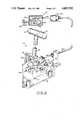
- FIG. 1depicts the brake/shift interlock of one embodiment of the invention in combination with a shift control mechanism for an automatic transmission, and shown in the locked Park position;
- FIG. 2depicts the brake/shift interlock and shift control mechanism of FIG. 1, and shown in the unlocked Park position;
- FIG. 3depicts the brake/shift interlock and shift control mechanism of FIGS. 1 and 2, and shown in a non-Park position;
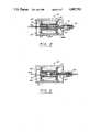
- FIG. 4depicts a solenoid particularly suited for use in the brake/shift interlock of FIGS. 1-3, including a cable extending therethrough and being shown in the energized state;
- FIG. 5shows the solenoid and cable combination of FIG. 4 with the solenoid in its de-energized state
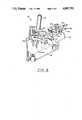
- FIG. 6depicts a second embodiment of the brake/shift interlock in combination with the shift control mechanism, and showing the locked Park position of FIG. 1;
- FIG. 7shows the brake/shift interlock embodiment of FIG. 6 with the control shift mechanism depicted in a non-Park position as in FIG. 3;
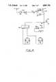
- FIG. 8is a generalized circuit diagram of the brake light power circuit which includes the ignition switch, various brake lights, the brake switch, and further showing the brake/shift interlock solenoid included therein in accordance with the invention.
- a shift control mechanismfor an automatic transmission (not shown).
- the shift control mechanism 10, or simply shift control 10is depicted as being of the type which is floor mounted in the vehicle (not shown), though it will be appreciated that the following disclosed principles of the invention would be similarly applicable to a shift control mounted elsewhere in the vehicle, as for instance on the steering column.
- the shift control 10 depicted in the figures hereinis of a particular type typically found in vehicles manufactured by Ford Motor Company, it will be appreciated that the brake/shift interlock of the invention is similarly applicable to shift controls of other similar, but not identical, construction, as for instance disclosed in the aforementioned U.S. Pat. No. 4,473,141 and U.S. Pat. No. 4,474,085.
- Resortmay be made to the disclosures of those aforementioned patents for a more complete understanding of various shift control mechanisms as they relate in common to the present invention but are not described in detail herein.
- Shift control 10includes a shift lever 12 secured to a bracket or yoke 14 which is pivotally mounted on a base member 16 in a conventional manner (not shown) for movement about a respective pivot axis.
- the base member 16is secured to a body member such as a floor pan (not shown) by a plurality of fasteners (not shown) installed through respective mounting bosses 17.
- the shift lever 12has secured to the upper end thereof a handgrip member 18 which includes a pushbutton 20 disposed therein.
- the pushbutton 20is connected through a push rod 22 to a detent mechanism generally designated 24.
- the detent mechanism 24includes a latch 26 and a latch plate 28.
- the detent latch plate 28is secured to the base member 16 and includes an interior cutout or open portion, the upper end of which defines various detent notches respectively designated P (Park), R (Reverse), N (Neutral), D (Drive), etc.
- the latch 26takes the form of a lever which is pivoted at its inner end at a pivot axis 29 formed near an inner wall of the yoke 14.
- the lever of latch 26extends from axis 29 outward through a vertical slot 30 formed in the opposite wall of the yoke 14 for generally vertical reciprocation into and out of detenting engagement with the detent notches P, R, N, D, etc.
- a spring 32is connected between the yoke 14 and the latch 26 for biasing the latch in an upward direction. Since the push rod 22 extends between pushbutton 20 and the upper surface of latch 26 between its pivot 29 and its outer end, the bias force of spring 32 similarly acts to bias pushbutton 20 and the connecting rod 22 into their non-actuated positions shown in FIG. 1.
- the bias force of spring 32is relatively modest.
- a relatively light manual inward force of approximately six pounds on pushbutton 20is operative to urge the push rod 22 downward, thereby pivoting the outer end of latch 26 downward in its slot 30.
- Such downward actuation of latch 26is required to permit the shift lever 12 to be pivoted from the Park position to one of the other positions P, R, N, D, etc.
- a P/L cam or member 34which operates in conjunction with the key lock cylinder 36 associated with ignition switch 36A (depicted in FIG. 8) and an associated ignition lock mechanism 38 to lock the latch 26 into the Park detent notch in yoke 14 under certain circumstances, and thereby lock the shift lever 12 and the entire shift control mechanism in that position.
- the P/L member 34 in the illustrated embodimentis mounted for pivotal movement about a pivot axis 35, as represented by a journal pin or rivet in the illustrated embodiment.
- the pivot axis 35is fixed with respect to the base member 16 and is conveniently supported either directly or indirectly by the base member 16.
- the P/L member 34may take the very general shape of a bell-crank having one upstanding arm 37 adapted to receive an actuating force and a second arm 39 adapted to engage the underside of the outer end of latch 26 for urging the latch upwardly into a locked position within the Park detent notch.
- the P/L member 34includes an arcuate slot 40 extending for much of the length of its arm 39 to provide a camming surface.
- a camming pin 42is in fixed engagement with the sidewall of the yoke 14 of shift lever 12 and extends outward through the camming slot 40.
- the positioning of the camming pin 42 and the contour of the camming slot 40are such that, as the shift lever 12 is pivoted between the various operating positions, the arm 39 of the P/L member 34 is either caused to pivot away from locking engagement with latch 26 or conversely, is permitted to be drawn upward via arm 37 for such locking engagement.
- the P/L member 34may be actuated into locking engagement with the latch 26 by means of a connecting cable 44 connected in tension between the P/L arm 37 and the ignition lock mechanism 38.
- Cable 44is typically a flexible wire which is slidingly housed in a surrounding protective jacket 45.
- the jacket 45is fixedly positioned at its end closest to P/L arm 37 by being clamped to support bracket 43 by clamping bracket 49.
- the support bracketis rigidly affixed to, and may be an integral part of, base 16.
- P/L arm 37may include a slot 46 extending in from one edge and into which the cable 44 is placed. A head 47 on the end of the cable 44 serves to transmit a tensile force on the cable to the arm 37 and further resists dislodgement of the cable from the slot 46.
- the ignition lock mechanism 38 associated with key lock cylinder 36is depicted in a generalized diagrammatic form herein.
- the key lock cylinder 36is in toothed engagement with a rack 48 connected to a slide 50.
- the slide 50is caused to reciprocate rightward on support 52.
- Such actuation of slide 52serves also to close the contacts of the ignition switch 36A, seen in FIG. 8.
- the ignition lock mechanism 38further includes a bellcrank type lock member 53 pivotally mounted on pivot axis 54 and biased by spring 56 to a withdrawn or retracted position depicted in FIG. 1.
- spring 56is depicted for simplicity as a tension spring, it might be a torsion spring or the like.
- the geometry and positioning of the lock 53 and slide 50are such that, assuming the key lock cylinder 36 is Off, the lock member 53 will be blocked from clockwise rotation. Accordingly, the cable 44, which is connected at its upper end to the other crank leg of lock member 53, is also retained in a withdrawn and locked position.
- a notch 58is provided in the upper surface of slide 50 and is of such depth and positioning that when key lock cylinder 36 is rotated clockwise to the On position depicted in FIG.
- the slide 50moves rightward and brings notch 58 in alignment with the end of lock member 53, thereby allowing clockwise rotation of the lever against its biasing spring 56 in the event a superior tensioning force is applied to the downstream end of the cable 44.
- Such superior forcemay be applied by the latch lever 26 in response to manual actuation of pushbutton 20 which requires a force of about ten pounds to overcome the bias of springs 32 and 56. That situation is depicted in FIG. 2.
- the present inventionfurther provides a brake/shift interlock which is capable of continuing to maintain the shift control mechanism 10 in the Park position even when the key lock cylinder 36 is in the Run position commensurate with the engine running, and may be released principally only when a brake pedal is actuated to apply the vehicle's brakes.
- the present inventionprovides secondary or failure-mode means for releasing the P/L member 34 even in the event that actuation of the vehicle's brakes does not result in the normal and desired response.
- the brake/shift interlockis provided by an electromagnetic actuator, such as solenoid 60, operating through a connecting means such as the cable 44 to either lock or relatively release the P/L member 34 when shift level 12 is in the Park position.
- the solenoid 60includes an armature or plunger 62 which engages the cable 44 in a manner resulting in the cable and the plunger moving in unison relative to the solenoid.
- the solenoid 60is mounted in a fixed position within the vehicle, as represented by the bracket 61 in FIG. 1.
- the solenoid 60includes a generally tubular housing 64 in which is fixedly positioned a bobbin assembly 65 comprised of a central bobbin 66 on which is wound a conventional multiturn electrical coil 67.
- the bobbin assembly 65is typically further housed within a flux-conducting container comprised of a can 68A and an end cap 68B.
- the bobbin 66, the flux container 68A and 68B and the housing 64include a coaxial central opening extending therethrough.
- a tubular electromagnetic stop member 69is inserted and fixed in one end of the bobbin, as by press-fitted and/or bonded engagement therewith.
- the plunger 62is tubular, having a hollow core extending axially therethrough and is sized to reciprocate within the bobbin 66 at the end opposite that in which the stop member 69 is positioned.
- Plunger 62has a radial step in its outside diameter relatively toward its axially outer end to form an outward-facing shoulder or stop surface 70.
- the diameter of the opening 72 in solenoid housing 64is sized to receive and clear only the smaller diameter end of plunger 62 such that the housing end wall limits outward travel of the plunger by engagement with the plunger stop surface 70 as depicted in FIG. 5.
- the axial passage through stop member 69is of sufficient diameter to clear the cable 44.
- the axial passage or opening through plunger 62may be sufficiently large to allow relative threading of cable 44 through the plunger during manufacture and assembly, however the plunger and the cable are then placed in fixed engagement with one another as by radially crimping the radially-reduced diameter of the plunger. In this way the plunger 62 grippingly engages cable 44 such that the two elements move in unison relative to housing 64 of solenoid 60.
- FIG. 4depicts solenoid 60 in its energized state in which plunger 62 is drawn axially inward
- FIG. 5depicts the solenoid in its de-energized state. Assuming the application of some external biasing force as will be explained hereinafter in greater detail, the plunger 62 may then move relatively outward to the position depicted in FIG. 5.
- FIG. 8there is depicted a generalized schematic diagram of the power circuit into which the ends 67A and 67B of coil 67 of solenoid 60 are connected.
- Battery voltage of 12-14 volts(V batt )is applied to an input terminal of ignition switch 36A.
- the output terminal of ignition switch 36Aextends through a fuse 75 and a steering diode 76 to one terminal 67A of the coil of solenoid 60.
- V battis applied to terminal 67 of solenoid 60.
- the other terminal 67B of solenoid 60is connected to a junction 78 to which is also connected one terminal of a brake lamp 80 having its other terminal connected to ground.
- Stop lamp 80may be the conventional high level stop lamp on present day cars.
- left and right stop lamps 84 and 85respectively may also have one terminal connected to junction 78 and the opposite terminal connected to ground.
- Left and right stop lamps 84 and 85may be connected to junction 78 through a multifunction switch block 86 of conventional design which may additionally provide the well known turn signaling and hazard signaling functions.
- a suppression diode 87spans the terminal 67A, 67B of the coil of solenoid 60.
- the brake switch 82is of the type conventionally found in automobiles for closing an electrical circuit between and the various stops lamps 80, 84 and 85 when the operator depresses the brake pedal to actuate the brakes.
- V batt potentialis placed on the brake light circuit at junction 78, which thus also places that same potential on terminal 67B of the solenoid 60. Since substantially the same potential, V batt , then appears on both terminals 67A and 67B of the solenoid 60, the solenoid will be de-energized, thereby releasing the plunger 62 and allowing normal shift operation as depicted in FIG. 2.
- camming pin 42With respect to the camming slot 40 is such as to hold the P/L arm 34 out of locking engagement with the latch 26.
- Camming pin 42holds P/L member 34 in position, despite solenoid 60 being substantially continuously energized and applying a clockwise torque to member 34 via its connection through cable 44 to arm 37.
- solenoid 60will be de-energized each time the brake is depressed and brake switch 82 is closed, it will only operate to lock the shift control mechanism 10 in position if the shift lever 12 is in the Park position. Moreover, no noticeable noise resulting from actuation and de-actuation of the solenoid 60 will be heard in any position of the shift control mechanism 10.
- FIGS. 6 and 7Attention is now directed to an alternate embodiment of the brake/shift interlock as depicted in FIGS. 6 and 7.
- the embodiment of FIGS. 1-3which employed the solenoid construction of FIGS. 4 and 5, depicted the ignition lock mechanism and the brake/shift interlock as being arranged mechanically in series.
- the embodiment of FIGS. 6 and 7depicts those two locking functions as being arranged mechanically in parallel.
- the arm 137 of P/L member 134is depicted as being widened and having a pair of slots 46 and 146 for respectively receiving flexible cables 44 and 144, though the single slot 46 of P/L member might have been used for both cables.
- Cable 144is slidingly housed in jacket 45 and is connected to the conventional ignition lock mechanism 38 depicted in FIG. 1, however the solenoid is completely omitted from that mechanical link between the ignition lock mechanism and the P/L member 134.
- a solenoid 160is mounted to a support bracket 143 by means of a clamping bracket 149 which also supports the end of cable jacket 45.
- the solenoid 160may be identical to solenoid 60 of FIGS. 4 and 5, but typically is of a more standard configuration in which the plunger (not shown) need not be hollow and simply includes means for connecting the flexible cable 144 to the outermost end thereof. Otherwise, the solenoid 160 is connected in the brake light power circuit in the same manner as previously depicted and discussed with respect to FIG. 8. It may be advantageous to provide a return spring associated with the plunger of solenoid 160.
Landscapes
- Engineering & Computer Science (AREA)
- General Engineering & Computer Science (AREA)
- Mechanical Engineering (AREA)
- Arrangement Or Mounting Of Control Devices For Change-Speed Gearing (AREA)
- Control Of Transmission Device (AREA)
Abstract
Description
Claims (18)
Priority Applications (7)
| Application Number | Priority Date | Filing Date | Title |
|---|---|---|---|
| US07/206,255US4887702A (en) | 1988-06-13 | 1988-06-13 | Brake/shift interlock for an automatic transmission shift control mechanism |
| EP89305932AEP0347150B1 (en) | 1988-06-13 | 1989-06-13 | A brake/shift interlock for an automatic transmission shift control mechanism |
| ES89305932TES2049321T3 (en) | 1988-06-13 | 1989-06-13 | BRAKE / SHIFT INTERLOCK FOR A TRANSMISSION SHIFT CONTROL MECHANISM. |
| DE68911763TDE68911763T2 (en) | 1988-06-13 | 1989-06-13 | Brake / shift lock for a shift control arrangement of an automatic vehicle transmission. |
| US07/440,554US5027929A (en) | 1988-06-13 | 1989-11-20 | Solenoid system for, for example, a brake/shift interlock for vehicular transmission control |
| US07/614,415US5078242A (en) | 1988-06-13 | 1990-12-24 | Solenoid system for, for example, a brake/shift interlock for vehicular transmission control |
| US08/178,047USRE35772E (en) | 1988-06-13 | 1994-01-06 | Solenoid system for, for example, a brake/shift interlock for vehicular transmission control |
Applications Claiming Priority (1)
| Application Number | Priority Date | Filing Date | Title |
|---|---|---|---|
| US07/206,255US4887702A (en) | 1988-06-13 | 1988-06-13 | Brake/shift interlock for an automatic transmission shift control mechanism |
Related Child Applications (1)
| Application Number | Title | Priority Date | Filing Date |
|---|---|---|---|
| US07/440,554Continuation-In-PartUS5027929A (en) | 1988-06-13 | 1989-11-20 | Solenoid system for, for example, a brake/shift interlock for vehicular transmission control |
Publications (1)
| Publication Number | Publication Date |
|---|---|
| US4887702Atrue US4887702A (en) | 1989-12-19 |
Family
ID=22765597
Family Applications (1)
| Application Number | Title | Priority Date | Filing Date |
|---|---|---|---|
| US07/206,255Expired - LifetimeUS4887702A (en) | 1988-06-13 | 1988-06-13 | Brake/shift interlock for an automatic transmission shift control mechanism |
Country Status (4)
| Country | Link |
|---|---|
| US (1) | US4887702A (en) |
| EP (1) | EP0347150B1 (en) |
| DE (1) | DE68911763T2 (en) |
| ES (1) | ES2049321T3 (en) |
Cited By (51)
| Publication number | Priority date | Publication date | Assignee | Title |
|---|---|---|---|---|
| WO1990009904A1 (en)* | 1989-02-23 | 1990-09-07 | Sparton Corporation | Service brake and shift lever interlock system |
| US4976171A (en)* | 1989-10-10 | 1990-12-11 | General Motors Corporation | Transmission shifter to operator controlled mechanism interlock |
| US5009295A (en)* | 1989-12-08 | 1991-04-23 | General Motors Corporation | Transmission shifter to operator controlled mechanism interlock |
| US5014831A (en)* | 1988-12-16 | 1991-05-14 | Daimler-Benz Ag | Device for locking an actuating lever of a shifting device |
| US5027929A (en)* | 1988-06-13 | 1991-07-02 | United Technologies Automotive, Inc. | Solenoid system for, for example, a brake/shift interlock for vehicular transmission control |
| US5035156A (en)* | 1989-11-06 | 1991-07-30 | Ford Motor Company | Ignition key-brake switch interlock for a transmission gear selector |
| US5036962A (en)* | 1988-12-27 | 1991-08-06 | Fuji Jukogyo Kabushiki Kaisha | Shift lock system for an automatic transmission of a motor vehicle |
| US5058462A (en)* | 1990-01-22 | 1991-10-22 | Teleflex Incorporated | Parklock cable lock box |
| US5076114A (en)* | 1990-05-14 | 1991-12-31 | Pontiac Coil Inc. | Electromagnetic interlock |
| US5078242A (en)* | 1988-06-13 | 1992-01-07 | United Technologies Automotive, Inc. | Solenoid system for, for example, a brake/shift interlock for vehicular transmission control |
| US5080208A (en)* | 1988-12-22 | 1992-01-14 | Kabushiki Kaisha Tokai-Rika-Denki-Seisakusho | Shift lever apparatus for automatic transmission of vehicle |
| US5096033A (en)* | 1991-01-17 | 1992-03-17 | Grand Haven Stamped Products Company | Lockout mechanism and system for vehicle shifter |
| US5129494A (en)* | 1989-02-23 | 1992-07-14 | Sparton Corporation | Service brake and shift lever interlock system |
| US5150593A (en)* | 1988-03-04 | 1992-09-29 | Honda Giken Kogyo Kabushiki Kaisha | Shift lever device for automatic transmission |
| US5167308A (en)* | 1991-01-17 | 1992-12-01 | Grand Haven Stamped Products, Div. Of Jsj Corporation | Combination brake/park lockout and steering mechanism and system |
| US5180959A (en)* | 1991-08-08 | 1993-01-19 | Eaton Corporation | Electrically controlled shift actuator |
| US5181592A (en)* | 1990-06-11 | 1993-01-26 | Sparton Corporation | Shift lever interlock system |
| US5197356A (en)* | 1991-03-29 | 1993-03-30 | Nissan Motor Co., Ltd. | Vehicle ignition lock and transmission shift lock control mechanism |
| US5211271A (en)* | 1991-01-17 | 1993-05-18 | Grand Haven Stamped Products Company, Div. Of Jsj Corp. | Lockout mechanism and system for vehicle shifter |
| US5220984A (en)* | 1992-04-20 | 1993-06-22 | Grand Haven Stamped Products Company, (Div. Of Jsj Corporation) | Shift mechanism |
| US5251723A (en)* | 1989-02-23 | 1993-10-12 | Sparton Corporation | Service brake and shift lever interlock system |
| US5275065A (en)* | 1992-10-02 | 1994-01-04 | Grand Haven Stamped Products, Div. Of Jsj Corporation | Vehicle transmission shifter with park lock controlled by magnetic latch |
| US5379871A (en)* | 1992-07-28 | 1995-01-10 | Fujikiko Kabushiki Kaisha | Shift lever apparatus |
| US5428977A (en)* | 1992-07-30 | 1995-07-04 | Dr. Ing. H.C.F. Porsche Ag | Arrangement for locking the ignition key of a motor vehicle by the selector lever of an automatic transmission |
| US5489246A (en)* | 1994-08-29 | 1996-02-06 | Pontiac Coil, Inc. | Electronic park lock |
| US5522277A (en)* | 1995-06-12 | 1996-06-04 | Carter Automotive Company, Inc. | Electrically-operated latch |
| US5647818A (en)* | 1995-03-27 | 1997-07-15 | Pontiac Coil, Inc. | Shifter interlock for an automatic transmission |
| US5842364A (en)* | 1996-06-21 | 1998-12-01 | Oliver; Richard D. | Vehicle immobilizing system |
| US5862899A (en)* | 1997-03-10 | 1999-01-26 | Ut Automotive Dearborn, Inc. | Brake-shift interlock |
| US5878626A (en)* | 1995-12-06 | 1999-03-09 | Kuster & Co. Gmbh | Compensation device for a cable-operated brake system |
| US5938562A (en)* | 1998-02-17 | 1999-08-17 | Pontiac Coil, Inc. | Brake shifter interlock with improved park lock switch |
| US5969431A (en)* | 1997-10-08 | 1999-10-19 | Lear Automotive Dearborn, Inc. | Linearly actuating multi-functional apparatus for use in an automotive vehicle |
| US5996763A (en)* | 1997-07-01 | 1999-12-07 | Chuo Hatsujo Kabushiki Kaisha | Gear shift lock device for a vehicular automatic transmission |
| US6059687A (en)* | 1996-01-19 | 2000-05-09 | Automobiles Peugeot | Automotive vehicle incorporating a transmission equipped with an actuating logic performing the "shift-lock" and "key-lock" functions |
| US6142282A (en)* | 1999-01-11 | 2000-11-07 | Pontiac Coil, Inc. | Brake-transmission shift interlock device for an automatic transmission system |
| US6241068B1 (en) | 1999-11-15 | 2001-06-05 | Teleflex Incorporated | Shift lever assembly with a pre-load releasable interlock |
| US6308813B1 (en)* | 2000-09-20 | 2001-10-30 | Lord Corporation | Fluid controlled interlock mechanism and method |
| EP1207321A2 (en) | 2000-11-16 | 2002-05-22 | Saia-Burgess Inc. | Locking apparatus for shift lever |
| US6676564B2 (en) | 2002-01-18 | 2004-01-13 | Saia-Burgess Inc. | Brake-shift lever interlock unit |
| US20040163876A1 (en)* | 2003-02-26 | 2004-08-26 | Mtd Products Inc: | Shift interlock mechanism |
| US20050236252A1 (en)* | 2004-04-23 | 2005-10-27 | Vermeersch Michael C | Integrated position switch/brake transmission shift interlock for electronic gear indication |
| US20060236805A1 (en)* | 2005-04-26 | 2006-10-26 | Ruhlander Gregory P | Gear driven parklock assembly with terminal snap-fit housing |
| US20080093194A1 (en)* | 2006-10-24 | 2008-04-24 | Vermeersch Michael C | Brake-transmission shift interlock assembly |
| US20080234908A1 (en)* | 2007-03-07 | 2008-09-25 | St Clair Kenneth A | Operator input device for controlling a vehicle operation |
| US20090069152A1 (en)* | 2007-09-12 | 2009-03-12 | Vermeersch Michael C | Ignition and transmission shift lever interlock system |
| US20100156582A1 (en)* | 2008-12-01 | 2010-06-24 | Johnson Electric S.A. | Park lock solenoid |
| CN103148215A (en)* | 2011-12-07 | 2013-06-12 | 株式会社东海理化电机制作所 | Solenoid and shift device |
| US20140375401A1 (en)* | 2013-06-24 | 2014-12-25 | Sl Corporation | Solenoid apparatus for shift lever |
| US9019053B1 (en)* | 2013-12-09 | 2015-04-28 | Raymond Contreras | Multi-position magnetic rotary switch |
| US11506277B2 (en)* | 2019-03-25 | 2022-11-22 | Hyundai Motor Company | Anti-theft device for vehicle |
| US11808347B2 (en) | 2021-08-31 | 2023-11-07 | Deere & Company | Automatic park lock |
Families Citing this family (9)
| Publication number | Priority date | Publication date | Assignee | Title |
|---|---|---|---|---|
| US5027931A (en)* | 1990-01-18 | 1991-07-02 | United Technologies Automotive, Inc. | Brake/shift interlock for an automatic transmission shift control mechanism |
| JPH0417557U (en)* | 1990-05-31 | 1992-02-13 | ||
| DE4120379A1 (en)* | 1991-06-20 | 1993-01-07 | Porsche Ag | LOCKING DEVICE FOR A SELECTOR LEVER OF AN AUTOMATIC MOTOR VEHICLE TRANSMISSION |
| US5402870A (en)* | 1993-05-18 | 1995-04-04 | Grand Haven Stamped Products, Div. Of Jsj Corporation | Vehicle park/lock mechanism |
| US5494141A (en)* | 1993-05-18 | 1996-02-27 | Grand Haven Stamped Products, Div. Of Jsj Corporation | Vehicle park/lock mechanism |
| US5677658A (en)* | 1993-05-18 | 1997-10-14 | Grand Haven Stamped Products, Div. Of Jsj Corp. | Electrically operated control module for a locking mechanism |
| US5718312A (en)* | 1993-05-18 | 1998-02-17 | Grand Haven Stamped Products, Div. Of Jsj Corporation | Vehicle park/lock mechanism with control module having a locking mechanism and a control switch actuated by the locking mechanism |
| US5759132A (en)* | 1994-10-27 | 1998-06-02 | Grand Haven Stamped Products, Div. Of Jsj Corp. | Vehicle park/lock mechanism with control module having a locking mechanism and a control switch actuated by the locking mechanism |
| CA2180863A1 (en)* | 1995-08-03 | 1997-02-04 | Charles Osborn | Vehicle shifter |
Citations (15)
| Publication number | Priority date | Publication date | Assignee | Title |
|---|---|---|---|---|
| US2102761A (en)* | 1931-10-12 | 1937-12-21 | Karl Strobel Corp | Welding generator |
| US2437406A (en)* | 1947-01-02 | 1948-03-09 | Draper Corp | Loom stop motion |
| US3629747A (en)* | 1970-03-26 | 1971-12-21 | Westinghouse Electric Corp | Electromagnetic trip device for circuit interrupters |
| DE2139510A1 (en)* | 1971-08-06 | 1973-02-15 | Magnetschultz Spezialfabrik Fu | COIL FOR ELECTROMAGNETS |
| US3942614A (en)* | 1974-06-24 | 1976-03-09 | Thompson Owen L | Gear selector safety lock |
| US4096930A (en)* | 1977-08-05 | 1978-06-27 | Frank Viscardi | Gear shift selector brake interlock |
| US4097833A (en)* | 1976-02-09 | 1978-06-27 | Ledex, Inc. | Electromagnetic actuator |
| JPS5563809A (en)* | 1978-11-08 | 1980-05-14 | Sanmei Denki Kk | Electromagnet |
| JPS5670613A (en)* | 1979-11-15 | 1981-06-12 | Matsushita Electric Works Ltd | Electromagnetic output device |
| GB2104730A (en)* | 1981-08-21 | 1983-03-09 | Hitachi Metals Ltd | Electromagnetic actuator |
| US4473141A (en)* | 1981-03-10 | 1984-09-25 | Nissan Motor Company, Limited | Shift lever and parking brake control |
| US4474085A (en)* | 1982-09-13 | 1984-10-02 | General Motors Corporation | Transmission floor shifter control with a park/lock mechanism |
| US4513276A (en)* | 1981-02-09 | 1985-04-23 | Nissan Motor Company, Limited | Safety system of automotive automatic transmission operating device |
| US4532824A (en)* | 1982-01-06 | 1985-08-06 | Regie Nationale Des Usines Renault | Automobile automatic transmission control device |
| US4660443A (en)* | 1986-01-31 | 1987-04-28 | General Motors Corporation | Transmission selector lever assembly |
Family Cites Families (3)
| Publication number | Priority date | Publication date | Assignee | Title |
|---|---|---|---|---|
| US4187935A (en)* | 1978-02-28 | 1980-02-12 | Hern Thomas R O | Brake operated shift lock |
| DE2843161A1 (en)* | 1978-10-04 | 1980-04-24 | Massey Ferguson Hanomag Inc & | DRIVE DRIVE, ESPECIALLY FOR HEAVY CONSTRUCTION MACHINES, EXCAVATORS OR THE LIKE |
| DE3617256A1 (en)* | 1986-05-22 | 1987-11-26 | Audi Ag | DEVICE ON A MOTOR VEHICLE |
- 1988
- 1988-06-13USUS07/206,255patent/US4887702A/ennot_activeExpired - Lifetime
- 1989
- 1989-06-13ESES89305932Tpatent/ES2049321T3/ennot_activeExpired - Lifetime
- 1989-06-13EPEP89305932Apatent/EP0347150B1/ennot_activeExpired - Lifetime
- 1989-06-13DEDE68911763Tpatent/DE68911763T2/ennot_activeExpired - Lifetime
Patent Citations (15)
| Publication number | Priority date | Publication date | Assignee | Title |
|---|---|---|---|---|
| US2102761A (en)* | 1931-10-12 | 1937-12-21 | Karl Strobel Corp | Welding generator |
| US2437406A (en)* | 1947-01-02 | 1948-03-09 | Draper Corp | Loom stop motion |
| US3629747A (en)* | 1970-03-26 | 1971-12-21 | Westinghouse Electric Corp | Electromagnetic trip device for circuit interrupters |
| DE2139510A1 (en)* | 1971-08-06 | 1973-02-15 | Magnetschultz Spezialfabrik Fu | COIL FOR ELECTROMAGNETS |
| US3942614A (en)* | 1974-06-24 | 1976-03-09 | Thompson Owen L | Gear selector safety lock |
| US4097833A (en)* | 1976-02-09 | 1978-06-27 | Ledex, Inc. | Electromagnetic actuator |
| US4096930A (en)* | 1977-08-05 | 1978-06-27 | Frank Viscardi | Gear shift selector brake interlock |
| JPS5563809A (en)* | 1978-11-08 | 1980-05-14 | Sanmei Denki Kk | Electromagnet |
| JPS5670613A (en)* | 1979-11-15 | 1981-06-12 | Matsushita Electric Works Ltd | Electromagnetic output device |
| US4513276A (en)* | 1981-02-09 | 1985-04-23 | Nissan Motor Company, Limited | Safety system of automotive automatic transmission operating device |
| US4473141A (en)* | 1981-03-10 | 1984-09-25 | Nissan Motor Company, Limited | Shift lever and parking brake control |
| GB2104730A (en)* | 1981-08-21 | 1983-03-09 | Hitachi Metals Ltd | Electromagnetic actuator |
| US4532824A (en)* | 1982-01-06 | 1985-08-06 | Regie Nationale Des Usines Renault | Automobile automatic transmission control device |
| US4474085A (en)* | 1982-09-13 | 1984-10-02 | General Motors Corporation | Transmission floor shifter control with a park/lock mechanism |
| US4660443A (en)* | 1986-01-31 | 1987-04-28 | General Motors Corporation | Transmission selector lever assembly |
Cited By (67)
| Publication number | Priority date | Publication date | Assignee | Title |
|---|---|---|---|---|
| US5150593A (en)* | 1988-03-04 | 1992-09-29 | Honda Giken Kogyo Kabushiki Kaisha | Shift lever device for automatic transmission |
| US5078242A (en)* | 1988-06-13 | 1992-01-07 | United Technologies Automotive, Inc. | Solenoid system for, for example, a brake/shift interlock for vehicular transmission control |
| USRE35772E (en)* | 1988-06-13 | 1998-04-21 | United Technologies Automotive, Inc. | Solenoid system for, for example, a brake/shift interlock for vehicular transmission control |
| US5027929A (en)* | 1988-06-13 | 1991-07-02 | United Technologies Automotive, Inc. | Solenoid system for, for example, a brake/shift interlock for vehicular transmission control |
| US5014831A (en)* | 1988-12-16 | 1991-05-14 | Daimler-Benz Ag | Device for locking an actuating lever of a shifting device |
| US5080208A (en)* | 1988-12-22 | 1992-01-14 | Kabushiki Kaisha Tokai-Rika-Denki-Seisakusho | Shift lever apparatus for automatic transmission of vehicle |
| US5036962A (en)* | 1988-12-27 | 1991-08-06 | Fuji Jukogyo Kabushiki Kaisha | Shift lock system for an automatic transmission of a motor vehicle |
| US5018610A (en)* | 1989-02-23 | 1991-05-28 | Sparton Corporation | Service brake and shift lever interlock system |
| WO1990009904A1 (en)* | 1989-02-23 | 1990-09-07 | Sparton Corporation | Service brake and shift lever interlock system |
| US5129494A (en)* | 1989-02-23 | 1992-07-14 | Sparton Corporation | Service brake and shift lever interlock system |
| US5251723A (en)* | 1989-02-23 | 1993-10-12 | Sparton Corporation | Service brake and shift lever interlock system |
| US4976171A (en)* | 1989-10-10 | 1990-12-11 | General Motors Corporation | Transmission shifter to operator controlled mechanism interlock |
| US5035156A (en)* | 1989-11-06 | 1991-07-30 | Ford Motor Company | Ignition key-brake switch interlock for a transmission gear selector |
| US5009295A (en)* | 1989-12-08 | 1991-04-23 | General Motors Corporation | Transmission shifter to operator controlled mechanism interlock |
| US5058462A (en)* | 1990-01-22 | 1991-10-22 | Teleflex Incorporated | Parklock cable lock box |
| US5076114A (en)* | 1990-05-14 | 1991-12-31 | Pontiac Coil Inc. | Electromagnetic interlock |
| US5181592A (en)* | 1990-06-11 | 1993-01-26 | Sparton Corporation | Shift lever interlock system |
| US5096033A (en)* | 1991-01-17 | 1992-03-17 | Grand Haven Stamped Products Company | Lockout mechanism and system for vehicle shifter |
| US5211271A (en)* | 1991-01-17 | 1993-05-18 | Grand Haven Stamped Products Company, Div. Of Jsj Corp. | Lockout mechanism and system for vehicle shifter |
| US5167308A (en)* | 1991-01-17 | 1992-12-01 | Grand Haven Stamped Products, Div. Of Jsj Corporation | Combination brake/park lockout and steering mechanism and system |
| US5197356A (en)* | 1991-03-29 | 1993-03-30 | Nissan Motor Co., Ltd. | Vehicle ignition lock and transmission shift lock control mechanism |
| US5180959A (en)* | 1991-08-08 | 1993-01-19 | Eaton Corporation | Electrically controlled shift actuator |
| US5220984A (en)* | 1992-04-20 | 1993-06-22 | Grand Haven Stamped Products Company, (Div. Of Jsj Corporation) | Shift mechanism |
| US5379871A (en)* | 1992-07-28 | 1995-01-10 | Fujikiko Kabushiki Kaisha | Shift lever apparatus |
| US5428977A (en)* | 1992-07-30 | 1995-07-04 | Dr. Ing. H.C.F. Porsche Ag | Arrangement for locking the ignition key of a motor vehicle by the selector lever of an automatic transmission |
| US5275065A (en)* | 1992-10-02 | 1994-01-04 | Grand Haven Stamped Products, Div. Of Jsj Corporation | Vehicle transmission shifter with park lock controlled by magnetic latch |
| US5489246A (en)* | 1994-08-29 | 1996-02-06 | Pontiac Coil, Inc. | Electronic park lock |
| US5647818A (en)* | 1995-03-27 | 1997-07-15 | Pontiac Coil, Inc. | Shifter interlock for an automatic transmission |
| US5902209A (en)* | 1995-03-27 | 1999-05-11 | Pontiac Coil, Inc. | Shifter interlock for an automatic transmission |
| US5522277A (en)* | 1995-06-12 | 1996-06-04 | Carter Automotive Company, Inc. | Electrically-operated latch |
| US5878626A (en)* | 1995-12-06 | 1999-03-09 | Kuster & Co. Gmbh | Compensation device for a cable-operated brake system |
| US6059687A (en)* | 1996-01-19 | 2000-05-09 | Automobiles Peugeot | Automotive vehicle incorporating a transmission equipped with an actuating logic performing the "shift-lock" and "key-lock" functions |
| US5842364A (en)* | 1996-06-21 | 1998-12-01 | Oliver; Richard D. | Vehicle immobilizing system |
| US5862899A (en)* | 1997-03-10 | 1999-01-26 | Ut Automotive Dearborn, Inc. | Brake-shift interlock |
| US5996763A (en)* | 1997-07-01 | 1999-12-07 | Chuo Hatsujo Kabushiki Kaisha | Gear shift lock device for a vehicular automatic transmission |
| US5969431A (en)* | 1997-10-08 | 1999-10-19 | Lear Automotive Dearborn, Inc. | Linearly actuating multi-functional apparatus for use in an automotive vehicle |
| US5938562A (en)* | 1998-02-17 | 1999-08-17 | Pontiac Coil, Inc. | Brake shifter interlock with improved park lock switch |
| US6142282A (en)* | 1999-01-11 | 2000-11-07 | Pontiac Coil, Inc. | Brake-transmission shift interlock device for an automatic transmission system |
| US6241068B1 (en) | 1999-11-15 | 2001-06-05 | Teleflex Incorporated | Shift lever assembly with a pre-load releasable interlock |
| US6308813B1 (en)* | 2000-09-20 | 2001-10-30 | Lord Corporation | Fluid controlled interlock mechanism and method |
| WO2002025143A1 (en) | 2000-09-20 | 2002-03-28 | Lord Corporation | Fluid controlled interlock mechanism and method |
| EP1207321A2 (en) | 2000-11-16 | 2002-05-22 | Saia-Burgess Inc. | Locking apparatus for shift lever |
| EP1207321A3 (en)* | 2000-11-16 | 2003-08-13 | Saia-Burgess Inc. | Locking apparatus for shift lever |
| US6676564B2 (en) | 2002-01-18 | 2004-01-13 | Saia-Burgess Inc. | Brake-shift lever interlock unit |
| US20040163876A1 (en)* | 2003-02-26 | 2004-08-26 | Mtd Products Inc: | Shift interlock mechanism |
| US6913104B2 (en) | 2003-02-26 | 2005-07-05 | Mtd Products Inc | Shift interlock mechanism |
| US20050236252A1 (en)* | 2004-04-23 | 2005-10-27 | Vermeersch Michael C | Integrated position switch/brake transmission shift interlock for electronic gear indication |
| US7278526B2 (en) | 2004-04-23 | 2007-10-09 | Delphi Technologies, Inc. | Integrated position switch/brake transmission shift interlock for electronic gear indication |
| US20060236805A1 (en)* | 2005-04-26 | 2006-10-26 | Ruhlander Gregory P | Gear driven parklock assembly with terminal snap-fit housing |
| US7568405B2 (en)* | 2005-04-26 | 2009-08-04 | Dura Global Technologies, Inc. | Gear driven parklock assembly with terminal snap-fit housing |
| US20080093194A1 (en)* | 2006-10-24 | 2008-04-24 | Vermeersch Michael C | Brake-transmission shift interlock assembly |
| US8602194B2 (en)* | 2006-10-24 | 2013-12-10 | Steering Solutions Ip Holding Corporation | Brake-transmission shift interlock assembly |
| US20080234908A1 (en)* | 2007-03-07 | 2008-09-25 | St Clair Kenneth A | Operator input device for controlling a vehicle operation |
| US7749135B2 (en)* | 2007-09-12 | 2010-07-06 | Gm Global Technology Operations, Inc. | Ignition and transmission shift lever interlock system |
| US20090069152A1 (en)* | 2007-09-12 | 2009-03-12 | Vermeersch Michael C | Ignition and transmission shift lever interlock system |
| US20100156582A1 (en)* | 2008-12-01 | 2010-06-24 | Johnson Electric S.A. | Park lock solenoid |
| US8400242B2 (en)* | 2008-12-01 | 2013-03-19 | Johnson Electric S.A. | Park lock solenoid |
| CN101839338B (en)* | 2008-12-01 | 2014-06-25 | 德昌电机(深圳)有限公司 | Solenoid |
| US8729993B2 (en)* | 2011-12-07 | 2014-05-20 | Kabushiki Kaisha Tokai-Rika-Denki-Seisakusho | Solenoid and shift device |
| US20130147585A1 (en)* | 2011-12-07 | 2013-06-13 | Kabushiki Kaisha Tokai-Rika-Denki-Seisakusho | Solenoid and shift device |
| CN103148215A (en)* | 2011-12-07 | 2013-06-12 | 株式会社东海理化电机制作所 | Solenoid and shift device |
| CN103148215B (en)* | 2011-12-07 | 2016-01-06 | 株式会社东海理化电机制作所 | Electromagnetic element and gearshift |
| US20140375401A1 (en)* | 2013-06-24 | 2014-12-25 | Sl Corporation | Solenoid apparatus for shift lever |
| US9384882B2 (en)* | 2013-06-24 | 2016-07-05 | Sl Corporation | Noise reducing solenoid apparatus for shift lever |
| US9019053B1 (en)* | 2013-12-09 | 2015-04-28 | Raymond Contreras | Multi-position magnetic rotary switch |
| US11506277B2 (en)* | 2019-03-25 | 2022-11-22 | Hyundai Motor Company | Anti-theft device for vehicle |
| US11808347B2 (en) | 2021-08-31 | 2023-11-07 | Deere & Company | Automatic park lock |
Also Published As
| Publication number | Publication date |
|---|---|
| DE68911763D1 (en) | 1994-02-10 |
| EP0347150A3 (en) | 1990-08-01 |
| ES2049321T3 (en) | 1994-04-16 |
| EP0347150B1 (en) | 1993-12-29 |
| EP0347150A2 (en) | 1989-12-20 |
| DE68911763T2 (en) | 1994-05-26 |
Similar Documents
| Publication | Publication Date | Title |
|---|---|---|
| US4887702A (en) | Brake/shift interlock for an automatic transmission shift control mechanism | |
| US5027929A (en) | Solenoid system for, for example, a brake/shift interlock for vehicular transmission control | |
| US5078242A (en) | Solenoid system for, for example, a brake/shift interlock for vehicular transmission control | |
| US5489246A (en) | Electronic park lock | |
| US5096033A (en) | Lockout mechanism and system for vehicle shifter | |
| US5167308A (en) | Combination brake/park lockout and steering mechanism and system | |
| US5018610A (en) | Service brake and shift lever interlock system | |
| US5647818A (en) | Shifter interlock for an automatic transmission | |
| US5036962A (en) | Shift lock system for an automatic transmission of a motor vehicle | |
| US5129494A (en) | Service brake and shift lever interlock system | |
| MXPA97001603A (en) | Electron parking insurance | |
| US5211271A (en) | Lockout mechanism and system for vehicle shifter | |
| JPH0137934Y2 (en) | ||
| US5309744A (en) | Locking apparatus for shift lever of automatic transmission | |
| EP0307846B1 (en) | Device for locking shift lever of automatic transmission | |
| US4966262A (en) | Transmission safety locking lever apparatus | |
| US5062509A (en) | Shifter mounted brake-transmission interlock | |
| US5251723A (en) | Service brake and shift lever interlock system | |
| JP3103291B2 (en) | Vehicle lock device | |
| US5025901A (en) | Shift lever apparatus for automatic transmission | |
| EP0939251B1 (en) | Shift-lever devices | |
| US5729187A (en) | Transmission shift interlock | |
| US6175292B1 (en) | Electrical actuator | |
| US5035156A (en) | Ignition key-brake switch interlock for a transmission gear selector | |
| US5133436A (en) | Steering column mounted gear selector mechanism for automatic transmissions having safety lock |
Legal Events
| Date | Code | Title | Description |
|---|---|---|---|
| AS | Assignment | Owner name:UNITED TECHNOLOGIES AUTOMOTIVE, INC., MICHIGAN Free format text:ASSIGNMENT OF ASSIGNORS INTEREST.;ASSIGNORS:RATKE, RICHARD;ELLISON, DONALD E.;REEL/FRAME:005021/0366 Effective date:19880728 | |
| STCF | Information on status: patent grant | Free format text:PATENTED CASE | |
| FEPP | Fee payment procedure | Free format text:PAYOR NUMBER ASSIGNED (ORIGINAL EVENT CODE: ASPN); ENTITY STATUS OF PATENT OWNER: LARGE ENTITY | |
| FPAY | Fee payment | Year of fee payment:4 | |
| FPAY | Fee payment | Year of fee payment:8 | |
| AS | Assignment | Owner name:UT AUTOMOTIVE DEARBORN, INC., MICHIGAN Free format text:ASSIGNMENT OF ASSIGNORS INTEREST;ASSIGNOR:UNITED TECHNOLOGIES AUTOMOTIVE, INC.;REEL/FRAME:008995/0526 Effective date:19980224 | |
| FEPP | Fee payment procedure | Free format text:PAYER NUMBER DE-ASSIGNED (ORIGINAL EVENT CODE: RMPN); ENTITY STATUS OF PATENT OWNER: LARGE ENTITY Free format text:PAYOR NUMBER ASSIGNED (ORIGINAL EVENT CODE: ASPN); ENTITY STATUS OF PATENT OWNER: LARGE ENTITY | |
| FPAY | Fee payment | Year of fee payment:12 | |
| AS | Assignment | Owner name:LEAR AUTOMOTIVE DEARBORN, INC., MICHIGAN Free format text:CHANGE OF NAME;ASSIGNOR:UT AUTOMOTIVE DEARBORN, INC.;REEL/FRAME:014172/0756 Effective date:19990617 | |
| AS | Assignment | Owner name:JPMORGAN CHASE BANK, N.A., AS GENERAL ADMINISTRATI Free format text:SECURITY AGREEMENT;ASSIGNOR:LEAR AUTOMOTIVE DEARBORN, INC.;REEL/FRAME:017823/0950 Effective date:20060425 | |
| AS | Assignment | Owner name:LEAR AUTOMOTIVE DEARBORN, INC., MICHIGAN Free format text:RELEASE BY SECURED PARTY;ASSIGNOR:JPMORGAN CHASE BANK, N.A.;REEL/FRAME:032712/0428 Effective date:20100830 |