US4887438A - Desiccant assisted air conditioner - Google Patents
Desiccant assisted air conditionerDownload PDFInfo
- Publication number
- US4887438A US4887438AUS07/315,592US31559289AUS4887438AUS 4887438 AUS4887438 AUS 4887438AUS 31559289 AUS31559289 AUS 31559289AUS 4887438 AUS4887438 AUS 4887438A
- Authority
- US
- United States
- Prior art keywords
- air
- desiccant
- duct
- dehumidifying
- outside air
- Prior art date
- Legal status (The legal status is an assumption and is not a legal conclusion. Google has not performed a legal analysis and makes no representation as to the accuracy of the status listed.)
- Expired - Lifetime
Links
- 239000002274desiccantSubstances0.000titleclaimsabstractdescription119
- 238000005057refrigerationMethods0.000claimsabstractdescription57
- 238000004378air conditioningMethods0.000claimsabstractdescription24
- 230000001143conditioned effectEffects0.000claimsabstractdescription24
- 230000008929regenerationEffects0.000claimsabstractdescription23
- 238000011069regeneration methodMethods0.000claimsabstractdescription23
- 239000002918waste heatSubstances0.000claimsabstractdescription15
- 238000001816coolingMethods0.000claimsdescription80
- 239000007788liquidSubstances0.000claimsdescription25
- 230000001172regenerating effectEffects0.000claimsdescription21
- 238000012546transferMethods0.000claimsdescription18
- 239000007789gasSubstances0.000claimsdescription16
- 238000007791dehumidificationMethods0.000claimsdescription13
- 239000003507refrigerantSubstances0.000claimsdescription11
- 238000002347injectionMethods0.000claimsdescription8
- 239000007924injectionSubstances0.000claimsdescription8
- 238000010521absorption reactionMethods0.000claimsdescription4
- 238000011144upstream manufacturingMethods0.000claimsdescription4
- 230000001105regulatory effectEffects0.000claims4
- 238000007599dischargingMethods0.000claims2
- 230000003134recirculating effectEffects0.000claims1
- 238000000034methodMethods0.000description11
- 230000008569processEffects0.000description11
- 239000007787solidSubstances0.000description10
- 238000010586diagramMethods0.000description8
- 230000000694effectsEffects0.000description6
- 230000006698inductionEffects0.000description6
- 238000007906compressionMethods0.000description5
- 230000007420reactivationEffects0.000description5
- KWGKDLIKAYFUFQ-UHFFFAOYSA-Mlithium chlorideChemical compound[Li+].[Cl-]KWGKDLIKAYFUFQ-UHFFFAOYSA-M0.000description4
- 238000003303reheatingMethods0.000description4
- 238000007710freezingMethods0.000description3
- 230000008014freezingEffects0.000description3
- VYPSYNLAJGMNEJ-UHFFFAOYSA-NSilicium dioxideChemical compoundO=[Si]=OVYPSYNLAJGMNEJ-UHFFFAOYSA-N0.000description2
- 238000009833condensationMethods0.000description2
- 230000005494condensationEffects0.000description2
- 230000003247decreasing effectEffects0.000description2
- 230000008020evaporationEffects0.000description2
- 238000001704evaporationMethods0.000description2
- 239000000463materialSubstances0.000description2
- 238000011084recoveryMethods0.000description2
- 239000000741silica gelSubstances0.000description2
- 229910002027silica gelInorganic materials0.000description2
- 239000007921spraySubstances0.000description2
- 238000009423ventilationMethods0.000description2
- 239000002699waste materialSubstances0.000description2
- VOPWNXZWBYDODV-UHFFFAOYSA-NChlorodifluoromethaneChemical compoundFC(F)ClVOPWNXZWBYDODV-UHFFFAOYSA-N0.000description1
- 239000006096absorbing agentSubstances0.000description1
- 230000009471actionEffects0.000description1
- 238000013459approachMethods0.000description1
- 230000001580bacterial effectEffects0.000description1
- 230000008901benefitEffects0.000description1
- 230000003749cleanlinessEffects0.000description1
- 230000000052comparative effectEffects0.000description1
- 230000006835compressionEffects0.000description1
- 239000004020conductorSubstances0.000description1
- 239000000356contaminantSubstances0.000description1
- 238000011217control strategyMethods0.000description1
- 230000001351cycling effectEffects0.000description1
- 238000013461designMethods0.000description1
- 230000006866deteriorationEffects0.000description1
- 238000006073displacement reactionMethods0.000description1
- 239000000428dustSubstances0.000description1
- 239000012530fluidSubstances0.000description1
- 230000002538fungal effectEffects0.000description1
- 230000036541healthEffects0.000description1
- 239000011159matrix materialSubstances0.000description1
- 239000000203mixtureSubstances0.000description1
- 230000004048modificationEffects0.000description1
- 238000012986modificationMethods0.000description1
- 230000003071parasitic effectEffects0.000description1
- 239000002245particleSubstances0.000description1
- 238000004064recyclingMethods0.000description1
- 230000004044responseEffects0.000description1
- 150000003839saltsChemical class0.000description1
- 229920006395saturated elastomerPolymers0.000description1
- 239000013589supplementSubstances0.000description1
- 230000000153supplemental effectEffects0.000description1
- 230000003612virological effectEffects0.000description1
- 238000004804windingMethods0.000description1
Images


Classifications
- F—MECHANICAL ENGINEERING; LIGHTING; HEATING; WEAPONS; BLASTING
- F24—HEATING; RANGES; VENTILATING
- F24D—DOMESTIC- OR SPACE-HEATING SYSTEMS, e.g. CENTRAL HEATING SYSTEMS; DOMESTIC HOT-WATER SUPPLY SYSTEMS; ELEMENTS OR COMPONENTS THEREFOR
- F24D5/00—Hot-air central heating systems; Exhaust gas central heating systems
- F24D5/12—Hot-air central heating systems; Exhaust gas central heating systems using heat pumps
- F—MECHANICAL ENGINEERING; LIGHTING; HEATING; WEAPONS; BLASTING
- F24—HEATING; RANGES; VENTILATING
- F24F—AIR-CONDITIONING; AIR-HUMIDIFICATION; VENTILATION; USE OF AIR CURRENTS FOR SCREENING
- F24F3/00—Air-conditioning systems in which conditioned primary air is supplied from one or more central stations to distributing units in the rooms or spaces where it may receive secondary treatment; Apparatus specially designed for such systems
- F24F3/12—Air-conditioning systems in which conditioned primary air is supplied from one or more central stations to distributing units in the rooms or spaces where it may receive secondary treatment; Apparatus specially designed for such systems characterised by the treatment of the air otherwise than by heating and cooling
- F24F3/14—Air-conditioning systems in which conditioned primary air is supplied from one or more central stations to distributing units in the rooms or spaces where it may receive secondary treatment; Apparatus specially designed for such systems characterised by the treatment of the air otherwise than by heating and cooling by humidification; by dehumidification
- F24F3/1411—Air-conditioning systems in which conditioned primary air is supplied from one or more central stations to distributing units in the rooms or spaces where it may receive secondary treatment; Apparatus specially designed for such systems characterised by the treatment of the air otherwise than by heating and cooling by humidification; by dehumidification by absorbing or adsorbing water, e.g. using an hygroscopic desiccant
- F24F3/1417—Air-conditioning systems in which conditioned primary air is supplied from one or more central stations to distributing units in the rooms or spaces where it may receive secondary treatment; Apparatus specially designed for such systems characterised by the treatment of the air otherwise than by heating and cooling by humidification; by dehumidification by absorbing or adsorbing water, e.g. using an hygroscopic desiccant with liquid hygroscopic desiccants
- F—MECHANICAL ENGINEERING; LIGHTING; HEATING; WEAPONS; BLASTING
- F24—HEATING; RANGES; VENTILATING
- F24F—AIR-CONDITIONING; AIR-HUMIDIFICATION; VENTILATION; USE OF AIR CURRENTS FOR SCREENING
- F24F3/00—Air-conditioning systems in which conditioned primary air is supplied from one or more central stations to distributing units in the rooms or spaces where it may receive secondary treatment; Apparatus specially designed for such systems
- F24F3/12—Air-conditioning systems in which conditioned primary air is supplied from one or more central stations to distributing units in the rooms or spaces where it may receive secondary treatment; Apparatus specially designed for such systems characterised by the treatment of the air otherwise than by heating and cooling
- F24F3/14—Air-conditioning systems in which conditioned primary air is supplied from one or more central stations to distributing units in the rooms or spaces where it may receive secondary treatment; Apparatus specially designed for such systems characterised by the treatment of the air otherwise than by heating and cooling by humidification; by dehumidification
- F24F3/1411—Air-conditioning systems in which conditioned primary air is supplied from one or more central stations to distributing units in the rooms or spaces where it may receive secondary treatment; Apparatus specially designed for such systems characterised by the treatment of the air otherwise than by heating and cooling by humidification; by dehumidification by absorbing or adsorbing water, e.g. using an hygroscopic desiccant
- F24F3/1423—Air-conditioning systems in which conditioned primary air is supplied from one or more central stations to distributing units in the rooms or spaces where it may receive secondary treatment; Apparatus specially designed for such systems characterised by the treatment of the air otherwise than by heating and cooling by humidification; by dehumidification by absorbing or adsorbing water, e.g. using an hygroscopic desiccant with a moving bed of solid desiccants, e.g. a rotary wheel supporting solid desiccants
- F—MECHANICAL ENGINEERING; LIGHTING; HEATING; WEAPONS; BLASTING
- F28—HEAT EXCHANGE IN GENERAL
- F28D—HEAT-EXCHANGE APPARATUS, NOT PROVIDED FOR IN ANOTHER SUBCLASS, IN WHICH THE HEAT-EXCHANGE MEDIA DO NOT COME INTO DIRECT CONTACT
- F28D15/00—Heat-exchange apparatus with the intermediate heat-transfer medium in closed tubes passing into or through the conduit walls ; Heat-exchange apparatus employing intermediate heat-transfer medium or bodies
- F28D15/02—Heat-exchange apparatus with the intermediate heat-transfer medium in closed tubes passing into or through the conduit walls ; Heat-exchange apparatus employing intermediate heat-transfer medium or bodies in which the medium condenses and evaporates, e.g. heat pipes
- F—MECHANICAL ENGINEERING; LIGHTING; HEATING; WEAPONS; BLASTING
- F24—HEATING; RANGES; VENTILATING
- F24F—AIR-CONDITIONING; AIR-HUMIDIFICATION; VENTILATION; USE OF AIR CURRENTS FOR SCREENING
- F24F3/00—Air-conditioning systems in which conditioned primary air is supplied from one or more central stations to distributing units in the rooms or spaces where it may receive secondary treatment; Apparatus specially designed for such systems
- F24F3/12—Air-conditioning systems in which conditioned primary air is supplied from one or more central stations to distributing units in the rooms or spaces where it may receive secondary treatment; Apparatus specially designed for such systems characterised by the treatment of the air otherwise than by heating and cooling
- F24F3/14—Air-conditioning systems in which conditioned primary air is supplied from one or more central stations to distributing units in the rooms or spaces where it may receive secondary treatment; Apparatus specially designed for such systems characterised by the treatment of the air otherwise than by heating and cooling by humidification; by dehumidification
- F24F2003/144—Air-conditioning systems in which conditioned primary air is supplied from one or more central stations to distributing units in the rooms or spaces where it may receive secondary treatment; Apparatus specially designed for such systems characterised by the treatment of the air otherwise than by heating and cooling by humidification; by dehumidification by dehumidification only
- F—MECHANICAL ENGINEERING; LIGHTING; HEATING; WEAPONS; BLASTING
- F24—HEATING; RANGES; VENTILATING
- F24F—AIR-CONDITIONING; AIR-HUMIDIFICATION; VENTILATION; USE OF AIR CURRENTS FOR SCREENING
- F24F2203/00—Devices or apparatus used for air treatment
- F24F2203/10—Rotary wheel
- F24F2203/1004—Bearings or driving means
- F—MECHANICAL ENGINEERING; LIGHTING; HEATING; WEAPONS; BLASTING
- F24—HEATING; RANGES; VENTILATING
- F24F—AIR-CONDITIONING; AIR-HUMIDIFICATION; VENTILATION; USE OF AIR CURRENTS FOR SCREENING
- F24F2203/00—Devices or apparatus used for air treatment
- F24F2203/10—Rotary wheel
- F24F2203/1016—Rotary wheel combined with another type of cooling principle, e.g. compression cycle
- F—MECHANICAL ENGINEERING; LIGHTING; HEATING; WEAPONS; BLASTING
- F24—HEATING; RANGES; VENTILATING
- F24F—AIR-CONDITIONING; AIR-HUMIDIFICATION; VENTILATION; USE OF AIR CURRENTS FOR SCREENING
- F24F2203/00—Devices or apparatus used for air treatment
- F24F2203/10—Rotary wheel
- F24F2203/102—Rotary wheel combined with a heat pipe
- F—MECHANICAL ENGINEERING; LIGHTING; HEATING; WEAPONS; BLASTING
- F24—HEATING; RANGES; VENTILATING
- F24F—AIR-CONDITIONING; AIR-HUMIDIFICATION; VENTILATION; USE OF AIR CURRENTS FOR SCREENING
- F24F2203/00—Devices or apparatus used for air treatment
- F24F2203/10—Rotary wheel
- F24F2203/1028—Rotary wheel combined with a spraying device
- F—MECHANICAL ENGINEERING; LIGHTING; HEATING; WEAPONS; BLASTING
- F24—HEATING; RANGES; VENTILATING
- F24F—AIR-CONDITIONING; AIR-HUMIDIFICATION; VENTILATION; USE OF AIR CURRENTS FOR SCREENING
- F24F2203/00—Devices or apparatus used for air treatment
- F24F2203/10—Rotary wheel
- F24F2203/1032—Desiccant wheel
- F—MECHANICAL ENGINEERING; LIGHTING; HEATING; WEAPONS; BLASTING
- F24—HEATING; RANGES; VENTILATING
- F24F—AIR-CONDITIONING; AIR-HUMIDIFICATION; VENTILATION; USE OF AIR CURRENTS FOR SCREENING
- F24F2203/00—Devices or apparatus used for air treatment
- F24F2203/10—Rotary wheel
- F24F2203/1056—Rotary wheel comprising a reheater
- F—MECHANICAL ENGINEERING; LIGHTING; HEATING; WEAPONS; BLASTING
- F24—HEATING; RANGES; VENTILATING
- F24F—AIR-CONDITIONING; AIR-HUMIDIFICATION; VENTILATION; USE OF AIR CURRENTS FOR SCREENING
- F24F2203/00—Devices or apparatus used for air treatment
- F24F2203/10—Rotary wheel
- F24F2203/1068—Rotary wheel comprising one rotor
- F—MECHANICAL ENGINEERING; LIGHTING; HEATING; WEAPONS; BLASTING
- F24—HEATING; RANGES; VENTILATING
- F24F—AIR-CONDITIONING; AIR-HUMIDIFICATION; VENTILATION; USE OF AIR CURRENTS FOR SCREENING
- F24F2203/00—Devices or apparatus used for air treatment
- F24F2203/10—Rotary wheel
- F24F2203/1084—Rotary wheel comprising two flow rotor segments
- Y—GENERAL TAGGING OF NEW TECHNOLOGICAL DEVELOPMENTS; GENERAL TAGGING OF CROSS-SECTIONAL TECHNOLOGIES SPANNING OVER SEVERAL SECTIONS OF THE IPC; TECHNICAL SUBJECTS COVERED BY FORMER USPC CROSS-REFERENCE ART COLLECTIONS [XRACs] AND DIGESTS
- Y02—TECHNOLOGIES OR APPLICATIONS FOR MITIGATION OR ADAPTATION AGAINST CLIMATE CHANGE
- Y02B—CLIMATE CHANGE MITIGATION TECHNOLOGIES RELATED TO BUILDINGS, e.g. HOUSING, HOUSE APPLIANCES OR RELATED END-USER APPLICATIONS
- Y02B30/00—Energy efficient heating, ventilation or air conditioning [HVAC]
- Y02B30/13—Hot air central heating systems using heat pumps
- Y—GENERAL TAGGING OF NEW TECHNOLOGICAL DEVELOPMENTS; GENERAL TAGGING OF CROSS-SECTIONAL TECHNOLOGIES SPANNING OVER SEVERAL SECTIONS OF THE IPC; TECHNICAL SUBJECTS COVERED BY FORMER USPC CROSS-REFERENCE ART COLLECTIONS [XRACs] AND DIGESTS
- Y02—TECHNOLOGIES OR APPLICATIONS FOR MITIGATION OR ADAPTATION AGAINST CLIMATE CHANGE
- Y02P—CLIMATE CHANGE MITIGATION TECHNOLOGIES IN THE PRODUCTION OR PROCESSING OF GOODS
- Y02P80/00—Climate change mitigation technologies for sector-wide applications
- Y02P80/10—Efficient use of energy, e.g. using compressed air or pressurized fluid as energy carrier
- Y02P80/15—On-site combined power, heat or cool generation or distribution, e.g. combined heat and power [CHP] supply
Definitions
- This inventionrelates to an electrically operated system that conditions air to be used in occupied building space so that it is both cooled and dehumidified.
- the optimum temperature range for human comfortis well established while the humidity range is recognized but not universally applied. For example, heretofore a range of 20% to 80% was thought to be permissive, while a more optimum range of 40% to 60% is now shown to be required in order to minimize and/or eliminate bacterial, viral and fungal growth.
- Humidityhas its affect upon air cleanliness, as it reduces the presence of dust particles, and the deterioration of building structure and contents, otherwise subjected to excess moisture. Accordingly, humidity control becomes an important factor as related to both human comfort and health, and to structural longevity as well.
- SASupply air
- SASupply air
- OSAoutside air
- RAreturn air
- SAsupply air
- a feature of this inventionis the desiccant dehumidifier that is regenerated by a column of heated air tempered by waste heat of the refrigeration system, a mechanical system with a condenser coil thereof in the heated air column at the regeneration side of the dehumidifier.
- a solid desiccant or liquid desiccant dehumidifiercan be employed as desired.
- a solid desiccant systemis prefered, of the dynamic type and of rotary bed configuration, wherein the bed is a wheel comprised of a screen of tubes or plates of solid desiccant to which air can be continuously exposed, progressively exposed to a dehumidifying air duct and then to a regeneration air duct.
- the dehumidifyingis from minumum outside air (OSA) to be mixed with return air (RA) and then cooled and discharged as supply air (SA).
- the regeneration air ductis also from outside air (OSA) to be discharged to ambient as exhaust (EXH).
- the greater portion, approximately 2/3 of the rotary bed of desiccantis exposed to the dehumidifying duct, while the lesser portion, approximately 1/3, is exposed to the regenerating air duct.
- the heated air regeneration ductis supplied with outside air (OSA) by means of a blower, and the air heated by a condenser coil, and then discharged to atmosphere (EXH) after regeneration of the desiccant.
- the air ductsare sealed with the rotary bed of desiccant which is rotated slowly by a variable speed motor.
- the relative cooling requirements of the different available desiccantsrelate directly to the amount of regenerating energy employed, because of the carryover of heat by the desiccant and associated structure. This heat, plus the heat of condensation, must be removed by cooling. As a result, relative cooling requirements for the different types of commercially available dehumidifiers represent a significant portion of the regeneration energy requirement.
- the after cooling meansis embodied in several forms.
- the excess discharge of return air (RA)is at a relatively low temperature and of relatively low humidity, coming from the conditioned air space, and is subject to being evaporatively cooled. Accordingly, it is this exhaust air flow which is advantageously utilized to absorb heat from heated air leaving the desiccant dehumidifier; in one embodiment by means of evaporatively cooled air flowing through a heat exchanger; and in one embodiment by means of heat pipes extending between cold side and hot side heat exchangers in the return air exhaust duct and in the desiccant dehumidifier delivery duct.
- the evaporative cooler and/or heat pipestransfer heat energy between the outgoing and incoming air.
- Desuperheatingis used to supply liquid desiccant in the liquid desiccant embodiment herein disclosed, to spray cooler desiccant liquid into the humidifying section thereof.
- the dehumidifying fluid circuitis associated with the refrigeration compressor as will be described.
- This inventioninvolves dehumidification and refrigeration of air, utilizing a desiccant, and preferably a solid desiccant rotary wheel in an electrically operated package air-conditioning or heat pump unit.
- a desiccantand preferably a solid desiccant rotary wheel in an electrically operated package air-conditioning or heat pump unit.
- net savingsare realized so as to recover any additional investment costs.
- the combined components of a vapor-compression system with a desiccant system, a hybrid systemefficiently removes the sensible and latent cooling loads, a general object of this invention.
- the vapor-compression machineoperates with higher evaporator temperatures resulting in a higher thermal (COP) or coefficient of performance than conventional vapor-compression units wherein both latent and sensible loads are removed by a common evaporator coil.
- COPthermal
- this hybrid systemrequires no reheat for regeneration, while the dehumidifier need only remove sufficient moisture to meet the latent load as the sensible load is met by the vapor-compression machine, and consequently no overdrying is required.
- This systemthereby reduces the size of the dehumidifier wheel and also the amount of energy required to regenerate the dehumidifier, as compared with a separate desiccant system.
- a primary advantage of this hybrid systemis that it reduces the required energy input, due to an increased overall coefficient of performance, heat rejected by the refrigeration condenser air coil being used to regenerate the desiccant, eliminating the need for external regenerative heat.
- the performance of a desiccant dehumidifieris a direct function of the type of desiccant material used, the internal geometry of the dehumidifier (i.e., manner/arrangement by which the desiccant is deployed within the dehumidifier matrix), and the equipment operating parameters.
- the material typeaffects size, range of operation (temperature, humidity), efficiency, cost, and service life.
- the desiccant choicealso affects the thermal COP and cooling capacity of the system.
- the geometry of a dehumidifieraffects it's pressure drop, size, and cost, and thus the thermal and electrical COP'S and cost of the cooling system. Control strategies also affect the overall performance.
- Silica gelhas a high moisture recycling capacity, whereas lithium chloride, a hygroscopic salt used in currently available commercial dehumidifiers, is preferred and considered the state of the art desiccant for wheel type dehumidifiers, in particular.
- Parallel passage geometrieshave high rates of heat and mass transfer and low pressure drop.
- Savings in refrigeration capacitycan be achieved by using a solid desiccant wheel in lieu of a conventional cooling coil to remove the latent load associated with minimum outdoor ventilation air flow. Accordingly, minimum outdoor air requirements necessary for maintaining satisfactory indoor air quality increase significantly due to use of tighter building envelopes, and greater indoor air quality (IAQ) concerns for outdoor/indoor contaminants. Therefore, this all electric solid desiccant unit requires less refrigeration capacity per net cooling ton, and the comparative performance of the installed refrigeration also improves significantly since the cooling coil suction temperature is raised and dehumidificaiton provided upstream of the cooling coil.
- Desiccant dehumidificationsignificantly reduces the latent cooling load burden on the refrigeration equipment, and overall effect is a net increase in efficiency. Therefore, if the refrigeration equipment performs only sensible cooling, then the ventilation and air conditioning equipment will be using far less energy for the same thermal load requirement, due to operation at a higher suction temperature.
- Use of a solid desiccant dehumidifier wheelessentially allows operating at a higher apparatus dew point so as to provide the same supply air condition compared to the non-use of desiccant dehumidification.
- the horsepower per ton for a compressor aloneincreases between 15 to 20 percent when the required evaporator temperature drops from 40° to 30° F., the effect on the sensible heat ratio.
- There is a need of reheating for refrigeration dehumidificationin those situations where coil temperatures approach freezing, so that coil condensation is always maintained above freezing on the air supply side.
- the major operating cost of a desiccant dehumidifier wheelis the reactivating cost, since moisture absorbed by the desiccant must be removed in order to reactivate the desiccant for subsequent re-use.
- airhas been preheated using heaters and then applied to dry the desiccant.
- efficiency at design conditionsis improved by using the waste heat from the refrigeration condenser to heat the reactivation air.
- heat recoveryis particularly effective during winter when reactivation inlet air temperatures are relatively low.
- the moisture removal capacity of the reactivation airdepends upon the prevailing outdoor weather conditions.
- Liquid injectionis used herein to increase the pressure ratio in a positive displacement type compressor. Liquid injection also serves as a means to reduce its discharge gas temperature and thereby reduce motor temperature, since its associated hermetically sealed compressor motor is cooled by discharge gas.
- the pressure ratiodoes not normally require special cooling if the motor is cooled by suction gas.
- use of liquid injectionreduces excessive temperatures otherwise resulting from an increase in resulting pressure ratios.
- This liquid injectionis by means of metering a small amount of liquid from the condenser to the compressor compression chamber. And, since this injection occurs essentially after the chamber is closed, the capacity is about the same, while the discharge temperature is lower at any corresponding increased pressure ratio. This injected liquid is an effective means that reduces discharge temperature.
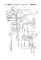
- FIG. 1is a schematic diagram of the desiccant assisted air conditioning system of the present invention, characterized by after cooling means, a cooled return air embodiment, that absorbs heat energy resulting in the heat rise from the dehumidifying desiccant and the discharge therefrom that employs waste heat from refrigeration and used for regeneration of the desiccant.
- FIG. 2is a perspective diagram of the rotary desicant wheel of FIG. 1 and its relationship to waste refrigeration heat and to return air and exhaust associated with the after cooling means.
- FIG. 3is a schematic diagram, similar to a portion of FIG. 1, showing an embodiment of the invention characterized by the after cooling means applied to a packed type desiccaant dehumidifier.
- FIG. 4is a perspective diagram of the packed type dehumidifier, illustrating its relationship to the waste refrigeration heat and to cooled return air associated with the after cooling means.
- FIG. 5is a schematic diagram similar to FIG. 1, showing an embodiment of the invention characterized by the after cooling means employing heat pipes that absorb heat energy resulting in the heat rise from the dehumidifying desiccant.
- FIG. 6is a perspective fragmentary section of a heat pipe configuration employed in the embodiment of FIG. 5, and
- FIG. 6ais a sectional view showing an improved form of heat pipe, finned for efficiency, it being understood that the solid desiccant wheel can be substituted for by the packed type desiccant of FIG. 3 when employing heat pipes for energy transfer.
- FIG. 7is a psychometric graph of this desiccant dehumidification plus sensible cooling process without reheat, compared with a conventional refrigeration process using sensible cooling and dehumidification plus reheat.
- FIG. 8is a diagram of said conventioanl process
- FIG. 9is a diagram of this invention and its desiccant dehumification.
- this inventionprovides a Desiccant Assisted Air Conditioner which is characterized by desiccant dehumification plus sensible cooling.
- OSAoutside air
- RAreturn air
- SAsupply air
- an outside air inlet duct 13for induction of minimum outside air to be dehumidified
- an outside air inlet duct 14for induction of maximim outside air to be mixed with the dehumidified air from duct 13
- a supply air duct 15into the air conditioned space
- a return air duct 16from the air conditioned space
- the exhaust duct 10 and variable damper control means 11that separates the required volume of return air from duct 16.
- the damper control means 11 and 12operate independently and/or together, and inversely proportion the two columns of air as may be required upon demand for 100% air circulation through the cooling coil 9.
- return air (RA)enters through the refrigeration cooling coil 9 at 2 and is discharged as supply air (SA) at 3.
- SAsupply air
- the refrigeration energy lineextends to 4
- the refrigeration energy line in this process shown in FIG. 9extends only to 3; a substantially lower energy use without the requirement for reheating.
- the energy saving with this inventioncan be 10% to 15% and reheating after refrigeration is eliminated.
- the dehumidifier means Dcan vary in form and mode of operation as may be required, and is of the regeneration type having a dehumifying section 20 in the outside air inlet duct 13 and having a regenerating section 21 in a separate outside air duct 22.
- the dehumidifying section 20discharges through a heat exchanger 23 and into the outside air inlet duct 14 ahead of the refrigeration cooling coil 9, whereby the heat rise due to desiccant dehumidification is reduced and/or removed from the induced column of air through duct 13.
- Heat exchanger 23is part of the after cooling means C as will be described. As shown in FIG.
- the desiccant dehumidifier means Dis a solid desiccant wheel, whereas the dehumidifier means D' shown in FIGS. 3 and 4 is a packed type apparatus which is stationary.
- the desiccant wheel 25 of FIGS. 1 and 2revolves by means of a variable speed motor and control means 26.
- the packed type desiccant dehumidifier D'is comprised of stationary sections 20' and 21' for dehumidifying and regeneration respectively.
- a desiccant spray bar 27 supplied with desiccant from a desuperheating means 28discharges through the core of regenerating section 21' and into a sump 29 from which it flows through a spraybar 30 for discharge through the core of the dehumidifying section 20' and into a sump 31 from which it is circulated by a pump P through a cooling coil 32 immersed in the sump 29 and recirculated through the desuperheating means 28.
- the hot suction refrigeration gaspasses through the desuperheating means 28 for decreasing its temperature, thereby removing its superheat while causing an increase in the temperature of the spent desiccant, to assist in its subsequent regeneration by liberating the moisture therefrom.
- a portion of the refrigeration gas dischargeis routed through the desuperheater means 28, a part of the refrigeration coil, where heat is removed.
- This cooler desuperheated gasreturns to the compressor and is mixed with the discharge gas to produce a cooler more dense mixture that passes over the motor and its windings to remove more heat than possible with gas that is not desuperheated.
- the dehumidified air passing through the dehumidifier section 20 or 20'experiences a heat rise that is reduced if not eliminated by the after cooling means C as will be described.
- the refrigeration means Ris shown for refrigeration only, though it may be a heat pump means when so desired.
- the above described desuperheating means 28 connectionis adjacent to the refrigerant discharge so that much of the oil passing through the compressor will be entrained with the gas flowing into the coil of the desuperheater means 28. This oil will then be carried with the gas and returned to the compressor to be mixed with the oil returning from the motor and integral separating elements, all of which are cooled thereby.
- the resulting drop in compressor temperaturewill cause less superheating of the suction gas and a greater mass flow rate.
- liquid injection into the comnpressoris at 36, into the compressor shell, which does not decrease compressor capacity, as a full suction volume will have been taken into the compressor shell before the liquid flashes or expands. Power consumption and system charge will only be marginally higher, approximately 1° to 2°.
- the refrigeration means Rabsorbs heat from the two columns of air emanating from the inlet duct 13 and recirculation duct 14, by means of the evaporative cooling coil 9. Refrigerated air passing through coil 9 is delivered by a blower 37 through the duct 15 as supply air (SA).
- the minimum outside air (OSA) entering through duct 13experiences a significant heat rise as it is dehumidified when passing through the dehumidifier section 20 (20'), and this unwanted heat is immediately removed by the after cooling means C
- the refrigeration means Rdissipates heat from the condenser coil 34 placed in the outside air (OSA) inlet duct 22, so as to heat that column of air for desiccant regeneration by passing the same through the regenerating section 21 (21') of the dehumidifier means D.
- the column of air passing through the regenerating sectiontakes on moisture and is exhausted at 38. Supplemental heat can be applied to the column of air in duct 22 as by heater means 39, an electrical heater as shown.
- the after cooling means Cinvolves the exhaust duct 10 that is supplied with relief air by variable speed blower means 40' that draws return air from duct 16. A portion of all of the exhaust air (25%) is available as relief air.
- the air exhausted through duct 10is demumidified as it comes from the air conditioned building space, and accordingly will support an evaporative cooling process for its further cooling.
- evaporative cooling means 41is provided in the relief air duct 40, following a relief air damper and control means 42 that selects the required volume of relief air for reducing and/or eliminating the heat rise experienced through the dehumidifier section 20 (20').
- the column of evaporatively cooled relief airis discharged through the heat exchanger 23 to absorb the heat rise discharge from the dehumidifier section 20 (20'), controlling and/or reducing the induction air temperature from duct 13 so that air temperature ahead of the cooling coil 19 is at or less than 55° F., thereby precluding icing.
- the cooling surfacesmust be below freezing to obtain desired results, because condensed moisture will freeze on the cooling coils and cannot be drained off during operation.
- ice or frost build-upreduces efficiency and impedes air flow.
- relief air through duct 40is advantageously employed as it progresses through the process of evaporative cooling in order to absorb unwanted heat resulting from dehumidification at heat exchanger 23, and through the process of heat absorption in said heat exhanger 23 and usefully employed in the desiccant regeneration process at regeneration section 21 (21') of the dehumidfying means D.
- the after cooling means C'involves the relief air duct 40' that draws a portion ar all of the exhaust air from the exhaust duct 10.
- the air exhausted through duct 10is return air (RA) which remains substantially dehumidified as it comes from the air conditioned building space, and accordingly will support an evaporative cooling process for its further cooling.
- the evaporative cooling means 41is employed following the variable air damper and control means 11 as hereinabove described.
- heat pipes 50replace the heat exchanger 23 and transfer duct 43, the relief air duct now exhausting directly to atmosphere as shown.
- the heat pipes 50are combined with and operate between the relief air duct 40' and discharge of the minimum outside air (OSA) inlet duct 13, at the discharge thereof into the recirculation duct 14, after the heat rise from the dehumidifier section 20 (20').
- the heat pipes 50are characterized by a hot end 52 for absorbtion of heat and by a cold end 51 for dissipation of heat. In other words, there is a "heat in” end 52 and a "heat out” end 51.
- each heat pipeis placed in the relief air duct 40' following the evaporative cooling means 41, and the "heat in” hot end 52 of each heat pipe is placed in the discharge of the inlet duct 13 following the dehumidifier section 20 (20'). Accordingly, there is a heat transfer that occurs between ducts 40' and 13, and controlled so as to reduce the induction air temperature from duct 13 so that air temperature ahead of the cooling coil 9 is at or no less than 55° F.
- Transfer of heat energy from the discharge end of the inlet duct 13 and the exhaust or relief air duct 40'is by means of a bank comprised of a multiplicity of heat pipes, the cold ends 51 in the form of heat dissipaters placed in the exhaust discharge of duct 40' and the hot ends 52 in the form of heat absorbers placed in the discharge of duct 13 into the duct 14 ahead of the evaporative cooling coil 9.
- the heat pipesare short lengths of heat conductive material, tubing sealed at their ends, having fitting tubular wicks 54 and charged with a refrigerant 55, a gas-liquid. A temperature differential between the ends of each pipe causes the refrigerant 55, liquid to migrate by capillary action to the warmer end where evaporation thereof takes place and absorbs heat.
- the resultant refrigerant vaporthen returns through the hollow tube center of the wick and to the cooler end of the pipe, where it gives up the heat carried thereby, by condensing into the wick in order to repeat the cycle.
- This heat transfer processis efficient, as the heat pipes 50 are sealed and have no moving parts and require little or no maintainance.
- the heat pipes 50'are finned at 56 for most efficient heat energy transfer.
- control meansis provided to coordinate the air column circulation of the several columns of moving air involved.
- control means Kas shown in FIG. 1 which employs Constant Volume Variable Temperature control
- control means K'as shown in FIG. 5 wich employs Variable Volume Constant Temperature control.
- control means K and K'there are means repsonsive to both temperature and humidity and which together govern the operation of the various means involved.
- control means KK (K') responsive to the air conditioned space temperature and humidity as by temperature sensor means means 60 and humidity sensor means 61 and responsive to outside air temperature and mixed intake air temperature as by temperature sensor means 62 and 63 placed in the ouside air inlet duct 14 and at the entry or mixed air into the evaporator cooling coil 9.
- KK'
- the refrigeration and dehumidification function outputsvary according to the temperature and humidity requirements in response to the aforesaid sensor means.
- the air volume or air temperaturemay be inversely employed according to either of the types or modes of operation, as next described.
- minimum outside air intake through duct 13is adjustably controlled by a fixed damper 64, while the drive motor 65 operates the blower 37 at a constant speed for delivery of supply air through duct 15.
- the control means Kcoordinates the temperature and humidity information from sensor means 60-63; so as to control the variable speed motor 26 driving the desiccant wheel 25, through inverter means 66, increased speed removing more moisture; so as to inversely control the positions of the damper and control means 11 and 12 through actuator means 67 and 68, in order for example to maximize cooling with outside air; so as to control the speed of the blower means 40', through an actuator 70, in order to provide air flow commensurate with the position of the damper and control means 11; so as to control the position of damper and control means 42 with repsect to the position of damper and control means 11 and 12, through actuator means 69; so as to control the speed of the compressor and motor means 33 of the refrigeration means, through an inverter means 71, in order to avoid cycling losses; and so as to control the speed of variable speed motor 72 driving the blower 44, through an inverter means 72, in order to control the air temperature for desiccant regeneration and/or rejection of compressor heat; all as circumstances require, it being understood
- variable volume Constant Temperature mode of operationshown in FIG. 5 of the drawings, minimum outside air intake through duct 13 is by blower means 75 controlled for a variable rate of intake volume driven at a variable rate of intake volume by a variable speed motor 76 having inverter means 77, while the blower 37 is driven by a variable speed motor 65 controlled by an inverter means 77' responsive to the control means K'.
- the inverter means 66varies the speed of the desiccant wheel 50
- the inverter means 71varies the speed of the compressor means 33
- the inverter means 78varies the speed of the blower 44 and motor 72
- the actuator means 67 and 68control the positions of damper and control means 11 and 12
- the inverter means 70controls the speed of blower means 40'
- the actuator means 69controls the position of damper and control means 42, all as hereinabove described with respect to the Constant Volume Variable Temperature Control.
- the control means K'coordinates the temperature and humidity information from sensor means 60-63, so as to control the motors and dampers as shown, and further so as to control the speed of motor 65 through the inverter means 77, all as circumstances require, it being understood that state of the art means are implemented for the functions herein described.
- variable speed motor 78the packed type desiccant dehumidifier and desuperheater 28 are operated at variable outputs by control of variable speed motor 78, through an inverter means 79 responsive to the control means K (K'), all as circumstances may require, it being understood that state of the art means are employed for the functions herein described.
Landscapes
- Engineering & Computer Science (AREA)
- Mechanical Engineering (AREA)
- General Engineering & Computer Science (AREA)
- Chemical & Material Sciences (AREA)
- Combustion & Propulsion (AREA)
- Physics & Mathematics (AREA)
- Thermal Sciences (AREA)
- Life Sciences & Earth Sciences (AREA)
- Sustainable Development (AREA)
- Central Air Conditioning (AREA)
Abstract
Description
Claims (19)
Priority Applications (1)
| Application Number | Priority Date | Filing Date | Title |
|---|---|---|---|
| US07/315,592US4887438A (en) | 1989-02-27 | 1989-02-27 | Desiccant assisted air conditioner |
Applications Claiming Priority (1)
| Application Number | Priority Date | Filing Date | Title |
|---|---|---|---|
| US07/315,592US4887438A (en) | 1989-02-27 | 1989-02-27 | Desiccant assisted air conditioner |
Publications (1)
| Publication Number | Publication Date |
|---|---|
| US4887438Atrue US4887438A (en) | 1989-12-19 |
Family
ID=23225144
Family Applications (1)
| Application Number | Title | Priority Date | Filing Date |
|---|---|---|---|
| US07/315,592Expired - LifetimeUS4887438A (en) | 1989-02-27 | 1989-02-27 | Desiccant assisted air conditioner |
Country Status (1)
| Country | Link |
|---|---|
| US (1) | US4887438A (en) |
Cited By (127)
| Publication number | Priority date | Publication date | Assignee | Title |
|---|---|---|---|---|
| US5170633A (en)* | 1991-06-24 | 1992-12-15 | Amsted Industries Incorporated | Desiccant based air conditioning system |
| US5191771A (en)* | 1991-07-05 | 1993-03-09 | Milton Meckler | Polymer desiccant and system for dehumidified air conditioning |
| US5251458A (en)* | 1991-08-19 | 1993-10-12 | Tchernev Dimiter I | Process and apparatus for reducing the air cooling and water removal requirements of deep-level mines |
| US5279609A (en)* | 1992-10-30 | 1994-01-18 | Milton Meckler | Air quality-temperature controlled central conditioner and multi-zone conditioning |
| US5325676A (en)* | 1992-08-24 | 1994-07-05 | Milton Meckler | Desiccant assisted multi-use air pre-conditioner unit with system heat recovery capability |
| US5373704A (en)* | 1990-04-17 | 1994-12-20 | Arthur D. Little, Inc. | Desiccant dehumidifier |
| US5423187A (en)* | 1993-11-30 | 1995-06-13 | Bernard Fournier | Rooftop air conditioning unit and method of modification with a rotary regenerative heat exchanger |
| US5426953A (en)* | 1993-02-05 | 1995-06-27 | Meckler; Milton | Co-sorption air dehumidifying and pollutant removal system |
| US5448895A (en)* | 1993-01-08 | 1995-09-12 | Engelhard/Icc | Hybrid heat pump and desiccant space conditioning system and control method |
| WO1995028609A1 (en)* | 1992-08-24 | 1995-10-26 | Milton Meckler | Desiccant assisted multi-use air pre-conditioner unit with system heat recovery capability |
| US5512083A (en)* | 1993-10-25 | 1996-04-30 | Uop | Process and apparatus for dehumidification and VOC odor remediation |
| US5526651A (en)* | 1994-07-15 | 1996-06-18 | Gas Research Institute | Open cycle desiccant cooling systems |
| US5564281A (en)* | 1993-01-08 | 1996-10-15 | Engelhard/Icc | Method of operating hybrid air-conditioning system with fast condensing start-up |
| US5566880A (en)* | 1993-02-11 | 1996-10-22 | Behr Gmbh & Co. | Process and apparatus for heating the passenger compartment of a motor vehicle |
| US5579647A (en)* | 1993-01-08 | 1996-12-03 | Engelhard/Icc | Desiccant assisted dehumidification and cooling system |
| US5667560A (en)* | 1993-10-25 | 1997-09-16 | Uop | Process and apparatus for dehumidification and VOC odor remediation |
| US5718122A (en)* | 1996-01-12 | 1998-02-17 | Ebara Corporation | Air conditioning system |
| DE19637156A1 (en)* | 1996-09-12 | 1998-03-26 | Zae Bayern Bayerisches Zentrum Fuer Angewandte Energieforschung Ev | Air-conditioner using combined air cooling modes |
| US5749230A (en)* | 1991-01-18 | 1998-05-12 | Engelhard/Icc | Method for creating a humidity gradient within an air conditioned zone |
| US5758509A (en)* | 1995-12-21 | 1998-06-02 | Ebara Corporation | Absorption heat pump and desiccant assisted air conditioning apparatus |
| US5761923A (en)* | 1996-01-12 | 1998-06-09 | Ebara Corporation | Air conditioning system |
| US5761925A (en)* | 1995-12-21 | 1998-06-09 | Ebara Corporation | Absorption heat pump and desiccant assisted air conditioner |
| US5768897A (en)* | 1992-06-16 | 1998-06-23 | Universal Dynamics Corporation | Air drying apparatus and method with high ratio gas flow to absorber weight |
| US5791157A (en)* | 1996-01-16 | 1998-08-11 | Ebara Corporation | Heat pump device and desiccant assisted air conditioning system |
| US5816065A (en)* | 1996-01-12 | 1998-10-06 | Ebara Corporation | Desiccant assisted air conditioning system |
| US5873256A (en)* | 1994-07-07 | 1999-02-23 | Denniston; James G. T. | Desiccant based humidification/dehumidification system |
| US5931015A (en)* | 1996-06-20 | 1999-08-03 | Ebara Corporation | Desiccant assisted air conditioning system |
| US5931016A (en)* | 1997-10-13 | 1999-08-03 | Advanced Thermal Technologies, Llc | Air conditioning system having multiple energy regeneration capabilities |
| US5943874A (en)* | 1996-09-24 | 1999-08-31 | Ebara Corporation | Desiccant assisted air conditioning apparatus |
| JP2948776B2 (en) | 1997-03-25 | 1999-09-13 | 株式会社荏原製作所 | Air conditioning system |
| US5950442A (en)* | 1996-05-24 | 1999-09-14 | Ebara Corporation | Air conditioning system |
| US5950447A (en)* | 1996-05-24 | 1999-09-14 | Ebara Corporation | Desiccant assisted air conditioning system |
| US5953926A (en)* | 1997-08-05 | 1999-09-21 | Tennessee Valley Authority | Heating, cooling, and dehumidifying system with energy recovery |
| JP2968241B2 (en) | 1997-10-24 | 1999-10-25 | 株式会社荏原製作所 | Dehumidifying air conditioning system and operating method thereof |
| JP2968224B2 (en) | 1997-01-21 | 1999-10-25 | 株式会社荏原製作所 | Air conditioners and air conditioning systems |
| JP2968231B2 (en) | 1997-04-11 | 1999-10-25 | 株式会社荏原製作所 | Air conditioning system |
| JP2968230B2 (en) | 1997-03-25 | 1999-10-25 | 株式会社荏原製作所 | Air conditioning system |
| JP2968232B2 (en) | 1997-04-11 | 1999-10-25 | 株式会社荏原製作所 | Air conditioning system and operating method thereof |
| JP2994292B2 (en) | 1996-12-27 | 1999-12-27 | 株式会社荏原製作所 | Air conditioners and air conditioning systems |
| JP2994303B2 (en) | 1997-04-11 | 1999-12-27 | 株式会社荏原製作所 | Air conditioning system and operating method thereof |
| US6029462A (en)* | 1997-09-09 | 2000-02-29 | Denniston; James G. T. | Desiccant air conditioning for a motorized vehicle |
| US6038879A (en)* | 1995-08-08 | 2000-03-21 | Yvon Turcotte | Combined air exchange and air conditioning unit |
| US6199392B1 (en) | 1997-03-25 | 2001-03-13 | Ebara Corporation | Air conditioning system |
| WO2001067002A1 (en)* | 2000-03-06 | 2001-09-13 | Honeywell International Inc. | Heat recovery ventilator with make-up air capability |
| US6318106B1 (en) | 1997-10-09 | 2001-11-20 | Ebara Corporation | Dehumidifying air conditioner |
| US6334316B1 (en) | 1998-03-17 | 2002-01-01 | Ebara Corporation | Desiccant assisted air conditioning system |
| US6370900B1 (en) | 1998-09-16 | 2002-04-16 | Ebara Corporation | Dehumidifying air-conditioning apparatus and dehumidifying air-conditioning system |
| US6434857B1 (en) | 2000-07-05 | 2002-08-20 | Smartclean Jv | Combination closed-circuit washer and drier |
| US6442951B1 (en)* | 1998-06-30 | 2002-09-03 | Ebara Corporation | Heat exchanger, heat pump, dehumidifier, and dehumidifying method |
| US6487872B1 (en) | 1997-11-16 | 2002-12-03 | Drykor Ltd. | Dehumidifier system |
| US6494053B1 (en)* | 1999-03-14 | 2002-12-17 | Drykor, Ltd. | Dehumidifier/air-conditioning system |
| US20030070787A1 (en)* | 2001-09-17 | 2003-04-17 | Moffitt Ronnie R. | Dual exhaust energy recovery system |
| US6575228B1 (en) | 2000-03-06 | 2003-06-10 | Mississippi State Research And Technology Corporation | Ventilating dehumidifying system |
| US6637234B2 (en)* | 2001-01-25 | 2003-10-28 | Federico Rossetto | Method of air conditioning interiors and air conditioning unit for said method |
| EP1367333A4 (en)* | 2001-03-07 | 2003-12-03 | Ebara Corp | Heat pump and dehumidifier |
| US6675601B2 (en)* | 2001-10-18 | 2004-01-13 | Sanyo Electric Co., Ltd. | Air conditioner |
| US20040060315A1 (en)* | 2001-02-28 | 2004-04-01 | Munters Corporation | Desiccant refrigerant dehumidifier systems |
| US6813894B2 (en) | 1999-08-31 | 2004-11-09 | Ebara Corporation | Heat pump and dehumidifier |
| US20050268903A1 (en)* | 2004-06-08 | 2005-12-08 | Bassilakis Harry C | Variable volumetric flow heat exchanger for an air-to-air heat recovery system |
| US20050268633A1 (en)* | 2004-06-08 | 2005-12-08 | Smith Douglas M | Sorption cooling systems, their use in automotive cooling applications and methods relating to the same |
| US6976365B2 (en) | 1997-11-16 | 2005-12-20 | Drykor Ltd. | Dehumidifier/air-conditioning system |
| US20060005560A1 (en)* | 2004-07-09 | 2006-01-12 | Maurice Lattanzio | Energy recovery unit |
| US20060117769A1 (en)* | 2004-12-07 | 2006-06-08 | American Standard International Inc. | Ventilation controller |
| US20060162366A1 (en)* | 2002-02-06 | 2006-07-27 | Jose Moratalla | Desiccant dehumidification system |
| EP1912033A1 (en)* | 2006-10-12 | 2008-04-16 | Nederlandse Organisatie voor Toegepast-Natuuurwetenschappelijk Onderzoek TNO | Process for controlling the moisture content of a supply gas for use in drying a product |
| US20080276640A1 (en)* | 2007-05-10 | 2008-11-13 | Mohinder Singh Bhatti | Evaporative cooler and desiccant assisted vapor compression AC system |
| US20100005821A1 (en)* | 2008-07-03 | 2010-01-14 | Hydro Heat, Llc | System and Method for Controlling a Refrigeration Desuperheater |
| US7721460B2 (en)* | 2003-12-21 | 2010-05-25 | Albers Walter F | Micro-cycle energy transfer systems and methods |
| US20100242507A1 (en)* | 2009-03-24 | 2010-09-30 | Milton Meckler | Dynamic outside air management system and method |
| US20100275775A1 (en)* | 2009-05-04 | 2010-11-04 | Bry-Air, Inc | Method and system for control of desiccant dehumidifier |
| WO2010128522A1 (en)* | 2009-05-04 | 2010-11-11 | Bry Air [Asia] Pvt. Ltd. | Desiccant unit control system and method |
| FR2950419A1 (en)* | 2009-09-22 | 2011-03-25 | Commissariat Energie Atomique | Heat treatment method for heat treatment system i.e. solar cooling system, involves varying speed of desiccant wheel, where speed of desiccant wheel is function of humidity and temperature of air to be dehumidified in inlet of wheel |
| EP2202467A3 (en)* | 2008-12-23 | 2011-12-07 | Tai-Her Yang | Rotary type heat exchange apparatus with automatic flow rate exchange modulation |
| US20120168119A1 (en)* | 2010-12-30 | 2012-07-05 | Munters Corporation | Ventilation device for use in systems and methods for removing heat from enclosed spaces with high internal heat generation |
| DE10010022B4 (en)* | 1999-03-02 | 2012-07-26 | ZAE Bayern Bayerisches Zentrum für angewandte Energieforschung eV | Sorption-based air conditioning |
| US20130025450A1 (en)* | 2011-07-29 | 2013-01-31 | Ratnesh Kumar Sharma | Systems and methods to condition air |
| US8601716B2 (en)* | 2003-07-30 | 2013-12-10 | Bsh Bosch Und Siemens Hausgeraete Gmbh | Method for operating a device with at least one partial programme step of drying |
| ITMI20122084A1 (en)* | 2012-12-06 | 2014-06-07 | Climaveneta S P A | AIR HANDLING UNIT ENTRY INTO AN ENVIRONMENT |
| US20140190656A1 (en)* | 2013-01-07 | 2014-07-10 | Carrier Corporation | Energy recovery ventilator |
| US8800308B2 (en) | 2010-05-25 | 2014-08-12 | 7Ac Technologies, Inc. | Methods and systems for desiccant air conditioning with combustion contaminant filtering |
| US9032742B2 (en) | 2010-12-30 | 2015-05-19 | Munters Corporation | Methods for removing heat from enclosed spaces with high internal heat generation |
| US9055696B2 (en) | 2010-12-30 | 2015-06-09 | Munters Corporation | Systems for removing heat from enclosed spaces with high internal heat generation |
| US9101875B2 (en) | 2012-06-11 | 2015-08-11 | 7Ac Technologies, Inc. | Methods and systems for turbulent, corrosion resistant heat exchangers |
| WO2015125251A1 (en)* | 2014-02-20 | 2015-08-27 | 三菱電機株式会社 | Air-conditioning device and method for controlling air-conditioning device |
| US9234665B2 (en) | 2010-06-24 | 2016-01-12 | Nortek Air Solutions Canada, Inc. | Liquid-to-air membrane energy exchanger |
| US20160169544A1 (en)* | 2014-12-15 | 2016-06-16 | Semco Llc | Unit with recovery wheel and economizer and method of control |
| EP2929256A4 (en)* | 2012-12-04 | 2016-08-03 | 7Ac Technologies Inc | METHODS AND SYSTEMS FOR COOLING BUILDINGS WITH HIGH THERMAL LOADS THROUGH DESICCANT COOLERS |
| WO2016140994A1 (en)* | 2015-03-02 | 2016-09-09 | Sylvan Source, Inc. | High-efficiency desalination |
| WO2016146133A1 (en)* | 2015-03-15 | 2016-09-22 | Cotes A/S | A cooling system, a cooling unit, and a method of cooling intake-air to an air-conditioned building space |
| US9470426B2 (en) | 2013-06-12 | 2016-10-18 | 7Ac Technologies, Inc. | In-ceiling liquid desiccant air conditioning system |
| US20160363358A1 (en)* | 2015-06-09 | 2016-12-15 | Carrier Corporation | System and method of diluting a leaked refrigerant in an hvac/r system |
| US9631848B2 (en) | 2013-03-01 | 2017-04-25 | 7Ac Technologies, Inc. | Desiccant air conditioning systems with conditioner and regenerator heat transfer fluid loops |
| US9709285B2 (en) | 2013-03-14 | 2017-07-18 | 7Ac Technologies, Inc. | Methods and systems for liquid desiccant air conditioning system retrofit |
| US9772124B2 (en) | 2013-03-13 | 2017-09-26 | Nortek Air Solutions Canada, Inc. | Heat pump defrosting system and method |
| US9810439B2 (en) | 2011-09-02 | 2017-11-07 | Nortek Air Solutions Canada, Inc. | Energy exchange system for conditioning air in an enclosed structure |
| US9816760B2 (en) | 2012-08-24 | 2017-11-14 | Nortek Air Solutions Canada, Inc. | Liquid panel assembly |
| US9885486B2 (en) | 2010-08-27 | 2018-02-06 | Nortek Air Solutions Canada, Inc. | Heat pump humidifier and dehumidifier system and method |
| US9909768B2 (en) | 2013-03-13 | 2018-03-06 | Nortek Air Solutions Canada, Inc. | Variable desiccant control energy exchange system and method |
| US20180073756A1 (en)* | 2014-10-31 | 2018-03-15 | Honeywell International Inc. | Economizer having damper modulation |
| US9920960B2 (en) | 2011-01-19 | 2018-03-20 | Nortek Air Solutions Canada, Inc. | Heat pump system having a pre-processing module |
| US10024558B2 (en) | 2014-11-21 | 2018-07-17 | 7Ac Technologies, Inc. | Methods and systems for mini-split liquid desiccant air conditioning |
| US20180202702A1 (en)* | 2017-01-18 | 2018-07-19 | Heatcraft Refrigeration Products Llc | System and method for reducing moisture in a refrigerated room |
| US20180328603A1 (en)* | 2015-11-18 | 2018-11-15 | Kyungdong Navien Co., Ltd. | Air conditioner capable of controlling heating and humidity, and control method therefor |
| US10240807B2 (en)* | 2014-11-24 | 2019-03-26 | Korea Institute Of Science And Technology | Desiccant cooling system |
| US10274210B2 (en) | 2010-08-27 | 2019-04-30 | Nortek Air Solutions Canada, Inc. | Heat pump humidifier and dehumidifier system and method |
| US10323867B2 (en) | 2014-03-20 | 2019-06-18 | 7Ac Technologies, Inc. | Rooftop liquid desiccant systems and methods |
| US10350536B2 (en) | 2016-11-09 | 2019-07-16 | Climate By Design International, Inc. | Reverse flow dehumidifier and methods of operating the same |
| US10352628B2 (en) | 2013-03-14 | 2019-07-16 | Nortek Air Solutions Canada, Inc. | Membrane-integrated energy exchange assembly |
| US10584884B2 (en) | 2013-03-15 | 2020-03-10 | Nortek Air Solutions Canada, Inc. | Control system and method for a liquid desiccant air delivery system |
| US10619867B2 (en) | 2013-03-14 | 2020-04-14 | 7Ac Technologies, Inc. | Methods and systems for mini-split liquid desiccant air conditioning |
| US10653042B2 (en) | 2016-11-11 | 2020-05-12 | Stulz Air Technology Systems, Inc. | Dual mass cooling precision system |
| US10712024B2 (en) | 2014-08-19 | 2020-07-14 | Nortek Air Solutions Canada, Inc. | Liquid to air membrane energy exchangers |
| US10775059B2 (en)* | 2015-11-18 | 2020-09-15 | Kyungdong Navien Co., Ltd. | Air conditioning capable of controlling ventilation and humidity, and control method therefor |
| US10782045B2 (en) | 2015-05-15 | 2020-09-22 | Nortek Air Solutions Canada, Inc. | Systems and methods for managing conditions in enclosed space |
| US10808951B2 (en) | 2015-05-15 | 2020-10-20 | Nortek Air Solutions Canada, Inc. | Systems and methods for providing cooling to a heat load |
| US10921001B2 (en) | 2017-11-01 | 2021-02-16 | 7Ac Technologies, Inc. | Methods and apparatus for uniform distribution of liquid desiccant in membrane modules in liquid desiccant air-conditioning systems |
| US10941948B2 (en) | 2017-11-01 | 2021-03-09 | 7Ac Technologies, Inc. | Tank system for liquid desiccant air conditioning system |
| US10962252B2 (en) | 2015-06-26 | 2021-03-30 | Nortek Air Solutions Canada, Inc. | Three-fluid liquid to air membrane energy exchanger |
| US11022330B2 (en) | 2018-05-18 | 2021-06-01 | Emerson Climate Technologies, Inc. | Three-way heat exchangers for liquid desiccant air-conditioning systems and methods of manufacture |
| CN113124507A (en)* | 2021-05-21 | 2021-07-16 | 珠海格力电器股份有限公司 | Dehumidifier |
| US11092349B2 (en) | 2015-05-15 | 2021-08-17 | Nortek Air Solutions Canada, Inc. | Systems and methods for providing cooling to a heat load |
| US11231211B2 (en)* | 2019-04-02 | 2022-01-25 | Johnson Controls Technology Company | Return air recycling system for an HVAC system |
| US11408681B2 (en) | 2013-03-15 | 2022-08-09 | Nortek Air Solations Canada, Iac. | Evaporative cooling system with liquid-to-air membrane energy exchanger |
| US11892193B2 (en) | 2017-04-18 | 2024-02-06 | Nortek Air Solutions Canada, Inc. | Desiccant enhanced evaporative cooling systems and methods |
| IT202200020289A1 (en) | 2022-10-03 | 2024-04-03 | Green Being Soc Benefit A Responsabilita Limitata | IMPROVED INDOOR SYSTEM FOR THE CONSTRUCTION OF SELF-SUFFICIENT GREEN WALLS, AND CULTIVATION PROCEDURE FOR THE GREEN WALLS OBTAINED THUS. |
| US12385654B2 (en) | 2017-04-18 | 2025-08-12 | Nortek Air Solutions Canada, Inc. | Systems and methods for managing conditions in enclosed space |
| US12442558B2 (en) | 2023-09-29 | 2025-10-14 | Nortek Air Solutions Canada, Inc. | Using liquid to air membrane energy exchanger for liquid cooling |
Citations (9)
| Publication number | Priority date | Publication date | Assignee | Title |
|---|---|---|---|---|
| US3488971A (en)* | 1968-04-29 | 1970-01-13 | Gershon Meckler | Comfort conditioning system |
| US3774374A (en)* | 1971-06-09 | 1973-11-27 | Gas Dev Corp | Environmental control unit |
| US4024908A (en)* | 1976-01-29 | 1977-05-24 | Milton Meckler | Solar powered heat reclamation air conditioning system |
| US4300623A (en)* | 1978-10-10 | 1981-11-17 | Milton Meckler | Integrated multi-duct dual-stage dual-cooling media air conditioning system |
| US4474021A (en)* | 1982-02-02 | 1984-10-02 | Joel Harband | Heat pump apparatus and method |
| US4691530A (en)* | 1986-09-05 | 1987-09-08 | Milton Meckler | Cogeneration and central regeneration multi-contactor air conditioning system |
| US4719761A (en)* | 1986-05-30 | 1988-01-19 | Cromer Charles J | Cooling system |
| US4730461A (en)* | 1987-06-05 | 1988-03-15 | Milton Meckler | Multi-zone cold storage variable air volume air conditioning system |
| US4739624A (en)* | 1987-02-20 | 1988-04-26 | Milton Meckler | Multi-zone thermal energy storage variable air volume hydronic heat pump system |
- 1989
- 1989-02-27USUS07/315,592patent/US4887438A/ennot_activeExpired - Lifetime
Patent Citations (9)
| Publication number | Priority date | Publication date | Assignee | Title |
|---|---|---|---|---|
| US3488971A (en)* | 1968-04-29 | 1970-01-13 | Gershon Meckler | Comfort conditioning system |
| US3774374A (en)* | 1971-06-09 | 1973-11-27 | Gas Dev Corp | Environmental control unit |
| US4024908A (en)* | 1976-01-29 | 1977-05-24 | Milton Meckler | Solar powered heat reclamation air conditioning system |
| US4300623A (en)* | 1978-10-10 | 1981-11-17 | Milton Meckler | Integrated multi-duct dual-stage dual-cooling media air conditioning system |
| US4474021A (en)* | 1982-02-02 | 1984-10-02 | Joel Harband | Heat pump apparatus and method |
| US4719761A (en)* | 1986-05-30 | 1988-01-19 | Cromer Charles J | Cooling system |
| US4691530A (en)* | 1986-09-05 | 1987-09-08 | Milton Meckler | Cogeneration and central regeneration multi-contactor air conditioning system |
| US4739624A (en)* | 1987-02-20 | 1988-04-26 | Milton Meckler | Multi-zone thermal energy storage variable air volume hydronic heat pump system |
| US4730461A (en)* | 1987-06-05 | 1988-03-15 | Milton Meckler | Multi-zone cold storage variable air volume air conditioning system |
Cited By (211)
| Publication number | Priority date | Publication date | Assignee | Title |
|---|---|---|---|---|
| US5373704A (en)* | 1990-04-17 | 1994-12-20 | Arthur D. Little, Inc. | Desiccant dehumidifier |
| US5749230A (en)* | 1991-01-18 | 1998-05-12 | Engelhard/Icc | Method for creating a humidity gradient within an air conditioned zone |
| US5170633A (en)* | 1991-06-24 | 1992-12-15 | Amsted Industries Incorporated | Desiccant based air conditioning system |
| US5191771A (en)* | 1991-07-05 | 1993-03-09 | Milton Meckler | Polymer desiccant and system for dehumidified air conditioning |
| US5251458A (en)* | 1991-08-19 | 1993-10-12 | Tchernev Dimiter I | Process and apparatus for reducing the air cooling and water removal requirements of deep-level mines |
| US5768897A (en)* | 1992-06-16 | 1998-06-23 | Universal Dynamics Corporation | Air drying apparatus and method with high ratio gas flow to absorber weight |
| US5325676A (en)* | 1992-08-24 | 1994-07-05 | Milton Meckler | Desiccant assisted multi-use air pre-conditioner unit with system heat recovery capability |
| WO1995028609A1 (en)* | 1992-08-24 | 1995-10-26 | Milton Meckler | Desiccant assisted multi-use air pre-conditioner unit with system heat recovery capability |
| USRE37464E1 (en) | 1992-08-24 | 2001-12-11 | Milton Meckler | Desiccant assisted multi-use air pre-conditioner unit with system heat recovery capability |
| WO1995019534A1 (en)* | 1992-10-30 | 1995-07-20 | Milton Meckler | Air quality-temperature controlled central conditioner and multi-zoned conditioning |
| US5279609A (en)* | 1992-10-30 | 1994-01-18 | Milton Meckler | Air quality-temperature controlled central conditioner and multi-zone conditioning |
| US5448895A (en)* | 1993-01-08 | 1995-09-12 | Engelhard/Icc | Hybrid heat pump and desiccant space conditioning system and control method |
| US5564281A (en)* | 1993-01-08 | 1996-10-15 | Engelhard/Icc | Method of operating hybrid air-conditioning system with fast condensing start-up |
| US5579647A (en)* | 1993-01-08 | 1996-12-03 | Engelhard/Icc | Desiccant assisted dehumidification and cooling system |
| US5426953A (en)* | 1993-02-05 | 1995-06-27 | Meckler; Milton | Co-sorption air dehumidifying and pollutant removal system |
| US5566880A (en)* | 1993-02-11 | 1996-10-22 | Behr Gmbh & Co. | Process and apparatus for heating the passenger compartment of a motor vehicle |
| WO1997001066A1 (en)* | 1993-08-04 | 1997-01-09 | Milton Meckler | Co-sorption air dehumidifying and pollutant removal system |
| US5512083A (en)* | 1993-10-25 | 1996-04-30 | Uop | Process and apparatus for dehumidification and VOC odor remediation |
| US5667560A (en)* | 1993-10-25 | 1997-09-16 | Uop | Process and apparatus for dehumidification and VOC odor remediation |
| US5423187A (en)* | 1993-11-30 | 1995-06-13 | Bernard Fournier | Rooftop air conditioning unit and method of modification with a rotary regenerative heat exchanger |
| US6092375A (en)* | 1994-07-07 | 2000-07-25 | Denniston; James G. T. | Desiccant based humidification/dehumidification system |
| US5873256A (en)* | 1994-07-07 | 1999-02-23 | Denniston; James G. T. | Desiccant based humidification/dehumidification system |
| US5526651A (en)* | 1994-07-15 | 1996-06-18 | Gas Research Institute | Open cycle desiccant cooling systems |
| US5542259A (en)* | 1994-07-15 | 1996-08-06 | Gas Research Institute | Open cycle desiccant cooling process |
| WO1996041107A1 (en)* | 1995-06-07 | 1996-12-19 | Engelhard/Icc | Dessicant assisted dehumidification and cooling system |
| US6038879A (en)* | 1995-08-08 | 2000-03-21 | Yvon Turcotte | Combined air exchange and air conditioning unit |
| US5761925A (en)* | 1995-12-21 | 1998-06-09 | Ebara Corporation | Absorption heat pump and desiccant assisted air conditioner |
| CN1129753C (en)* | 1995-12-21 | 2003-12-03 | 株式会社荏原制作所 | Absorption heat pump and desiccant assisted air conditioning apparatus |
| US5758509A (en)* | 1995-12-21 | 1998-06-02 | Ebara Corporation | Absorption heat pump and desiccant assisted air conditioning apparatus |
| US5816065A (en)* | 1996-01-12 | 1998-10-06 | Ebara Corporation | Desiccant assisted air conditioning system |
| US5761923A (en)* | 1996-01-12 | 1998-06-09 | Ebara Corporation | Air conditioning system |
| US5718122A (en)* | 1996-01-12 | 1998-02-17 | Ebara Corporation | Air conditioning system |
| US5791157A (en)* | 1996-01-16 | 1998-08-11 | Ebara Corporation | Heat pump device and desiccant assisted air conditioning system |
| US5966955A (en)* | 1996-01-16 | 1999-10-19 | Ebara Corporation | Heat pump device and desiccant assisted air conditioning system |
| US5950447A (en)* | 1996-05-24 | 1999-09-14 | Ebara Corporation | Desiccant assisted air conditioning system |
| US5950442A (en)* | 1996-05-24 | 1999-09-14 | Ebara Corporation | Air conditioning system |
| US5931015A (en)* | 1996-06-20 | 1999-08-03 | Ebara Corporation | Desiccant assisted air conditioning system |
| US6196014B1 (en) | 1996-06-20 | 2001-03-06 | Ebara Corporation | Desiccant assisted air conditioning system |
| DE19637156A1 (en)* | 1996-09-12 | 1998-03-26 | Zae Bayern Bayerisches Zentrum Fuer Angewandte Energieforschung Ev | Air-conditioner using combined air cooling modes |
| DE19637156C2 (en)* | 1996-09-12 | 1999-02-25 | Zae Bayern Bayerisches Zentrum Fuer Angewandte Energieforschung Ev | Process for air conditioning with a closed absorption chiller in combination with an open sorption chiller |
| US5943874A (en)* | 1996-09-24 | 1999-08-31 | Ebara Corporation | Desiccant assisted air conditioning apparatus |
| JP2994292B2 (en) | 1996-12-27 | 1999-12-27 | 株式会社荏原製作所 | Air conditioners and air conditioning systems |
| JP2968224B2 (en) | 1997-01-21 | 1999-10-25 | 株式会社荏原製作所 | Air conditioners and air conditioning systems |
| JP2948776B2 (en) | 1997-03-25 | 1999-09-13 | 株式会社荏原製作所 | Air conditioning system |
| US6199392B1 (en) | 1997-03-25 | 2001-03-13 | Ebara Corporation | Air conditioning system |
| JP2968230B2 (en) | 1997-03-25 | 1999-10-25 | 株式会社荏原製作所 | Air conditioning system |
| US6205797B1 (en) | 1997-04-11 | 2001-03-27 | Ebara Corporation | Air-conditioning system and method of operating the same |
| JP2994303B2 (en) | 1997-04-11 | 1999-12-27 | 株式会社荏原製作所 | Air conditioning system and operating method thereof |
| JP2968232B2 (en) | 1997-04-11 | 1999-10-25 | 株式会社荏原製作所 | Air conditioning system and operating method thereof |
| JP2968231B2 (en) | 1997-04-11 | 1999-10-25 | 株式会社荏原製作所 | Air conditioning system |
| US6199389B1 (en) | 1997-04-11 | 2001-03-13 | Ebara Corporation | Air Conditioning system and method for operating the same |
| US6247323B1 (en) | 1997-04-11 | 2001-06-19 | Ebara Corporation | Air-conditioning system |
| US5953926A (en)* | 1997-08-05 | 1999-09-21 | Tennessee Valley Authority | Heating, cooling, and dehumidifying system with energy recovery |
| US6029462A (en)* | 1997-09-09 | 2000-02-29 | Denniston; James G. T. | Desiccant air conditioning for a motorized vehicle |
| US6318106B1 (en) | 1997-10-09 | 2001-11-20 | Ebara Corporation | Dehumidifying air conditioner |
| US5931016A (en)* | 1997-10-13 | 1999-08-03 | Advanced Thermal Technologies, Llc | Air conditioning system having multiple energy regeneration capabilities |
| JP2968241B2 (en) | 1997-10-24 | 1999-10-25 | 株式会社荏原製作所 | Dehumidifying air conditioning system and operating method thereof |
| US6976365B2 (en) | 1997-11-16 | 2005-12-20 | Drykor Ltd. | Dehumidifier/air-conditioning system |
| US6487872B1 (en) | 1997-11-16 | 2002-12-03 | Drykor Ltd. | Dehumidifier system |
| US6546746B2 (en) | 1997-11-16 | 2003-04-15 | Drykor Ltd. | Dehumidifier system |
| US6334316B1 (en) | 1998-03-17 | 2002-01-01 | Ebara Corporation | Desiccant assisted air conditioning system |
| US6442951B1 (en)* | 1998-06-30 | 2002-09-03 | Ebara Corporation | Heat exchanger, heat pump, dehumidifier, and dehumidifying method |
| US6370900B1 (en) | 1998-09-16 | 2002-04-16 | Ebara Corporation | Dehumidifying air-conditioning apparatus and dehumidifying air-conditioning system |
| DE10010022B4 (en)* | 1999-03-02 | 2012-07-26 | ZAE Bayern Bayerisches Zentrum für angewandte Energieforschung eV | Sorption-based air conditioning |
| DE10010022B8 (en)* | 1999-03-02 | 2012-11-29 | ZAE Bayern Bayerisches Zentrum für angewandte Energieforschung e.V. | Sorption-based air conditioning |
| US6494053B1 (en)* | 1999-03-14 | 2002-12-17 | Drykor, Ltd. | Dehumidifier/air-conditioning system |
| US6813894B2 (en) | 1999-08-31 | 2004-11-09 | Ebara Corporation | Heat pump and dehumidifier |
| WO2001067002A1 (en)* | 2000-03-06 | 2001-09-13 | Honeywell International Inc. | Heat recovery ventilator with make-up air capability |
| US6575228B1 (en) | 2000-03-06 | 2003-06-10 | Mississippi State Research And Technology Corporation | Ventilating dehumidifying system |
| US6328095B1 (en) | 2000-03-06 | 2001-12-11 | Honeywell International Inc. | Heat recovery ventilator with make-up air capability |
| US6434857B1 (en) | 2000-07-05 | 2002-08-20 | Smartclean Jv | Combination closed-circuit washer and drier |
| US6637234B2 (en)* | 2001-01-25 | 2003-10-28 | Federico Rossetto | Method of air conditioning interiors and air conditioning unit for said method |
| US7047751B2 (en)* | 2001-02-28 | 2006-05-23 | Munters Corporation | Desiccant refrigerant dehumidifier systems |
| US20040060315A1 (en)* | 2001-02-28 | 2004-04-01 | Munters Corporation | Desiccant refrigerant dehumidifier systems |
| US20050050906A1 (en)* | 2001-02-28 | 2005-03-10 | Munters Corporation | Desiccant refrigerant dehumidifier systems |
| EP1367333A4 (en)* | 2001-03-07 | 2003-12-03 | Ebara Corp | Heat pump and dehumidifier |
| US7150314B2 (en) | 2001-09-17 | 2006-12-19 | American Standard International Inc. | Dual exhaust energy recovery system |
| US20030070787A1 (en)* | 2001-09-17 | 2003-04-17 | Moffitt Ronnie R. | Dual exhaust energy recovery system |
| US6675601B2 (en)* | 2001-10-18 | 2004-01-13 | Sanyo Electric Co., Ltd. | Air conditioner |
| US20060162366A1 (en)* | 2002-02-06 | 2006-07-27 | Jose Moratalla | Desiccant dehumidification system |
| US8601716B2 (en)* | 2003-07-30 | 2013-12-10 | Bsh Bosch Und Siemens Hausgeraete Gmbh | Method for operating a device with at least one partial programme step of drying |
| US7721460B2 (en)* | 2003-12-21 | 2010-05-25 | Albers Walter F | Micro-cycle energy transfer systems and methods |
| US20050268903A1 (en)* | 2004-06-08 | 2005-12-08 | Bassilakis Harry C | Variable volumetric flow heat exchanger for an air-to-air heat recovery system |
| US20050268633A1 (en)* | 2004-06-08 | 2005-12-08 | Smith Douglas M | Sorption cooling systems, their use in automotive cooling applications and methods relating to the same |
| US7334632B2 (en)* | 2004-06-08 | 2008-02-26 | Bassilakis Harry C | Variable volumetric flow heat exchanger for an air-to-air heat recovery system |
| US7143589B2 (en) | 2004-06-08 | 2006-12-05 | Nanopore, Inc. | Sorption cooling systems, their use in automotive cooling applications and methods relating to the same |
| US7484381B2 (en)* | 2004-07-09 | 2009-02-03 | Spinnaker Industries Inc. | Energy recovery unit |
| US20060005560A1 (en)* | 2004-07-09 | 2006-01-12 | Maurice Lattanzio | Energy recovery unit |
| US11953216B2 (en)* | 2004-12-07 | 2024-04-09 | Trane International Inc. | Ventilation controller |
| US11199334B2 (en) | 2004-12-07 | 2021-12-14 | Trane International Inc. | Ventilation controller |
| US8702482B2 (en) | 2004-12-07 | 2014-04-22 | Trane International Inc. | Ventilation controller |
| US20060117769A1 (en)* | 2004-12-07 | 2006-06-08 | American Standard International Inc. | Ventilation controller |
| US8961282B2 (en) | 2004-12-07 | 2015-02-24 | Trane International Inc. | Ventilation controller |
| US9115907B2 (en) | 2004-12-07 | 2015-08-25 | Trane International Inc. | Ventilation controller |
| US20220082279A1 (en)* | 2004-12-07 | 2022-03-17 | Trane International Inc. | Ventilation Controller |
| WO2008044932A1 (en)* | 2006-10-12 | 2008-04-17 | Nederlandse Organisatie Voor Toegepast-Natuurwetenschappelijk Onderzoek Tno | Process for controlling the moisture content of a supply gas for use in drying a product |
| US20100031528A1 (en)* | 2006-10-12 | 2010-02-11 | Nederlandse Organisatie voor toegepast-natuurwete- nschappelijk onderzoek TNO | Process for controlling the moisture content of a supply gas for use in drying a product |
| EP1912033A1 (en)* | 2006-10-12 | 2008-04-16 | Nederlandse Organisatie voor Toegepast-Natuuurwetenschappelijk Onderzoek TNO | Process for controlling the moisture content of a supply gas for use in drying a product |
| US8372180B2 (en) | 2006-10-12 | 2013-02-12 | Nederlandse Organisatie Voor Toegepast-Natuurwetenschappelijk Onderzoek Tno | Process for controlling the moisture content of a supply gas for use in drying a product |
| US20080276640A1 (en)* | 2007-05-10 | 2008-11-13 | Mohinder Singh Bhatti | Evaporative cooler and desiccant assisted vapor compression AC system |
| WO2008140746A1 (en)* | 2007-05-10 | 2008-11-20 | Delphi Technogies, Inc. | Evaporative cooler and desiccant assisted vapor compression ac system |
| US8286438B2 (en)* | 2008-07-03 | 2012-10-16 | Geosystems, Llc | System and method for controlling a refrigeration desuperheater |
| US20100005821A1 (en)* | 2008-07-03 | 2010-01-14 | Hydro Heat, Llc | System and Method for Controlling a Refrigeration Desuperheater |
| EP2202467A3 (en)* | 2008-12-23 | 2011-12-07 | Tai-Her Yang | Rotary type heat exchange apparatus with automatic flow rate exchange modulation |
| US20100242507A1 (en)* | 2009-03-24 | 2010-09-30 | Milton Meckler | Dynamic outside air management system and method |
| AU2010245643B2 (en)* | 2009-05-04 | 2013-10-17 | Bry Air [Asia] Pvt. Ltd. | Desiccant unit control system and method |
| CN102422089B (en)* | 2009-05-04 | 2015-06-24 | 百瑞空气工程(亚洲)有限公司 | Desiccant unit control system and method |
| WO2010128522A1 (en)* | 2009-05-04 | 2010-11-11 | Bry Air [Asia] Pvt. Ltd. | Desiccant unit control system and method |
| US8328904B2 (en) | 2009-05-04 | 2012-12-11 | Bry-Air, Inc. | Method and system for control of desiccant dehumidifier |
| CN102422089A (en)* | 2009-05-04 | 2012-04-18 | 百瑞空气工程(亚洲)有限公司 | Desiccant unit control system and method |
| US20100275775A1 (en)* | 2009-05-04 | 2010-11-04 | Bry-Air, Inc | Method and system for control of desiccant dehumidifier |
| FR2950419A1 (en)* | 2009-09-22 | 2011-03-25 | Commissariat Energie Atomique | Heat treatment method for heat treatment system i.e. solar cooling system, involves varying speed of desiccant wheel, where speed of desiccant wheel is function of humidity and temperature of air to be dehumidified in inlet of wheel |
| US8800308B2 (en) | 2010-05-25 | 2014-08-12 | 7Ac Technologies, Inc. | Methods and systems for desiccant air conditioning with combustion contaminant filtering |
| US10753624B2 (en) | 2010-05-25 | 2020-08-25 | 7Ac Technologies, Inc. | Desiccant air conditioning methods and systems using evaporative chiller |
| US10168056B2 (en) | 2010-05-25 | 2019-01-01 | 7Ac Technologies, Inc. | Desiccant air conditioning methods and systems using evaporative chiller |
| US9000289B2 (en) | 2010-05-25 | 2015-04-07 | 7Ac Technologies, Inc. | Photovoltaic-thermal (PVT) module with storage tank and associated methods |
| US11624517B2 (en) | 2010-05-25 | 2023-04-11 | Emerson Climate Technologies, Inc. | Liquid desiccant air conditioning systems and methods |
| US9709286B2 (en) | 2010-05-25 | 2017-07-18 | 7Ac Technologies, Inc. | Methods and systems for desiccant air conditioning |
| US9631823B2 (en) | 2010-05-25 | 2017-04-25 | 7Ac Technologies, Inc. | Methods and systems for desiccant air conditioning |
| US9377207B2 (en) | 2010-05-25 | 2016-06-28 | 7Ac Technologies, Inc. | Water recovery methods and systems |
| US9086223B2 (en) | 2010-05-25 | 2015-07-21 | 7Ac Technologies, Inc. | Methods and systems for desiccant air conditioning |
| US8943850B2 (en) | 2010-05-25 | 2015-02-03 | 7Ac Technologies, Inc. | Desalination methods and systems |
| US9429332B2 (en) | 2010-05-25 | 2016-08-30 | 7Ac Technologies, Inc. | Desiccant air conditioning methods and systems using evaporative chiller |
| US9273877B2 (en) | 2010-05-25 | 2016-03-01 | 7Ac Technologies, Inc. | Methods and systems for desiccant air conditioning |
| US10006648B2 (en) | 2010-05-25 | 2018-06-26 | 7Ac Technologies, Inc. | Methods and systems for desiccant air conditioning |
| US9243810B2 (en) | 2010-05-25 | 2016-01-26 | 7AC Technologies | Methods and systems for desiccant air conditioning |
| US9234665B2 (en) | 2010-06-24 | 2016-01-12 | Nortek Air Solutions Canada, Inc. | Liquid-to-air membrane energy exchanger |
| US12111072B2 (en) | 2010-06-24 | 2024-10-08 | Nortek Air Solutions Canada, Inc. | Liquid-to-air membrane energy exchanger |
| US9885486B2 (en) | 2010-08-27 | 2018-02-06 | Nortek Air Solutions Canada, Inc. | Heat pump humidifier and dehumidifier system and method |
| US10274210B2 (en) | 2010-08-27 | 2019-04-30 | Nortek Air Solutions Canada, Inc. | Heat pump humidifier and dehumidifier system and method |
| US9021821B2 (en)* | 2010-12-30 | 2015-05-05 | Munters Corporation | Ventilation device for use in systems and methods for removing heat from enclosed spaces with high internal heat generation |
| US9055696B2 (en) | 2010-12-30 | 2015-06-09 | Munters Corporation | Systems for removing heat from enclosed spaces with high internal heat generation |
| US20120168119A1 (en)* | 2010-12-30 | 2012-07-05 | Munters Corporation | Ventilation device for use in systems and methods for removing heat from enclosed spaces with high internal heat generation |
| US9032742B2 (en) | 2010-12-30 | 2015-05-19 | Munters Corporation | Methods for removing heat from enclosed spaces with high internal heat generation |
| US9920960B2 (en) | 2011-01-19 | 2018-03-20 | Nortek Air Solutions Canada, Inc. | Heat pump system having a pre-processing module |
| US8641804B2 (en)* | 2011-07-29 | 2014-02-04 | Hewlett-Packard Development Company, L.P. | Systems and methods to condition air |
| US20130025450A1 (en)* | 2011-07-29 | 2013-01-31 | Ratnesh Kumar Sharma | Systems and methods to condition air |
| US11761645B2 (en) | 2011-09-02 | 2023-09-19 | Nortek Air Solutions Canada, Inc. | Energy exchange system for conditioning air in an enclosed structure |
| US9810439B2 (en) | 2011-09-02 | 2017-11-07 | Nortek Air Solutions Canada, Inc. | Energy exchange system for conditioning air in an enclosed structure |
| US10928082B2 (en) | 2011-09-02 | 2021-02-23 | Nortek Air Solutions Canada, Inc. | Energy exchange system for conditioning air in an enclosed structure |
| US11098909B2 (en) | 2012-06-11 | 2021-08-24 | Emerson Climate Technologies, Inc. | Methods and systems for turbulent, corrosion resistant heat exchangers |
| US10443868B2 (en) | 2012-06-11 | 2019-10-15 | 7Ac Technologies, Inc. | Methods and systems for turbulent, corrosion resistant heat exchangers |
| US9101875B2 (en) | 2012-06-11 | 2015-08-11 | 7Ac Technologies, Inc. | Methods and systems for turbulent, corrosion resistant heat exchangers |
| US9101874B2 (en) | 2012-06-11 | 2015-08-11 | 7Ac Technologies, Inc. | Methods and systems for turbulent, corrosion resistant heat exchangers |
| US9835340B2 (en) | 2012-06-11 | 2017-12-05 | 7Ac Technologies, Inc. | Methods and systems for turbulent, corrosion resistant heat exchangers |
| US9308490B2 (en) | 2012-06-11 | 2016-04-12 | 7Ac Technologies, Inc. | Methods and systems for turbulent, corrosion resistant heat exchangers |
| US11035618B2 (en) | 2012-08-24 | 2021-06-15 | Nortek Air Solutions Canada, Inc. | Liquid panel assembly |
| US9816760B2 (en) | 2012-08-24 | 2017-11-14 | Nortek Air Solutions Canada, Inc. | Liquid panel assembly |
| US11732972B2 (en) | 2012-08-24 | 2023-08-22 | Nortek Air Solutions Canada, Inc. | Liquid panel assembly |
| EP2929256A4 (en)* | 2012-12-04 | 2016-08-03 | 7Ac Technologies Inc | METHODS AND SYSTEMS FOR COOLING BUILDINGS WITH HIGH THERMAL LOADS THROUGH DESICCANT COOLERS |
| US9506697B2 (en) | 2012-12-04 | 2016-11-29 | 7Ac Technologies, Inc. | Methods and systems for cooling buildings with large heat loads using desiccant chillers |
| US10024601B2 (en) | 2012-12-04 | 2018-07-17 | 7Ac Technologies, Inc. | Methods and systems for cooling buildings with large heat loads using desiccant chillers |
| ITMI20122084A1 (en)* | 2012-12-06 | 2014-06-07 | Climaveneta S P A | AIR HANDLING UNIT ENTRY INTO AN ENVIRONMENT |
| EP2741018A1 (en)* | 2012-12-06 | 2014-06-11 | Climaveneta S.p.A. | Treatment unit of the incoming air to a room |
| US10852071B2 (en) | 2013-01-07 | 2020-12-01 | Carrier Corporation | Method of operating an energy recovery system |
| US10041743B2 (en)* | 2013-01-07 | 2018-08-07 | Carrier Corporation | Energy recovery ventilator |
| US20140190656A1 (en)* | 2013-01-07 | 2014-07-10 | Carrier Corporation | Energy recovery ventilator |
| US10760830B2 (en) | 2013-03-01 | 2020-09-01 | 7Ac Technologies, Inc. | Desiccant air conditioning methods and systems |
| US9631848B2 (en) | 2013-03-01 | 2017-04-25 | 7Ac Technologies, Inc. | Desiccant air conditioning systems with conditioner and regenerator heat transfer fluid loops |
| US9909768B2 (en) | 2013-03-13 | 2018-03-06 | Nortek Air Solutions Canada, Inc. | Variable desiccant control energy exchange system and method |
| US9772124B2 (en) | 2013-03-13 | 2017-09-26 | Nortek Air Solutions Canada, Inc. | Heat pump defrosting system and method |
| US10634392B2 (en) | 2013-03-13 | 2020-04-28 | Nortek Air Solutions Canada, Inc. | Heat pump defrosting system and method |
| US10480801B2 (en) | 2013-03-13 | 2019-11-19 | Nortek Air Solutions Canada, Inc. | Variable desiccant control energy exchange system and method |
| US9709285B2 (en) | 2013-03-14 | 2017-07-18 | 7Ac Technologies, Inc. | Methods and systems for liquid desiccant air conditioning system retrofit |
| US10352628B2 (en) | 2013-03-14 | 2019-07-16 | Nortek Air Solutions Canada, Inc. | Membrane-integrated energy exchange assembly |
| US10619867B2 (en) | 2013-03-14 | 2020-04-14 | 7Ac Technologies, Inc. | Methods and systems for mini-split liquid desiccant air conditioning |
| US11300364B2 (en) | 2013-03-14 | 2022-04-12 | Nortek Air Solutions Canada, Ine. | Membrane-integrated energy exchange assembly |
| US10584884B2 (en) | 2013-03-15 | 2020-03-10 | Nortek Air Solutions Canada, Inc. | Control system and method for a liquid desiccant air delivery system |
| US11408681B2 (en) | 2013-03-15 | 2022-08-09 | Nortek Air Solations Canada, Iac. | Evaporative cooling system with liquid-to-air membrane energy exchanger |
| US11598534B2 (en) | 2013-03-15 | 2023-03-07 | Nortek Air Solutions Canada, Inc. | Control system and method for a liquid desiccant air delivery system |
| US10619868B2 (en) | 2013-06-12 | 2020-04-14 | 7Ac Technologies, Inc. | In-ceiling liquid desiccant air conditioning system |
| US9470426B2 (en) | 2013-06-12 | 2016-10-18 | 7Ac Technologies, Inc. | In-ceiling liquid desiccant air conditioning system |
| JPWO2015125251A1 (en)* | 2014-02-20 | 2017-03-30 | 三菱電機株式会社 | Air conditioner and control method of air conditioner |
| WO2015125251A1 (en)* | 2014-02-20 | 2015-08-27 | 三菱電機株式会社 | Air-conditioning device and method for controlling air-conditioning device |
| US10619895B1 (en) | 2014-03-20 | 2020-04-14 | 7Ac Technologies, Inc. | Rooftop liquid desiccant systems and methods |
| US10323867B2 (en) | 2014-03-20 | 2019-06-18 | 7Ac Technologies, Inc. | Rooftop liquid desiccant systems and methods |
| US10712024B2 (en) | 2014-08-19 | 2020-07-14 | Nortek Air Solutions Canada, Inc. | Liquid to air membrane energy exchangers |
| US20180073756A1 (en)* | 2014-10-31 | 2018-03-15 | Honeywell International Inc. | Economizer having damper modulation |
| US10690362B2 (en)* | 2014-10-31 | 2020-06-23 | Honeywell International, Inc. | Economizer having damper modulation |
| US10935264B2 (en) | 2014-10-31 | 2021-03-02 | Honeywell International Inc. | Economizer having damper modulation |
| US10731876B2 (en) | 2014-11-21 | 2020-08-04 | 7Ac Technologies, Inc. | Methods and systems for mini-split liquid desiccant air conditioning |
| US10024558B2 (en) | 2014-11-21 | 2018-07-17 | 7Ac Technologies, Inc. | Methods and systems for mini-split liquid desiccant air conditioning |
| US10240807B2 (en)* | 2014-11-24 | 2019-03-26 | Korea Institute Of Science And Technology | Desiccant cooling system |
| US10364995B2 (en)* | 2014-12-15 | 2019-07-30 | Semco Llc | Unit with recovery wheel and economizer and method of control |
| US20160169544A1 (en)* | 2014-12-15 | 2016-06-16 | Semco Llc | Unit with recovery wheel and economizer and method of control |
| WO2016140994A1 (en)* | 2015-03-02 | 2016-09-09 | Sylvan Source, Inc. | High-efficiency desalination |
| WO2016146133A1 (en)* | 2015-03-15 | 2016-09-22 | Cotes A/S | A cooling system, a cooling unit, and a method of cooling intake-air to an air-conditioned building space |
| US10782045B2 (en) | 2015-05-15 | 2020-09-22 | Nortek Air Solutions Canada, Inc. | Systems and methods for managing conditions in enclosed space |
| US10808951B2 (en) | 2015-05-15 | 2020-10-20 | Nortek Air Solutions Canada, Inc. | Systems and methods for providing cooling to a heat load |
| US11092349B2 (en) | 2015-05-15 | 2021-08-17 | Nortek Air Solutions Canada, Inc. | Systems and methods for providing cooling to a heat load |
| US11143430B2 (en) | 2015-05-15 | 2021-10-12 | Nortek Air Solutions Canada, Inc. | Using liquid to air membrane energy exchanger for liquid cooling |
| US11815283B2 (en) | 2015-05-15 | 2023-11-14 | Nortek Air Solutions Canada, Inc. | Using liquid to air membrane energy exchanger for liquid cooling |
| US11079149B2 (en)* | 2015-06-09 | 2021-08-03 | Carrier Corporation | System and method of diluting a leaked refrigerant in an HVAC/R system |
| US20160363358A1 (en)* | 2015-06-09 | 2016-12-15 | Carrier Corporation | System and method of diluting a leaked refrigerant in an hvac/r system |
| US10962252B2 (en) | 2015-06-26 | 2021-03-30 | Nortek Air Solutions Canada, Inc. | Three-fluid liquid to air membrane energy exchanger |
| US20180328603A1 (en)* | 2015-11-18 | 2018-11-15 | Kyungdong Navien Co., Ltd. | Air conditioner capable of controlling heating and humidity, and control method therefor |
| US10948202B2 (en)* | 2015-11-18 | 2021-03-16 | Kyungdong Navien Co., Ltd. | Air conditioner capable of controlling heating and humidity, and control method therefor |
| US10775059B2 (en)* | 2015-11-18 | 2020-09-15 | Kyungdong Navien Co., Ltd. | Air conditioning capable of controlling ventilation and humidity, and control method therefor |
| US10350536B2 (en) | 2016-11-09 | 2019-07-16 | Climate By Design International, Inc. | Reverse flow dehumidifier and methods of operating the same |
| US10653042B2 (en) | 2016-11-11 | 2020-05-12 | Stulz Air Technology Systems, Inc. | Dual mass cooling precision system |
| US10578348B2 (en)* | 2017-01-18 | 2020-03-03 | Heatcraft Refrigeration Products Llc | System and method for reducing moisture in a refrigerated room |
| US20180202702A1 (en)* | 2017-01-18 | 2018-07-19 | Heatcraft Refrigeration Products Llc | System and method for reducing moisture in a refrigerated room |
| US11892193B2 (en) | 2017-04-18 | 2024-02-06 | Nortek Air Solutions Canada, Inc. | Desiccant enhanced evaporative cooling systems and methods |
| US12385654B2 (en) | 2017-04-18 | 2025-08-12 | Nortek Air Solutions Canada, Inc. | Systems and methods for managing conditions in enclosed space |
| US10921001B2 (en) | 2017-11-01 | 2021-02-16 | 7Ac Technologies, Inc. | Methods and apparatus for uniform distribution of liquid desiccant in membrane modules in liquid desiccant air-conditioning systems |
| US10941948B2 (en) | 2017-11-01 | 2021-03-09 | 7Ac Technologies, Inc. | Tank system for liquid desiccant air conditioning system |
| US11022330B2 (en) | 2018-05-18 | 2021-06-01 | Emerson Climate Technologies, Inc. | Three-way heat exchangers for liquid desiccant air-conditioning systems and methods of manufacture |
| US11231211B2 (en)* | 2019-04-02 | 2022-01-25 | Johnson Controls Technology Company | Return air recycling system for an HVAC system |
| CN113124507A (en)* | 2021-05-21 | 2021-07-16 | 珠海格力电器股份有限公司 | Dehumidifier |
| IT202200020289A1 (en) | 2022-10-03 | 2024-04-03 | Green Being Soc Benefit A Responsabilita Limitata | IMPROVED INDOOR SYSTEM FOR THE CONSTRUCTION OF SELF-SUFFICIENT GREEN WALLS, AND CULTIVATION PROCEDURE FOR THE GREEN WALLS OBTAINED THUS. |
| US12442558B2 (en) | 2023-09-29 | 2025-10-14 | Nortek Air Solutions Canada, Inc. | Using liquid to air membrane energy exchanger for liquid cooling |
Similar Documents
| Publication | Publication Date | Title |
|---|---|---|
| US4887438A (en) | Desiccant assisted air conditioner | |
| USRE37464E1 (en) | Desiccant assisted multi-use air pre-conditioner unit with system heat recovery capability | |
| US6178762B1 (en) | Desiccant/evaporative cooling system | |
| US4700550A (en) | Enthalpic heat pump desiccant air conditioning system | |
| US7260945B2 (en) | Desiccant-assisted air conditioning system and process | |
| US5791157A (en) | Heat pump device and desiccant assisted air conditioning system | |
| US5718122A (en) | Air conditioning system | |
| US4222244A (en) | Air conditioning apparatus utilizing solar energy and method | |
| US5181387A (en) | Air conditioning apparatus | |
| US4984434A (en) | Hybrid vapor-compression/liquid desiccant air conditioner | |
| US4474021A (en) | Heat pump apparatus and method | |
| US4903503A (en) | Air conditioning apparatus | |
| US4723417A (en) | Dehumidification apparatus | |
| CN1116552C (en) | Air-conditioning system | |
| US4987750A (en) | Air conditioning apparatus | |
| US4793143A (en) | Enthalpic heat pump desiccant air conditioning system | |
| US20100307175A1 (en) | Energy recovery enhanced condenser reactivated desiccant refrigerant dehumidifier | |
| US4171624A (en) | Air conditioning apparatus | |
| US4819444A (en) | Air conditioning apparatus | |
| GB2215833A (en) | Air-conditioning systems | |
| EP2643640B1 (en) | Desiccant dehumidification system with chiller boost | |
| CN104235973B (en) | Rotating wheel energy recovery type solution dehumidification air-conditioning system | |
| CN101363648A (en) | Air conditioner system for independently controlling temperature and humidity and refrigeration/dehumidification method | |
| CN110375397A (en) | Heat pump solution and runner combined type depth dehumidification system and its working method | |
| CN221944362U (en) | An integrated fresh air type low temperature regeneration rotary dehumidifier unit |
Legal Events
| Date | Code | Title | Description |
|---|---|---|---|
| STCF | Information on status: patent grant | Free format text:PATENTED CASE | |
| REFU | Refund | Free format text:REFUND PROCESSED. MAINTENANCE FEE TENDERED TOO EARLY (ORIGINAL EVENT CODE: R161); ENTITY STATUS OF PATENT OWNER: LARGE ENTITY | |
| CC | Certificate of correction | ||
| AS | Assignment | Owner name:POOLMASTER INC., CALIFORNIA Free format text:RELEASED BY SECURED PARTY;ASSIGNOR:WELLS FARGO BANK, N.A.;REEL/FRAME:006504/0481 Effective date:19930108 | |
| FPAY | Fee payment | Year of fee payment:4 | |
| FPAY | Fee payment | Year of fee payment:8 | |
| FEPP | Fee payment procedure | Free format text:PAYOR NUMBER ASSIGNED (ORIGINAL EVENT CODE: ASPN); ENTITY STATUS OF PATENT OWNER: LARGE ENTITY Free format text:PAT HLDR NO LONGER CLAIMS SMALL ENT STAT AS INDIV INVENTOR (ORIGINAL EVENT CODE: LSM1); ENTITY STATUS OF PATENT OWNER: LARGE ENTITY | |
| REFU | Refund | Free format text:REFUND - PAYMENT OF MAINTENANCE FEE, 12TH YR, SMALL ENTITY (ORIGINAL EVENT CODE: R285); ENTITY STATUS OF PATENT OWNER: LARGE ENTITY | |
| FPAY | Fee payment | Year of fee payment:12 | |
| SULP | Surcharge for late payment | Year of fee payment:11 | |
| AS | Assignment | Owner name:DESIGN BUILD SYSTEMS, CALIFORNIA Free format text:ASSIGNMENT OF ASSIGNORS INTEREST;ASSIGNOR:MECKLER, MILTON;REEL/FRAME:013417/0757 Effective date:20021007 | |
| AS | Assignment | Owner name:MECKLER TECHNOLOGIES LLC, NEW YORK Free format text:ASSIGNMENT OF ASSIGNORS INTEREST;ASSIGNOR:DESIGN BUILD SYSTEMS;REEL/FRAME:016182/0819 Effective date:20050314 | |
| AS | Assignment | Owner name:DESIGN BUILD SYSTEMS, CALIFORNIA Free format text:ASSIGNMENT OF ASSIGNORS INTEREST;ASSIGNOR:MECKLER TECHNOLOGIES LLC;REEL/FRAME:018679/0488 Effective date:20061127 |