US4887061A - Transformer for a flyback type converter - Google Patents
Transformer for a flyback type converterDownload PDFInfo
- Publication number
- US4887061A US4887061AUS07/292,007US29200788AUS4887061AUS 4887061 AUS4887061 AUS 4887061AUS 29200788 AUS29200788 AUS 29200788AUS 4887061 AUS4887061 AUS 4887061A
- Authority
- US
- United States
- Prior art keywords
- transformer
- bobbin
- center leg
- gap
- windings
- Prior art date
- Legal status (The legal status is an assumption and is not a legal conclusion. Google has not performed a legal analysis and makes no representation as to the accuracy of the status listed.)
- Expired - Fee Related
Links
- 238000004804windingMethods0.000claimsabstractdescription32
- 229910000859α-FeInorganic materials0.000claimsabstractdescription14
- 238000009413insulationMethods0.000claimsdescription3
- 230000004907fluxEffects0.000abstractdescription5
- 238000006243chemical reactionMethods0.000description3
- 239000012774insulation materialSubstances0.000description3
- 239000003990capacitorSubstances0.000description2
- 230000008878couplingEffects0.000description2
- 238000010168coupling processMethods0.000description2
- 238000005859coupling reactionMethods0.000description2
- 238000010586diagramMethods0.000description2
- 230000015556catabolic processEffects0.000description1
- 238000004519manufacturing processMethods0.000description1
- 230000004048modificationEffects0.000description1
- 238000012986modificationMethods0.000description1
Images

Classifications
- H—ELECTRICITY
- H01—ELECTRIC ELEMENTS
- H01F—MAGNETS; INDUCTANCES; TRANSFORMERS; SELECTION OF MATERIALS FOR THEIR MAGNETIC PROPERTIES
- H01F38/00—Adaptations of transformers or inductances for specific applications or functions
- H01F38/42—Flyback transformers
- H—ELECTRICITY
- H01—ELECTRIC ELEMENTS
- H01F—MAGNETS; INDUCTANCES; TRANSFORMERS; SELECTION OF MATERIALS FOR THEIR MAGNETIC PROPERTIES
- H01F38/00—Adaptations of transformers or inductances for specific applications or functions
- H01F38/42—Flyback transformers
- H01F2038/426—Flyback transformers with gap in transformer core
Definitions
- the present inventionrelates to a high frequency pulse transformer which has an air gap along a magnetic path by a ferrite core, and in particular, relates to such a transformer which is used for voltage conversion in a switching power source of a flyback converter type.
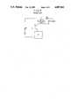
- FIG. 5shows a circuit diagram of a flyback converter type switching power source, in which the symbol B is a DC power source, T is a transformer, TR is a transistor, CT is a control circuit, D s is a diode, C s is a capacitor, and Z L is a load.
- the transistor TRswitches ON and OFF repetitively according to the control of the control circuit CT.
- the transistor TRWhen the transistor TR is in ON state, the current flows from the DC power source B, through the primary winding N p of the transformer T, the transistor TR, to the DC power source B. Then, the energy is stored in the transformer T when the transistor TR is in ON state.
- That energy stored in the transformer Tis proportional to 1/2LI 2 , where L is inductance of the primary winding N p , and I is current in the primary winding N p .
- Linductance of the primary winding N p
- Icurrent in the primary winding N p .
- the inductance Lis too large, the current I would be small, and the stored energy would be small. Similarly, if the inductance is too small, the stored energy would also be small although the current I is large.
- a transformer for a flyback converter type switching power sourcehas an air gap in a magnetic path for reducing or having proper inductance.
- a pair of E-shaped ferrite cores 1abutted each other, an air gap G provided in a center leg of the core, and a bobbin with a winding on said center leg 2.
- the air gap Gis essential in a transformer of a flyback converter type switching power source for storing electro-magnetic energy.
- the transformer as shown in Fig. 3 in which an air gap G is provided at the center portion of the center leg 2has the disadvantage that leakage flux ⁇ which leaks from said air gap G interlinks with a winding 3 as shown in FIG. 4, and the winding 3 is subject to eddy current loss. Therefore, the temperature of the winding 3 is raised partially. That disadvantage is serious when the capacity of the transformer is large, like a transformer for a switching power source.
- the object of the present inventionis to overcome the disadvantages and limitations of a prior pulse transformer by providing a new and improved pulse transformer.
- a high frequency pulse transformerhaving a ferrite core (10,11) having a pair of side legs (10a11a) and a center leg (l0b, 11b) which is shorter than said side leg, so that a gap G is provided on the center leg, and an arm (10c, 11c) connecting said side legs with said center leg; a bobbin (15) having a cylindrical hollow center body (15a) and a pair of flanges (15b), having windings on said hollow center body, assembled with said ferrite core so that said center leg is inserted into the hollow center body of the bobbin; said gap G being located at end of said center leg (10a) under one of the extreme ends of said hollow center body of the bobbin (15); and no coil means (16a, 16b) being provided for allowing no winding in a predetermined length from said gap.
- said no coil meansis a belt provided at the end of the hollow center body of the bobbin.
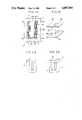
- FIG. 1Ais a cross sectional view of a high frequency pulse transformer according to the present invention
- FIG. 1Bis a perspective view of a bobbin of the transformer of FIG. 1A
- FIGS. 2A, 2B and 2Cshow perspective views of a core for explaining manufacturing process of the core of the present transformer
- FIG. 3shows a core of a prior pulse transformer
- FIG. 4is an enlarged partial view of a prior pulse transformer which has a winding
- FIG. 5is a circuit diagram of a prior flyback converter type switching power source.
- FIG. 1shows a cross section of the high frequency pulse transformer according to the present invention
- FIGS. 2A through 2Cshow the producing steps of a core of the transformer.
- the numeral 10is an E-shaped ferrite core having a pair of long side legs 10a, a long center leg 10b, and an arm 10c coupling the side legs 10a with the center leg 10b.
- the numeral 11is a second E-shaped ferrite core having a pair of short side legs 11a, a short center leg 11b, and an arm 11c coupling the side legs 11a with the center leg 11b.
- the first E-shaped core 10 and the second E-shaped core 11are manufactured as shown in FIGS. 2A through 2C.
- a closed ferrite core having a pair of windows as shown by the numeral 13 in FIG. 2Ais shaped and sintered.
- the core 13is separated to two portions 10' and 11' as shown in FIG. 2B by cutting the core 13 along the line X so that a pair of asymmetrical E-shaped cores are obtained.
- the center leg of one of the E-shaped coresis ground so that the center leg becomes shorter than the side legs by removing the portion Y as shown in FIG. 2C. It is a matter of design choice whether the center leg of the E-shaped core with the longer side legs (and the center leg) is ground as shown in FIG. 2C, or the center leg of the E-shaped core with the shorter side legs is ground.
- a bobbin 15has a cylindrical hollow body 15a and a pair of flanges 15b at the ends of the body 15a.
- the center body 15ahas a pair of belts 16a and 16b at the extreme ends of the body 15a, so that the center body 15a is thicker at the ends than other portion of the center body l5a of the bobbin 15.
- a primary winding 17 of the transformeris wound on the non-thicked portion of the bobbin 15 (a primary winding 17 is not wound on the belts 16a and 16b).
- a secondary winding 18 of the transformeris wound on the primary winding 17 and the belts 16a and 16b through the insulation layer 19.
- the pair of E-shaped cores 10 and 11, and the bobbin 15 with the windingsare assembled together, so that the center leg 11b of the E-shaped core 10 is inserted into the hollow body 15a of the bobbin 15, and the side legs 10a of the E-shaped core 10 touches with the side legs 11a of the other E-shaped core 11.
- an air gap Gis provided between the center legs 10b and 11b of the pair of E-shaped cores 10 and 11, and that said air gap G is positioned under the belt 16b where no primary winding is provided.
- the insulation breakdown due to a partial over heatis prevented, and the operational reliability of a transformer is improved.
- the insulation material for a lower temperature standardmay be used for the present transformer (for instance, B type 130° C. insulation material for a prior transformer may be replaced by A type 105° C. insulation material in the present invention).
- the size of a transformer and/or a ferrite coremay be smaller than in the prior art.
- the combination of an E-shaped core and an I-shaped coreis of course possible in the present invention, although the embodiment describes the combination of a pair of E-shaped cores.
- the cross section of a center legmay either be rectangular, or circular.
Landscapes
- Engineering & Computer Science (AREA)
- Power Engineering (AREA)
- Coils Or Transformers For Communication (AREA)
Abstract
Description
The present invention relates to a high frequency pulse transformer which has an air gap along a magnetic path by a ferrite core, and in particular, relates to such a transformer which is used for voltage conversion in a switching power source of a flyback converter type.
FIG. 5 shows a circuit diagram of a flyback converter type switching power source, in which the symbol B is a DC power source, T is a transformer, TR is a transistor, CT is a control circuit, Ds is a diode, Cs is a capacitor, and ZL is a load. The transistor TR switches ON and OFF repetitively according to the control of the control circuit CT. When the transistor TR is in ON state, the current flows from the DC power source B, through the primary winding Np of the transformer T, the transistor TR, to the DC power source B. Then, the energy is stored in the transformer T when the transistor TR is in ON state. That energy stored in the transformer T is proportional to 1/2LI2, where L is inductance of the primary winding Np, and I is current in the primary winding Np. Next, when the transistor is in OFF state, that energy is released to the load ZL through the diode Ds and the capacitor Cs which functions as a rectifier and a smoother. Therefore, the inductance L of the primary winding must have the proper value so that a lot of energy is stored in the transformer during the ON state of the transistor, although an usual transformer for voltage conversion has inductance as large as possible.
If the inductance L is too large, the current I would be small, and the stored energy would be small. Similarly, if the inductance is too small, the stored energy would also be small although the current I is large.
Therefore, it is preferable that a transformer for a flyback converter type switching power source has an air gap in a magnetic path for reducing or having proper inductance.
We first tried this kind of high frequency pulse transformer for switching power source, as shown in Fig. 3, in which a pair of E-shaped ferrite cores 1 abutted each other, an air gap G provided in a center leg of the core, and a bobbin with a winding on saidcenter leg 2. The air gap G is essential in a transformer of a flyback converter type switching power source for storing electro-magnetic energy.
However, we found that the transformer as shown in Fig. 3 in which an air gap G is provided at the center portion of thecenter leg 2 has the disadvantage that leakage flux φ which leaks from said air gap G interlinks with a winding 3 as shown in FIG. 4, and the winding 3 is subject to eddy current loss. Therefore, the temperature of the winding 3 is raised partially. That disadvantage is serious when the capacity of the transformer is large, like a transformer for a switching power source.
The object of the present invention is to overcome the disadvantages and limitations of a prior pulse transformer by providing a new and improved pulse transformer.
It is also an object of the present invention to provide a pulse transformer which is free from eddy current loss in a winding by the presence of an air gap, so that the partial high temperature is prevented, and the power efficiency of the transformer is improved.
The above and other objects are attained by a high frequency pulse transformer having a ferrite core (10,11) having a pair of side legs (10a11a) and a center leg (l0b, 11b) which is shorter than said side leg, so that a gap G is provided on the center leg, and an arm (10c, 11c) connecting said side legs with said center leg; a bobbin (15) having a cylindrical hollow center body (15a) and a pair of flanges (15b), having windings on said hollow center body, assembled with said ferrite core so that said center leg is inserted into the hollow center body of the bobbin; said gap G being located at end of said center leg (10a) under one of the extreme ends of said hollow center body of the bobbin (15); and no coil means (16a, 16b) being provided for allowing no winding in a predetermined length from said gap.
Preferably, said no coil means is a belt provided at the end of the hollow center body of the bobbin.
The foregoing and other objects, features, and attendant advantages of the present invention will be appreciated as the same become better understood by means of the following description and accompanying drawings wherein;
FIG. 1A is a cross sectional view of a high frequency pulse transformer according to the present invention,
FIG. 1B is a perspective view of a bobbin of the transformer of FIG. 1A,
FIGS. 2A, 2B and 2C show perspective views of a core for explaining manufacturing process of the core of the present transformer,
FIG. 3 shows a core of a prior pulse transformer,
FIG. 4 is an enlarged partial view of a prior pulse transformer which has a winding, and
FIG. 5 is a circuit diagram of a prior flyback converter type switching power source.
FIG. 1 shows a cross section of the high frequency pulse transformer according to the present invention, and FIGS. 2A through 2C show the producing steps of a core of the transformer.
In FIG. 1, thenumeral 10 is an E-shaped ferrite core having a pair oflong side legs 10a, along center leg 10b, and an arm 10c coupling theside legs 10a with thecenter leg 10b. Thenumeral 11 is a second E-shaped ferrite core having a pair ofshort side legs 11a, ashort center leg 11b, and an arm 11c coupling theside legs 11a with thecenter leg 11b.
The first E-shapedcore 10 and thesecond E-shaped core 11 are manufactured as shown in FIGS. 2A through 2C. First, a closed ferrite core having a pair of windows as shown by thenumeral 13 in FIG. 2A is shaped and sintered. Next, thecore 13 is separated to two portions 10' and 11' as shown in FIG. 2B by cutting thecore 13 along the line X so that a pair of asymmetrical E-shaped cores are obtained. Next, the center leg of one of the E-shaped cores is ground so that the center leg becomes shorter than the side legs by removing the portion Y as shown in FIG. 2C. It is a matter of design choice whether the center leg of the E-shaped core with the longer side legs (and the center leg) is ground as shown in FIG. 2C, or the center leg of the E-shaped core with the shorter side legs is ground.
Abobbin 15 has a cylindricalhollow body 15a and a pair offlanges 15b at the ends of thebody 15a. Thecenter body 15a has a pair ofbelts body 15a, so that thecenter body 15a is thicker at the ends than other portion of the center body l5a of thebobbin 15.
Aprimary winding 17 of the transformer is wound on the non-thicked portion of the bobbin 15 (aprimary winding 17 is not wound on thebelts secondary winding 18 of the transformer is wound on the primary winding 17 and thebelts insulation layer 19.
The pair of E-shapedcores bobbin 15 with the windings are assembled together, so that thecenter leg 11b of theE-shaped core 10 is inserted into thehollow body 15a of thebobbin 15, and theside legs 10a of theE-shaped core 10 touches with theside legs 11a of theother E-shaped core 11. It should be noted that an air gap G is provided between thecenter legs E-shaped cores belt 16b where no primary winding is provided.
Therefore, even if a leakage flux exists around the air gap G, the leakage flux around the air gap G does not interlink with the primary winding nor the secondary winding because of the presence of thebelt 16b on thebobbin 15. Therefore, no eddy current loss because of the leakage flux occurs in the windings, and so, the partial high temperature in the windings is prevented.
Accordingly, the insulation breakdown due to a partial over heat is prevented, and the operational reliability of a transformer is improved. Further, the insulation material for a lower temperature standard may be used for the present transformer (for instance, B type 130° C. insulation material for a prior transformer may be replaced by A type 105° C. insulation material in the present invention).
Further, because of the lack of eddy current loss, the conversion efficiency of a transformer is improved. Therefore, the size of a transformer and/or a ferrite core may be smaller than in the prior art.
As a modification, the combination of an E-shaped core and an I-shaped core is of course possible in the present invention, although the embodiment describes the combination of a pair of E-shaped cores. Further, the cross section of a center leg may either be rectangular, or circular.
From the foregoing it will now be apparent that a new and improved transformer has been discovered. It should be understood of course that the embodiments disclosed are merely illustrative and are not intended to limit the scope of the invention. Reference should be made to the appended claims, therefore, rather than the specification as indicating the scope of the invention.
Claims (5)
1. A transformer for a flyback converter type switching power source comprising;
a ferrite core (10,11) having a pair of side legs (10a, 11a) and a center leg (10b, 11b) which is shorter than said side legs, so that a gap G is provided on the center leg, and arms (10c, 11c) connecting said side legs with said center leg,
a bobbin (15) having a cylindrical hollow center body (15a) and a pair of flanges (15b), having windings on said hollow center body, assembled with said ferrite core so that said center leg is inserted into the hollow center body of the bobbin,
said gap G being located at end of said center leg (10a) under one of the extreme ends of said hollow center body of the bobbin (15), and
no coil means (16a, 16b) being provided for allowing no winding in predetermined axial and radial lengths from said gap.
2. A transformer according to claim 1, wherein said no coil means is a belt provided at the end of said hollow center body of said bobbin.
3. A transformer according to claim 1, wherein said ferrite core is a combination of a pair of E-shaped cores.
4. A transformer according to claim 1, wherein said ferrite core is combination of an E-shaped core and an I-shaped core.
5. A transformer according to claim 2, wherein a primary winding is provided on non-belt portion of the hollow center body, and a secondary winding is provided on the whole length of the hollow center body through an insulation layer on the primary winding.
Applications Claiming Priority (2)
| Application Number | Priority Date | Filing Date | Title |
|---|---|---|---|
| JP1988003819UJPH01108917U (en) | 1988-01-18 | 1988-01-18 | |
| JP63-3819[U] | 1988-01-18 |
Publications (1)
| Publication Number | Publication Date |
|---|---|
| US4887061Atrue US4887061A (en) | 1989-12-12 |
Family
ID=11567801
Family Applications (1)
| Application Number | Title | Priority Date | Filing Date |
|---|---|---|---|
| US07/292,007Expired - Fee RelatedUS4887061A (en) | 1988-01-18 | 1988-12-30 | Transformer for a flyback type converter |
Country Status (2)
| Country | Link |
|---|---|
| US (1) | US4887061A (en) |
| JP (1) | JPH01108917U (en) |
Cited By (60)
| Publication number | Priority date | Publication date | Assignee | Title |
|---|---|---|---|---|
| GB2245106A (en)* | 1990-05-29 | 1991-12-18 | Murata Manufacturing Co | Gapped flyback smps transformer core with gap faces of reduced area |
| WO1992017892A1 (en)* | 1991-04-01 | 1992-10-15 | Motorola Lighting, Inc. | Inductor |
| US5378966A (en)* | 1992-12-16 | 1995-01-03 | Ncr Corporation | Flux captivated emission controlled flyback transformer |
| US5418513A (en)* | 1991-04-03 | 1995-05-23 | Stanley Electric Co. Ltd. | Transformer core in transformer circuit |
| US5748064A (en)* | 1996-02-22 | 1998-05-05 | Northrop Grumman Corporation | Low profile reactor |
| EP0918342A4 (en)* | 1997-06-13 | 2000-08-16 | Samwha Tecom Co Ltd | Slit transformer |
| US6211765B1 (en)* | 1990-02-27 | 2001-04-03 | Tdk Corporation | Coil device |
| US6608473B2 (en)* | 2000-11-09 | 2003-08-19 | Robert Bosch Gmbh | Electrical machine, especially a three-phase generator |
| US6696913B2 (en)* | 2000-11-17 | 2004-02-24 | Epcos Ag | Ferrite core for a transformer |
| US20060097837A1 (en)* | 2004-07-15 | 2006-05-11 | Matsushita Electric Industrial Co., Ltd. | Coil component |
| US20070139151A1 (en)* | 2005-12-19 | 2007-06-21 | Nussbaum Michael B | Amplifier output filter having planar inductor |
| US20070159289A1 (en)* | 2006-01-06 | 2007-07-12 | Jin-Hyung Lee | Magnetic core, and inductor and transformer comprising the same |
| US7271691B2 (en)* | 2001-03-31 | 2007-09-18 | Lg.Philips Lcd Co., Ltd. | Method of winding coil and transformer and inverter liquid crystal display having coil wound using the same |
| US7280026B2 (en)* | 2002-04-18 | 2007-10-09 | Coldwatt, Inc. | Extended E matrix integrated magnetics (MIM) core |
| US7298118B2 (en) | 2005-02-23 | 2007-11-20 | Coldwatt, Inc. | Power converter employing a tapped inductor and integrated magnetics and method of operating the same |
| US7321283B2 (en) | 2004-08-19 | 2008-01-22 | Coldwatt, Inc. | Vertical winding structures for planar magnetic switched-mode power converters |
| US7385375B2 (en) | 2005-02-23 | 2008-06-10 | Coldwatt, Inc. | Control circuit for a depletion mode switch and method of operating the same |
| US20080192960A1 (en)* | 2007-02-09 | 2008-08-14 | Nussbaum Michael B | Hybrid Filter for Audio Switching Amplifier |
| US7417875B2 (en) | 2005-02-08 | 2008-08-26 | Coldwatt, Inc. | Power converter employing integrated magnetics with a current multiplier rectifier and method of operating the same |
| US7427910B2 (en) | 2004-08-19 | 2008-09-23 | Coldwatt, Inc. | Winding structure for efficient switch-mode power converters |
| US20090045682A1 (en)* | 2007-08-13 | 2009-02-19 | Anadish Kumar Pal | Stacked rail stator and capacitive armature linear motor |
| US7667986B2 (en) | 2006-12-01 | 2010-02-23 | Flextronics International Usa, Inc. | Power system with power converters having an adaptive controller |
| US7675759B2 (en) | 2006-12-01 | 2010-03-09 | Flextronics International Usa, Inc. | Power system with power converters having an adaptive controller |
| US7675758B2 (en) | 2006-12-01 | 2010-03-09 | Flextronics International Usa, Inc. | Power converter with an adaptive controller and method of operating the same |
| US20100289607A1 (en)* | 2009-05-15 | 2010-11-18 | Delta Electronics, Inc. | Transformer structure |
| US7876191B2 (en) | 2005-02-23 | 2011-01-25 | Flextronics International Usa, Inc. | Power converter employing a tapped inductor and integrated magnetics and method of operating the same |
| US7889517B2 (en) | 2006-12-01 | 2011-02-15 | Flextronics International Usa, Inc. | Power system with power converters having an adaptive controller |
| US7906941B2 (en) | 2007-06-19 | 2011-03-15 | Flextronics International Usa, Inc. | System and method for estimating input power for a power processing circuit |
| US8125205B2 (en) | 2006-08-31 | 2012-02-28 | Flextronics International Usa, Inc. | Power converter employing regulators with a coupled inductor |
| US8212643B1 (en) | 2008-07-09 | 2012-07-03 | Universal Lighting Technologies, Inc. | Bobbin for an inductive electronic component |
| CN102568752A (en)* | 2011-12-27 | 2012-07-11 | 华为技术有限公司 | Inductive member and electronic device with the inductive member |
| CN102592782A (en)* | 2012-03-14 | 2012-07-18 | 北京七星飞行电子有限公司 | Choking coil and manufacture method thereof |
| US8502520B2 (en) | 2007-03-14 | 2013-08-06 | Flextronics International Usa, Inc | Isolated power converter |
| US8514593B2 (en) | 2009-06-17 | 2013-08-20 | Power Systems Technologies, Ltd. | Power converter employing a variable switching frequency and a magnetic device with a non-uniform gap |
| US8520420B2 (en) | 2009-12-18 | 2013-08-27 | Power Systems Technologies, Ltd. | Controller for modifying dead time between switches in a power converter |
| US8520414B2 (en) | 2009-01-19 | 2013-08-27 | Power Systems Technologies, Ltd. | Controller for a power converter |
| US8638578B2 (en) | 2009-08-14 | 2014-01-28 | Power System Technologies, Ltd. | Power converter including a charge pump employable in a power adapter |
| US8643222B2 (en) | 2009-06-17 | 2014-02-04 | Power Systems Technologies Ltd | Power adapter employing a power reducer |
| US8767418B2 (en) | 2010-03-17 | 2014-07-01 | Power Systems Technologies Ltd. | Control system for a power converter and method of operating the same |
| US8787043B2 (en) | 2010-01-22 | 2014-07-22 | Power Systems Technologies, Ltd. | Controller for a power converter and method of operating the same |
| US8792256B2 (en) | 2012-01-27 | 2014-07-29 | Power Systems Technologies Ltd. | Controller for a switch and method of operating the same |
| US8792257B2 (en) | 2011-03-25 | 2014-07-29 | Power Systems Technologies, Ltd. | Power converter with reduced power dissipation |
| US20140266535A1 (en)* | 2013-03-14 | 2014-09-18 | Hiq Solar, Inc. | Low loss inductor with offset gap and windings |
| US8976549B2 (en) | 2009-12-03 | 2015-03-10 | Power Systems Technologies, Ltd. | Startup circuit including first and second Schmitt triggers and power converter employing the same |
| US9019061B2 (en) | 2009-03-31 | 2015-04-28 | Power Systems Technologies, Ltd. | Magnetic device formed with U-shaped core pieces and power converter employing the same |
| US9077248B2 (en) | 2009-06-17 | 2015-07-07 | Power Systems Technologies Ltd | Start-up circuit for a power adapter |
| US9088216B2 (en) | 2009-01-19 | 2015-07-21 | Power Systems Technologies, Ltd. | Controller for a synchronous rectifier switch |
| US9099232B2 (en) | 2012-07-16 | 2015-08-04 | Power Systems Technologies Ltd. | Magnetic device and power converter employing the same |
| US9106130B2 (en) | 2012-07-16 | 2015-08-11 | Power Systems Technologies, Inc. | Magnetic device and power converter employing the same |
| US9190898B2 (en) | 2012-07-06 | 2015-11-17 | Power Systems Technologies, Ltd | Controller for a power converter and method of operating the same |
| US9197132B2 (en) | 2006-12-01 | 2015-11-24 | Flextronics International Usa, Inc. | Power converter with an adaptive controller and method of operating the same |
| US9214264B2 (en) | 2012-07-16 | 2015-12-15 | Power Systems Technologies, Ltd. | Magnetic device and power converter employing the same |
| US9240712B2 (en) | 2012-12-13 | 2016-01-19 | Power Systems Technologies Ltd. | Controller including a common current-sense device for power switches of a power converter |
| US9246391B2 (en) | 2010-01-22 | 2016-01-26 | Power Systems Technologies Ltd. | Controller for providing a corrected signal to a sensed peak current through a circuit element of a power converter |
| US9300206B2 (en) | 2013-11-15 | 2016-03-29 | Power Systems Technologies Ltd. | Method for estimating power of a power converter |
| US9379629B2 (en) | 2012-07-16 | 2016-06-28 | Power Systems Technologies, Ltd. | Magnetic device and power converter employing the same |
| CN107068321A (en)* | 2017-06-22 | 2017-08-18 | 太仓市变压器有限公司 | A kind of magnetic core for transformer |
| CN107276058A (en)* | 2017-06-05 | 2017-10-20 | 西安交通大学 | A kind of induced field current shift module and its electric current transfer method |
| US9991045B1 (en)* | 2014-11-04 | 2018-06-05 | Universal Lighting Technologies, Inc. | Bobbin and core assembly configuration and method for E-core and I-core combination |
| CN113674972A (en)* | 2020-05-14 | 2021-11-19 | Tdk株式会社 | Coil device |
Citations (2)
| Publication number | Priority date | Publication date | Assignee | Title |
|---|---|---|---|---|
| US1876451A (en)* | 1932-09-06 | r gurtler | ||
| US4009460A (en)* | 1974-09-24 | 1977-02-22 | Hitachi Metals, Ltd. | Inductor |
- 1988
- 1988-01-18JPJP1988003819Upatent/JPH01108917U/jaactivePending
- 1988-12-30USUS07/292,007patent/US4887061A/ennot_activeExpired - Fee Related
Patent Citations (2)
| Publication number | Priority date | Publication date | Assignee | Title |
|---|---|---|---|---|
| US1876451A (en)* | 1932-09-06 | r gurtler | ||
| US4009460A (en)* | 1974-09-24 | 1977-02-22 | Hitachi Metals, Ltd. | Inductor |
Cited By (73)
| Publication number | Priority date | Publication date | Assignee | Title |
|---|---|---|---|---|
| US6211765B1 (en)* | 1990-02-27 | 2001-04-03 | Tdk Corporation | Coil device |
| GB2245106A (en)* | 1990-05-29 | 1991-12-18 | Murata Manufacturing Co | Gapped flyback smps transformer core with gap faces of reduced area |
| WO1992017892A1 (en)* | 1991-04-01 | 1992-10-15 | Motorola Lighting, Inc. | Inductor |
| US5418513A (en)* | 1991-04-03 | 1995-05-23 | Stanley Electric Co. Ltd. | Transformer core in transformer circuit |
| US5378966A (en)* | 1992-12-16 | 1995-01-03 | Ncr Corporation | Flux captivated emission controlled flyback transformer |
| US5748064A (en)* | 1996-02-22 | 1998-05-05 | Northrop Grumman Corporation | Low profile reactor |
| EP0918342A4 (en)* | 1997-06-13 | 2000-08-16 | Samwha Tecom Co Ltd | Slit transformer |
| US6608473B2 (en)* | 2000-11-09 | 2003-08-19 | Robert Bosch Gmbh | Electrical machine, especially a three-phase generator |
| US6696913B2 (en)* | 2000-11-17 | 2004-02-24 | Epcos Ag | Ferrite core for a transformer |
| US7271691B2 (en)* | 2001-03-31 | 2007-09-18 | Lg.Philips Lcd Co., Ltd. | Method of winding coil and transformer and inverter liquid crystal display having coil wound using the same |
| US7280026B2 (en)* | 2002-04-18 | 2007-10-09 | Coldwatt, Inc. | Extended E matrix integrated magnetics (MIM) core |
| US7633369B2 (en)* | 2002-04-18 | 2009-12-15 | Flextronics International Usa, Inc. | Extended E matrix integrated magnetics (MIM) core |
| US8134443B2 (en) | 2002-04-18 | 2012-03-13 | Flextronics International Usa, Inc. | Extended E matrix integrated magnetics (MIM) core |
| US20080024259A1 (en)* | 2002-04-18 | 2008-01-31 | Sriram Chandrasekaran | Extended E Matrix Integrated Magnetics (MIM) Core |
| US7268657B2 (en)* | 2004-07-15 | 2007-09-11 | Matsushita Electric Industrial Co., Ltd | Coil component |
| US20060097837A1 (en)* | 2004-07-15 | 2006-05-11 | Matsushita Electric Industrial Co., Ltd. | Coil component |
| US7321283B2 (en) | 2004-08-19 | 2008-01-22 | Coldwatt, Inc. | Vertical winding structures for planar magnetic switched-mode power converters |
| US7427910B2 (en) | 2004-08-19 | 2008-09-23 | Coldwatt, Inc. | Winding structure for efficient switch-mode power converters |
| US7554430B2 (en) | 2004-08-19 | 2009-06-30 | Flextronics International Usa, Inc. | Vertical winding structures for planar magnetic switched-mode power converters |
| US7675764B2 (en) | 2005-02-08 | 2010-03-09 | Flextronics International Usa, Inc. | Power converter employing integrated magnetics with a current multiplier rectifier and method of operating the same |
| US7417875B2 (en) | 2005-02-08 | 2008-08-26 | Coldwatt, Inc. | Power converter employing integrated magnetics with a current multiplier rectifier and method of operating the same |
| US7298118B2 (en) | 2005-02-23 | 2007-11-20 | Coldwatt, Inc. | Power converter employing a tapped inductor and integrated magnetics and method of operating the same |
| US7385375B2 (en) | 2005-02-23 | 2008-06-10 | Coldwatt, Inc. | Control circuit for a depletion mode switch and method of operating the same |
| US7876191B2 (en) | 2005-02-23 | 2011-01-25 | Flextronics International Usa, Inc. | Power converter employing a tapped inductor and integrated magnetics and method of operating the same |
| US7432793B2 (en) | 2005-12-19 | 2008-10-07 | Bose Corporation | Amplifier output filter having planar inductor |
| US20070139151A1 (en)* | 2005-12-19 | 2007-06-21 | Nussbaum Michael B | Amplifier output filter having planar inductor |
| US20070159289A1 (en)* | 2006-01-06 | 2007-07-12 | Jin-Hyung Lee | Magnetic core, and inductor and transformer comprising the same |
| US8125205B2 (en) | 2006-08-31 | 2012-02-28 | Flextronics International Usa, Inc. | Power converter employing regulators with a coupled inductor |
| US7675758B2 (en) | 2006-12-01 | 2010-03-09 | Flextronics International Usa, Inc. | Power converter with an adaptive controller and method of operating the same |
| US9197132B2 (en) | 2006-12-01 | 2015-11-24 | Flextronics International Usa, Inc. | Power converter with an adaptive controller and method of operating the same |
| US7667986B2 (en) | 2006-12-01 | 2010-02-23 | Flextronics International Usa, Inc. | Power system with power converters having an adaptive controller |
| US7889517B2 (en) | 2006-12-01 | 2011-02-15 | Flextronics International Usa, Inc. | Power system with power converters having an adaptive controller |
| US8477514B2 (en) | 2006-12-01 | 2013-07-02 | Flextronics International Usa, Inc. | Power system with power converters having an adaptive controller |
| US7675759B2 (en) | 2006-12-01 | 2010-03-09 | Flextronics International Usa, Inc. | Power system with power converters having an adaptive controller |
| US20080192960A1 (en)* | 2007-02-09 | 2008-08-14 | Nussbaum Michael B | Hybrid Filter for Audio Switching Amplifier |
| US8502520B2 (en) | 2007-03-14 | 2013-08-06 | Flextronics International Usa, Inc | Isolated power converter |
| US7906941B2 (en) | 2007-06-19 | 2011-03-15 | Flextronics International Usa, Inc. | System and method for estimating input power for a power processing circuit |
| US20090045682A1 (en)* | 2007-08-13 | 2009-02-19 | Anadish Kumar Pal | Stacked rail stator and capacitive armature linear motor |
| US7830059B2 (en)* | 2007-08-13 | 2010-11-09 | Anadish Kumar Pal | Stacked rail stator and capacitive armature linear motor |
| US8212643B1 (en) | 2008-07-09 | 2012-07-03 | Universal Lighting Technologies, Inc. | Bobbin for an inductive electronic component |
| US8520414B2 (en) | 2009-01-19 | 2013-08-27 | Power Systems Technologies, Ltd. | Controller for a power converter |
| US9088216B2 (en) | 2009-01-19 | 2015-07-21 | Power Systems Technologies, Ltd. | Controller for a synchronous rectifier switch |
| US9019061B2 (en) | 2009-03-31 | 2015-04-28 | Power Systems Technologies, Ltd. | Magnetic device formed with U-shaped core pieces and power converter employing the same |
| US8188825B2 (en)* | 2009-05-15 | 2012-05-29 | Delta Electronics, Inc. | Transformer structure |
| US20100289607A1 (en)* | 2009-05-15 | 2010-11-18 | Delta Electronics, Inc. | Transformer structure |
| US8643222B2 (en) | 2009-06-17 | 2014-02-04 | Power Systems Technologies Ltd | Power adapter employing a power reducer |
| US8514593B2 (en) | 2009-06-17 | 2013-08-20 | Power Systems Technologies, Ltd. | Power converter employing a variable switching frequency and a magnetic device with a non-uniform gap |
| US9077248B2 (en) | 2009-06-17 | 2015-07-07 | Power Systems Technologies Ltd | Start-up circuit for a power adapter |
| US8638578B2 (en) | 2009-08-14 | 2014-01-28 | Power System Technologies, Ltd. | Power converter including a charge pump employable in a power adapter |
| US8976549B2 (en) | 2009-12-03 | 2015-03-10 | Power Systems Technologies, Ltd. | Startup circuit including first and second Schmitt triggers and power converter employing the same |
| US8520420B2 (en) | 2009-12-18 | 2013-08-27 | Power Systems Technologies, Ltd. | Controller for modifying dead time between switches in a power converter |
| US8787043B2 (en) | 2010-01-22 | 2014-07-22 | Power Systems Technologies, Ltd. | Controller for a power converter and method of operating the same |
| US9246391B2 (en) | 2010-01-22 | 2016-01-26 | Power Systems Technologies Ltd. | Controller for providing a corrected signal to a sensed peak current through a circuit element of a power converter |
| US8767418B2 (en) | 2010-03-17 | 2014-07-01 | Power Systems Technologies Ltd. | Control system for a power converter and method of operating the same |
| US8792257B2 (en) | 2011-03-25 | 2014-07-29 | Power Systems Technologies, Ltd. | Power converter with reduced power dissipation |
| CN102568752A (en)* | 2011-12-27 | 2012-07-11 | 华为技术有限公司 | Inductive member and electronic device with the inductive member |
| CN102568752B (en)* | 2011-12-27 | 2014-01-08 | 华为技术有限公司 | Inductive component and electronic equipment with the same |
| US8792256B2 (en) | 2012-01-27 | 2014-07-29 | Power Systems Technologies Ltd. | Controller for a switch and method of operating the same |
| CN102592782A (en)* | 2012-03-14 | 2012-07-18 | 北京七星飞行电子有限公司 | Choking coil and manufacture method thereof |
| CN102592782B (en)* | 2012-03-14 | 2013-09-25 | 北京七星飞行电子有限公司 | Choking coil and manufacture method thereof |
| US9190898B2 (en) | 2012-07-06 | 2015-11-17 | Power Systems Technologies, Ltd | Controller for a power converter and method of operating the same |
| US9099232B2 (en) | 2012-07-16 | 2015-08-04 | Power Systems Technologies Ltd. | Magnetic device and power converter employing the same |
| US9106130B2 (en) | 2012-07-16 | 2015-08-11 | Power Systems Technologies, Inc. | Magnetic device and power converter employing the same |
| US9214264B2 (en) | 2012-07-16 | 2015-12-15 | Power Systems Technologies, Ltd. | Magnetic device and power converter employing the same |
| US9379629B2 (en) | 2012-07-16 | 2016-06-28 | Power Systems Technologies, Ltd. | Magnetic device and power converter employing the same |
| US9240712B2 (en) | 2012-12-13 | 2016-01-19 | Power Systems Technologies Ltd. | Controller including a common current-sense device for power switches of a power converter |
| US20140266535A1 (en)* | 2013-03-14 | 2014-09-18 | Hiq Solar, Inc. | Low loss inductor with offset gap and windings |
| US9300206B2 (en) | 2013-11-15 | 2016-03-29 | Power Systems Technologies Ltd. | Method for estimating power of a power converter |
| US9991045B1 (en)* | 2014-11-04 | 2018-06-05 | Universal Lighting Technologies, Inc. | Bobbin and core assembly configuration and method for E-core and I-core combination |
| CN107276058A (en)* | 2017-06-05 | 2017-10-20 | 西安交通大学 | A kind of induced field current shift module and its electric current transfer method |
| CN107276058B (en)* | 2017-06-05 | 2019-12-03 | 西安交通大学 | A kind of induced field current shift module and its electric current transfer method |
| CN107068321A (en)* | 2017-06-22 | 2017-08-18 | 太仓市变压器有限公司 | A kind of magnetic core for transformer |
| CN113674972A (en)* | 2020-05-14 | 2021-11-19 | Tdk株式会社 | Coil device |
Also Published As
| Publication number | Publication date |
|---|---|
| JPH01108917U (en) | 1989-07-24 |
Similar Documents
| Publication | Publication Date | Title |
|---|---|---|
| US4887061A (en) | Transformer for a flyback type converter | |
| US4473811A (en) | Single bobbin transformer having multiple delink windings and method of making same | |
| US5619400A (en) | Magnetic core structures and construction techniques therefor | |
| US4047138A (en) | Power inductor and transformer with low acoustic noise air gap | |
| US20130343091A1 (en) | Integrated magnetics for soft switching converter | |
| US5506559A (en) | Choke coil for eliminating common mode noise and normal mode noise | |
| US4635019A (en) | Coil apparatus with divided windings | |
| US20040125628A1 (en) | High-frequency power inductance element | |
| US4536734A (en) | Transformer winding sheet insulator with spacer member | |
| JP3161398B2 (en) | Converter transformer | |
| JP4258722B2 (en) | Reactor device | |
| JPH029109A (en) | high voltage transformer | |
| JPS6132506A (en) | Transformer | |
| US4851629A (en) | High-frequency heating device | |
| JP2003224012A (en) | Winding-type coil | |
| KR102698084B1 (en) | A nano-core assembly for transformer | |
| US20050270133A1 (en) | Transformer structure | |
| JPH075617Y2 (en) | Electromagnetic device | |
| JPS597204B2 (en) | High frequency transformer for high frequency switching power supply | |
| JPH0536538A (en) | Line filter transformer | |
| EP4621811A1 (en) | High power high current transformer | |
| JP2751228B2 (en) | Converter transformer | |
| JPH03126026U (en) | ||
| KR0130286Y1 (en) | High frequency voltage translator that can control leakage inductance | |
| JP2987646B2 (en) | Small transformer |
Legal Events
| Date | Code | Title | Description |
|---|---|---|---|
| AS | Assignment | Owner name:TDK CORPORATION, JAPAN Free format text:ASSIGNMENT OF ASSIGNORS INTEREST.;ASSIGNOR:MATSUMURA, TOMOYA;REEL/FRAME:005015/0303 Effective date:19881220 | |
| FPAY | Fee payment | Year of fee payment:4 | |
| REMI | Maintenance fee reminder mailed | ||
| LAPS | Lapse for failure to pay maintenance fees | ||
| FP | Lapsed due to failure to pay maintenance fee | Effective date:19971217 | |
| STCH | Information on status: patent discontinuation | Free format text:PATENT EXPIRED DUE TO NONPAYMENT OF MAINTENANCE FEES UNDER 37 CFR 1.362 |