US4886070A - Method of in vivo calibration of a pressure sensor - Google Patents
Method of in vivo calibration of a pressure sensorDownload PDFInfo
- Publication number
- US4886070A US4886070AUS07/192,604US19260488AUS4886070AUS 4886070 AUS4886070 AUS 4886070AUS 19260488 AUS19260488 AUS 19260488AUS 4886070 AUS4886070 AUS 4886070A
- Authority
- US
- United States
- Prior art keywords
- pressure
- value
- pressure sensor
- displayed
- responsive element
- Prior art date
- Legal status (The legal status is an assumption and is not a legal conclusion. Google has not performed a legal analysis and makes no representation as to the accuracy of the status listed.)
- Expired - Fee Related
Links
Images

Classifications
- A—HUMAN NECESSITIES
- A61—MEDICAL OR VETERINARY SCIENCE; HYGIENE
- A61B—DIAGNOSIS; SURGERY; IDENTIFICATION
- A61B5/00—Measuring for diagnostic purposes; Identification of persons
- A61B5/02—Detecting, measuring or recording for evaluating the cardiovascular system, e.g. pulse, heart rate, blood pressure or blood flow
- A61B5/021—Measuring pressure in heart or blood vessels
- A61B5/0215—Measuring pressure in heart or blood vessels by means inserted into the body
- A61B5/02156—Calibration means
- G—PHYSICS
- G01—MEASURING; TESTING
- G01L—MEASURING FORCE, STRESS, TORQUE, WORK, MECHANICAL POWER, MECHANICAL EFFICIENCY, OR FLUID PRESSURE
- G01L27/00—Testing or calibrating of apparatus for measuring fluid pressure
- G01L27/002—Calibrating, i.e. establishing true relation between transducer output value and value to be measured, zeroing, linearising or span error determination
- G—PHYSICS
- G01—MEASURING; TESTING
- G01L—MEASURING FORCE, STRESS, TORQUE, WORK, MECHANICAL POWER, MECHANICAL EFFICIENCY, OR FLUID PRESSURE
- G01L9/00—Measuring steady of quasi-steady pressure of fluid or fluent solid material by electric or magnetic pressure-sensitive elements; Transmitting or indicating the displacement of mechanical pressure-sensitive elements, used to measure the steady or quasi-steady pressure of a fluid or fluent solid material, by electric or magnetic means
- G01L9/0041—Transmitting or indicating the displacement of flexible diaphragms
- G01L9/0051—Transmitting or indicating the displacement of flexible diaphragms using variations in ohmic resistance
- G01L9/0052—Transmitting or indicating the displacement of flexible diaphragms using variations in ohmic resistance of piezoresistive elements
- G01L9/0055—Transmitting or indicating the displacement of flexible diaphragms using variations in ohmic resistance of piezoresistive elements bonded on a diaphragm
Definitions
- This inventionrelates to strain gage type pressure sensors and to methods of calibrating such sensors under in vivo conditions. More particularly, it relates to strain gage type pressure sensors which permit in vivo calibration of the zero-offset due to drift, and to a method employed in calibrating such pressure sensors for such drift.
- Miniature pressure sensors or transducers mounted at the distal end of cathetersare commonly used to measure internal blood pressure in patients.
- the pressure sensor and catheterare inserted into the subject and positioned at a measurement site of interest.
- Such invasive pressure sensorsprovide high quality signals which permit very accurate determinations of the location and extent of such problems as heart valve malformations and malfunctions.
- the present pressure sensor inventionrepresents an improvement over the temperature-compensated and other types of pressure sensors disclosed in the aforementioned U.S. patents. It will be described in connection with a temperature-compensated pressure sensor of the type disclosed in U.S. Pat. No. 4,554,927 to Fussell, the disclosure of which patent is incorporated herein by reference. The Fussell patent is assigned to the assignee of the present invention.
- the typical prior art pressure sensorincludes a housing having an internal chamber. It also includes a pressure responsive element having inner and outer portions exposed respectively to atmospheric pressure conditions in the internal chamber and to ambient pressure conditions outside of the housing. In addition, a piezoresistive element is positioned in the internal chamber, and means are provided to couple the pressure responsive element to the piezoresistive element so that pressure changes outside of the housing are reflected by resistance changes in the piezoresistive element.
- the pressure sensoralso includes a reference piezoresistance element which provides some level of temperature compensation, and compensating electrical circuitry is provided to accommodate differences in thermal coefficients of expansion which may affect the pressure responsive and temperature responsive piezoresistive elements differently.
- An additional object of the present inventionis to provide a method of recalibrating a pressure sensor while it is located in an in vivo measurement site.
- An improved pressure sensorcomprises a housing having an internal chamber adapted to be connected to a conduit means for varying the pressure therein; a piezoresistive element positioned in the chamber and adapted to be connected to circuit means for sensing changes in the resistance of the piezoresistive element; a pressure responsive element carried by the housing and having an inner portion and an outer portion, the inner portion being exposed to the pressure extant in the internal chamber and the outer portion being exposed to ambient pressure conditions outside of the housing; and means coupling the pressure responsive element to the piezoresistive element in such a manner that when equal pressures are concurrently applied to the inner and outer portions of the pressure responsive element, the pressure responsive element applies a predetermined load to the piezoresistive element and when unequal pressures are concurrently applied to the inner and outer portions of the pressure responsive element, the load applied by the pressure responsive element to the piezoresistive element correspondingly changes.
- this inventionprovides, in a method of checking the calibration of a pressure sensor, which pressure sensor includes a piezoresistive element and a pressure responsive element releasably coupled to the piezoresistive element, the pressure responsive element applying a predetermined load to the piezoresistive element in the absence of a pressure differential being applied across the pressure responsive element, the steps of applying a gradually increasing unloading pressure to the pressure responsive element to decrease the predetermined load on the piezoresistive element; checking the output of the piezoresistive element while the predetermined load is being decreased; and establishing the value of the unloading pressure at which the output of the piezoresistive element ceases to decrease.
- an improved method of checking the calibration of an in vivo pressure sensorcomprises the steps of: (A) Providing a pressure sensor including a housing having an internal chamber, the pressure sensor including a pressure responsive element having an inner portion and an outer portion exposed, respectively, to pressure conditions in the internal chamber and outside of the housing, a piezoresistive element positioned in the chamber, a means coupling the pressure responsive element and the piezoresistive element in such a manner that when equal pressures are applied to opposite sides of the pressure responsive element, the pressure responsive element applies a predetermined load to the piezoresistive element and when unequal pressures are applied to opposite sides of the pressure responsive element, the load applied by the pressure responsive element to the piezoresistive element correspondingly changes, the pressure sensor further including conduit means in communication with the internal chamber and leading to a location remote from the chamber, and circuit means connected to the piezoresistive element and leading to a location remote from the chamber; (B) Providing meter means having a zero adjustment control in circuit with
- the meter means referred to in the preceding paragraphincludes a gain control in circuit with the circuit means referred to therein and, if the values of P Dt and P D compared in step D(iii) of such preceding paragraph are not in substantial agreement, the method described in the preceding paragraph includes recalibrating the pressure sensor by performing the further steps of: (E) Applying two different back pressures or vacuums P R1 and P R2 , each of which is less than the value of P Rc and one of which may be atmospheric pressure, to the internal chamber of the pressure sensor, observing the corresponding pressures P D1 and P D2 displayed on the meter means, and computing the gain factor G by the equation G equals the difference of P D1 minus P D2 divided by the difference of P R1 minus P R2 ; (F) Adjusting the gain control to obtain a new display pressure P Dn given by the equation P Dn equals the displayed pressure P D displayed in step F above divided by the gain G obtained in step E; and
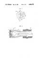
- FIG. 1is an end view of a temperature-compensated pressure sensor in accordance with the present invention
- FIG. 2is a sectional elevation view of the pressure sensor of FIG. 1, taken along the lines 2--2 of FIG. 1;
- FIG. 3is an electrical circuit that may be employed in using the pressure sensor of the present invention.
- FIG. 4is a diagramatic view of the pressure sensor connected to a calibration device and to a meter instrument that may be used in practicing the method of this invention.
- the pressure sensor 10includes an elongated, generally cylindrical, housing 12, preferably constructed of stainless steel or a like suitable material, which surrounds the axially extending portion of an internal chamber 13.
- Elongated housing 12has an opening 14 at one end thereof in which is mounted a sensor mounting ring 16 that is preferably constructed of silicon or a similar material which matches the expansion coefficient of a sensor gage element 20.
- Sensor gage element 20is mounted on ring 16 and will be described in greater detail hereinafter.
- the sensor mounting ring 16is secured in the opening 14 by an epoxy fillet 18, although other suitable affixing means could be employed.
- the other end 19 of housing 12is adapted to be fixedly connected to an elongate catheter 82 which is used to interconnect the pressure sensor 10 with an external metering and calibrating location when the sensor is at an in vivo measurement site.
- the sensor mounting ring 16has an opening 22 over which is sealed a pressure responsive element 24, for example a flexible diaphragm constructed of surgical grade silicone rubber or the like.
- a pressure responsive element 24for example a flexible diaphragm constructed of surgical grade silicone rubber or the like.
- a force transmitting membershown generally at 25, which includes a force summing plate 26 and a shaft 28 integral therewith.
- the force transmitting member 25should be bonded to one or the other of the pressure responsive element 24 and the sensor gage element 20, but not to both.
- the shaft 28 of force transmitting member 25is made sufficiently long so as to pre-stress the pressure responsive element 24 and to insure that the force transmitting member is in contact with, and providing an initial strain on, the sensor gage element 20 when both sides of the pressure responsive element 24 are exposed to a common pressure source, for example atmospheric pressure.
- a common pressure sourcefor example atmospheric pressure.
- the pressure responsive element 24 and force transmitting member 25apply about a five gram initial load on the sensor gage element 20 under such conditions of pressure.
- the amount of this initial loadis not critical so long as some initial strain is applied to the sensor gage element 20 in order to facilitate the calibration to be described hereinafter.
- the sensor gage element 20is substantially U-shaped and includes a median or bight portion 30 and leg portions or elements 32 and 34.
- the sensor gage element 20is of the piezoresistive type and is constructed such as to form a monolithic bifurcated silcon strain gage which is cut from a single site of a doped silicon crystal.
- An electrical contact 36is disposed on the sensor gage element 20 at the bight portion 30 thereof; an electrical contact 38 is disposed on the sensor gage element 20 at the end of the leg portion 32 thereof; and, an electrical contact 40 is disposed on the sensor gage element 20 at the end of the leg portion 34 thereof.
- the electrical contacts 36-40are coupled to a circuit which will be hereinafter described in conjunction with the illustration of FIG. 3.
- the sensor gage element 20is adhesively or otherwise fastened to the sensor mounting ring 16 and is positioned so that only leg portion 34 thereof is in contact with the shaft 28 of force transmitting member 25. As a result, when pressure acts upon the pressure responsive element 24, this force is imparted to the piezoresistive leg portion 34 of the sensor gage element 20.
- the other piezoresistive leg portion 32 of the sensor element 20is not exposed to any pressure except for the ambient environmental pressure within the internal chamber 13 of housing 12. Insulated electrical leads are connected to the electrical contacts 36, 38 and 40 and are joined in a cable 42 for connection to an electrical circuit, shown generally at 44 in FIGS. 3 and 4.
- the piezoresistive leg portions 32 and 34 of sensor gage element 20are connected to electrical circuit 44 in such a manner that the leg portion 32 can serve either as a biological temperature sensor of tissue in the adjacent environment, or as a temperature compensator for the pressure sensor leg portion 34.
- the electrical circuit 44comprises an essentially conventional Wheatstone bridge that includes an excitation supply 46 connected at one end thereof to a current limiting resistor 48 through an on/off switch 50, and at the other end thereof to another current limiting resistor 52. Also included in the Wheatstone bridge are fixed bridge-balancing resistor 54 and a variable bridge-balancing resistor or potentiometer 56, the latter serving to permit calibration of the Wheatstone bridge circuitry. The output signal of the Wheatstone bridge circuitry appears across a pair of conductors 57, 58.
- the junction of the fixed bridge-balancing resistor 54 and the variable bridge-balancing resistor 56is connected to the bridge output signal conductor 57.
- the other bridge output signal conductor 58is connected to the electrical contact 36 that is disposed on the bight portion 30 of sensor gage element 20.
- the current limiting resistor 48is connected at the end thereof which is remote from switch 50 to the junction of the fixed bridge-balancing resistor 54 and the electrical contact 38 disposed at the end of the piezoresistive leg portion 32 of sensor gage element 20.
- the end of the current limiting resistor 52 which is remote from the excitation supply 46is connected to a conductor 59 which interconnects the variable bridge-balancing resistor 56 and the wiper of a double throw-single pole switch 60.
- One contact 62 of the switch 60is electrically connected to the electrical contact 40 disposed on the piezoresistive leg portion 34 of sensor gage element 20.
- a fixed resistance 64is connected between the other contact 66 of switch 60 and the electrical contact 36 disposed at the bight portion 30 of the sensor gage element 20.
- a conventional Wheatstone bridgeis provided with the exception that, at any given time, one or the other of piezoresistive leg portion 34 and fixed resistor 64, but not both, may be selectively switched into the Wheatstone bridge circuit 44.
- the wiper of the switch 60When the wiper of the switch 60 is in the position illustrated in FIG. 3, contacting pole 62, the piezoresistive leg portion 34 of sensor gage element 20 is in the Wheatstone bridge circuit 44 and the output across the bridge output signal conductors 57 and 58 is indicative of the pressure imparted to the piezoresistive leg portion 34 but is compensated for changes in temperature by virtue of the inclusion of the piezoresistive leg portion 32 in the bridge circuit 44.
- the fixed resistance 64selected to be of a suitable value, is placed in the Wheatstone bridge circuit 44 and the output across the bridge output signal conductors 57 and 58 is indicative of the ambient environmental temperature of the surroundings of the housing 12, as sensed by the piezoresistive leg portion 32 of sensor gage element 20.
- an apparatuswhich will not only provide the user with signals representative of pressure readings compensated for temperature variations but which also will selectively give signals representative of readings of environmental temperature unaffected by the effects of the pressure to be measured.
- the components of electrical circuit 44which are shown outside of the broken lines of the pressure sensor, designated at 10 in FlG. 3, will be located in some location external to the biological body in which the pressure and temperature sensor 10 is placed.
- other configurationsfor example the placement of one or more of the fixed resistors 48, 52, 54 and 64 within the elongated housing 12, are also quite possible.
- an initial calibration procedurewhich involves setting the zero adjust and gain adjust values of a meter instrument, shown generally at 70, having an indicating meter 71 which displays the pressure readings of the sensor 10.
- a zero adjust control 72 of the meter instrument 70is set to provide an output display, or base line value, of zero millimeters (mm) of mercury (Hg).
- a pressure differential of 100 mm of Hgis then applied across the pressure responsive element 24, by drawing a vacuum within the chamber 13 of the sensor 10, and a gain adjust control 74 is set to provide a display of 100 mm of Hg.
- An additional differential pressuree.g., 50 mm of Hg
- the linearity of the sensor 10is not significantly affected by aging and drift factors.
- the pressure differentials used in the foregoing initial calibration proceduresare provided by a calibration device or calibrator, shown generally at 80, which is capable of providing pressurized air or vacuum at precisely measured values to a catheter 82 that is connected to sensor 10 and communicates with the chamber 13 thereof.
- the calibrator 80is preferably a Model PPS-1 Calibrator made by Thermometrics, Inc., of 808 U.S. Highway 1, Edison, N.J. 08817, the assignee of the present invention.
- Calibrator 80includes a pressure switch 84 and a vacuum switch 86 for selectively actuating the calibrator to either apply a pressure or a vacuum at an output fitting or outlet 88 thereof, to provide pressurized air or a vacuum through a conduit 90 and coupling unit 91 to the interior of catheter 82. Precision variation of the pressure or vacuum is achieved via a control knob 92 that is suitably coupled to the pressure and vacuum sources.
- a temperature-regulated heat sink or well 94is also provided on the calibrator 80. The sensor 10 may be placed into the heat sink 94 in order to check the initial calibration of the sensor at a known temperature, preferably 37 degrees centigrade, at atmospheric pressure.
- a digital temperature readout device 96, and a manometer 98 calibrated in millimeters of mercury,are employed for providing precise readings of the values of the temperature of heat sink 94 and of the pressure or vacuum at output fitting 88, respectively.
- the cable 42which interconnects sensor gage element 20 with the Wheatstone bridge circuitry 44, passes from the pressure sensor 10 through the interior of catheter 82 and through the wall of the coupling unit 91 to the circuitry 44.
- the passage of cable 42 through the wall of coupling unit 91is via wires or terminals that are hermetically sealed t the wall in order to avoid leakage of air through the unit at this point.
- the meter instrument 70is preferably one or the other of the following pressure monitors:
- the initial, in vitro, calibration procedurein accordance with the method of the invention continues as follows.
- a back pressure P R greater than atmospheric pressureis applied to internal chamber 13 via catheter 82, which is connected to the end 19 of housing 12, and a record is made of the back pressure P Ro that corresponds to the point at which separation of the force transmitting member 25, either from the piezoresistive leg element 34 (if the force transmitting member is adhered to the pressure responsive element 24) or from the pressure responsive element 24 (if the force transmitting member is adhered to the piezoresistive leg element only), occurs.
- This zero reference back pressure value P Rois defined as the value for which the initial strain on the piezoresistive leg element 34 disappears (i.e., goes to zero).
- the senor 10may be inserted into the blood stream of a biological subject and positioned at a site at which in vivo measurements are to be made of pressure and temperature.
- the calibrationcan be checked without removing the sensor from its in vivo measurement site by using the following procedure:
- step (iii)Subtract from the value of P Rc obtained in step (ii), above, the value of the zero reference back pressure P Ro obtained during the initial in vitro calibration, referred to earlier, to obtain the true differential pressure P Dt , and compare the value of P Dt so obtained with the value of P D observed in step (i) above. If the values of P Dt and P D compared in this step (iii) are in substantial agreement, the pressure sensor 10 and meter instrument 70 can be assumed to be in calibration and, thus, recalibration thereof is not required. On the other hand, if such values are not in substantial agreement, the pressure sensor 10 and meter instrument 70 can be assumed to be out of calibration, and recalibration in accordance with the following should be undertaken.
- step (v)Return the back pressure in chamber 13 to atmospheric pressure and observe the displayed in vivo pressure P D . If no significant change has occurred from the value of P D observed in step (i), above, adjust the gain control 74 to obtain a new displayed pressure P Dn given by the equation P Dn equals the displayed pressure P D obtained in this step (v) divided by the gain G obtained in step (iv) immediately above.
- step (vii)If the displayed in vivo pressure P D observed in step (v) above has changed significantly from the value of P D observed in the initial in vivo pressure check of step (i) earlier, instead of adjusting the gain control to obtain a new displayed pressure P Dn as called for in step (v) above, slowly increase the back pressure P R until the displayed value stops decreasing, record the new back pressure value P Rcn corresponding to this point, and subtract the value of P Ro , which was obtained during the initial in vitro calibration, from P Rcn to obtain a new true differential pressure P Tn (Note that the displayed pressure P D at any given time is equal to the gain factor G times the sum of the true pressure differential P T or P Tn plus the zero offset Z).
- step (viii)Adjust the gain control 74 to obtain a new displayed pressure P Dn given by the equation P Dn equals the displayed pressure P D obtained in step (v), above, divided by the gain factor G obtained in step (iv). (In effect, the gain is adjusted to make the gain factor G, as determined in step (iv), unity. This can be verified if necessary by repeating step (iv) after the gain adjustment is made).
- step (ix)Adjust the zero adjustment control 72 so that the new displayed pressure P Dn is made equal to the true differential pressure P Tn determined from step (vii), above.
- an improved pressure sensoris provided by the present invention, which pressure sensor permits calibration of its zero offset due to drift while the pressure sensor is located at an in vivo measurement site.
- the present inventionprovides improved methods for checking the calibration of a pressure sensor, and the meter and electrical circuitry associated therewith, and for recalibrating the same as necessary while the pressure sensor remains in such in vivo measurement site.
Landscapes
- Health & Medical Sciences (AREA)
- Life Sciences & Earth Sciences (AREA)
- Physics & Mathematics (AREA)
- Cardiology (AREA)
- General Physics & Mathematics (AREA)
- Heart & Thoracic Surgery (AREA)
- Molecular Biology (AREA)
- Pathology (AREA)
- Engineering & Computer Science (AREA)
- Biomedical Technology (AREA)
- Physiology (AREA)
- Medical Informatics (AREA)
- Biophysics (AREA)
- Surgery (AREA)
- Animal Behavior & Ethology (AREA)
- General Health & Medical Sciences (AREA)
- Public Health (AREA)
- Veterinary Medicine (AREA)
- Vascular Medicine (AREA)
- Measuring Fluid Pressure (AREA)
Abstract
Description
Claims (4)
Priority Applications (1)
| Application Number | Priority Date | Filing Date | Title |
|---|---|---|---|
| US07/192,604US4886070A (en) | 1988-05-11 | 1988-05-11 | Method of in vivo calibration of a pressure sensor |
Applications Claiming Priority (1)
| Application Number | Priority Date | Filing Date | Title |
|---|---|---|---|
| US07/192,604US4886070A (en) | 1988-05-11 | 1988-05-11 | Method of in vivo calibration of a pressure sensor |
Publications (1)
| Publication Number | Publication Date |
|---|---|
| US4886070Atrue US4886070A (en) | 1989-12-12 |
Family
ID=22710355
Family Applications (1)
| Application Number | Title | Priority Date | Filing Date |
|---|---|---|---|
| US07/192,604Expired - Fee RelatedUS4886070A (en) | 1988-05-11 | 1988-05-11 | Method of in vivo calibration of a pressure sensor |
Country Status (1)
| Country | Link |
|---|---|
| US (1) | US4886070A (en) |
Cited By (50)
| Publication number | Priority date | Publication date | Assignee | Title |
|---|---|---|---|---|
| US5067491A (en)* | 1989-12-08 | 1991-11-26 | Becton, Dickinson And Company | Barrier coating on blood contacting devices |
| US5133358A (en)* | 1990-09-07 | 1992-07-28 | Becton, Dickinson And Company | Apparatus for rezeroing an in vivo pressure sensor and method for rezeroing |
| US5203340A (en)* | 1990-09-07 | 1993-04-20 | Becton, Dickinson And Company | Apparatus for rezeroing an in vivo pressure sensor and method for rezeroing |
| US5247171A (en)* | 1992-04-17 | 1993-09-21 | Fiberoptic Sensor Technologies, Inc. | Drift correction for fiberoptic pressure sensors |
| US5257630A (en)* | 1992-05-15 | 1993-11-02 | Thermometrics, Inc. | Pressure sensing probe with calibration capability |
| US5383855A (en)* | 1992-08-20 | 1995-01-24 | Medex, Inc. | Electronically monitored angioplasty system |
| US5422478A (en)* | 1992-04-17 | 1995-06-06 | Fiberoptic Sensor Technologies, Inc. | Fiberoptic pressure sensor having drift correction means for insitu calibration |
| EP0719448A4 (en)* | 1993-09-14 | 1997-03-05 | Fiberoptic Sensor Tech | Fiberoptic pressure sensor having drift correcting means for in situ calibration |
| US5916180A (en)* | 1997-10-03 | 1999-06-29 | Uromed Corporation | Calibrating pressure sensors |
| US5989199A (en)* | 1996-11-27 | 1999-11-23 | Assurance Medical, Inc. | Tissue examination |
| WO2000012004A1 (en)* | 1998-08-26 | 2000-03-09 | Becton, Dickinson And Company | Cannula tip pressure sensor |
| US6063031A (en)* | 1997-10-14 | 2000-05-16 | Assurance Medical, Inc. | Diagnosis and treatment of tissue with instruments |
| USD425980S (en)* | 1997-10-20 | 2000-05-30 | Assurance Medical, Inc. | Hand-held tissue examination device |
| US6091981A (en)* | 1997-09-16 | 2000-07-18 | Assurance Medical Inc. | Clinical tissue examination |
| US6179790B1 (en) | 1997-10-20 | 2001-01-30 | Assurance Medical, Inc. | Layer of material for use with tissue examination device |
| US6221023B1 (en)* | 1995-12-01 | 2001-04-24 | Kabushiki Kaisha Tokai Rika Denki Seisakusho | Sensor for intra-corporeal medical device and a method of manufacture |
| US6546787B1 (en) | 1999-03-25 | 2003-04-15 | Regents Of The University Of Minnesota | Means and method for modeling and treating specific tissue structures |
| US20040019285A1 (en)* | 2002-05-14 | 2004-01-29 | Neal Eigler | Apparatus for minimally invasive calibration of implanted pressure transducers |
| US20040074281A1 (en)* | 2002-10-16 | 2004-04-22 | Lobdell Donn D. | Testing of pressure sensor in surgical cassette |
| WO2004035112A3 (en)* | 2002-10-16 | 2004-07-01 | Alcon Inc | Pressure sensing in surgical console |
| US20040178878A1 (en)* | 2003-03-10 | 2004-09-16 | Electrovac, Fabrikation Elektrotechnischer Spezialartikel Gesellschaft M.B.H. | Temperature sensor |
| US20040261534A1 (en)* | 2003-06-30 | 2004-12-30 | Mikhail Boukhny | Noninvasive pressure sensing assembly |
| US6993954B1 (en) | 2004-07-27 | 2006-02-07 | Tekscan, Incorporated | Sensor equilibration and calibration system and method |
| WO2005107583A3 (en)* | 2002-09-26 | 2006-12-28 | Savacor Inc | Pressure transducer system optimized for implantation in a patient |
| EP1782728A1 (en)* | 1999-11-01 | 2007-05-09 | Masimo Corporation | Apparatus and method for measuring an induced perturbation to determine a physiological parameter |
| US20080034836A1 (en)* | 2002-05-14 | 2008-02-14 | Pacesetter, Inc. | System for calibrating implanted sensors |
| CN102042897A (en)* | 2009-10-12 | 2011-05-04 | 西安威尔罗根能源科技有限公司 | Pressure checking device of pressure sensor |
| US8714021B2 (en) | 2012-02-27 | 2014-05-06 | Amphenol Thermometrics, Inc. | Catheter die and method of fabricating the same |
| US8760637B2 (en) | 2010-08-30 | 2014-06-24 | Alcon Research, Ltd. | Optical sensing system including electronically switched optical magnification |
| US8857264B2 (en) | 2012-03-30 | 2014-10-14 | Amphenol Thermometrics, Inc. | Catheter die |
| WO2014186500A3 (en)* | 2013-05-17 | 2015-01-29 | The Medical College Of Wisconsin, Inc. | Compression device for abnormal esophageal sphincter funtionality |
| US9247900B2 (en) | 2004-07-13 | 2016-02-02 | Dexcom, Inc. | Analyte sensor |
| US20160220125A1 (en)* | 2015-01-30 | 2016-08-04 | Infineon Technologies Ag | Implantable Vessel Fluid Sensor |
| US9526449B2 (en) | 2010-06-07 | 2016-12-27 | The Medical College Of Wisconsin, Inc. | Detection and treatment of abnormal esophageal sphincter functionality |
| US9808567B2 (en) | 2012-12-14 | 2017-11-07 | Gambro Lundia Ab | Diaphragm repositioning for pressure pod using position sensing |
| JP2018038792A (en)* | 2016-08-31 | 2018-03-15 | ニプロ株式会社 | Pressure measurement device |
| CN109688911A (en)* | 2016-08-31 | 2019-04-26 | 尼普洛株式会社 | Pressure measuring device, guide wire connector, guide wire and method for manufacturing guide wire |
| US10376694B2 (en) | 2008-10-09 | 2019-08-13 | Virender K. Sharma | Method and apparatus for stimulating the vascular system |
| US10524703B2 (en) | 2004-07-13 | 2020-01-07 | Dexcom, Inc. | Transcutaneous analyte sensor |
| US10603489B2 (en) | 2008-10-09 | 2020-03-31 | Virender K. Sharma | Methods and apparatuses for stimulating blood vessels in order to control, treat, and/or prevent a hemorrhage |
| US10610136B2 (en) | 2005-03-10 | 2020-04-07 | Dexcom, Inc. | System and methods for processing analyte sensor data for sensor calibration |
| EP3508115A4 (en)* | 2016-08-31 | 2020-10-14 | Nipro Corporation | PRESSURE MEASURING DEVICE, GUIDEWIRE CONNECTOR, GUIDEWIRE, AND METHOD FOR MANUFACTURING A GUIDEWIRE |
| US11141105B2 (en) | 2016-03-11 | 2021-10-12 | Respiratory Technology Corporation | Long-term therapeutic pressure applicator and real-time monitoring system |
| WO2021214489A1 (en)* | 2020-04-24 | 2021-10-28 | Clinical Technology Limited | Device for measuring a pressure differential |
| EP1565219B2 (en)† | 2002-05-31 | 2021-11-03 | KCI Licensing, Inc. | Wound treatment apparatus |
| US11221266B2 (en)* | 2019-05-22 | 2022-01-11 | Baker Hughes Oilfield Operations Llc | Automatic zero reset for a pressure transducer |
| US11630020B2 (en) | 2020-12-21 | 2023-04-18 | Industrial Technology Research Institute | Pressure sensor with calibration device and calibration method thereof |
| RU218745U1 (en)* | 2022-10-18 | 2023-06-08 | Федеральное государственное унитарное предприятие "Всероссийский научно-исследовательский институт метрологии им. Д.И. Менделеева" | Device for verification and calibration of vacuum gauges |
| CN118408677A (en)* | 2024-07-01 | 2024-07-30 | 芯康生物医学科技(杭州)有限公司 | Negative pressure calibration device |
| US12138858B2 (en)* | 2020-05-01 | 2024-11-12 | Voltera Inc. | Systems and methods for continuous flow control of printable material in additive manufacturing |
Citations (17)
| Publication number | Priority date | Publication date | Assignee | Title |
|---|---|---|---|---|
| US3088323A (en)* | 1960-02-10 | 1963-05-07 | Gulton Ind Inc | Piezoresistive transducer |
| US3550583A (en)* | 1967-05-13 | 1970-12-29 | Toyoda Chuo Kenkyusho Kk | Needle-shaped pressure transducer |
| US3703099A (en)* | 1969-11-12 | 1972-11-21 | Ici Ltd | Pressure transducer |
| US3710781A (en)* | 1970-10-12 | 1973-01-16 | T Huthcins | Catheter tip pressure transducer |
| US3724274A (en)* | 1971-02-11 | 1973-04-03 | Millar Instruments | Pressure transducers and method of physiological pressure transducers |
| US3748623A (en)* | 1972-07-25 | 1973-07-24 | Millar Instruments | Pressure transducers |
| US3831588A (en)* | 1972-10-16 | 1974-08-27 | Device Res Inc | Pressure sensing device |
| US4023562A (en)* | 1975-09-02 | 1977-05-17 | Case Western Reserve University | Miniature pressure transducer for medical use and assembly method |
| US4191193A (en)* | 1976-02-29 | 1980-03-04 | Mitsubishi Petrochemical Co. Ltd. | Catheter head-type transducer |
| US4274423A (en)* | 1977-12-15 | 1981-06-23 | Kabushiki Kaisha Toyota Chuo Kenkyusho | Catheter tip pressure transducer |
| US4342218A (en)* | 1980-01-16 | 1982-08-03 | Forrest Fox | Method and apparatus for zeroing and calibrating an invasive blood pressure monitoring system |
| US4407296A (en)* | 1980-09-12 | 1983-10-04 | Medtronic, Inc. | Integral hermetic impantable pressure transducer |
| US4554927A (en)* | 1983-08-30 | 1985-11-26 | Thermometrics Inc. | Pressure and temperature sensor |
| US4610256A (en)* | 1984-09-25 | 1986-09-09 | Utah Medical Products, Inc. | Pressure transducer |
| US4658829A (en)* | 1985-10-10 | 1987-04-21 | Utah Medical Products, Inc. | Method and apparatus for pressure transducer calibration and simulation |
| US4672974A (en)* | 1985-06-14 | 1987-06-16 | Lee Arnold St J | Method and apparatus for "zeroing" and calibrating a catheter-tip gauge-pressure transducer |
| US4760730A (en)* | 1987-07-14 | 1988-08-02 | Medex, Inc. | Calibration system for blood pressure transducer |
- 1988
- 1988-05-11USUS07/192,604patent/US4886070A/ennot_activeExpired - Fee Related
Patent Citations (18)
| Publication number | Priority date | Publication date | Assignee | Title |
|---|---|---|---|---|
| US3088323A (en)* | 1960-02-10 | 1963-05-07 | Gulton Ind Inc | Piezoresistive transducer |
| US3550583A (en)* | 1967-05-13 | 1970-12-29 | Toyoda Chuo Kenkyusho Kk | Needle-shaped pressure transducer |
| US3703099A (en)* | 1969-11-12 | 1972-11-21 | Ici Ltd | Pressure transducer |
| US3710781A (en)* | 1970-10-12 | 1973-01-16 | T Huthcins | Catheter tip pressure transducer |
| US3724274A (en)* | 1971-02-11 | 1973-04-03 | Millar Instruments | Pressure transducers and method of physiological pressure transducers |
| US3748623A (en)* | 1972-07-25 | 1973-07-24 | Millar Instruments | Pressure transducers |
| US3831588A (en)* | 1972-10-16 | 1974-08-27 | Device Res Inc | Pressure sensing device |
| US4023562A (en)* | 1975-09-02 | 1977-05-17 | Case Western Reserve University | Miniature pressure transducer for medical use and assembly method |
| US4191193A (en)* | 1976-02-29 | 1980-03-04 | Mitsubishi Petrochemical Co. Ltd. | Catheter head-type transducer |
| US4274423A (en)* | 1977-12-15 | 1981-06-23 | Kabushiki Kaisha Toyota Chuo Kenkyusho | Catheter tip pressure transducer |
| US4342218A (en)* | 1980-01-16 | 1982-08-03 | Forrest Fox | Method and apparatus for zeroing and calibrating an invasive blood pressure monitoring system |
| US4407296A (en)* | 1980-09-12 | 1983-10-04 | Medtronic, Inc. | Integral hermetic impantable pressure transducer |
| US4554927A (en)* | 1983-08-30 | 1985-11-26 | Thermometrics Inc. | Pressure and temperature sensor |
| US4610256A (en)* | 1984-09-25 | 1986-09-09 | Utah Medical Products, Inc. | Pressure transducer |
| US4610256B1 (en)* | 1984-09-25 | 1988-06-21 | ||
| US4672974A (en)* | 1985-06-14 | 1987-06-16 | Lee Arnold St J | Method and apparatus for "zeroing" and calibrating a catheter-tip gauge-pressure transducer |
| US4658829A (en)* | 1985-10-10 | 1987-04-21 | Utah Medical Products, Inc. | Method and apparatus for pressure transducer calibration and simulation |
| US4760730A (en)* | 1987-07-14 | 1988-08-02 | Medex, Inc. | Calibration system for blood pressure transducer |
Cited By (107)
| Publication number | Priority date | Publication date | Assignee | Title |
|---|---|---|---|---|
| US5067491A (en)* | 1989-12-08 | 1991-11-26 | Becton, Dickinson And Company | Barrier coating on blood contacting devices |
| US5133358A (en)* | 1990-09-07 | 1992-07-28 | Becton, Dickinson And Company | Apparatus for rezeroing an in vivo pressure sensor and method for rezeroing |
| US5203340A (en)* | 1990-09-07 | 1993-04-20 | Becton, Dickinson And Company | Apparatus for rezeroing an in vivo pressure sensor and method for rezeroing |
| US5247171A (en)* | 1992-04-17 | 1993-09-21 | Fiberoptic Sensor Technologies, Inc. | Drift correction for fiberoptic pressure sensors |
| WO1993021652A1 (en)* | 1992-04-17 | 1993-10-28 | Fiberoptic Sensor Technologies, Inc. | Drift correction for fiberoptic pressure sensors |
| US5422478A (en)* | 1992-04-17 | 1995-06-06 | Fiberoptic Sensor Technologies, Inc. | Fiberoptic pressure sensor having drift correction means for insitu calibration |
| US5257630A (en)* | 1992-05-15 | 1993-11-02 | Thermometrics, Inc. | Pressure sensing probe with calibration capability |
| US5383855A (en)* | 1992-08-20 | 1995-01-24 | Medex, Inc. | Electronically monitored angioplasty system |
| EP0719448A4 (en)* | 1993-09-14 | 1997-03-05 | Fiberoptic Sensor Tech | Fiberoptic pressure sensor having drift correcting means for in situ calibration |
| US6221023B1 (en)* | 1995-12-01 | 2001-04-24 | Kabushiki Kaisha Tokai Rika Denki Seisakusho | Sensor for intra-corporeal medical device and a method of manufacture |
| US5989199A (en)* | 1996-11-27 | 1999-11-23 | Assurance Medical, Inc. | Tissue examination |
| US6091981A (en)* | 1997-09-16 | 2000-07-18 | Assurance Medical Inc. | Clinical tissue examination |
| US5916180A (en)* | 1997-10-03 | 1999-06-29 | Uromed Corporation | Calibrating pressure sensors |
| US6063031A (en)* | 1997-10-14 | 2000-05-16 | Assurance Medical, Inc. | Diagnosis and treatment of tissue with instruments |
| USD425980S (en)* | 1997-10-20 | 2000-05-30 | Assurance Medical, Inc. | Hand-held tissue examination device |
| US6179790B1 (en) | 1997-10-20 | 2001-01-30 | Assurance Medical, Inc. | Layer of material for use with tissue examination device |
| WO2000012004A1 (en)* | 1998-08-26 | 2000-03-09 | Becton, Dickinson And Company | Cannula tip pressure sensor |
| US6162182A (en)* | 1998-08-26 | 2000-12-19 | Becton, Dickinson And Company | Pressure tip cannula |
| US6546787B1 (en) | 1999-03-25 | 2003-04-15 | Regents Of The University Of Minnesota | Means and method for modeling and treating specific tissue structures |
| EP1782728A1 (en)* | 1999-11-01 | 2007-05-09 | Masimo Corporation | Apparatus and method for measuring an induced perturbation to determine a physiological parameter |
| US7862513B2 (en) | 2002-05-14 | 2011-01-04 | Pacesetter, Inc. | Apparatus for minimally invasive calibration of implanted pressure transducers |
| US20040106874A1 (en)* | 2002-05-14 | 2004-06-03 | Neal Eigler | Method for minimally invasive calibration of implanted pressure transducers |
| WO2003098177A3 (en)* | 2002-05-14 | 2004-06-24 | Savacor Inc | Minimally invasive calibration of implanted pressure transducers |
| US7621879B2 (en) | 2002-05-14 | 2009-11-24 | Pacesetter, Inc. | System for calibrating implanted sensors |
| US20080034836A1 (en)* | 2002-05-14 | 2008-02-14 | Pacesetter, Inc. | System for calibrating implanted sensors |
| US7195594B2 (en) | 2002-05-14 | 2007-03-27 | Pacesetter, Inc. | Method for minimally invasive calibration of implanted pressure transducers |
| US20040019285A1 (en)* | 2002-05-14 | 2004-01-29 | Neal Eigler | Apparatus for minimally invasive calibration of implanted pressure transducers |
| EP1565219B2 (en)† | 2002-05-31 | 2021-11-03 | KCI Licensing, Inc. | Wound treatment apparatus |
| WO2005107583A3 (en)* | 2002-09-26 | 2006-12-28 | Savacor Inc | Pressure transducer system optimized for implantation in a patient |
| US6868720B2 (en) | 2002-10-16 | 2005-03-22 | Alcon, Inc. | Testing of pressure sensor in surgical cassette |
| US6955073B2 (en) | 2002-10-16 | 2005-10-18 | Alcon, Inc. | Pressure sensing in surgical console |
| WO2004035112A3 (en)* | 2002-10-16 | 2004-07-01 | Alcon Inc | Pressure sensing in surgical console |
| WO2004035111A3 (en)* | 2002-10-16 | 2004-06-24 | Alcon Inc | Testing of pressure sensor in surgical cassette |
| US20040074281A1 (en)* | 2002-10-16 | 2004-04-22 | Lobdell Donn D. | Testing of pressure sensor in surgical cassette |
| US7119654B2 (en)* | 2003-03-10 | 2006-10-10 | Electrovac, Fabrikation Elektrotechnischer Spezialartikel Gesellschaft M.B.H. | Temperature sensor |
| US20040178878A1 (en)* | 2003-03-10 | 2004-09-16 | Electrovac, Fabrikation Elektrotechnischer Spezialartikel Gesellschaft M.B.H. | Temperature sensor |
| US6941813B2 (en) | 2003-06-30 | 2005-09-13 | Alcon, Inc. | Noninvasive pressure sensing assembly |
| US20040261534A1 (en)* | 2003-06-30 | 2004-12-30 | Mikhail Boukhny | Noninvasive pressure sensing assembly |
| US10918315B2 (en) | 2004-07-13 | 2021-02-16 | Dexcom, Inc. | Analyte sensor |
| US10980452B2 (en) | 2004-07-13 | 2021-04-20 | Dexcom, Inc. | Analyte sensor |
| US11883164B2 (en) | 2004-07-13 | 2024-01-30 | Dexcom, Inc. | System and methods for processing analyte sensor data for sensor calibration |
| US10709363B2 (en) | 2004-07-13 | 2020-07-14 | Dexcom, Inc. | Analyte sensor |
| US11064917B2 (en) | 2004-07-13 | 2021-07-20 | Dexcom, Inc. | Analyte sensor |
| US9247900B2 (en) | 2004-07-13 | 2016-02-02 | Dexcom, Inc. | Analyte sensor |
| US11045120B2 (en) | 2004-07-13 | 2021-06-29 | Dexcom, Inc. | Analyte sensor |
| US11026605B1 (en) | 2004-07-13 | 2021-06-08 | Dexcom, Inc. | Analyte sensor |
| US9668677B2 (en) | 2004-07-13 | 2017-06-06 | Dexcom, Inc. | Analyte sensor |
| US10993642B2 (en) | 2004-07-13 | 2021-05-04 | Dexcom, Inc. | Analyte sensor |
| US10993641B2 (en) | 2004-07-13 | 2021-05-04 | Dexcom, Inc. | Analyte sensor |
| US10709362B2 (en) | 2004-07-13 | 2020-07-14 | Dexcom, Inc. | Analyte sensor |
| US10314525B2 (en) | 2004-07-13 | 2019-06-11 | Dexcom, Inc. | Analyte sensor |
| US10932700B2 (en) | 2004-07-13 | 2021-03-02 | Dexcom, Inc. | Analyte sensor |
| US10918314B2 (en) | 2004-07-13 | 2021-02-16 | Dexcom, Inc. | Analyte sensor |
| US10918313B2 (en) | 2004-07-13 | 2021-02-16 | Dexcom, Inc. | Analyte sensor |
| US10524703B2 (en) | 2004-07-13 | 2020-01-07 | Dexcom, Inc. | Transcutaneous analyte sensor |
| US10827956B2 (en) | 2004-07-13 | 2020-11-10 | Dexcom, Inc. | Analyte sensor |
| US10813576B2 (en) | 2004-07-13 | 2020-10-27 | Dexcom, Inc. | Analyte sensor |
| US10799159B2 (en) | 2004-07-13 | 2020-10-13 | Dexcom, Inc. | Analyte sensor |
| US10799158B2 (en) | 2004-07-13 | 2020-10-13 | Dexcom, Inc. | Analyte sensor |
| US10722152B2 (en) | 2004-07-13 | 2020-07-28 | Dexcom, Inc. | Analyte sensor |
| US6993954B1 (en) | 2004-07-27 | 2006-02-07 | Tekscan, Incorporated | Sensor equilibration and calibration system and method |
| US10610135B2 (en) | 2005-03-10 | 2020-04-07 | Dexcom, Inc. | System and methods for processing analyte sensor data for sensor calibration |
| US10610137B2 (en) | 2005-03-10 | 2020-04-07 | Dexcom, Inc. | System and methods for processing analyte sensor data for sensor calibration |
| US10925524B2 (en) | 2005-03-10 | 2021-02-23 | Dexcom, Inc. | System and methods for processing analyte sensor data for sensor calibration |
| US10918318B2 (en) | 2005-03-10 | 2021-02-16 | Dexcom, Inc. | System and methods for processing analyte sensor data for sensor calibration |
| US10716498B2 (en) | 2005-03-10 | 2020-07-21 | Dexcom, Inc. | System and methods for processing analyte sensor data for sensor calibration |
| US10617336B2 (en) | 2005-03-10 | 2020-04-14 | Dexcom, Inc. | System and methods for processing analyte sensor data for sensor calibration |
| US10743801B2 (en) | 2005-03-10 | 2020-08-18 | Dexcom, Inc. | System and methods for processing analyte sensor data for sensor calibration |
| US10918316B2 (en) | 2005-03-10 | 2021-02-16 | Dexcom, Inc. | System and methods for processing analyte sensor data for sensor calibration |
| US11051726B2 (en) | 2005-03-10 | 2021-07-06 | Dexcom, Inc. | System and methods for processing analyte sensor data for sensor calibration |
| US11000213B2 (en) | 2005-03-10 | 2021-05-11 | Dexcom, Inc. | System and methods for processing analyte sensor data for sensor calibration |
| US10610136B2 (en) | 2005-03-10 | 2020-04-07 | Dexcom, Inc. | System and methods for processing analyte sensor data for sensor calibration |
| US10709364B2 (en) | 2005-03-10 | 2020-07-14 | Dexcom, Inc. | System and methods for processing analyte sensor data for sensor calibration |
| US10918317B2 (en) | 2005-03-10 | 2021-02-16 | Dexcom, Inc. | System and methods for processing analyte sensor data for sensor calibration |
| US10856787B2 (en) | 2005-03-10 | 2020-12-08 | Dexcom, Inc. | System and methods for processing analyte sensor data for sensor calibration |
| US10898114B2 (en) | 2005-03-10 | 2021-01-26 | Dexcom, Inc. | System and methods for processing analyte sensor data for sensor calibration |
| US10813577B2 (en) | 2005-06-21 | 2020-10-27 | Dexcom, Inc. | Analyte sensor |
| US10603489B2 (en) | 2008-10-09 | 2020-03-31 | Virender K. Sharma | Methods and apparatuses for stimulating blood vessels in order to control, treat, and/or prevent a hemorrhage |
| US11517749B2 (en) | 2008-10-09 | 2022-12-06 | Virender K. Sharma | Methods and apparatuses for stimulating blood vessels in order to control, treat, and/or prevent a hemorrhage |
| US10376694B2 (en) | 2008-10-09 | 2019-08-13 | Virender K. Sharma | Method and apparatus for stimulating the vascular system |
| CN102042897A (en)* | 2009-10-12 | 2011-05-04 | 西安威尔罗根能源科技有限公司 | Pressure checking device of pressure sensor |
| US9526449B2 (en) | 2010-06-07 | 2016-12-27 | The Medical College Of Wisconsin, Inc. | Detection and treatment of abnormal esophageal sphincter functionality |
| US11707283B2 (en) | 2010-06-07 | 2023-07-25 | The Medical College Of Wisconsin, Inc. | Detection and treatment of abnormal upper esophageal sphincter functionality |
| US10660653B2 (en) | 2010-06-07 | 2020-05-26 | The Medical College Of Wisconsin, Inc. | Detection and treatment of abnormal upper esophageal sphincter functionality |
| US8760637B2 (en) | 2010-08-30 | 2014-06-24 | Alcon Research, Ltd. | Optical sensing system including electronically switched optical magnification |
| US8714021B2 (en) | 2012-02-27 | 2014-05-06 | Amphenol Thermometrics, Inc. | Catheter die and method of fabricating the same |
| US8857264B2 (en) | 2012-03-30 | 2014-10-14 | Amphenol Thermometrics, Inc. | Catheter die |
| US9808567B2 (en) | 2012-12-14 | 2017-11-07 | Gambro Lundia Ab | Diaphragm repositioning for pressure pod using position sensing |
| US11819186B2 (en) | 2013-05-17 | 2023-11-21 | The Medical College Of Wisconsin, Inc. | Compression device and pressure sensor for treatment of abnormal upper esophageal sphincter functionality |
| US10478196B2 (en) | 2013-05-17 | 2019-11-19 | The Medical College Of Wisconsin, Inc. | Compression device and pressure sensor for treatment of abnormal upper esophageal sphincter functionality |
| WO2014186500A3 (en)* | 2013-05-17 | 2015-01-29 | The Medical College Of Wisconsin, Inc. | Compression device for abnormal esophageal sphincter funtionality |
| US10709456B2 (en) | 2013-05-17 | 2020-07-14 | The Medical College Of Wisconsin, Inc. | Compression device and pressure sensor for treatment of abnormal upper esophageal sphincter functionality |
| US10433736B2 (en)* | 2015-01-30 | 2019-10-08 | Infineon Technologies Ag | Implantable vessel fluid sensor |
| US20160220125A1 (en)* | 2015-01-30 | 2016-08-04 | Infineon Technologies Ag | Implantable Vessel Fluid Sensor |
| US11141105B2 (en) | 2016-03-11 | 2021-10-12 | Respiratory Technology Corporation | Long-term therapeutic pressure applicator and real-time monitoring system |
| CN109688911A (en)* | 2016-08-31 | 2019-04-26 | 尼普洛株式会社 | Pressure measuring device, guide wire connector, guide wire and method for manufacturing guide wire |
| CN109688911B (en)* | 2016-08-31 | 2022-03-29 | 尼普洛株式会社 | Pressure measuring device |
| EP3903675A1 (en)* | 2016-08-31 | 2021-11-03 | Nipro Corporation | Pressure measurement device |
| US11707200B2 (en) | 2016-08-31 | 2023-07-25 | Nipro Corporation | Pressure measurement device, guide wire connector, guide wire, and method for manufacturing guide wire |
| JP2018038792A (en)* | 2016-08-31 | 2018-03-15 | ニプロ株式会社 | Pressure measurement device |
| EP3508115A4 (en)* | 2016-08-31 | 2020-10-14 | Nipro Corporation | PRESSURE MEASURING DEVICE, GUIDEWIRE CONNECTOR, GUIDEWIRE, AND METHOD FOR MANUFACTURING A GUIDEWIRE |
| US11221266B2 (en)* | 2019-05-22 | 2022-01-11 | Baker Hughes Oilfield Operations Llc | Automatic zero reset for a pressure transducer |
| WO2021214489A1 (en)* | 2020-04-24 | 2021-10-28 | Clinical Technology Limited | Device for measuring a pressure differential |
| US12138858B2 (en)* | 2020-05-01 | 2024-11-12 | Voltera Inc. | Systems and methods for continuous flow control of printable material in additive manufacturing |
| US11630020B2 (en) | 2020-12-21 | 2023-04-18 | Industrial Technology Research Institute | Pressure sensor with calibration device and calibration method thereof |
| RU218745U1 (en)* | 2022-10-18 | 2023-06-08 | Федеральное государственное унитарное предприятие "Всероссийский научно-исследовательский институт метрологии им. Д.И. Менделеева" | Device for verification and calibration of vacuum gauges |
| CN118408677A (en)* | 2024-07-01 | 2024-07-30 | 芯康生物医学科技(杭州)有限公司 | Negative pressure calibration device |
Similar Documents
| Publication | Publication Date | Title |
|---|---|---|
| US4886070A (en) | Method of in vivo calibration of a pressure sensor | |
| US4554927A (en) | Pressure and temperature sensor | |
| US4672974A (en) | Method and apparatus for "zeroing" and calibrating a catheter-tip gauge-pressure transducer | |
| US3831588A (en) | Pressure sensing device | |
| US5257630A (en) | Pressure sensing probe with calibration capability | |
| US8216151B2 (en) | Pressure wire assembly | |
| US4274423A (en) | Catheter tip pressure transducer | |
| JP2832461B2 (en) | Pressure meter catheter | |
| EP0888744B1 (en) | In vivo zeroing of catheter pressure sensor | |
| US5158087A (en) | Differential temperature measurement for ultrasound transducer thermal control | |
| JP2898751B2 (en) | Transmitter that shares overpressure protection and expands measurement capability | |
| JP3532573B2 (en) | Pressure transmitter with remote seal diaphragm | |
| US4436438A (en) | Multiple probe temperature measuring system and probes therefor | |
| US5460049A (en) | Digitally-temperature-compensated strain-gauge pressure measuring apparatus | |
| JPH01501503A (en) | Pressure transducer with integrated digital temperature compensation means | |
| AU2014203450B2 (en) | Pressure wire assembly | |
| US20180010974A1 (en) | Pressure sensor system | |
| US3847017A (en) | Strain measuring system | |
| US4576035A (en) | Self-calibrating differential condition sensor | |
| EP0803054B1 (en) | A temperature compensation method in pressure sensors | |
| JP2001517993A (en) | Pressure measuring device | |
| US5691478A (en) | Device and method for remote zeroing of a biological fluid pressure measurement device | |
| RU2108556C1 (en) | Method and device for capacitive temperature compensation and double-plate capacitive pressure converter for its realization | |
| US6056697A (en) | Pressure catheter calibration chamber | |
| RU2097721C1 (en) | Pressure converter |
Legal Events
| Date | Code | Title | Description |
|---|---|---|---|
| AS | Assignment | Owner name:THERMOMETRICS, INC., 808 U.S. HIGHWAY 1, EDISON, N Free format text:ASSIGNMENT OF ASSIGNORS INTEREST.;ASSIGNOR:DEMAREST, PHILIP, C.;REEL/FRAME:004892/0715 Effective date:19880506 Owner name:THERMOMETRICS, INC., NEW JERSEY Free format text:ASSIGNMENT OF ASSIGNORS INTEREST;ASSIGNOR:DEMAREST, PHILIP, C.;REEL/FRAME:004892/0715 Effective date:19880506 | |
| CC | Certificate of correction | ||
| FEPP | Fee payment procedure | Free format text:PAT HLDR NO LONGER CLAIMS SMALL ENT STAT AS SMALL BUSINESS (ORIGINAL EVENT CODE: LSM2); ENTITY STATUS OF PATENT OWNER: LARGE ENTITY Free format text:PAYOR NUMBER ASSIGNED (ORIGINAL EVENT CODE: ASPN); ENTITY STATUS OF PATENT OWNER: LARGE ENTITY | |
| FPAY | Fee payment | Year of fee payment:4 | |
| FPAY | Fee payment | Year of fee payment:8 | |
| REMI | Maintenance fee reminder mailed | ||
| LAPS | Lapse for failure to pay maintenance fees | ||
| STCH | Information on status: patent discontinuation | Free format text:PATENT EXPIRED DUE TO NONPAYMENT OF MAINTENANCE FEES UNDER 37 CFR 1.362 | |
| FP | Lapsed due to failure to pay maintenance fee | Effective date:20011212 |